WO2017187890A1 - 電動工具 - Google Patents
電動工具 Download PDFInfo
- Publication number
- WO2017187890A1 WO2017187890A1 PCT/JP2017/013668 JP2017013668W WO2017187890A1 WO 2017187890 A1 WO2017187890 A1 WO 2017187890A1 JP 2017013668 W JP2017013668 W JP 2017013668W WO 2017187890 A1 WO2017187890 A1 WO 2017187890A1
- Authority
- WO
- WIPO (PCT)
- Prior art keywords
- capacitor
- motor
- voltage
- fan
- brushless motor
- Prior art date
- Legal status (The legal status is an assumption and is not a legal conclusion. Google has not performed a legal analysis and makes no representation as to the accuracy of the status listed.)
- Ceased
Links
Images







Classifications
-
- H—ELECTRICITY
- H02—GENERATION; CONVERSION OR DISTRIBUTION OF ELECTRIC POWER
- H02P—CONTROL OR REGULATION OF ELECTRIC MOTORS, ELECTRIC GENERATORS OR DYNAMO-ELECTRIC CONVERTERS; CONTROLLING TRANSFORMERS, REACTORS OR CHOKE COILS
- H02P6/00—Arrangements for controlling synchronous motors or other dynamo-electric motors using electronic commutation dependent on the rotor position; Electronic commutators therefor
- H02P6/28—Arrangements for controlling current
-
- B—PERFORMING OPERATIONS; TRANSPORTING
- B25—HAND TOOLS; PORTABLE POWER-DRIVEN TOOLS; MANIPULATORS
- B25F—COMBINATION OR MULTI-PURPOSE TOOLS NOT OTHERWISE PROVIDED FOR; DETAILS OR COMPONENTS OF PORTABLE POWER-DRIVEN TOOLS NOT PARTICULARLY RELATED TO THE OPERATIONS PERFORMED AND NOT OTHERWISE PROVIDED FOR
- B25F5/00—Details or components of portable power-driven tools not particularly related to the operations performed and not otherwise provided for
-
- B—PERFORMING OPERATIONS; TRANSPORTING
- B25—HAND TOOLS; PORTABLE POWER-DRIVEN TOOLS; MANIPULATORS
- B25F—COMBINATION OR MULTI-PURPOSE TOOLS NOT OTHERWISE PROVIDED FOR; DETAILS OR COMPONENTS OF PORTABLE POWER-DRIVEN TOOLS NOT PARTICULARLY RELATED TO THE OPERATIONS PERFORMED AND NOT OTHERWISE PROVIDED FOR
- B25F5/00—Details or components of portable power-driven tools not particularly related to the operations performed and not otherwise provided for
- B25F5/008—Cooling means
-
- H—ELECTRICITY
- H02—GENERATION; CONVERSION OR DISTRIBUTION OF ELECTRIC POWER
- H02K—DYNAMO-ELECTRIC MACHINES
- H02K11/00—Structural association of dynamo-electric machines with electric components or with devices for shielding, monitoring or protection
- H02K11/0094—Structural association with other electrical or electronic devices
-
- H—ELECTRICITY
- H02—GENERATION; CONVERSION OR DISTRIBUTION OF ELECTRIC POWER
- H02K—DYNAMO-ELECTRIC MACHINES
- H02K11/00—Structural association of dynamo-electric machines with electric components or with devices for shielding, monitoring or protection
- H02K11/04—Structural association of dynamo-electric machines with electric components or with devices for shielding, monitoring or protection for rectification
- H02K11/049—Rectifiers associated with stationary parts, e.g. stator cores
- H02K11/05—Rectifiers associated with casings, enclosures or brackets
-
- H—ELECTRICITY
- H02—GENERATION; CONVERSION OR DISTRIBUTION OF ELECTRIC POWER
- H02K—DYNAMO-ELECTRIC MACHINES
- H02K11/00—Structural association of dynamo-electric machines with electric components or with devices for shielding, monitoring or protection
- H02K11/30—Structural association with control circuits or drive circuits
- H02K11/33—Drive circuits, e.g. power electronics
-
- H—ELECTRICITY
- H02—GENERATION; CONVERSION OR DISTRIBUTION OF ELECTRIC POWER
- H02K—DYNAMO-ELECTRIC MACHINES
- H02K5/00—Casings; Enclosures; Supports
- H02K5/04—Casings or enclosures characterised by the shape, form or construction thereof
- H02K5/20—Casings or enclosures characterised by the shape, form or construction thereof with channels or ducts for flow of cooling medium
- H02K5/207—Casings or enclosures characterised by the shape, form or construction thereof with channels or ducts for flow of cooling medium with openings in the casing specially adapted for ambient air
-
- H—ELECTRICITY
- H02—GENERATION; CONVERSION OR DISTRIBUTION OF ELECTRIC POWER
- H02K—DYNAMO-ELECTRIC MACHINES
- H02K7/00—Arrangements for handling mechanical energy structurally associated with dynamo-electric machines, e.g. structural association with mechanical driving motors or auxiliary dynamo-electric machines
- H02K7/14—Structural association with mechanical loads, e.g. with hand-held machine tools or fans
-
- H—ELECTRICITY
- H02—GENERATION; CONVERSION OR DISTRIBUTION OF ELECTRIC POWER
- H02K—DYNAMO-ELECTRIC MACHINES
- H02K9/00—Arrangements for cooling or ventilating
- H02K9/02—Arrangements for cooling or ventilating by ambient air flowing through the machine
- H02K9/04—Arrangements for cooling or ventilating by ambient air flowing through the machine having means for generating a flow of cooling medium
-
- H—ELECTRICITY
- H02—GENERATION; CONVERSION OR DISTRIBUTION OF ELECTRIC POWER
- H02P—CONTROL OR REGULATION OF ELECTRIC MOTORS, ELECTRIC GENERATORS OR DYNAMO-ELECTRIC CONVERTERS; CONTROLLING TRANSFORMERS, REACTORS OR CHOKE COILS
- H02P23/00—Arrangements or methods for the control of AC motors characterised by a control method other than vector control
- H02P23/0086—Arrangements or methods for the control of AC motors characterised by a control method other than vector control specially adapted for high speeds, e.g. above nominal speed
- H02P23/009—Arrangements or methods for the control of AC motors characterised by a control method other than vector control specially adapted for high speeds, e.g. above nominal speed using field weakening
-
- H—ELECTRICITY
- H02—GENERATION; CONVERSION OR DISTRIBUTION OF ELECTRIC POWER
- H02P—CONTROL OR REGULATION OF ELECTRIC MOTORS, ELECTRIC GENERATORS OR DYNAMO-ELECTRIC CONVERTERS; CONTROLLING TRANSFORMERS, REACTORS OR CHOKE COILS
- H02P6/00—Arrangements for controlling synchronous motors or other dynamo-electric motors using electronic commutation dependent on the rotor position; Electronic commutators therefor
- H02P6/06—Arrangements for speed regulation of a single motor wherein the motor speed is measured and compared with a given physical value so as to adjust the motor speed
-
- B—PERFORMING OPERATIONS; TRANSPORTING
- B23—MACHINE TOOLS; METAL-WORKING NOT OTHERWISE PROVIDED FOR
- B23D—PLANING; SLOTTING; SHEARING; BROACHING; SAWING; FILING; SCRAPING; LIKE OPERATIONS FOR WORKING METAL BY REMOVING MATERIAL, NOT OTHERWISE PROVIDED FOR
- B23D45/00—Sawing machines or sawing devices with circular saw blades or with friction saw discs
- B23D45/16—Hand-held sawing devices with circular saw blades
-
- B—PERFORMING OPERATIONS; TRANSPORTING
- B23—MACHINE TOOLS; METAL-WORKING NOT OTHERWISE PROVIDED FOR
- B23D—PLANING; SLOTTING; SHEARING; BROACHING; SAWING; FILING; SCRAPING; LIKE OPERATIONS FOR WORKING METAL BY REMOVING MATERIAL, NOT OTHERWISE PROVIDED FOR
- B23D47/00—Sawing machines or sawing devices working with circular saw blades, characterised only by constructional features of particular parts
- B23D47/12—Sawing machines or sawing devices working with circular saw blades, characterised only by constructional features of particular parts of drives for circular saw blades
-
- B—PERFORMING OPERATIONS; TRANSPORTING
- B23—MACHINE TOOLS; METAL-WORKING NOT OTHERWISE PROVIDED FOR
- B23D—PLANING; SLOTTING; SHEARING; BROACHING; SAWING; FILING; SCRAPING; LIKE OPERATIONS FOR WORKING METAL BY REMOVING MATERIAL, NOT OTHERWISE PROVIDED FOR
- B23D59/00—Accessories specially designed for sawing machines or sawing devices
- B23D59/001—Measuring or control devices, e.g. for automatic control of work feed pressure on band saw blade
Definitions
- the present invention relates to an electric tool using a motor as a drive source.
- the electrostatic capacity of the capacitor provided in the power tool is small, and the voltage cannot be sufficiently smoothed.
- the voltage output from the rectifying and smoothing circuit is lower than the induced voltage generated by the motor, and there is a non-energization period in which voltage cannot be applied from the power supply side to the motor (no current flows from the power supply side to the motor).
- the rotational speed cannot be made constant as the load on the motor increases.
- the electric tool is an electric circular saw
- the rotational speed of the saw blade is not constant.
- an object of the present invention is to provide an electric tool that does not cause a non-energization period of a drive voltage applied to a motor.
- the present invention provides a brushless motor that rotates when an applied voltage is equal to or higher than an induced voltage, a supply circuit that applies a drive voltage to the brushless motor, and a control unit that controls the supply circuit.
- the supply circuit rectifies and outputs an alternating voltage, a capacitor that smoothes the voltage input through the rectifier circuit, and performs a switching operation based on a PWM signal,
- a switching circuit capable of adjusting a period during which the drive voltage is applied, and the control unit sets a duty ratio within a predetermined range and outputs the PWM signal having the set duty ratio to the switching circuit.
- the switching operation can be controlled, and the control unit changes the duty ratio and rotates the brushless motor at a target rotational speed. It is possible to perform constant rotation speed control to control the capacitor, and the capacitor has a capacity such that the smoothed voltage is always equal to or higher than the induced voltage when the constant rotation speed control is being performed.
- a featured electric tool is provided.
- the control unit can control the supply circuit to stop the application of the drive voltage from the supply circuit to the brushless motor.
- the capacitor preferably has a capacity such that the driving voltage is always equal to or higher than the induced voltage when the current flowing through the brushless motor is equal to or lower than the maximum allowable current value.
- the capacitance of the capacitor is preferably 500 microfarads or more.
- the capacitor preferably includes a plurality of capacitors connected in parallel. With such a configuration, the size of each capacitor can be reduced.
- the brushless motor has a rotor rotatable around a rotation shaft, and further includes a fan that rotates coaxially with the rotation shaft, the brushless motor, the supply circuit, and a housing that houses the fan.
- the housing has an opening, and an air path extending from the fan to the opening is formed inside the housing, the capacitor is disposed on the air path, and the longitudinal direction of the capacitor is, It is preferable to extend from the upstream to the downstream in the flowing direction of the flowing cooling air.
- the capacitor can be efficiently cooled by the cooling air along the longitudinal direction.
- the apparatus further includes a board on which the capacitor and the switching circuit are mounted, and a board case that houses the board, and the capacitor is disposed at an end of the board case on the opening side.
- the switching circuit is preferably disposed in contact with the substrate case. According to such a configuration, heat generated by the switching circuit is conducted to the board case and radiated from the board case.
- a filler is filled between the capacitor and the control board. According to such a configuration, the position of the capacitor can be reliably fixed with respect to the control board.
- the brushless motor includes a rotor that is rotatable about a rotation shaft, and includes a fan that rotates coaxially with the rotation shaft, a substrate on which the switching circuit is mounted, the brushless motor, the supply circuit, and the fan.
- a housing for housing the housing the housing having a first opening and a second opening that are opened at different positions, a first air passage extending from the fan to the first opening, and the fan And a second air path from the first air path to the second opening, wherein the substrate is disposed on the first air path, and the capacitor is preferably disposed on the second air path.
- the substrate can be cooled by the cooling air passing through the first air passage, and the capacitor can be cooled by the cooling air passing through the second air passage.
- the brushless motor includes a rotor that is rotatable about a rotation shaft, a centrifugal fan that rotates coaxially with the rotation shaft, one surface on which the capacitor is disposed, and the other surface on which the switching circuit is disposed. It is preferable that the substrate further includes a substrate extending in the radial direction of the rotating shaft.
- the cooling air passes through one surface and the other surface of the substrate, and the capacitor and the switching circuit can be effectively cooled.
- the brushless motor includes a rotor that can rotate about a rotation shaft, and further includes a centrifugal fan that rotates coaxially with the rotation shaft, and a substrate on which the capacitor is mounted, and the capacitor is disposed on the substrate with respect to the substrate. It is preferable to arrange on the centrifugal fan side.
- the condenser can directly receive the cooling air from the centrifugal fan, the cooling efficiency of the condenser can be improved.
- the speed of the brushless motor is stabilized at the target speed, so that when the power tool cuts the workpiece, the cut surface of the cut surface of the workpiece is cut. Can be prevented from becoming non-uniform.
- FIG. 1 is a block diagram showing an electrical configuration of an electric circular saw according to a first embodiment of the present invention.
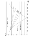
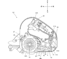
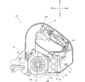
- FIG 12 is a graph showing the minimum value of the drive voltage, which summarizes the experimental results of FIGS. It is a side view which shows the inside of the electric circular saw which concerns on the 2nd Embodiment of this invention. It is a side view which shows the inside of the electric circular saw which concerns on the 3rd Embodiment of this invention. It is a side view which shows the inside of the electric circular saw which concerns on the 4th Embodiment of this invention.
- An electric circular saw 1 that is an electric tool shown in FIG. 1 includes a housing 2 that rotatably supports a saw blade 8 and a base 3, and the saw blade 8 is slid by sliding the base 3 on a workpiece. It is a tool which cuts a work material by rotation of.
- the front shown in the figure is defined as the front direction
- the rear is defined as the rear direction
- the upper direction is defined as the upper direction
- the lower direction is defined as the lower direction
- the right when viewed from the rear direction is defined as the right direction.
- the left is defined as the left direction (the front side of FIG. 1 is the right direction and the back of the page is the left direction).
- the housing 2 is provided so as to be tiltable left and right with respect to the base 3.
- the base 3 is a plate-shaped member made of metal such as aluminum.
- a hole (not shown) that penetrates in the vertical direction and extends in the front-rear direction is formed in the base 3, and the hole (not shown) allows the saw blade 8 to enter.
- the longitudinal direction (front-rear direction) of the base 3 coincides with the cutting direction.
- the housing 2 includes a main body housing 21, a handle portion 22, a saw cover 23, and a motor housing 24 (FIG. 2). As shown in FIG. 2, the saw cover 23 is provided on the right side of the main body housing 21, and the motor housing 24 protrudes to the left side from the main body housing 21.
- the main body housing 21 is made of resin, for example, and supports the saw blade 8 so as to be rotatable.
- the motor housing 24 accommodates the motor 4 and the control board 6.
- the saw blade 8 has a disk shape and is rotatably provided on the right side of the main body housing 21, and is rotationally driven by the rotation of the motor 4.
- the handle portion 22 is a portion that is gripped when the user uses the electric circular saw 1, and extends in the front-rear direction above the motor housing 24.
- the handle portion 22 is provided with a trigger 22 ⁇ / b> A for controlling the driving of the motor 4.
- the trigger 22A is electrically connected to the control board 6 inside the housing 2, and outputs a start signal for starting the motor 4 to the control board 6 when the user pushes the trigger 22A upward.
- the saw cover 23 is made of, for example, metal and has an arc shape in a side view along the outer edge of the saw blade 8.
- the saw cover 23 is provided on the right side of the main body housing 21 and is substantially half on the upper side of the saw blade 8. Covering.
- the saw cover 23 includes a protective cover 23A.
- the protective cover 23 ⁇ / b> A is made of, for example, resin, and is provided to be rotatable along the outer edge of the saw blade 8. In a state in which the cutting operation is not performed, the protective cover 23A covers the lower half of the peripheral end (portion protruding downward from the base 3) excluding a part of the front of the saw blade 8.
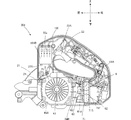
- FIG. 2 is a plan view of the electric circular saw 1, in which a part of the main body housing 21 and a part of the motor housing 24 are omitted, and the internal structure of the housing 2 is shown.
- the motor housing 24 is made of, for example, resin, and includes a motor housing chamber 21b that houses the motor 4, a control board housing chamber 21c that houses the control board 6, and a housing chamber 21a that houses the fan 43A. ing. More specifically, the motor housing 24 includes a bottom wall 24B (FIG. 3), and a left wall 24L in which an intake port 31a and an exhaust port 31b are formed. An inner wall 27 and a partition wall 28 are provided inside the motor housing 24.
- the inner wall 27 extends in the front-rear direction on the right side of the saw blade 8 and extends to the left side at the rear end portion thereof and is connected to the left wall 24L.
- the partition wall 28 is provided between the intake port 31a and the exhaust port 31b in the front-rear direction.
- the partition wall 28 is connected to the left wall 24L and extends rightward from the left wall 24L to a predetermined position on the left side of the inner wall 27. That is, the partition wall 28 is disposed with a space in the left-right direction from the inner wall 27.
- the motor housing 24, the inner wall 27, and the partition wall 28 define each storage chamber (a storage chamber 21 a, a motor storage chamber 21 b, and a control board storage chamber 21 c) in the main body housing.
- the control board 6 is an example of a supply circuit.
- the motor 4 and the fan 43 ⁇ / b> A are disposed in front of the partition wall 28, and the substrate case 71 is disposed behind the partition wall 28.
- the substrate case 71 accommodates the control substrate 6 and is disposed in the control substrate accommodating chamber 21c.
- the motor housing 24, the inner wall 27, and the partition wall 28 form an air path P1 from the intake port 31a to the exhaust port 31b.
- the intake port 31a is provided to communicate with the motor housing chamber 21b and the outside, and the exhaust port 31b is provided to communicate with the control board housing chamber 21c and the outside.
- the fan 43A is a centrifugal fan. As the fan 43A rotates, cooling air flows from the intake port 31a toward the exhaust port 31b.
- the air path P1 is substantially U-shaped, extends rightward from the air inlet 31a to the fan 43A, and extends rearward from the fan 43A to the board case 71 (control board 6). From 71 (control board 6) to the exhaust port 31b, it extends in the left direction.
- the motor 4, the fan 43A, and the board case 71 (control board 6) are arranged in this order from upstream to downstream in the direction in which the cooling air flows.
- the intake port 31a and the exhaust port 31b coincide with the vertical height of the fan 43A. That is, the intake port 31a and the exhaust port 31b have a region overlapping the fan 43A in the vertical direction.
- the air path P1 is an example of an air path or a first air path.
- the substrate case 71 is made of a material having high thermal conductivity such as metal. As shown in FIGS. 4 (A) and 4 (B), the substrate case 71 is formed in a box shape with the upper part opened, and is provided on the fixed wall 71F (FIG. 3) and the outer periphery of the fixed wall 71F. Side wall 71S. As shown in FIG. 3, the substrate case 71 accommodates the control substrate 6 therein.
- the board case 71 is fixed to the bottom wall 24 ⁇ / b> B of the motor housing 24 (control board housing chamber 21 c) via a rib 72 inside the motor housing 24.
- the fixed wall 71 ⁇ / b> F is disposed at a distance from the bottom wall 24 ⁇ / b> B of the motor housing 24. Accordingly, the cooling air can pass between the substrate case 71 and the motor housing 24, and the cooling air can be efficiently cooled by adopting a configuration in which the cooling air passes above and below the substrate case 71.
- the electric circular saw 1 includes a power cord 30 that can be connected to a commercial AC power source of 100 V and 50 Hz as an example.
- the power cord 30 extends rearward from the rear left side of the motor housing 24.
- the power cord 30 is configured to be connectable to a commercial AC power source 500.
- the power cord 30 is electrically connected to the control board 6, and the power of the commercial AC power source 500 is supplied to the motor 4 via the power cord 30 and the control board 6.
- the motor 4 is a three-phase brushless DC motor including a stator 41 and a rotor 42.
- the stator 41 includes three-phase coils U, V, and W that are star-connected.
- the coils U, V, and W are each connected to the control board 6.
- the rotor 42 includes two sets of permanent magnets each having a north pole and a south pole.
- a Hall element 42A is arranged at a position facing the permanent magnet.
- the hall element 42 ⁇ / b> A outputs a position signal of the rotor 42 to the control board 6.
- the rotation shaft 43 shown in FIG. 2 is connected to the rotation center of the rotor 42 and rotates integrally with the rotor 42.
- the rotating shaft 43 extends in the left-right direction and is rotatably supported by the motor housing 24.
- the rotation shaft 43 is connected to the rotation center of the fan 43A. Therefore, the fan 43 ⁇ / b> A can rotate coaxially with the motor 4.
- the fan 43A rotates and cooling air is generated.
- the cooling air passes through the vicinity of the motor 4 and the control board 6 to cool the motor 4 and the control board 6.
- the fan 43A is a centrifugal fan.
- the rotating shaft 43 is connected to the saw blade 8 via a speed reduction mechanism (not shown). The saw blade 8 is rotated by the rotational drive of the rotary shaft 43.
- the control board 6 includes a rectifying / smoothing unit 61, a switching unit 62, a current detection resistor 91, and a control unit 64.
- the rectifying / smoothing unit 61 includes a diode bridge 61A and two smoothing capacitors 61B (hereinafter simply referred to as a capacitor 61B) connected in parallel, and is connected to the commercial AC power supply 500 and the switching unit 62, respectively.
- the diode bridge 61A and the switching unit 62 are examples of a rectifier circuit and a switching circuit, respectively.
- the capacitor 61B is an electrolytic capacitor.
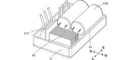
- the diode bridge 61 ⁇ / b> A and the two capacitors 61 ⁇ / b> B are mounted on the front surface (upper side) of the control board 6, and the switching unit 62 is mounted on the back surface (lower side) of the control board 6. ing.
- a filler 81 is filled between the capacitor 61 ⁇ / b> B and the control board 6.
- the capacitor 61 ⁇ / b> B is positioned with respect to the control board 6 and the board case 71 by the filler 81.
- the diode bridge 61A has a rectangular heat sink at the front, and heat generated by the diode bridge 61A is dissipated by the heat sink.
- the switching unit 62 is disposed below the heat sink 63 and is in contact with the heat sink 63 and the fixed wall 71F. Thereby, the heat generated in the switching unit 62 is conducted to the heat sink 63 and the substrate case 71. As described above, since the cooling air can pass between the substrate case 71 and the motor housing 24, the substrate case 71 is efficiently cooled by the cooling air.
- the control unit 64 is provided between the heat sink 63 and the control board 6 in contact with the heat sink 63, for example. According to such a configuration, heat generated by the control unit 64 is also radiated by the heat sink 63.
- Each capacitor 61 ⁇ / b> B has a substantially cylindrical shape in which the bus bar is in the longitudinal direction. As shown in FIG. 2, the capacitor 61B is arranged such that its longitudinal direction extends in the left-right direction. In other words, the capacitor 61B extends in the longitudinal direction from the upstream to the downstream in the direction in which the cooling air flows. The capacitor 61B is provided adjacent to the end of the control board 6 in the direction in which the cooling air flows, and is efficiently cooled by the cooling air along the longitudinal direction.
- the diode bridge 61 ⁇ / b> A performs full-wave rectification on the AC voltage input from the commercial AC power supply 500.
- the capacitor 61B smoothes the full-wave rectified voltage and outputs it to the switching unit 62.
- the two capacitors 61B are connected in parallel between the input line and the output line of the commercial AC power supply 500.
- the number of capacitors 61B is not limited to two. If the total capacitance of capacitors 61B connected in parallel is equal to or greater than a predetermined capacitance (for example, 1050 microfarads) described later, three or more capacitors 61B may be used. Good. Alternatively, if the capacitance of the single capacitor 61B is equal to or greater than the predetermined capacitance, only one capacitor 61B may be used. However, when a plurality of capacitors 61B are provided, the size of one capacitor can be made smaller than when a single capacitor 61B is provided. Thereby, each capacitor
- the switching unit 62 is a switching circuit in which six FETs Q1 to Q6 are incorporated.
- the six FETs Q1 to Q6 are connected in a three-phase bridge format.
- the gates of the six FETs Q1 to Q6 are connected to the control unit 64, and the drains or sources of the six FETs Q1 to Q6 are connected to the coils U, V, and W that are star-connected.
- the six FETs Q1 to Q6 perform a switching operation that repeatedly turns on and off according to the drive signal input from the control unit 64, and the coils U, V, Supply to W.
- FETs Q1 to Q6 correspond to switching circuits.
- As the switching unit 62 six insulated gate bipolar transistors may be used instead of the FETs Q1 to Q6.
- the switching unit 62 applies a drive voltage to the motor 4.
- the current detection resistor 91 is a resistor for detecting a current flowing through the motor 4, and is connected between the rectifying / smoothing unit 61 and the switching unit 62.
- the control unit 64 includes a current detection circuit 64A, a rotor position detection circuit 64B, a drive signal output unit 64D, and a calculation unit 64E.
- the current detection circuit 64A takes in the voltage drop value of the current detection resistor 91 and outputs it to the calculation unit 64E.
- the rotor position detection circuit 64B outputs the position signal of the rotor 42 input from the hall element 42A of the motor 4 to the calculation unit 64E.
- the drive signal output unit 64D is connected to each gate of the six FETs Q1 to Q6, and applies a voltage to each gate of the six FETs Q1 to Q6 based on the drive signal input from the calculation unit 64E.
- the FET with the voltage applied to the gate is turned on to allow energization to the motor 4, and the FET with no voltage applied to the gate is turned off to interrupt the energization to the motor 4. To do.
- the calculation unit 64E includes a central processing unit (CPU) (not shown) for outputting a driving signal based on the processing program and data, a ROM (not shown) for storing the processing program, control data, various threshold values, and the like. And a RAM (not shown) for temporarily storing data.
- the calculation unit 64E generates a control signal for alternately switching the predetermined FETs Q1 to Q6 based on the position signal of the rotor 42 input from the rotor position detection circuit 64B, and outputs the control signal as a drive signal.
- a predetermined coil among the coils U, V, and W is alternately energized to rotate the rotor 42 in a predetermined rotation direction.
- the drive signal output to the FETs Q4 to Q6 connected to the negative power supply side is output as a pulse width modulation signal (PWM signal).
- PWM signal pulse width modulation signal
- the control unit 64 sets the duty ratio, outputs a PWM signal with the set duty ratio to the FETs Q4 to Q6, and turns the FETs Q4 to Q6 on and off at high speed.
- the control unit 64 adjusts the amount of power supplied to the motor 4 (more specifically, the period during which the drive voltage is applied to the motor 4), and the motor The rotational speed (rotational speed) of 4 is controlled.
- the PWM signal is a signal that can change the period during which the FET is turned on in the switching period (predetermined time), that is, the signal output time (pulse width).
- the duty ratio is a ratio of the signal output time in the switching cycle (predetermined time).
- the control unit 64 changes the amount of power supplied to the motor 4 by changing the duty ratio and changing the ON time in the switching period of the FETs Q4 to Q6. In other words, the control unit 64 adjusts the period during which the drive voltage is applied to the motor 4 by changing the duty ratio.
- the calculation unit 64E controls the start / stop of the motor 4 based on the start signal from the trigger 22A.
- the electric power supplied to the motor 4 is determined based on the result of comparing the rotational speed of the motor 4 calculated from the position signal of the rotor 42 inputted from the rotor position detection circuit 64B with the target rotational speed.
- the rotation speed is adjusted so as to become the target rotation speed.
- the number of rotations of the saw blade 8 decelerated by the decelerating mechanism is adjusted to 4100 rpm.
- the control unit 64 can execute constant rotation speed control in which the rotation speed of the motor 4 becomes the target rotation speed.
- calculation unit 64E changes the duty ratio within a predetermined range.
- the predetermined range is 10% to 100%.
- the predetermined range is not limited to this, and may be 5% to 90%, for example.
- the calculation unit 64E performs control to output the PWM signal having the duty ratio set by the drive signal output unit 64D to the corresponding FETs Q4 to Q6, and controls the motor 4 to rotate at the target rotation number. Execute. When a load exceeding a predetermined value is applied to the saw blade 8, even if the duty ratio is set to the upper limit value (100% in the present embodiment), the motor 4 cannot be maintained at the target rotational speed, and the rotational speed decreases. .
- the computing unit 64E executes an operation that keeps the duty ratio fixed at the upper limit value. Note that when the load applied to the saw blade 8 increases, the induced voltage of the motor 4 decreases, so that the current flowing through the motor 4 increases. In the present embodiment, constant rotational speed control is performed until the effective current flowing through the motor 4 is 6A. If the current flowing through the motor 4 exceeds 6 A as the load applied to the saw blade 8 increases, the rotational speed of the motor 4 decreases while maintaining the maximum value of the duty ratio in a predetermined range.
- the calculation unit 64E monitors the amount of current flowing through the motor 4 based on the detection result of the current detection circuit 64A. When the current flowing through the motor 4 exceeds the overcurrent threshold (18A in the present embodiment), the calculation unit 64E turns off the FETs Q4 to Q6 and stops the switching unit 62 from applying the drive voltage to the motor 4. .
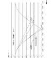
- FIG. 6A shows a driving voltage applied to the motor 4 of the present application when the load applied to the saw blade 8 (or the load applied to the motor 4, hereinafter the same) is constant and constant rotation speed control is performed. It is the graph which showed V1.
- the horizontal axis indicates time, and the vertical axis indicates voltage.
- a virtual drive voltage V2 (hereinafter referred to as virtual voltage V2) when the capacitor 61B is not provided in the rectifying and smoothing unit 61 is indicated by a dotted line, and induction of the motor 4 when the motor 4 is rotating at the target rotational speed.
- the voltage V3 is indicated by a one-dot chain line.
- the virtual voltage V2 is substantially equal to the voltage obtained by full-wave rectification of the AC voltage, and the voltage value becomes 0 at a predetermined cycle. If the virtual voltage V2 is applied to the motor 4 while the motor 4 is rotating at the target rotational speed, the virtual voltage V2 becomes equal to or lower than the induced voltage V3 in the period T1, and a current flows to the motor 4. Absent. For this reason, the rotation of the motor 4 cannot be maintained at the target rotation speed, and the rotation of the saw blade 8 cannot be maintained constant. In this state, when the workpiece is cut, the cut surface of the cut surface becomes uneven. In the following description, a period in which the drive voltage is lower than the induced voltage and no current flows to the motor 4 as in the period T1 of the virtual voltage V2 is referred to as a non-energization period.
- FIG. 6B shows the drive voltage Vc1 of the electric circular saw of the comparative example in which a smoothing capacitor having a small capacity is mounted.
- the period T2 is a non-energization period in which the drive voltage V1 is less than the induced voltage V3.
- the non-energization period T2 is shorter than the non-energization period T1, it still exists.
- the total capacity of the capacitor 61B is set to a sufficiently large amount. Therefore, as shown in FIG. 6A, the drive voltage V1 is always equal to or higher than the induced voltage V3, and the non-energization period does not exist in the drive voltage V1. That is, the electric circular saw 1 of the present embodiment includes a capacitor 61B having a total capacity such that the drive voltage V1 is always equal to or higher than the induced voltage V3. In other words, the total capacity is set to a predetermined capacity such that the drive voltage V1 is always greater than or equal to the induced voltage V3. In the present embodiment, the predetermined capacity is set to a value of 1050 microfarads or more.
- FIG. 6A illustrates the case where the load applied to the saw blade 8 is constant (and the case where constant rotation speed control is performed).
- FIG. 7 shows the torque (vertical axis) generated by the motor with respect to the effective current (A) (horizontal axis) flowing through the motor 4, the rotational speed (vertical axis) of the motor 4, and the induced voltage (vertical axis) generated by the motor 4. Axis).
- the graph of FIG. 7 explains the torque generated by the motor, the rotational speed of the motor, and the induced voltage generated by the motor.
- the torque in FIG. 7 increases as the load applied to the saw blade 8 (or the load applied to the motor 4) increases.
- the constant rotational speed control is performed with an effective current flowing through the motor 4 of 6 A or less.
- the control unit increases the duty ratio. Thereby, the electric current which flows into the motor 4 increases.
- the torque increases.
- the induced voltage generated by the motor 4 is substantially constant.
- the amount of current flowing through the motor 4 changes according to the load applied to the saw blade 8 (torque generated by the motor 4).
- the rotational speed of the motor 4 gradually decreases. That is, constant rotation speed control is not performed in this range. That is, in this range, the duty ratio is set to the maximum value (100% in the present embodiment), but since the load applied to the saw blade 8 is increased, the rotational speed of the motor 4 is decreased. When the rotational speed decreases in this way, the induced voltage also decreases. When the induced voltage decreases, the current flowing through the motor 4 increases. Thus, when the rotational speed of the motor 4 decreases in a range where the constant rotational speed control cannot be maintained (a range where the current is larger than 6A in FIG. 7), the amount of current flowing through the motor 4 increases.
- the capacitor 61B of the present embodiment is determined so as to satisfy the following two conditions.
- the first condition is to have a total capacity such that the drive voltage is always greater than or equal to the induced voltage generated by the motor 4 when the constant rotational speed control is being executed.
- the second condition is that, in a range where constant rotation speed control cannot be maintained, the capacitor 61B is configured such that when the current flowing through the motor 4 is equal to or lower than the overcurrent threshold (maximum allowable current value), the drive voltage is always equal to or higher than the induced voltage. To have a total capacity.
- the total capacity is determined based on the following experiment.
- a plurality of electric circular saws are prepared.
- Each electric circular saw has the same configuration as the electric circular saw 1 described above, and the total capacity of the capacitors is different from each other.
- the total capacities of the capacitors mounted on the five electric circular saws are 400, 500, 600, 1050, and 1400 microfarads, respectively.
- Loads are applied to the saw blades of these five electric circular saws, and the drive voltage at each load is measured. 8 to 11 show the measured drive voltages, and show the results when the current flowing through the motor is 4A, 6A, 12A, and 18A, respectively.
- the load applied to the saw blade 8 increases in the order of 4A, 6A, 12A, and 18A.
- the vertical axis represents voltage (V), and the horizontal axis represents time (s).
- 8 to 11 also show the voltage when the commercial AC power supply 500 is full-wave rectified and the induced voltage generated in the motor 4.
- FIG. 8 shows a driving voltage in the constant rotation speed control when the current flowing through the motor is 4A.
- the total capacity is 300 microfarads or more, there is no non-energization period. Accordingly, the drive voltages of the five electric circular saws are always higher than the induced voltage. In other words, regardless of the total capacity of 400, 500, 600, 1050, 1400 microfarads, the drive voltage is always greater than the induced voltage of the motor.
- FIG. 9 shows the drive voltage in the constant rotation speed control when the current flowing through the motor is 6A.
- 6A is the maximum value of the current flowing through the motor in the constant rotational speed control, and is the amount of current when the load applied to the saw blade is the maximum in the range of the constant rotational speed control.
- the total capacity is 500 microfarads or more
- the drive voltage is always more than the induced voltage. Accordingly, when the total capacity is 400 microfarads, there is a non-energization period, but when the total capacity is 500, 600, 1050, and 1400 microfarads, the drive voltage is always higher than the induced voltage of the motor.
- FIG. 10 shows the drive voltage when the current flowing through the motor is 12A.
- the duty ratio is set to the maximum value (100 percent), but the motor cannot maintain the target rotational speed and rotates below the target rotational speed. .
- the induced voltage is lower than during constant speed control. In this case, when the total capacity is 400, 500, and 600 microfarads, there is a non-energization period. However, if the total capacity is 1050 and 1400 microfarads, the drive voltage is always higher than the induced voltage of the motor.
- FIG. 11 shows the drive voltage when the current flowing through the motor is 18 A, which matches the overcurrent threshold.
- the duty ratio is set to the maximum value (100%), but the motor rotates at a rotational speed lower than the target rotational speed and lower than the rotational speed in FIG.
- the induced voltage further decreases and the current flowing through the motor increases.
- the total capacity is 1050 microfarads or more
- the drive voltage is always more than the induced voltage. Therefore, when the total capacity is 600 microfarads or less, there is a non-energization period, but when the total capacity is 1050 or 1400 microfarads, the drive voltage is always higher than the induced voltage of the motor.
- the driving voltage of the electric circular saw having a total capacity of 400 and 500 microfarads is not described.
- FIG. 12 is a graph summarizing the above experimental results.
- the five curves indicated by solid lines relate to the drive voltages for the above five electric circular saws, respectively.
- the five curves shown by the solid lines in FIG. 12 show the minimum driving voltage (driving voltage minimum value) in the results of the experiments in FIGS. 8 to 11 for each total capacity, that is, the voltage after discharge. Yes.
- the minimum driving voltage when the amount of current is 4 A is about 70 V, and when the time is about 0.007 seconds in the 400 microfarad capacitor in FIG.
- the voltage value is shown.
- FIG. 12 the minimum driving voltage when the amount of current is 4 A is about 70 V, and when the time is about 0.007 seconds in the 400 microfarad capacitor in FIG. The voltage value is shown.
- the total capacity is determined such that the drive voltage is always equal to or greater than the drive voltage generated by the motor at the maximum current (6A) in the constant rotation speed control, the drive voltage when the constant rotation speed control is being executed.
- the total capacity is always higher than the induced voltage generated in the motor.
- the constant rotational speed control is not performed in the section where the current amount is 6 A or more.
- any drive voltage curve decreases as the amount of current increases.
- the required total capacity of the capacitor 61B increases as the load applied to the saw blade 8 increases (that is, the torque increases or the amount of current flowing through the motor). Therefore, when the current flowing through the motor is equal to or less than the overcurrent threshold (maximum allowable current value), the current flowing through the motor is determined to be the overcurrent threshold (maximum The result of the allowable current value) may be used.
- the total capacity is determined such that the drive voltage is always greater than or equal to the induced voltage, the total capacity is less than the overcurrent threshold (maximum allowable current value)
- the total capacity is such that the drive voltage is always greater than or equal to the induced voltage. That is, 1050 microfarads are determined as a total capacity such that the drive voltage is always equal to or higher than the induced voltage when the current flowing through the motor is equal to or lower than the overcurrent threshold (maximum allowable current value).
- the total capacity of the capacitor 61B mounted on the electric circular saw 1 is 1050 microfarads in the present embodiment, but it may be more than that.
- the capacitor 61B has a total capacity such that the drive voltage is always equal to or higher than the induced voltage generated by the motor 4 when the constant rotation speed control is being executed. Yes.
- the constant rotation speed control when the drive voltage becomes less than the induced voltage, the rotation speed of the motor 4 cannot be made constant, and the rotation speed of the motor 4 becomes unstable.
- the cut surface of the cut surface of the workpiece becomes uneven.
- the electric circular saw 1 of the present embodiment since the drive voltage is always equal to or higher than the induced voltage, the rotational speed of the motor 4 is stable, and therefore it is possible to prevent the cut surface from becoming uneven. Can do.
- the capacitor 61B has a capacity such that the drive voltage is always equal to or higher than the induced voltage when the current flowing through the motor 4 is equal to or less than the maximum allowable current value. . For this reason, even if the load concerning the saw blade 8 increases, the rotation speed of the motor 4 becomes unstable. Therefore, it can suppress that the cut surface of a cut surface becomes non-uniform
- 1050 microfarads is determined as the lower limit value of the total capacity that satisfies the first condition and the second condition. Accordingly, the total capacity of the capacitor 61B can be set to an arbitrary capacity of 1050 microfarads or more, but if the total capacity becomes too large, the size of the capacitor 61B increases. The larger the size of the capacitor 61B, the more difficult it is to store the capacitor 61B in the electric circular saw 1. In the present embodiment, the total capacity of the capacitor 61B is excessively increased by specifying the lower limit value of the total capacity necessary as described above and determining the total capacity to be the lower limit value or a value near the lower limit value. This can be suppressed. Therefore, it is possible to prevent the size of the capacitor 61B from being increased unnecessarily.
- the capacitor 61B Since the capacity of the capacitor 61B in the present embodiment is large, it is necessary to sufficiently cool the capacitor 61B.
- the capacitor 61B extends in the longitudinal direction from the upstream to the downstream in the direction in which the cooling air flows. For this reason, the capacitor
- the electric circular saw 101 of the second embodiment is the same as the electric circular saw 1 of the first embodiment except for the arrangement of the substrate case 71. Therefore, only the arrangement of the substrate case 71 will be described.
- the motor housing 24 has an inclined wall 24 ⁇ / b> T that extends in an upwardly inclined manner.
- the inclined wall 24T is provided on the upper side of the bottom wall 24B.
- the substrate case 71 is fixed to the upper side of the inclined wall 24T via the rib 72 so that the fixed wall 71F is along the inclined wall 24T.
- the fixed wall 71 ⁇ / b> F of the substrate case 71 is parallel to the control substrate 6. Therefore, the control board 6 is also disposed along the inclined wall 24T.
- the fan 43A is a centrifugal fan.
- the fan 43 ⁇ / b> A can rotate coaxially with the rotation shaft 43 of the motor 4.
- the control board 6 extends in the radial direction around the rotation shaft 43.
- the control board 6 is arranged in a radial direction around the rotation shaft 43 and substantially parallel to the radial direction of the position where the control board 6 is provided.
- the control board 6 and the rotating shaft 43 are arranged on a substantially straight line.
- the control substrate 6 and the bottom surface of the substrate case 71 are parallel.
- the substrate case 71 is also arranged in the radial direction around the rotation shaft 43 and substantially parallel to the radial direction of the position where the substrate case 71 is provided.
- the substrate case 71 and the rotating shaft 43 are arranged on a substantially straight line.
- the capacitor 61B is arranged such that its longitudinal direction extends in the left-right direction. In other words, the capacitor 61B extends in the longitudinal direction from the upstream to the downstream in the direction in which the cooling air flows.
- the capacitor 61B is provided adjacent to the end of the control board 6 in the direction in which the cooling air flows.
- the electric circular saw 101 is arranged in a radial direction about the rotation shaft 43 and substantially parallel to the radial direction of the position where the control board 6 is provided. .
- the capacitor 61 ⁇ / b> B is provided on the opposite side of the switching unit 62 with respect to the control board 6. That is, the capacitor 61 ⁇ / b> B is disposed on the upper side of the control board 6, and the switching unit 62 is disposed on the lower side of the control board 6.
- Both the capacitor 61B and the switching unit 62 are elements that generate heat. As described above, since the cooling air can smoothly pass through the upper side and the lower side of the control board 6, the capacitor 61B and the switching unit 62 can be efficiently cooled.
- the electric circular saw 201 of the third embodiment is the same as the electric circular saw 1 of the first embodiment except for the arrangement of the substrate case 71. Therefore, only the arrangement of the substrate case 71 will be described, and the description of other configurations will be omitted.
- the fixed wall 71F of the substrate case 71 extends in the vertical direction so that the capacitor 61B faces the fan 43A.
- the capacitor 61B is provided on the fan 43A side with respect to the fixed wall 71F and the control board 6. Further, the side wall 71S is fixed in contact with the bottom wall 24B. Therefore, the rib 72 is not provided in the third embodiment.
- the capacitor 61B is arranged such that its longitudinal direction extends in the left-right direction. In other words, the capacitor 61B extends in the longitudinal direction from the upstream to the downstream in the direction in which the cooling air flows.
- the capacitor 61B is provided adjacent to the end of the control board 6 in the direction in which the cooling air flows.
- the cooling air generated by the fan 43A can effectively pass around the condenser 61B and cool the condenser 61B.
- the side wall 71S may be fixed to the bottom wall 24B via the rib 72.
- the electric circular saw 301 of the fourth embodiment is different from the first example in that a capacitor 161B is provided instead of the capacitor 61B and the configuration of the substrate case 71 is different.
- the other configuration is the same as that of the electric circular saw 1 of the first embodiment. Therefore, only the configuration of the capacitor 161B and the substrate case 71 will be described, and the description of other configurations will be omitted.
- the capacity of the capacitor 161B is an electrolytic capacitor having the same capacity as the total capacity of the two capacitors 61B of the first embodiment.
- the capacitor 161 ⁇ / b> B is not mounted on the control board 6 and is provided inside the handle portion 22. Specifically, a plurality of bosses 22B are provided inside the handle portion 22, and the bottom surface of the cylindrical capacitor 161B is supported from below by the bosses 22B. The inside of the handle portion 22 communicates with the storage chamber 21a.
- the capacitor 161B is provided on the upper part of the centrifugal fan 43A. As shown in FIG.
- the handle portion 22 has a right end wall 22R, and an exhaust port 22a is formed in the right end wall 22R. Accordingly, an air path P2 extending from the fan 43A to the exhaust port 22a is formed in the motor housing 24 and the handle portion 22. The cooling air generated by the fan 43A passes near the condenser 161B and is discharged from the exhaust port 22a.
- the air path P2 is an example of a second air path.
- Capacitor 161 ⁇ / b> B has a substantially cylindrical shape in which the bus line is in the longitudinal direction. Capacitor 161B is arranged such that its longitudinal direction extends in the vertical direction. In other words, the capacitor 161B extends in the longitudinal direction from the upstream to the downstream in the direction in which the cooling air flows.
- the electrical configuration of the capacitor 161B is the front stage of the diode bridge 61A and is connected to the rear stage of the switching unit 62 via the cable 160 (FIG. 15), similarly to the configuration shown in FIG.
- the fixed wall 71F of the substrate case 71 extends in the vertical direction.
- the side wall 71S is fixed to the bottom wall 24B via a rib 72.
- the switching unit 62 and the diode bridge 61 ⁇ / b> A are provided on the side opposite to the substrate case 71 with respect to the control substrate 6, and face the rotating shaft 43. Therefore, the switching unit 62 is not in contact with the control board 6.
- control board 6 is not provided with the capacitor 161B. Therefore, elements such as the switching unit 62 are mounted on the control board 6 by a method different from that of the first embodiment. Specifically, the switching unit 62 is disposed on the fan 43A side with respect to the control board 6 and is disposed so as to be exposed to the cooling air.
- the capacitor 161B is provided on the top of the fan 43A.
- the cooling air generated by the fan 43A passes through the vicinity of the capacitor 161B and is discharged to the exhaust port 22a. Since the cooling air flows from the fan 43A to the vicinity of the capacitor 161B in a straight line, the capacitor 161B can be efficiently cooled. Furthermore, it can be arranged so that heat generated from the elements of the control board 6 does not affect the capacitor 161B.
- the switching unit 62 is opposed to the rotation axis of the fan 43A. For this reason, the cooling air generated by the fan 43A efficiently passes through the vicinity of the switching unit 62, and the switching unit 62 can be efficiently cooled.
- the electric power tool may not be an electric circular saw but may be another electric tool such as an electric drill.
- the switching unit 62 of the first embodiment performs an operation of switching the drive voltage applied to the coils U, V, and W and an operation of adjusting a period for applying the drive voltage based on the duty ratio. Instead, the switching unit 62 performs only the operation of switching the drive voltage applied to the coils U, V, and W, and the switching element provided separately from the switching unit 62 is used to adjust the period during which the drive voltage is applied. You may make it perform the operation
- the electric circular saw 1 may have a switch that allows an operator to select a target rotational speed.
- the drive voltage is always equal to or higher than the induced voltage when the maximum target rotational speed among selectable target rotational speeds is set as a reference and the current value is less than or equal to the maximum current value allowed to flow through the motor 4. It is sufficient that the capacitor 61B has a total capacity such that
Landscapes
- Engineering & Computer Science (AREA)
- Power Engineering (AREA)
- Mechanical Engineering (AREA)
- Microelectronics & Electronic Packaging (AREA)
- Sawing (AREA)
- Control Of Motors That Do Not Use Commutators (AREA)
Abstract
印加電圧が誘起電圧以上の時に回転駆動するブラシレスモータと、前記ブラシレスモータに電圧を印加する供給回路と、前記供給回路を制御する制御部と、を備え、前記供給回路は、交流電圧を整流して出力する整流回路と、前記整流回路を経て入力される電圧を平滑するコンデンサと、スイッチング動作を行うことで、前記駆動電圧を印加する期間を調整可能なスイッチング回路と、を備え、前記制御部は、所定の範囲内のデューティ比を設定し、設定した前記デューティ比のPWM信号を前記スイッチング回路に出力して、前記スイッチング動作を制御可能であり、前記制御部は、前記デューティ比を変更して前記ブラシレスモータを目標回転数で回転させるように制御する定回転数制御を実行可能であり、前記コンデンサは、前記定回転数制御が実行されているとき、平滑した電圧が常に誘起電圧以上になるような容量を有している電動工具を提供する。
Description
本発明は、モータを駆動源とする電動工具に関する。
従来、整流平滑回路にて交流電圧を整流平滑し、整流平滑した電圧をモータに印加することでモータを駆動する電動工具が知られている(特許文献1)。かかる整流平滑回路には整流した電圧を平滑するコンデンサが設けられている。
しかしながら、上記の電動工具に設けられたコンデンサの静電容量は小さく、電圧を十分に平滑することができなかった。そのため、整流平滑回路から出力される電圧が、モータで発生した誘起電圧より低くなり、電源側からモータへ電圧を印加することができない(電源側からモータへ電流が流れない)無通電期間が存在していた。無通電期間では、モータへの負荷が増加すると回転速度を一定にすることができなくなる。例えば、電動工具が電動丸鋸であった場合には、鋸刃の回転速度が一定しなくなる。このように回転数が安定しない鋸刃で被加工材を切断すると、切断された被加工材の切れ肌が不均一となる問題があった。
そこで本発明は、モータへの印加される駆動電圧の無通電期間を生じない電動工具を提供することを目的とする。
上記目的を達成するために、本発明は、印加される電圧が誘起電圧以上の時に回転駆動するブラシレスモータと、前記ブラシレスモータに駆動電圧を印加する供給回路と、前記供給回路を制御する制御部と、を備え、前記供給回路は、交流電圧を整流して出力する整流回路と、前記整流回路を経て入力される電圧を平滑するコンデンサと、PWM信号に基づいてスイッチング動作を行うことで、前記駆動電圧を印加する期間を調整可能なスイッチング回路と、を備え、前記制御部は、所定の範囲内のデューティ比を設定し、設定した前記デューティ比の前記PWM信号を前記スイッチング回路に出力して、前記スイッチング動作を制御可能であり、前記制御部は、前記デューティ比を変更して前記ブラシレスモータを目標回転数で回転させるように制御する定回転数制御を実行可能であり、前記コンデンサは、前記定回転数制御が実行されているとき、平滑した電圧がが常に誘起電圧以上になるような容量を有していることを特徴とする電動工具を提供している。
このような構成により、定回転数制御において、ブラシレスモータの回転数は目標回転数で安定するため、電動工具が被加工材を切断したときに、被加工材の切断面の切れ肌が不均一となることを抑制することができる。
前記ブラシレスモータに流れる電流が最大許容電流値を上回った場合には、前記制御部は、前記供給回路を制御して、前記供給回路から前記ブラシレスモータへの前記駆動電圧の印加を停止可能であって、前記コンデンサは、前記ブラシレスモータに流れる電流が前記最大許容電流値以下のとき、前記駆動電圧が常に前記誘起電圧以上になるような容量を有していることが好ましい。このような構成により、ブラシレスモータに流れる電流を制限して破損等を防ぐとと共に、最大許容電流値以下であれば常に安定して回転することができる。つまり、ブラシレスモータが回転するあらゆる状況において、被加工材の切断面の切れ肌が不均一となることを抑制することができる。
前記コンデンサの容量は500マイクロファラッド以上であることが好ましい。
前記コンデンサは、並列に接続された複数のコンデンサを有することが好ましい。このような構成により、各コンデンサのサイズを小さくすることができる。
前記ブラシレスモータは回転軸を中心に回転可能なロータを有し、前記回転軸と同軸に回転するファンと、前記ブラシレスモータと、前記供給回路と、前記ファンとを収容するハウジングと、をさらに備え、前記ハウジングは、開口部を有し、前記ハウジング内部に前記ファンから前記開口部に至る風路が形成され、前記コンデンサは、風路上に配置され、前記コンデンサの長手方向は 、前記風路を流れる冷却風の流れる方向の上流から下流に向けて延出していることが好ましい。
このような構成によれば、コンデンサの長手方向は、冷却風の上流から下流に向けて延出しているため、長手方向に沿った冷却風によりコンデンサを効率よく冷却することができる。
前記コンデンサと、前記スイッチング回路とを搭載した基板と、前記基板を収容する基板ケースと、をさらに備え、前記コンデンサは、前記基板ケースの前記開口部側端部に配置されている ことが好ましい。
前記スイッチング回路は、前記基板ケースに接触して配置されていることが好ましい。このような構成によれば、スイッチング回路で発した熱は基板ケースに伝導し、基板ケースから放熱する。
前記コンデンサと前記制御基板との間に充填剤が充填されていることが好ましい。このような構成によれば、制御基板に対して確実にコンデンサの位置を固定することができる。
記ブラシレスモータは回転軸を中心に回転可能なロータを備え、前記回転軸と同軸に回転するファンと、前記スイッチング回路を搭載した基板と、前記ブラシレスモータと、前記供給回路と、前記ファンとを収容するハウジングと、をさらに備え、前記ハウジングは、互いに異なる位置に開口した第1開口部と第2開口部とを有し、前記ファンから第1開口部に至る第1風路と、前記ファンから第2開口部に至る第2風路と、をさらに備え、前記基板は、前記第1風路上に配置されており、前記コンデンサは、前記第2風路上に配置されていることが好ましい。
このような構成によれば、第1風路を通過する冷却風によって、前記基板を冷却し、第2風路を通過する冷却風によってコンデンサを冷却することができる。
前記ブラシレスモータは回転軸を中心に回転可能なロータを備え、前記回転軸と同軸に回転する遠心ファンと、前記コンデンサが配置された一方の面と、前記スイッチング回路が配置された他方の面とを有する基板と、をさらに備え、前記基板は、前記回転軸の径方向に延出して配置されることが好ましい。
このような構成によれば、基板の一方の面と他方の面とに冷却風が通過することになり、コンデンサとスイッチング回路とを効果的に冷却することができる。
前記ブラシレスモータは回転軸を中心に回転可能なロータを備え、前記回転軸と同軸に回転する遠心ファンと、前記コンデンサを搭載した基板と、をさらに備え、前記コンデンサは、前記基板に対して前記遠心ファン側に配置されていることが好ましい。
このような構成によれば、コンデンサは遠心ファンからの冷却風を直接受けることができるため、コンデンサの冷却効率を向上させることができる。
本発明の電動工具によれば、定回転数制御において、ブラシレスモータの回転数は目標回転数で安定するため、電動工具が被加工材を切断したときに、被加工材の切断面の切れ肌が不均一となることを抑制することができる。
<第1の実施の形態> 本発明の第1の実施の形態による電動工具について図1乃至図11に基づき説明する。図1に示される電動工具である電動丸鋸1は、鋸刃8を回転可能に支持するハウジング2と、ベース3とを備えており、ベース3を被加工材に摺動させて鋸刃8の回転により被加工材を切断する工具である。説明の便宜のため、図1において、図中に示す前を前方向、後を後方向、上を上方向、下を下方向と定義し、後方向から見て右を右方向と定義し、左を左方向と定義する(図1の紙面手前が右方向、紙面奥が左方向)。
図1に示すように、ハウジング2は、ベース3に対して左右に傾動可能に設けられている。ベース3は、例えばアルミ等の金属製の板形状の部材である。ベース3には上下方向に貫通し前後方向に延びる図示せぬ孔が形成されており、図示せぬ孔は鋸刃8の進入を許容している。ベース3の長手方向(前後方向)は切断方向と一致する。
ハウジング2は、本体ハウジング21と、ハンドル部22と、ソーカバー23と、モータハウジング24(図2)とを備えている。図2に示すように、ソーカバー23は、本体ハウジング21の右側に設けられ、モータハウジング24は、本体ハウジング21より左側に突出している。本体ハウジング21は、例えば樹脂製であり、鋸刃8を回転可能に支持している。モータハウジング24はモータ4と、制御基板6とを収容している。
図1に示すように鋸刃8は、円板形状をなし、本体ハウジング21の右側において回転可能に設けられており、モータ4の回転により回転駆動される。
図1、3に示すように、ハンドル部22は、ユーザが電動丸鋸1を使用する際に把持する部分であり、モータハウジング24の上方において前後方向に延びている。またハンドル部22には、モータ4の駆動を制御するためのトリガ22Aが設けられている。トリガ22Aは、ハウジング2内部において制御基板6と電気的に接続されており、ユーザがトリガ22Aを上方に押し込むことによってモータ4を始動させる始動信号を制御基板6に出力する。
図1に示すように、ソーカバー23は、例えば金属製であり、鋸刃8の外縁に沿う側面視円弧形状をなしており、本体ハウジング21の右側に設けられて鋸刃8の上側の略半分を覆っている。またソーカバー23は、保護カバー23Aを備えている。保護カバー23Aは、例えば樹脂製であり、鋸刃8の外縁に沿って回動可能に設けられている。切断作業を行っていない状態では、保護カバー23Aは鋸刃8の前方の一部を除いた周端の下側半分(ベース3から下方に突出する部分)を覆っている。
図2は、電動丸鋸1の平面図であり、本体ハウジング21の一部と、モータハウジング24の一部とを省略し、ハウジング2の内部構造を示している。モータハウジング24は、例えば樹脂製であり、内部にはモータ4を収容するモータ収容室21bと、制御基板6を収容する制御基板収容室21cと、ファン43Aを収容する収容室21aが画成されている。より詳細には、モータハウジング24は、底壁24B(図3)と、吸気口31aと排気口31bとが形成された左壁24Lと、備えている。モータハウジング24の内部には、内壁27と、仕切壁28とが設けられている。内壁27は、鋸刃8の右側において前後方向に延び、その後端部において左側に延びて左壁24Lと接続している。仕切壁28は、前後方向において、吸気口31aと、排気口31bとの間に設けられている。仕切壁28は、左壁24Lに接続され、左壁24Lから内壁27の左側の所定の位置まで右方向に延出している。つまり、仕切壁28は内壁27から左右方向に間隔を設けて配置されている。モータハウジング24と、内壁27と、仕切壁28とによって、本体ハウジングに各収容室(収容室21a、モータ収容室21b、制御基板収容室21c)が画成されている。制御基板6は供給回路の一例である。
モータ4と、ファン43Aとは、仕切壁28の前方に配置され、基板ケース71は、仕切壁28の後方に配置されている。基板ケース71は制御基板6を収容しており、制御基板収容室21cに配置されている。図2の矢印で示されるように、モータハウジング24と、内壁27と仕切壁28とによって、吸気口31aから排気口31bに至る風路P1が形成されている。吸気口31aはモータ収容室21bと外部とを連通するように設けられ、排気口31bは制御基板収容室21cと外部とを連通するように設けられる。ここで、ファン43Aは遠心ファンである。ファン43Aが回転することにより、冷却風が吸気口31aから排気口31bに向かって流れる。具体的には、風路P1は、略コ字形状であり、吸気口31aからファン43Aまでは右方向に延び、ファン43Aから基板ケース71(制御基板6)までは後方向に延び、基板ケース71(制御基板6)から排気口31bまでは左方向に延びている。言い換えれば、風路P1上には、冷却風の流れる方向の上流から下流に向かって、モータ4、ファン43A、基板ケース71(制御基板6)が、この順序で配置されている。吸気口31aと排気口31bとは、ファン43Aの上下方向の高さと一致する。即ち、吸気口31aと排気口31bとは、ファン43Aと上下方向に関して重なる領域を有している。風路P1は、風路または第1風路の一例である。
基板ケース71は、金属などの熱伝導率の高い物質で構成されている。図4(A)、4(B)に示すように、基板ケース71は、上方が解放された箱状に形成されており、固定壁71F(図3)と、固定壁71Fの外周に設けられた側壁71Sとを備えている。図3に示すように、基板ケース71は、内部に制御基板6を収容している。基板ケース71は、モータハウジング24の内側において、リブ72を介して当該モータハウジング24(制御基板収容室21c)の底壁24Bに固定されている。即ち、固定壁71Fは、モータハウジング24の底壁24Bと間隔を隔てて配置されている。これにより、冷却風が基板ケース71とモータハウジング24との間を通過することができ、基板ケース71の上下を冷却風が通る構成とすることで効率よく冷却することができる。
図2に示すように、電動丸鋸1は、一例として100V、50Hzの商用交流電源に接続可能な電源コード30を備えている。電源コード30は、モータハウジング24の後部左側から後方に延出している。電源コード30は、商用交流電源500に接続可能に構成されている。電源コード30は、制御基板6に電気的に接続されており、商用交流電源500の電力は電源コード30及び制御基板6を介してモータ4に供給される。
図5に示すようにモータ4は、ステータ41と、ロータ42とを備える3相ブラシレスDCモータである。ステータ41はスター結線された3相のコイルU、V、Wを備えている。コイルU、V、Wはそれぞれ制御基板6に接続されている。ロータ42はN極、S極を1組とした永久磁石を2組備えている。永久磁石に対向する位置にはホール素子42Aが配置されている。ホール素子42Aは、ロータ42の位置信号を制御基板6に出力している。
図2に示す回転軸43は、ロータ42の回転中心に接続されており、ロータ42と一体に回転する。回転軸43は、左右方向に延びており、モータハウジング24に回転可能に支持されている。また、回転軸43は、ファン43Aの回転中心と接続されている。従って、ファン43Aは、モータ4と同軸に回転可能である。回転軸43が回転駆動されることで、ファン43Aが回転して、冷却風が発生する。冷却風が、モータ4及び制御基板6の近傍を通過することにより、モータ4及び制御基板6を冷却する。上述のようにファン43Aは遠心ファンである。回転軸43は図示せぬ減速機構を介して鋸刃8に接続されている。鋸刃8は、回転軸43の回転駆動によって回転する。
図5に示すように制御基板6は、整流平滑部61と、スイッチング部62と、電流検出抵抗91と、制御部64とを備えている。整流平滑部61は、ダイオードブリッジ61Aと、並列接続された2つの平滑コンデンサ61B(以下、単にコンデンサ61Bと示す)とを備え、商用交流電源500及びスイッチング部62のそれぞれに接続されている。ダイオードブリッジ61A、スイッチング部62は、それぞれ、整流回路、スイッチング回路の一例である。なお、コンデンサ61Bは電解コンデンサである。
図3に示すように、ダイオードブリッジ61Aと、2つのコンデンサ61Bとは、制御基板6の表の面(上側)に搭載され、スイッチング部62は、制御基板6の裏面(下側)に搭載されている。図4(A)、4(B)に示すように、コンデンサ61Bと制御基板6との間に充填剤81が充填されている。コンデンサ61Bは、充填剤81により制御基板6および基板ケース71に対して位置決めされている。ダイオードブリッジ61Aは、前部に長方形のヒートシンクを有しており、ダイオードブリッジ61Aで発生した熱はヒートシンクによって放熱される。スイッチング部62は、ヒートシンク63の下方に配置され、ヒートシンク63と固定壁71Fに接触している。これにより、スイッチング部62で発生した熱がヒートシンク63と基板ケース71に伝導する。上述のように、冷却風は、基板ケース71とモータハウジング24との間を通過することができるため、基板ケース71は冷却風によって効率よく冷却される。尚、制御部64は、例えば、ヒートシンク63と、制御基板6との間に、ヒートシンク63と接触して設けられている。このような構成によれば、制御部64で発生した熱もヒートシンク63により放熱される。
各コンデンサ61Bは、母線が長手方向となる略円筒形状を有している。図2に示すように、コンデンサ61Bは、その長手方向が左右方向に延びるように配置されている。言い換えれば、コンデンサ61Bは、その長手方向が冷却風の流れる方向の上流から下流にかけて延出している。コンデンサ61Bは、制御基板6における冷却風の流れる方向の端部に隣接して設けられており、長手方向に沿った冷却風によって効率的に冷却される。
図5に示すように、ダイオードブリッジ61Aは、商用交流電源500から入力された交流電圧を全波整流している。コンデンサ61Bは、全波整流された電圧を平滑化してスイッチング部62に出力している。
2つのコンデンサ61Bは、商用交流電源500の入力線と出力線との間に並列に接続されている。尚、コンデンサ61Bの数は2つに限定されず、並列に接続されたコンデンサ61Bの静電容量の総和が、後述の所定の静電容量(例えば1050マイクロファラッド)以上であれば、3つ以上でもよい。あるいは、単一のコンデンサ61Bの静電容量が、当該所定の静電容量以上であれば、コンデンサ61Bは1つだけでもよい。但し、複数のコンデンサ61Bが設けられている場合には、単一のコンデンサ61Bが設けられている場合よりも、1つのコンデンサの大きさを小さくすることができる。これにより、複数の小さいスペースに、それぞれのコンデンサ61Bを配列することができる。以下では、静電容量を単に容量と表現する。
スイッチング部62は、6個のFETQ1~Q6が組み込まれたスイッチング回路である。6個のFETQ1~Q6は、3相ブリッジ形式に接続されている。6個のFETQ1~Q6の各ゲートは制御部64に接続され、6個のFETQ1~Q6の各ドレイン又は各ソースは、スター結線されたコイルU、V、Wに接続されている。6個のFETQ1~Q6は、制御部64から入力された駆動信号によってオン/オフを繰り返すスイッチング動作を行い、整流平滑部61によって全波整流された直流電圧を3相電圧としてコイルU、V、Wに供給する。FETQ1~Q6はスイッチング回路に相当する。スイッチング部62は、FETQ1~Q6の代わりに、6個の絶縁ゲートバイポーラトランジスタが用いられても良い。スイッチング部62は、駆動電圧をモータ4へ印加する。
電流検出抵抗91は、モータ4に流れる電流を検出するための抵抗であり、整流平滑部61とスイッチング部62との間に接続されている。
制御部64は、電流検出回路64Aと、回転子位置検出回路64Bと、駆動信号出力部64Dと、演算部64Eとを備えている。電流検出回路64Aは、電流検出抵抗91の電圧降下値を取り込んで演算部64Eに出力している。回転子位置検出回路64Bは、モータ4のホール素子42Aから入力されたロータ42の位置信号を演算部64Eに出力している。駆動信号出力部64Dは、6個のFETQ1~Q6の各ゲートに接続され、演算部64Eから入力される駆動信号に基づいて6個のFETQ1~Q6の各ゲートに電圧を印加している。6個のFETQ1~Q6のうち、ゲートに電圧が印加されたFETはオン状態となりモータ4への通電を許容し、ゲートに電圧が印加されていないFETはオフ状態となりモータ4への通電を遮断する。
演算部64Eは、処理プログラムとデータに基づいて駆動信号を出力するための図示せぬ中央処理装置(CPU)と、処理プログラム、制御データ、各種閾値等を記憶するための図示せぬROMと、データを一時記憶するための図示せぬRAMと、を備えている。また演算部64Eは、回転子位置検出回路64Bから入力されたロータ42の位置信号に基づいて、所定のFETQ1~Q6を交互にスイッチングするための制御信号を生成し、その制御信号を駆動信号出力部64Dに出力する。これによってコイルU、V、Wのうちの所定のコイルに交互に通電し、ロータ42を所定の回転方向に回転させる。この場合、負電源側に接続されているFETQ4~Q6に出力する駆動信号は、パルス幅変調信号(PWM信号)として出力される。
制御部64は、デューティ比を設定し、設定したデューティ比のPWM信号をFETQ4~Q6に出力して、FETQ4~Q6を高速でオン/オフさせている。このように、FETQ4~Q6をオン/オフさせることにより、制御部64は、モータ4への電力供給量(より具体的には駆動電圧がモータ4に印加されている期間)を調整し、モータ4の回転数(回転速度)を制御する。PWM信号は、スイッチング周期(所定時間)におけるFETをオンさせる期間、即ち、信号出力時間(パルス幅)を変更することができる信号である。デューティ比は、スイッチング周期(所定時間)における信号出力時間の占める割合である。制御部64は、デューティ比を変化させ、FETQ4~Q6のスイッチング周期におけるオン時間を変化させることで、モータ4への電力供給量を変化させる。言い換えれば、制御部64は、デューティ比を変化させることで、駆動電圧がモータ4へ印加される期間を調整している。演算部64Eは、トリガ22Aからの始動信号に基づいてモータ4の起動/停止を制御している。
モータ4に供給される電力は、回転子位置検出回路64Bから入力されるロータ42の位置信号から算出されたモータ4の回転数と目標回転数とを比較した結果に基づいて決定され、モータ4の回転数が目標回転数となるように調整される。本実施例の場合、減速機構によって減速された鋸刃8の回転数が4100rpmとなるように調整される。このように、制御部64はモータ4の回転数が目標回転数となる定回転数制御を実行可能である。
本実施の形態では、演算部64Eは、所定の範囲内でデューティ比を変更する。本実施の形態では、所定の範囲は10%~100%である。所定の範囲はこれに限定されず、例えば5%~90%などであってもよい。演算部64Eは、駆動信号出力部64Dが設定したデューティ比のPWM信号を対応するFETQ4~Q6に出力するように制御を行い、モータ4が目標回転数で回転するように制御する定回転数制御を実行する。鋸刃8に所定以上の負荷がかかると、デューティ比を上限値(本実施の形態では100%)に設定してもモータ4を目標回転数に維持することができず、回転数が低下する。この場合には、演算部64Eは、デューティ比を上限値に固定し続ける動作を実行する。尚、鋸刃8にかかる負荷が増加すると、モータ4の誘起電圧が低下するため、モータ4に流れる電流が増加する。本実施の形態では、モータ4に流れる実効電流が6Aまでは定回転数制御を行う。鋸刃8にかかる負荷の増加に従ってモータ4に流れる電流が6Aを超えると、所定の範囲におけるデューティ比の最大値を維持しながら、モータ4の回転数が低下する。演算部64Eは、電流検出回路64Aの検出結果に基づいて、モータ4に流れる電流量を監視している。モータ4に流れる電流が過電流閾値(本実施の形態では18A)以上になると、演算部64Eは、FETQ4~Q6をオフにして、スイッチング部62がモータ4に駆動電圧を印加するのを停止させる。
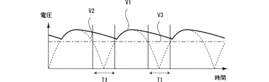
図6(A)は、鋸刃8にかかる負荷(あるいはモータ4にかかる負荷、以下同じ)が一定で、かつ、定回転数制御を行っている場合の本願のモータ4に印加される駆動電圧V1を示したグラフである。図6(A)の横軸は時間を示し、縦軸は電圧を示している。また、整流平滑部61にコンデンサ61Bが設けられていない場合の仮想的な駆動電圧V2(以下仮想電圧V2)を点線で示し、モータ4が目標回転数で回転しているときのモータ4の誘起電圧V3を一点鎖線で示している。
仮想電圧V2は、交流電圧を全波整流した電圧に略等しく、所定の周期で電圧値が0になる。仮に、モータ4が目標回転数で回転している状態で仮想電圧V2がモータ4に印加された場合には、期間T1において、仮想電圧V2が誘起電圧V3以下になり、モータ4へ電流が流れない。このため、モータ4の回転を目標回転数に維持できなくなり、鋸刃8の回転も一定に維持できなくなる。この状態で、被加工材を切断した場合には、切断面の切れ肌が不均一になってしまう。以下の説明では、仮想電圧V2の期間T1のように、駆動電圧が誘起電圧より低くなりモータ4に電流が流れない印加されない期間を無通電期間と呼ぶ。
図6(B)は、容量の小さい平滑コンデンサを搭載した比較例の電動丸鋸の駆動電圧Vc1を示している。平滑コンデンサによって駆動電圧Vc1の最小電圧は0以上になるが、平滑コンデンサの容量が小さいため、期間T2は駆動電圧V1が誘起電圧V3以下になる無通電期間となる。無通電期間T2は、無通電期間T1より短くなるものの、依然として存在している。
本実施の形態では、コンデンサ61Bの総容量を十分に大きい量にしている。そのため図6(A)に示すように、駆動電圧V1は常に誘起電圧V3以上となり、無通電期間は駆動電圧V1に存在しない。即ち、本実施の形態の電動丸鋸1は、駆動電圧V1が、常に誘起電圧V3以上になるような総容量のコンデンサ61Bを備えている。言い換えれば、総容量は、駆動電圧V1が常に誘起電圧V3以上になるような所定の容量に設定されている。本実施の形態では所定の容量は1050マイクロファラッド以上の値に設定される。
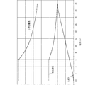
図6(A)は鋸刃8にかかる負荷が一定の場合(なおかつ定回転数制御を行っている場合)について説明した。次に、図7を用いて、鋸刃にかかる負荷が変化する場合における説明する。図7は、モータ4に流れる実効電流(A)(横軸)に対する、モータで発生するトルク(縦軸)と、モータ4の回転数(縦軸)と、モータ4で発生する誘起電圧(縦軸)との関係を示している。尚、図7のグラフは、モータで発生するトルクと、モータの回転数と、モータで発生する誘起電圧とを説明するものである。尚、実際には、コンデンサ61Bの総容量を変化させると、トルクと、回転数と、誘起電圧とは図7に示すグラフから変動する。しかし、ここでは、トルクと、回転数と、誘起電圧との傾向を説明することが目的であるため、これらの変動については詳細を記載していない。尚、以下では実効電流を単に電流と呼ぶ。
図7のトルクは、鋸刃8にかかる負荷(あるいは、モータ4にかかる負荷)の増加とともに増加する。図7に示すように、定回転数制御は、モータ4に流れる実効電流が6A以下で行われている。定回転数制御を行っているとき、鋸刃8にかかる負荷が増加すると、制御部はデューティ比を増加させる。これにより、モータ4に流れる電流が増加する。モータ4に流れる電流が増加するとトルクが増加する。尚、定回転数制御において、モータ4で発生する誘起電圧は略一定である。このように、定回転数制御において、モータ4に流れる電流量は、鋸刃8にかかる負荷(モータ4が発生するトルク)に応じて変化する。
図7における電流が6Aよりも大きい範囲では、モータ4の回転数が徐々に低下している。即ち、この範囲では定回転数制御が行われていない。即ち、この範囲において、デューティ比は最大値(本実施の形態では100パーセント)に設定されているが、鋸刃8にかかる負荷が増加しているため、モータ4の回転数が低下する。このように回転数が低下すると、誘起電圧も低下する。誘起電圧が低下すると、モータ4に流れる電流が増加する。このように、定回転数制御が維持できない範囲(図7において電流が6Aより大きい範囲)においてモータ4の回転数が低下すると、モータ4に流れる電流量が増加する。
以上より、総容量を決定する際には、鋸刃8にかかる負荷(言い換えれば、モータ4が発生するトルク、あるいは、モータ4に流れる電流量)が一定のときの無通電期間の有無について調べるだけでは足りず、当該負荷を変化させたときの無通電期間の有無について調べる必要がある。そのため、本実施の形態のコンデンサ61Bは、以下の2つの条件を満たすように決定される。第1の条件は、定回転数制御が実行されているとき、駆動電圧が常にモータ4で発生した誘起電圧以上になるような総容量を有することである。第2の条件は、定回転数制御が維持できない範囲において、コンデンサ61Bは、モータ4に流れる電流が過電流閾値(最大許容電流値)以下のとき、駆動電圧が常に誘起電圧以上になるような総容量を有することである。
具体的には、総容量は以下のような実験に基づいて決定される。まず、複数の電動丸鋸を用意する。各電動丸鋸は、上記の電動丸鋸1と同じ構成であり、コンデンサの総容量が互いに異なる。ここでは、5つの電動丸鋸についての例を説明する。5つの電動丸鋸に搭載されるコンデンサの総容量は、それぞれ、400、500、600、1050、1400マイクロファラッドである。この5つの電動丸鋸の鋸刃に負荷をかけていき、それぞれの負荷での駆動電圧を測定する。図8~11は、測定した駆動電圧を示しており、それぞれ、モータに流れる電流が4A、6A、12A、18Aのときの結果を示している。モータに流れる電流が、4A、6A、12A、18Aの順で鋸刃8にかかる負荷が増加している。図8~11において、縦軸は電圧(V)を示し、横軸は時間(s)を示している。図8~11では、商用交流電源500を全波整流したときの電圧、および、モータ4で発生する誘起電圧も記載している。
図8は、モータに流れる電流が4Aのときの定回転数制御における駆動電圧を示している。この場合には、総容量が300マイクロファラッド以上であれば、無通電期間は存在しない。従って、5つの電動丸鋸の駆動電圧は、何れも常に誘起電圧以上になる。言い換えれば、総容量が、400、500、600、1050、1400マイクロファラッドの何れの場合でも、駆動電圧は常にモータの誘起電圧以上になる。
図9は、モータに流れる電流が6Aの時の定回転数制御における駆動電圧を示している。ここで、6Aは、定回転数制御においてモータに流れる電流の最大値であり、鋸刃にかかる負荷が、定回転数制御の範囲において最大のときの電流量である。この場合には、総容量が500マイクロファラッド以上であれば、駆動電圧は、常に誘起電圧以上である。従って、総容量が400マイクロファラッドの場合には、無通電期間が存在しているが、総容量が、500、600、1050、1400マイクロファラッドであれば駆動電圧は常にモータの誘起電圧以上になる。
図10は、モータに流れる電流が12Aの時の駆動電圧を記載している。図7に示すように、モータに流れる電流が12Aのとき、デューティ比は最大値(100パーセント)に設定されているが、モータは、目標回転数を維持できず、目標回転数未満で回転する。モータの回転数の低下に伴い誘起電圧が、定回転数制御のときより低下している。この場合には、総容量が400、500、600マイクロファラッドの場合には無通電期間が存在するが、総容量が、1050、1400マイクロファラッドであれば駆動電圧は常にモータの誘起電圧以上になる。
図11は、モータに流れる電流が過電流閾値に一致する18Aの時の駆動電圧を記載している。この場合には、デューティ比が最大値(100パーセント)に設定されているが、モータは、目標回転数未満であって、図10のときの回転数より低い回転数で回転する。モータの回転数の低下に伴い誘起電圧がさらに低下し、モータに流れる電流が増加している。この場合には、総容量が1050マイクロファラッド以上であれば、駆動電圧は常に誘起電圧以上である。従って、総容量が600マイクロファラッド以下の場合には、無通電期間が存在するが、総容量が、1050、1400マイクロファラッドであれば駆動電圧は常にモータの誘起電圧以上になる。尚、図11では、総容量が400、および、500マイクロファラッドの電動丸鋸の駆動電圧については記載していない。
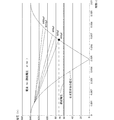
図12は、以上の実験結果をまとめたグラフである。図12において実線で示す5つの曲線は、それぞれ、上記の5つの電動丸鋸に関する駆動電圧に関するものである。詳細には、図12の実線で示す5本の曲線は、それぞれの総容量について、図8~11の実験の結果における最小の駆動電圧(駆動電圧最小値)、つまり放電後の電圧を示している。例えば、図12の総容量400マイクロファラッドのコンデンサに関する駆動電圧において、電流量が4Aのときの駆動電圧最小値は、約70Vであり、図8の400マイクロファラッドのコンデンサにおける時刻約0.007秒の時の電圧値を示している。尚、図12には、参考のためにモータ4の回転数、モータ4で発生する誘起電圧、モータ4が発生するトルクについても記載している。但し、モータ4の回転数、モータ4が発生するトルクの数値については記載せず、電流に対する傾向のみを示している。
以上の実験結果より、まず、図12に示すように、定回転数制御が行われているとき(電流量が6A以下のとき)、何れの駆動電圧の曲線も、電流量の増加に伴って低下していることがわかる。言い換えれば、必要とされるコンデンサ61Bの総容量は、鋸刃8にかかる負荷の増加(即ち、トルクの増加、あるいは、モータに流れる電流量の増加)に伴って増加する。そのため、モータに流れる電流が6Aの時の結果から、500マイクロファラッドが、定回転数制御が実行されているとき、駆動電圧が常にモータで発生する誘起電圧以上になるような総容量として決定される。言い換えれば、定回転数制御における最大電流(6A)のとき駆動電圧が常にモータで発生する駆動電圧以上になるような総容量を決定すれば、定回転数制御が実行されているとき、駆動電圧が常にモータで発生する誘起電圧以上になるような総容量となる。
上述のように電流量が6A以上の区間では定回転数制御が行われていない。図12に示すように、この区間においても、何れの駆動電圧の曲線も電流量の増加に伴って低下していることがわかる。言い換えれば、必要とされるコンデンサ61Bの総容量は、鋸刃8にかかる負荷の増加(即ち、トルクの増加、あるいは、モータに流れる電流量の増加)に伴って増加する。そのため、モータに流れる電流が過電流閾値(最大許容電流値)以下のとき、駆動電圧が常に誘起電圧以上になるような総容量を決定するためには、モータに流れる電流が過電流閾値(最大許容電流値)のときの結果を用いればよい。言い換えれば、モータに流れる電流が過電流閾値のとき、駆動電圧が常に誘起電圧以上になるような総容量を決定すれば、その総容量は、過電流閾値(最大許容電流値)以下のとき、駆動電圧が常に誘起電圧以上になるような総容量である。即ち、1050マイクロファラッドが、モータに流れる電流が過電流閾値(最大許容電流値)以下のとき、駆動電圧が常に誘起電圧以上になるような総容量として決定される。
以上より、電動丸鋸1に搭載するコンデンサ61Bの総容量は、本実施の形態では、1050マイクロファラッドとしたが、それ以上でも良い。
本実施の形態における電動丸鋸1によれば、コンデンサ61Bは、定回転数制御が実行されているとき、駆動電圧が常にモータ4で発生した誘起電圧以上になるような総容量を有している。定回転数制御において、駆動電圧が誘起電圧未満になると、モータ4の回転数を一定にすることができなくなり、モータ4の回転数が不安定になる。回転数が不安定な状態のモータ4を用いて被加工材を切断すると、被加工材の切断面に切れ肌が不均一になる。本実施の形態の電動丸鋸1は、駆動電圧が常に誘起電圧以上であるため、モータ4の回転数が安定しており、従って、切断面の切れ肌が不均一になることを抑制することができる。
また、本実施の形態における電動丸鋸1によれば、コンデンサ61Bは、モータ4に流れる電流が最大許容電流値以下のとき、駆動電圧が常に誘起電圧以上になるような容量を有している。このため、鋸刃8にかかる負荷が増加してもモータ4の回転数が不安定になる。そのため、被加工材を切断するあらゆる状況で切断面の切れ肌が不均一になるのを抑制することができる。
尚、上述のように本実施の形態において、1050マイクロファラッドが、上記第1の条件および第2の条件を満たす総容量の下限値として決定された。従って、コンデンサ61Bの総容量を1050マイクロファラッド以上の任意の容量に設定することが可能であるが、総容量が大きくなりすぎるとコンデンサ61Bのサイズが大きくなる。コンデンサ61Bのサイズが大きくなればなるほど、電動丸鋸1にコンデンサ61Bを収納することが難しくなる。本実施の形態では、上記のように必要となる総容量の下限値を特定し、その下限値もしくは下限値近傍の値に総容量を決定することで、コンデンサ61Bの総容量を過剰に大きくすることを抑制することができる。そのため、コンデンサ61Bのサイズをいたずらに大きくすることを抑制することができる。
本実施の形態におけるコンデンサ61Bの容量は大きいため、コンデンサ61Bの冷却を十分に行う必要がある。本実施の形態では、コンデンサ61Bは、その長手方向が冷却風の流れる方向の上流から下流にかけて延出している。このため、コンデンサ61Bを効果的に冷却することができる。<第2の実施の形態>
第2の実施の形態の電動丸鋸101は、基板ケース71の配置を除き第1の実施の形態の電動丸鋸1と同じである。よって、基板ケース71の配置についてのみ説明する。
図13に示すように、モータハウジング24は、前方向に上方に傾斜して延出する傾斜壁24Tを有している。傾斜壁24Tは底壁24Bの上側に設けられている。基板ケース71は、リブ72を介して、固定壁71Fが傾斜壁24Tに沿うように傾斜壁24Tの上側に固定されている。基板ケース71の固定壁71Fは制御基板6と平行である。従って、制御基板6も傾斜壁24Tに沿って配置されている。
上述のように、ファン43Aは遠心ファンである。ファン43Aは、モータ4の回転軸43と同軸に回転可能である。制御基板6は、回転軸43を中心とした径方向に延出している。詳細には、制御基板6は、回転軸43を中心とした径方向であって、当該制御基板6が設けられた位置の径方向に略平行に配置されている。言い換えれば、制御基板6と回転軸43とは略一直線上に並んでいる。制御基板6と基板ケース71の底面とは平行である。従って、基板ケース71も、回転軸43を中心とした径方向であって、当該基板ケース71が設けられた位置の径方向に略平行に配置されている。また、基板ケース71と回転軸43とは略一直線上に並んでいる。
コンデンサ61Bは、その長手方向が左右方向に延びるように配置されている。言い換えれば、コンデンサ61Bは、その長手方向が冷却風の流れる方向の上流から下流にかけて延出している。コンデンサ61Bは、制御基板6における冷却風の流れる方向の端部に隣接して設けられている。
第2の実施の形態の電動丸鋸101の構成によれば、回転軸43を中心とした径方向であって、当該制御基板6が設けられた位置の径方向に略平行に配置されている。このため、遠心ファン43Aによって発生した冷却風が、制御基板6の上側および下側を円滑に通過することが可能になる。コンデンサ61Bは、制御基板6に関してスイッチング部62と反対側に設けられている。即ち、コンデンサ61Bは、制御基板6の上側に配置され、スイッチング部62は制御基板6の下側に配置されている。コンデンサ61Bとスイッチング部62とは共に熱を発生する素子である。上記のように冷却風は、円滑に制御基板6の上側および下側を通過することが可能であるため、コンデンサ61Bと、スイッチング部62とを効率よく冷却することができる。<第3の実施の形態>
第3の実施の形態の電動丸鋸201は、基板ケース71の配置を除き第1の実施の形態の電動丸鋸1と同じである。よって、基板ケース71の配置についてのみ説明し、他の構成についてはその説明を省略する。
図14に示すように、基板ケース71の固定壁71Fは、コンデンサ61Bがファン43Aに対向するように上下方向に延出している。コンデンサ61Bは、固定壁71Fおよび制御基板6に対してファン43A側に設けられている。また、側壁71Sは、底壁24Bに接触して固定されている。従って、第3の実施の形態ではリブ72は設けられていない。
コンデンサ61Bは、その長手方向が左右方向に延びるように配置されている。言い換えれば、コンデンサ61Bは、その長手方向が冷却風の流れる方向の上流から下流にかけて延出している。コンデンサ61Bは、制御基板6における冷却風の流れる方向の端部に隣接して設けられている。
以上の構成によりファン43Aで発生した冷却風が効果的にコンデンサ61Bの周辺を通過し、コンデンサ61Bを冷却することができる。尚、側壁71Sは、リブ72を介して底壁24Bに固定されていても良い。<第4の実施の形態>
第4の実施の形態の電動丸鋸301は、コンデンサ61Bの代わりにコンデンサ161Bが設けられていることと、基板ケース71の構成とが第1の実施例と異なる。それ以外の構成は第1の実施の形態の電動丸鋸1と同じである。よって、コンデンサ161Bの、および、基板ケース71の構成についてのみ説明し、他の構成についてはその説明を省略する。
図15に示すように、第4の実施の形態において、コンデンサ161Bは1つのみ設けられている。コンデンサ161Bの容量は、第1の実施の形態の2つのコンデンサ61Bの総容量と同じ容量を有する電解コンデンサである。コンデンサ161Bは、制御基板6には搭載されておらず、ハンドル部22の内部に設けられている。詳細には、ハンドル部22の内部に複数のボス22Bが設けられており、円筒形状のコンデンサ161Bの底面がボス22Bによって下方から支持されている。ハンドル部22の内部は、収容室21aと連通している。コンデンサ161Bは、遠心ファン43Aの上部に設けられている。図1に示すように、ハンドル部22は、右端壁22Rを有しており、右端壁22Rには、排気口22aが形成されている。従って、モータハウジング24とハンドル部22において、ファン43Aから排気口22aに至る風路P2が形成されている。ファン43Aで発生した冷却風は、コンデンサ161Bの近傍を通過し、排気口22aから排出される。風路P2は第2の風路の一例である。
コンデンサ161Bは、母線が長手方向となる略円筒形状を有している。コンデンサ161Bは、その長手方向が上下方向に延びるように配置されている。言い換えれば、コンデンサ161Bは、その長手方向が冷却風の流れる方向の上流から下流にかけて延出している。
尚、コンデンサ161Bの電気的な構成は図5で示した構成と同様に、ダイオードブリッジ61Aの前段であって、スイッチング部62の後段にケーブル160(図15)を介して接続されている。
基板ケース71の固定壁71Fは、上下方向に延出している。側壁71Sは、底壁24Bにリブ72を介して固定されている。スイッチング部62、および、ダイオードブリッジ61Aは、制御基板6に対して基板ケース71と反対側に設けられており、回転軸43に対向している。従って、スイッチング部62は、制御基板6と接触していない。
尚、本実施の形態では、制御基板6にコンデンサ161Bが設けられていない。そのため、第1の実施の形態と異なった方法で、制御基板6にスイッチング部62等の素子を搭載している。具体的には、スイッチング部62が制御基板6に対して、ファン43A側に配置されていて、冷却風に晒されるように配置される。
以上の構成によれば、コンデンサ161Bは、ファン43Aの上部に設けられている。ファン43Aで発生した冷却風は、コンデンサ161Bの近傍を通過して排気口22aに排出される。冷却風は、ファン43Aから、一直線上にコンデンサ161Bの近傍まで流れるため、コンデンサ161Bを効率よく冷却することができる。さらに、制御基板6の素子から発せられる熱がコンデンサ161Bに影響しないような配置とすることができる。
また、スイッチング部62はファン43Aの回転軸と対向している。このため、ファン43Aで発生した冷却風が効率よくスイッチング部62の近傍を通過し、スイッチング部62を効率よく冷却することができる。
本発明による電動工具は上述した実施の形態に限定されず、特許請求の範囲に記載した範囲で種々の変形や改良が可能である。例えば、電動工具は電動丸鋸でなくとも、電動ドリルなどの他の電動工具でもよい。
第1の実施の形態のスイッチング部62は、コイルU、V、Wに印加する駆動電圧を切替える動作と、デューティ比に基づいて、駆動電圧を印加する期間を調整する動作を実行している。これに代わって、コイルU、V、Wに印加する駆動電圧を切替える動作のみをスイッチング部62が実行し、スイッチング部62とは別に設けられたスイッチング素子で、駆動電圧を印加する期間の調整を行う動作を実行するようにしてもよい。例えば、このようなスイッチング素子を整流平滑部61と、スイッチング部62との間に設けてもよいし、スイッチング部62とモータ4との間に設けてもよい。
電動丸鋸1は、作業者が目標回転数を選択可能なスイッチを有していてもよい。この場合には、選択可能な目標回転数のうち最大の目標回転数が設定されたときを基準として、モータ4に流れることが許容される最大電流値以下のとき、駆動電圧が常に誘起電圧以上になるような総容量をコンデンサ61Bが有していればよい。
1,101,201,301…電動丸鋸、2…ハウジング、4…モータ、6…制御基板、8…鋸刃、21…本体ハウジング、21a…収容室、24…モータハウジング、31a…吸気口、22a,31b…排気口、43A…ファン、43…回転軸、61…整流平滑部、61A…ダイオードブリッジ、61B,161B…コンデンサ、62…スイッチング部、64…制御部
Claims (12)
- 印加される電圧が誘起電圧以上の時に回転駆動するブラシレスモータと、前記ブラシレスモータに駆動電圧を印加する供給回路と、前記供給回路を制御する制御部と、を備え、前記供給回路は、交流電圧を整流して出力する整流回路と、前記整流回路を経て入力される電圧を平滑するコンデンサと、PWM信号に基づいてスイッチング動作を行うことで、前記駆動電圧を印加する期間を調整可能なスイッチング回路と、を備え、前記制御部は、所定の範囲内のデューティ比を設定し、設定した前記デューティ比の前記PWM信号を前記スイッチング回路に出力して、前記スイッチング動作を制御可能であり、前記制御部は、前記デューティ比を変更して前記ブラシレスモータを目標回転数で回転させるように制御する定回転数制御を実行可能であり、前記コンデンサは、前記定回転数制御が実行されているとき、平滑した電圧が常に誘起電圧以上になるような容量を有していることを特徴とする電動工具。
- 前記ブラシレスモータに流れる電流が最大許容電流値を上回った場合には、前記制御部は、前記供給回路を制御して、前記供給回路から前記ブラシレスモータへの前記駆動電圧の印加を停止し、前記コンデンサは、前記ブラシレスモータに流れる電流が前記最大許容電流値以下のとき、前記駆動電圧が常に前記誘起電圧以上になるような容量を有していることを特徴とする請求項1に記載の電動工具。
- 前記コンデンサの容量は500マイクロファラッド以上であることを特徴とする請求項1に記載の電動工具。
- 前記コンデンサは、並列に接続された複数のコンデンサを有することを特徴とする請求項1乃至3の何れか1項に記載の電動工具。
- 前記ブラシレスモータは回転軸を中心に回転可能なロータを有し、前記回転軸と同軸に回転するファンと、前記ブラシレスモータと、前記供給回路と、前記ファンとを収容するハウジングと、をさらに備え、前記ハウジングは、開口部を有し、前記ハウジング内部に前記ファンから前記開口部に至る風路が形成され、前記コンデンサは、風路上に配置され、前記コンデンサの長手方向は、前記風路を流れる冷却風の流れる方向の上流から下流に向けて延出していることを特徴とする請求項1乃至4の何れか1項に記載の電動工具。
- 前記コンデンサと、前記スイッチング回路とを搭載した基板と、前記基板を収容する基板ケースと、をさらに備え、前記コンデンサは、前記基板ケースの前記開口部側端部に配置されていることを特徴とする請求項5に記載の電動工具。
- 前記スイッチング回路は、前記基板ケースに接触して配置されていることを特徴とする請求項6項に記載の電動工具。
- 前記コンデンサと前記基板との間に充填剤が充填されていることを特徴とする請求項7または8に記載の電動工具。
- 前記ブラシレスモータは回転軸を中心に回転可能なロータを備え、前記回転軸と同軸に回転するファンと、前記スイッチング回路を搭載した基板と、前記ブラシレスモータと、前記供給回路と、前記ファンとを収容するハウジングと、をさらに備え、前記ハウジングは、互いに異なる位置に開口した第1開口部と第2開口部とを有し、前記ファンから第1開口部に至る第1風路と、前記ファンから第2開口部に至る第2風路と、をさらに備え、前記基板は、前記第1風路上に配置されており、前記コンデンサは、前記第2風路上に配置されていることを特徴とする請求項1乃至4の何れか1項に記載の電動工具。
- 前記ハウジングは、前記回転軸の延出方向に関する一端部に設けられ、前記第1開口部を有する第1壁部と、前記延出方向に関する他端部に設けられ、前記第2開口部を有する第2壁部と、を備え、前記第1開口部は、前記ファンと上下方向に関して重なる領域を有し、前記第2開口部は、前記ファンの上方に配置されることを特徴とする請求項9に記載の電動工具。
- 前記ブラシレスモータは回転軸を中心に回転可能なロータを備え、前記回転軸と同軸に回転する遠心ファンと、前記コンデンサが配置された一方の面と、前記スイッチング回路が配置された他方の面とを有する基板と、をさらに備え、前記基板は、前記回転軸の径方向に延出していることを特徴とする請求項1乃至4の何れか1項に記載の電動工具。
- 前記ブラシレスモータは回転軸を中心に回転可能なロータを備え、前記回転軸と同軸に回転する遠心ファンと、前記コンデンサを搭載した基板と、をさらに備え、前記コンデンサは、前記基板に対して前記遠心ファン側に配置されていることを特徴とする請求項1乃至4の何れか1項に記載の電動工具。
Priority Applications (2)
| Application Number | Priority Date | Filing Date | Title |
|---|---|---|---|
| US16/096,449 US10658957B2 (en) | 2016-04-28 | 2017-03-31 | Power tool |
| JP2018514218A JP6656600B2 (ja) | 2016-04-28 | 2017-03-31 | 電動工具 |
Applications Claiming Priority (2)
| Application Number | Priority Date | Filing Date | Title |
|---|---|---|---|
| JP2016091866 | 2016-04-28 | ||
| JP2016-091866 | 2016-04-28 |
Publications (1)
| Publication Number | Publication Date |
|---|---|
| WO2017187890A1 true WO2017187890A1 (ja) | 2017-11-02 |
Family
ID=60161479
Family Applications (1)
| Application Number | Title | Priority Date | Filing Date |
|---|---|---|---|
| PCT/JP2017/013668 Ceased WO2017187890A1 (ja) | 2016-04-28 | 2017-03-31 | 電動工具 |
Country Status (3)
| Country | Link |
|---|---|
| US (1) | US10658957B2 (ja) |
| JP (1) | JP6656600B2 (ja) |
| WO (1) | WO2017187890A1 (ja) |
Cited By (2)
| Publication number | Priority date | Publication date | Assignee | Title |
|---|---|---|---|---|
| JP2019089156A (ja) * | 2017-11-14 | 2019-06-13 | 株式会社マキタ | 携帯用切断機 |
| JP2021030395A (ja) * | 2019-08-28 | 2021-03-01 | 株式会社マキタ | 切断機 |
Families Citing this family (5)
| Publication number | Priority date | Publication date | Assignee | Title |
|---|---|---|---|---|
| JP6824804B2 (ja) * | 2017-04-05 | 2021-02-03 | 株式会社マキタ | 携帯用加工機 |
| EP4070901A4 (en) * | 2019-12-06 | 2023-06-14 | Positec Power Tools (Suzhou) Co., Ltd. | CUTTING TOOL |
| JP7497269B2 (ja) * | 2020-10-26 | 2024-06-10 | 株式会社マキタ | 電動作業機 |
| EP4056323A1 (de) * | 2021-03-11 | 2022-09-14 | Hilti Aktiengesellschaft | Verfahren zum betrieb einer werkzeugmaschine und werkzeugmaschine |
| JPWO2024038822A1 (ja) * | 2022-08-19 | 2024-02-22 |
Citations (11)
| Publication number | Priority date | Publication date | Assignee | Title |
|---|---|---|---|---|
| JPS57177292A (en) * | 1981-04-22 | 1982-10-30 | Hitachi Ltd | Dc brushless motor |
| JPH07327816A (ja) * | 1994-06-08 | 1995-12-19 | Matsushita Electric Ind Co Ltd | 調理器 |
| JPH10146064A (ja) * | 1996-11-07 | 1998-05-29 | Fuji Electric Co Ltd | 電力変換装置用キュービクルの構造 |
| JPH11243668A (ja) * | 1998-02-24 | 1999-09-07 | Toshiba Corp | 密閉型制御装置 |
| JP2010173042A (ja) * | 2009-01-30 | 2010-08-12 | Hitachi Koki Co Ltd | 電動工具 |
| WO2012098780A1 (ja) * | 2011-01-19 | 2012-07-26 | 三洋電機株式会社 | インバータ装置及びこれを搭載した移動体 |
| JP2012196723A (ja) * | 2011-03-18 | 2012-10-18 | Hitachi Koki Co Ltd | 電動工具 |
| JP2013193133A (ja) * | 2012-03-15 | 2013-09-30 | Hitachi Koki Co Ltd | 携帯用電気切断機 |
| JP2014079873A (ja) * | 2012-09-26 | 2014-05-08 | Makita Corp | 電動工具 |
| JP2015100887A (ja) * | 2013-11-26 | 2015-06-04 | 日立工機株式会社 | 電動工具 |
| WO2015129358A1 (ja) * | 2014-02-28 | 2015-09-03 | 日立工機株式会社 | 作業工具 |
Family Cites Families (11)
| Publication number | Priority date | Publication date | Assignee | Title |
|---|---|---|---|---|
| US5540210A (en) * | 1994-02-03 | 1996-07-30 | Jones; Stephen | Adjustable guide for a power saw |
| EP2068428A1 (en) * | 2001-08-29 | 2009-06-10 | Yamazaki Mazak Kabushiki Kaisha | Air cooled linear motor |
| US20050166390A1 (en) * | 2004-01-29 | 2005-08-04 | Gooding Elwyn R. | Adaptive, ergonomic, multi-purpose hand-held tool |
| US7596872B2 (en) * | 2006-07-27 | 2009-10-06 | Robert Bosch Gmbh | Cutting attachment with a removable cover for rotary hand tools |
| DE102007000750A1 (de) * | 2007-09-20 | 2009-04-09 | Hilti Aktiengesellschaft | Handwerkzeugmaschine mit Riemenspannvorrichtung |
| EP2391480B2 (en) | 2009-01-30 | 2018-08-15 | Koki Holdings Kabushiki Kaisha | Power tool |
| JP5490572B2 (ja) * | 2010-03-04 | 2014-05-14 | 株式会社マキタ | 手持ち式切断工具 |
| US10033323B2 (en) | 2011-03-18 | 2018-07-24 | Hitachi Koki Co., Ltd. | Electric power tool |
| JP5879712B2 (ja) * | 2011-03-18 | 2016-03-08 | 日立工機株式会社 | 電動工具 |
| US20160250743A1 (en) | 2013-11-26 | 2016-09-01 | Hitachi Koki Co., Ltd. | Electrical power tool |
| CN108400629B (zh) | 2014-05-18 | 2023-01-24 | 百得有限公司 | 电池组 |
-
2017
- 2017-03-31 US US16/096,449 patent/US10658957B2/en active Active
- 2017-03-31 WO PCT/JP2017/013668 patent/WO2017187890A1/ja not_active Ceased
- 2017-03-31 JP JP2018514218A patent/JP6656600B2/ja active Active
Patent Citations (11)
| Publication number | Priority date | Publication date | Assignee | Title |
|---|---|---|---|---|
| JPS57177292A (en) * | 1981-04-22 | 1982-10-30 | Hitachi Ltd | Dc brushless motor |
| JPH07327816A (ja) * | 1994-06-08 | 1995-12-19 | Matsushita Electric Ind Co Ltd | 調理器 |
| JPH10146064A (ja) * | 1996-11-07 | 1998-05-29 | Fuji Electric Co Ltd | 電力変換装置用キュービクルの構造 |
| JPH11243668A (ja) * | 1998-02-24 | 1999-09-07 | Toshiba Corp | 密閉型制御装置 |
| JP2010173042A (ja) * | 2009-01-30 | 2010-08-12 | Hitachi Koki Co Ltd | 電動工具 |
| WO2012098780A1 (ja) * | 2011-01-19 | 2012-07-26 | 三洋電機株式会社 | インバータ装置及びこれを搭載した移動体 |
| JP2012196723A (ja) * | 2011-03-18 | 2012-10-18 | Hitachi Koki Co Ltd | 電動工具 |
| JP2013193133A (ja) * | 2012-03-15 | 2013-09-30 | Hitachi Koki Co Ltd | 携帯用電気切断機 |
| JP2014079873A (ja) * | 2012-09-26 | 2014-05-08 | Makita Corp | 電動工具 |
| JP2015100887A (ja) * | 2013-11-26 | 2015-06-04 | 日立工機株式会社 | 電動工具 |
| WO2015129358A1 (ja) * | 2014-02-28 | 2015-09-03 | 日立工機株式会社 | 作業工具 |
Cited By (3)
| Publication number | Priority date | Publication date | Assignee | Title |
|---|---|---|---|---|
| JP2019089156A (ja) * | 2017-11-14 | 2019-06-13 | 株式会社マキタ | 携帯用切断機 |
| JP2021030395A (ja) * | 2019-08-28 | 2021-03-01 | 株式会社マキタ | 切断機 |
| JP7315413B2 (ja) | 2019-08-28 | 2023-07-26 | 株式会社マキタ | 切断機 |
Also Published As
| Publication number | Publication date |
|---|---|
| JP6656600B2 (ja) | 2020-03-04 |
| JPWO2017187890A1 (ja) | 2018-12-27 |
| US20190131899A1 (en) | 2019-05-02 |
| US10658957B2 (en) | 2020-05-19 |
Similar Documents
| Publication | Publication Date | Title |
|---|---|---|
| JP6656600B2 (ja) | 電動工具 | |
| EP3293875B1 (en) | Dual-inverter for a brushless motor | |
| US11173584B2 (en) | Waveform shaping in power tool powered by alternating-current power supply | |
| JP5418119B2 (ja) | 作業機械 | |
| EP2626175B1 (en) | Electric power tool | |
| CN107249824B (zh) | 电动工具 | |
| JP7095688B2 (ja) | 電動工具 | |
| EP3213878B1 (en) | Electric work machine | |
| JP2018015865A (ja) | 電動作業機 | |
| WO2015129358A1 (ja) | 作業工具 | |
| US12506422B2 (en) | Motor braking coil for a power tool | |
| JP6508555B2 (ja) | 電動工具 | |
| JP6365907B2 (ja) | 電動工具 | |
| CN114696680A (zh) | 电动工具及其控制方法 | |
| CN114696679A (zh) | 电动工具及其控制方法 | |
| JP2020093369A (ja) | 電動作業機 | |
| CN114696681A (zh) | 电动工具及其控制方法 | |
| JP2020093368A (ja) | 電動作業機 |
Legal Events
| Date | Code | Title | Description |
|---|---|---|---|
| WWE | Wipo information: entry into national phase |
Ref document number: 2018514218 Country of ref document: JP |
|
| NENP | Non-entry into the national phase |
Ref country code: DE |
|
| 121 | Ep: the epo has been informed by wipo that ep was designated in this application |
Ref document number: 17789178 Country of ref document: EP Kind code of ref document: A1 |
|
| 122 | Ep: pct application non-entry in european phase |
Ref document number: 17789178 Country of ref document: EP Kind code of ref document: A1 |