WO2017187704A1 - 部品供給装置、部品供給方法および表面実装機 - Google Patents
部品供給装置、部品供給方法および表面実装機 Download PDFInfo
- Publication number
- WO2017187704A1 WO2017187704A1 PCT/JP2017/004227 JP2017004227W WO2017187704A1 WO 2017187704 A1 WO2017187704 A1 WO 2017187704A1 JP 2017004227 W JP2017004227 W JP 2017004227W WO 2017187704 A1 WO2017187704 A1 WO 2017187704A1
- Authority
- WO
- WIPO (PCT)
- Prior art keywords
- tape
- component supply
- main body
- component
- supply tape
- Prior art date
- Legal status (The legal status is an assumption and is not a legal conclusion. Google has not performed a legal analysis and makes no representation as to the accuracy of the status listed.)
- Ceased
Links
Images


Classifications
-
- H—ELECTRICITY
- H05—ELECTRIC TECHNIQUES NOT OTHERWISE PROVIDED FOR
- H05K—PRINTED CIRCUITS; CASINGS OR CONSTRUCTIONAL DETAILS OF ELECTRIC APPARATUS; MANUFACTURE OF ASSEMBLAGES OF ELECTRICAL COMPONENTS
- H05K13/00—Apparatus or processes specially adapted for manufacturing or adjusting assemblages of electric components
- H05K13/04—Mounting of components, e.g. of leadless components
- H05K13/0417—Feeding with belts or tapes
- H05K13/0419—Feeding with belts or tapes tape feeders
-
- H—ELECTRICITY
- H05—ELECTRIC TECHNIQUES NOT OTHERWISE PROVIDED FOR
- H05K—PRINTED CIRCUITS; CASINGS OR CONSTRUCTIONAL DETAILS OF ELECTRIC APPARATUS; MANUFACTURE OF ASSEMBLAGES OF ELECTRICAL COMPONENTS
- H05K13/00—Apparatus or processes specially adapted for manufacturing or adjusting assemblages of electric components
- H05K13/02—Feeding of components
- H05K13/0215—Interconnecting of containers, e.g. splicing of tapes
-
- H—ELECTRICITY
- H05—ELECTRIC TECHNIQUES NOT OTHERWISE PROVIDED FOR
- H05K—PRINTED CIRCUITS; CASINGS OR CONSTRUCTIONAL DETAILS OF ELECTRIC APPARATUS; MANUFACTURE OF ASSEMBLAGES OF ELECTRICAL COMPONENTS
- H05K13/00—Apparatus or processes specially adapted for manufacturing or adjusting assemblages of electric components
- H05K13/04—Mounting of components, e.g. of leadless components
- H05K13/0404—Pick-and-place heads or apparatus, e.g. with jaws
- H05K13/0408—Incorporating a pick-up tool
- H05K13/0409—Sucking devices
-
- H—ELECTRICITY
- H05—ELECTRIC TECHNIQUES NOT OTHERWISE PROVIDED FOR
- H05K—PRINTED CIRCUITS; CASINGS OR CONSTRUCTIONAL DETAILS OF ELECTRIC APPARATUS; MANUFACTURE OF ASSEMBLAGES OF ELECTRICAL COMPONENTS
- H05K13/00—Apparatus or processes specially adapted for manufacturing or adjusting assemblages of electric components
- H05K13/04—Mounting of components, e.g. of leadless components
- H05K13/0417—Feeding with belts or tapes
-
- H—ELECTRICITY
- H05—ELECTRIC TECHNIQUES NOT OTHERWISE PROVIDED FOR
- H05K—PRINTED CIRCUITS; CASINGS OR CONSTRUCTIONAL DETAILS OF ELECTRIC APPARATUS; MANUFACTURE OF ASSEMBLAGES OF ELECTRICAL COMPONENTS
- H05K13/00—Apparatus or processes specially adapted for manufacturing or adjusting assemblages of electric components
- H05K13/08—Monitoring manufacture of assemblages
- H05K13/086—Supply management, e.g. supply of components or of substrates
-
- H—ELECTRICITY
- H05—ELECTRIC TECHNIQUES NOT OTHERWISE PROVIDED FOR
- H05K—PRINTED CIRCUITS; CASINGS OR CONSTRUCTIONAL DETAILS OF ELECTRIC APPARATUS; MANUFACTURE OF ASSEMBLAGES OF ELECTRICAL COMPONENTS
- H05K13/00—Apparatus or processes specially adapted for manufacturing or adjusting assemblages of electric components
- H05K13/08—Monitoring manufacture of assemblages
- H05K13/087—Equipment tracking or labelling, e.g. tracking of nozzles, feeders or mounting heads
-
- Y—GENERAL TAGGING OF NEW TECHNOLOGICAL DEVELOPMENTS; GENERAL TAGGING OF CROSS-SECTIONAL TECHNOLOGIES SPANNING OVER SEVERAL SECTIONS OF THE IPC; TECHNICAL SUBJECTS COVERED BY FORMER USPC CROSS-REFERENCE ART COLLECTIONS [XRACs] AND DIGESTS
- Y10—TECHNICAL SUBJECTS COVERED BY FORMER USPC
- Y10T—TECHNICAL SUBJECTS COVERED BY FORMER US CLASSIFICATION
- Y10T29/00—Metal working
- Y10T29/53—Means to assemble or disassemble
- Y10T29/5313—Means to assemble electrical device
- Y10T29/53174—Means to fasten electrical component to wiring board, base, or substrate
- Y10T29/53178—Chip component
-
- Y—GENERAL TAGGING OF NEW TECHNOLOGICAL DEVELOPMENTS; GENERAL TAGGING OF CROSS-SECTIONAL TECHNOLOGIES SPANNING OVER SEVERAL SECTIONS OF THE IPC; TECHNICAL SUBJECTS COVERED BY FORMER USPC CROSS-REFERENCE ART COLLECTIONS [XRACs] AND DIGESTS
- Y10—TECHNICAL SUBJECTS COVERED BY FORMER USPC
- Y10T—TECHNICAL SUBJECTS COVERED BY FORMER US CLASSIFICATION
- Y10T29/00—Metal working
- Y10T29/53—Means to assemble or disassemble
- Y10T29/5313—Means to assemble electrical device
- Y10T29/53174—Means to fasten electrical component to wiring board, base, or substrate
- Y10T29/53183—Multilead component
Definitions
- the present invention relates to a component supply device and a component supply method for supplying a component by sending out a component supply tape on which the component is held, and a surface mounter equipped with the component supply device.
- the present invention relates to a technology for introducing a new component supply tape.
- a component supply device is used to supply the above components.
- a carrier tape loading unit that receives a carrier tape (corresponding to the “component supply tape” of the present invention) containing components is provided. Then, the carrier tape introduced into the carrier tape loading unit is temporarily put on standby and then sent to the component pickup unit to supply the components.
- the operator inserts the carrier tape into the carrier tape loading section through an opening (sometimes referred to as an introduction port or an insertion port) provided in the case of the component supply device.
- Carrier tape is introduced into the loading section.
- the opening may enter the blind spot when viewed from the operator. Further, the opening is set to the minimum necessary size. Due to these factors, if the carrier tape is out of order when the carrier tape is inserted into the opening, the carrier tape cannot be allowed to enter the carrier tape loading portion and may be bent or broken.
- parts are supplied in a state where a plurality of parts supply devices are arranged in parallel. Therefore, when inserting the carrier tape into one component supply device, the operator needs to perform the operation of inserting the carrier tape while the other component supply device is adjacent to the one component supply device. Improvement of workability was desired.
- This invention is made in view of the said subject, and it aims at providing the technique which can perform easily the operation
- an introduction region for introducing a component supply tape holding a component is provided in the main body, and the component supply tape introduced into the main body through the introduction region is replaced with the component supply tape.
- a component supply device that supplies components by sending them in the longitudinal direction of the tape, a tape support portion that can be inserted into the introduction area while supporting the component supply tape, and a supported portion that is supported by the tape support portion of the component supply tape
- a clamp mechanism that holds and holds at least a part of the portion with respect to the tape support portion, and the component supply tape is inserted into the introduction region while the component supply tape is held by the clamp mechanism. Is introduced into the main body.
- the second aspect of the present invention is a component supply method, wherein the component supply tape that holds the component is introduced into the main body through the introduction region of the main body, and is introduced into the main body.
- a supply step of feeding the component supply tape in the longitudinal direction of the component supply tape and supplying the component, and the introduction step supports the component supply tape by a tape support portion that can be inserted into the introduction region and supplies the component.
- a third aspect of the present invention is a surface mounter, characterized by comprising the above-described component supply device, and a head unit for mounting the component supplied from the component supply device on a substrate.
- a tape support portion that can be inserted into the introduction region of the main body portion is provided. Then, the supported part of the component supply tape is supported by the tape support part, and at least a part of the supported part is held by the clamp mechanism, the component supply tape is introduced into the introduction region of the main body part together with the tape support part. Inserted. In this way, the component supply tape is always inserted into the main body in a posture supported by the tape support portion, so that the component supply tape is inserted more stably than the conventional technology in which the component supply tape alone is inserted into the main body of the component supply device. The deformation of the component supply tape is prevented. Furthermore, since the component supply tape supported by the tape support portion is inserted into the introduction region while being held by the clamp mechanism, the operation of introducing the component supply tape into the main body portion is simpler than the prior art.
- the support portion of the component supply tape is supported by the tape support portion, and at least part of the supported portion is held by the clamp mechanism, and the tape support portion is introduced into the main body portion.
- the component supply tape is introduced into the main body by inserting it into the main body. For this reason, the introduction operation
- a plurality of constituent elements of each aspect of the present invention described above are not essential, and some or all of the effects described in the present specification are to be solved to solve part or all of the above-described problems.
- technical features included in one embodiment of the present invention described above A part or all of the technical features included in the above-described other aspects of the present invention may be combined to form an independent form of the present invention.
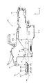
- FIG. 1 shows the surface mounting machine equipped with 1st Embodiment of the components supply apparatus concerning this invention. It is a partial front view of the surface mounter shown in FIG. It is a block diagram which shows the electric constitution of the surface mounter shown in FIG. It is a figure which shows the structure of the feeder which is an example of 1st Embodiment of this invention. It is a perspective view which shows the structure of the component supply tape used for supply of components. It is a perspective view which shows the whole structure of a tape setting part and a set moving mechanism. It is a perspective view which shows the whole structure of a tape setting part and a set moving mechanism. It is a side view of a tape setting part and a set moving mechanism.
- FIG. 1 shows the surface mounting machine equipped with 1st Embodiment of the components supply apparatus concerning this invention. It is a partial front view of the surface mounter shown in FIG. It is a block diagram which shows the electric constitution of the surface mounter shown in FIG. It is a figure which shows the structure of the feeder
- FIG. 7B is a sectional view taken along line BB in FIG. 7A. It is CC sectional view taken on the line in FIG. 7A. It is the figure which looked at the tape set part and the set moving mechanism from the back side of the X-axis direction. It is a figure which shows a tape support member when the tape clamp by a lever member is cancelled
- FIG. 1 is a diagram showing a surface mounter equipped with a first embodiment of a component supply apparatus according to the present invention.
- FIG. 2 is a partial front view of the surface mounter shown in FIG.
- FIG. 3 is a block diagram showing an electrical configuration of the surface mounter shown in FIG.
- This surface mounter 1 is configured to transfer components supplied by a feeder 50 (which corresponds to an example of the “component supply device” of the present invention) mounted on a feeder type supply mechanism 40 to a printed circuit board P1 (“substrate” of the present invention).
- a feeder 50 which corresponds to an example of the “component supply device” of the present invention
- P1 (“substrate” of the present invention).
- the transport conveyor 20 for transporting the printed circuit board P1, and the feeder type supply mechanism 40.
- the component mounting apparatus 30 is provided.
- the base 10 has a rectangular shape in plan view. And with respect to this base 10, the conveyance conveyor 20 is provided in parallel with the longitudinal direction. Further, a backup plate (not shown) for backing up the printed circuit board P1 when the electronic component E1 is mounted on the printed circuit board P1 is provided below the conveyor 20.
- the long side direction of the base 10 left-right direction in FIG. 1
- the transport direction of the printed circuit board P1 by the transport conveyor 20 are defined as the X-axis direction
- the short side direction of the base 10 up and down in FIG. Direction
- the vertical direction vertical direction in FIG. 2 is the Z-axis direction.
- the transport conveyor 20 is disposed at a substantially central position of the base 10 in the Y-axis direction, and transports the printed circuit board P1 along the transport direction (X-axis direction).
- the conveyor 20 includes a pair of conveyor belts 22 that circulate in the conveying direction X.
- the printed circuit board P1 is placed so as to be installed on both conveyor belts 22, and is conveyed in the X-axis direction in this state.
- the printed circuit board P1 is moved from one side (right side shown in FIG. 1) in the transport direction X to the work position on the base 10 along the conveyor belt 22 (position surrounded by a two-dot chain line in FIG. 1). After being carried in, stopped at the work position and mounting the electronic component E1, the work is carried out along the conveyor belt 22 to the other side (left side shown in FIG. 1).
- the component mounting apparatus 30 includes a pair of support frames 31, a head unit 32, and a head unit driving mechanism that drives the head unit 32.
- Each support frame 31 is located on each side of the base 10 in the X-axis direction, and extends in the Y-axis direction.
- the support frame 31 is provided with an X-axis servo mechanism and a Y-axis servo mechanism that constitute a head unit drive mechanism. Then, the X-axis servo mechanism and the Y-axis servo mechanism are operated according to the operation command from the control unit 80 that controls the entire apparatus, so that the head unit 32 moves in the X-axis direction and the Y-axis direction within a certain movable region. Moving.
- the Y-axis servo mechanism has a Y-axis guide rail 33Y, a Y-axis ball screw 34Y, and a Y-axis servo motor 35Y.
- a Y-axis guide rail 33 ⁇ / b> Y extends from each support frame 31.
- a Y-axis ball screw 34Y extends in parallel with each Y-axis guide rail 33Y.
- a Y-axis servomotor 35Y is attached to one end of the Y-axis ball screw 34Y, and is operated in accordance with a drive command from the control unit 80 to be engaged with the Y-axis ball screw 34Y (not shown). (Omitted) moves in the Y-axis direction.
- a head support 36 is fixed to these ball nuts.
- the head support 36 is extended in the X-axis direction.
- the head support 36 is disposed on the ball nut so as to bridge the two Y-axis guide rails 33Y, and is movable along the Y-axis guide rails 33Y. For this reason, when the Y-axis servo motor 35Y is energized and controlled by the control unit 80, the head support 36 fixed to the ball nut and the head unit 32 (to be described later) are moved to the Y-axis guide rail by the forward and backward movement of the ball nut. It moves in the Y-axis direction along 33Y.
- the X-axis servo mechanism has an X-axis guide rail 33X (see FIG. 2), an X-axis ball screw 34X, and an X-axis servo motor 35X.
- an X-axis guide rail 33X extends in the X-axis direction with respect to the head support 36.
- an X-axis ball screw 34X extends in parallel with the X-axis guide rail 33X.
- An X-axis servomotor 35X is attached to one end of the X-axis ball screw 34X, and is operated according to a drive command from the control unit 80 to be engaged with the X-axis ball screw 34X (illustrated). (Omitted) moves in the X-axis direction.
- a head unit 32 is fixed to the ball nut, and moves in the X-axis direction along the X-axis guide rail 33X by the movement of the ball nut.
- the head unit 32 takes out an electronic component E1 supplied by a feeder-type supply mechanism 40 described later and mounts it on the printed circuit board P1. As shown in FIG. 2, a plurality of mounting heads 37 for mounting the electronic component E1 are mounted on the head unit 32 in a row. Each mounting head 37 protrudes downward from the lower surface of the head unit 32, and a suction nozzle 38 for sucking the electronic component E1 by negative pressure is provided at the tip thereof.
- Each mounting head 37 can be rotated around an axis extending in the vertical direction Z by an R-axis servomotor 35R (FIG. 3). Each mounting head 37 can be moved up and down in the vertical direction Z with respect to the frame 32A of the head unit 32 by driving a Z-axis servomotor 35Z (FIG. 3).
- the head unit 32 is provided with a substrate recognition camera C1 (FIG. 2).
- the board recognition camera C ⁇ b> 1 is fixed to the frame 32 ⁇ / b> A of the head unit 32 with the imaging surface facing downward, and moves together with the head unit 32.
- the board recognition camera C1 captures an image at an arbitrary position on the printed board P1 stopped at the work position by moving the head unit 32 in the X-axis direction and the Y-axis direction.
- a component recognition camera C2 (FIG. 1) is fixed in the vicinity of the mounting position of the head unit 32 on the base 10.
- the component recognition camera C2 picks up an image of the electronic component E1 taken out from the component supply position S1 (see FIG. 4 described later) by the mounting head 37, so that the suction posture of each electronic component E1 by the suction nozzle 38 and the like. Recognize
- the control unit 80 includes an arithmetic processing unit 81 composed of a CPU (Central Processing Unit). Connected to the arithmetic processing unit 81 are a motor control unit 82, a storage unit 83, an image processing unit 84, an external input / output unit 85, a feeder communication unit 86, a display unit 88, and an input unit 89. Has been.
- arithmetic processing unit 81 composed of a CPU (Central Processing Unit).
- a motor control unit 82 Connected to the arithmetic processing unit 81 are a motor control unit 82, a storage unit 83, an image processing unit 84, an external input / output unit 85, a feeder communication unit 86, a display unit 88, and an input unit 89.
- a motor control unit 82 Connected to the arithmetic processing unit 81 are connected to the arithmetic processing unit 81. Connected to the arithmetic processing unit 81 are a motor control unit 82,
- the motor control unit 82 drives the X-axis servo motor 35X and the Y-axis servo motor 35Y of the head unit 32 according to a mounting program 83A described later, and drives the Z-axis servo motor 35Z and the R-axis servo motor 35R of each mounting head 32. Let The motor control unit 82 drives the conveyor 20 according to the mounting program 83A.
- the storage unit 83 includes a ROM (Read Only Memory), a RAM (Random Access Memory), and the like, and stores a mounting program 83A and various data 83B.
- the mounting program 83A stored in the storage unit 83 includes board information related to the number of printed circuit boards P1 to be mounted, component information including the number and type of electronic components E1 mounted on the printed circuit board P1, and the like. ing.
- Various data 83 ⁇ / b> B stored in the storage unit 83 includes data regarding the number and types of electronic components E ⁇ b> 1 held in each feeder 50 attached to the feeder type supply mechanism 40.
- the image processing unit 84 takes in image signals output from the board recognition camera C1 and the component recognition camera C2. In the image processing unit 84, analysis of a component image, analysis of a board image, and the like are performed based on the captured image signals from the cameras C1 and C2.
- the external input / output unit 85 is a so-called interface, and is configured to receive detection signals output from various sensors 85A provided in the main body of the surface mounter 1.
- the external input / output unit 85 is configured to perform operation control on various actuators 85 ⁇ / b> B provided in the main body of the surface mounter 1 based on a control signal output from the arithmetic processing unit 81.
- the feeder communication unit 86 is connected to the feeder control unit 59 of each feeder 50 attached to the feeder type supply mechanism 40, and controls each feeder 50 in an integrated manner.
- the feeder controller 59 controls the driving of the front motor 52A and the rear motor 54A in the feeder 50 by control according to the mounting program 83A.
- the feeder controller 59 is connected to a tape sensor (not shown) in the feeder 50, and a detection signal output from the tape sensor is captured. The configuration and operation of the feeder 50 will be described in detail later.
- the display unit 88 is composed of a liquid crystal display device having a display screen, and displays the state of the surface mounter 1 on the display screen.
- the input unit 89 is composed of a keyboard or the like, and accepts external input by manual operation.
- FIG. 4 is a diagram showing a configuration of a feeder which is an example of the first embodiment of the present invention.
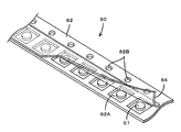
- FIG. 5 is a perspective view showing a configuration of a component supply tape used for supplying components.
- the feeder type supply mechanism 40 is arranged at four places, two places in the X-axis direction on both sides of the conveyor 20 (upper and lower sides in FIG. 1).
- Each feeder type supply mechanism 40 is configured by a collective exchange cart in which a plurality of feeders 50 are detachably mounted in a row.
- Each feeder type supply mechanism 40 is provided with a plurality of reel support portions (not shown), and the component supply tape 60 wound in a reel shape around the reel support portions can be sent to the feeder 50. Yes.
- the component supply tape 60 includes, for example, a carrier tape 62 having a long sheet shape in one direction and a top tape 64 attached to the carrier tape 62 as shown in FIG.
- the carrier tape 62 is provided with hollow component storage portions 62A that open upward at regular intervals in the longitudinal direction of the tape.
- the electronic component E1 is stored and held in each component storage portion 62A in a state of being closed by the top tape 64.
- engagement holes 62B penetrating vertically along the edge are provided at regular intervals.
- the component supply tape 60 configured as described above is sent from the reel support unit and set on the feeder 50, and then conveyed to the component supply position S1 by the operation of the feeder 50 in accordance with the operation command from the control unit 80.
- the electronic component E1 stored in the component storage section 62A can be supplied.
- the electronic component E1 supply side (the side facing the conveyor 20 and the right side in FIG. 4) is the front side, and the opposite side is the rear side.
- the direction orthogonal to both the front-rear direction (Y-axis direction) and the vertical direction (Z-axis direction) of the feeder 50 is defined as the width direction (X-axis direction) of the feeder 50.
- the feeder type supply mechanism 40 is provided with a feeder attachment portion 42, and a plurality of feeders 50 can be attached to the feeder attachment portion 42 in a line in the X-axis direction.
- Each feeder 50 has a main body portion that is long in the front-rear direction (Y-axis direction) as shown in FIG. 4 in order to send the component supply tape 60 holding the electronic component E1 toward the component supply position S1.
- Two sending sections 52 and 54 are provided for 51.
- the cover member 511 is attached to the main-body part 51, in FIG. 4, the cover member 511 is notched and the structure of both the sending parts 52 and 54 is shown in figure.
- the sending section 52 is a front sending section provided in the front portion of the main body 51, and is arranged on the front motor 52 ⁇ / b> A, the front gear group 52 ⁇ / b> B composed of a plurality of gears, and the upper front end of the main body 51.
- the front sprocket 52C and the intermediate sprocket 52D are provided.
- the front motor 52A is electrically connected to the feeder controller 59 as shown in FIG. 3, and the feeder controller 59 drives and controls the front motor 52A in accordance with an operation command from the controller 80. As a result, the front motor 52A operates according to the mounting program 83A.
- the power of the front motor 52A is transmitted to the front sprocket 52C and the intermediate sprocket 52D via the front gear group 52B, and rotates the front sprocket 52C and the intermediate sprocket 52D.
- teeth 52E engaged with the engagement holes 62B of the component supply tape 60 are formed at an equal pitch.
- teeth 52F that are engaged with the engagement holes 62B of the component supply tape 60 are formed at an equal pitch on the outer periphery of the intermediate sprocket 52D.
- the front delivery section 52 rotates the front sprocket 52C and the intermediate sprocket 52D with the teeth 52E of the front sprocket 52C engaged with the engagement holes 62B of the component supply tape 60, so that the front delivery section 52
- the sent-out component supply tape 60 is sent to the component supply position S1 at the front end of the feeder 50.
- An exposure mechanism (not shown) is provided between the intermediate sprocket 52D and the front sprocket 52C to expose the electronic component E1 by cutting or peeling the top tape 64 of the component supply tape 60 that moves between the intermediate sprocket 52D and the front sprocket 52C.
- the rear delivery unit 54 includes a rear motor 54A, a rear gear group 54B composed of a plurality of gears, and a rear sprocket 54C disposed at the upper rear end of the main body 51.
- the rear sending unit 54 is basically configured similarly to the front sending unit 52. That is, the rear motor 54A is electrically connected to the feeder controller 59 as shown in FIG. 3, and the feeder controller 59 drives and controls the rear motor 54A in accordance with an operation command from the controller 80. As a result, the rear motor 54A operates according to the mounting program 83A.
- the power of the rear motor 54A is transmitted to the rear sprocket 54C through the rear gear group 54B, and the teeth 54D of the rear sprocket 54C are engaged with the engagement holes 62B of the component supply tape 60 in the rear side.
- the sprocket 54C rotates.
- the component supply tape 60 is delivered to the front delivery unit 52 via the tape passage 56.
- the component supply tape 60 is set in the rear delivery unit 54 so that the rear delivery unit 54 sends the component supply tape 60 to the front delivery unit 52, and the front delivery unit 52 further moves the component supply tape 60 forward.
- the electronic component E1 accommodated in the component supply tape 60 can be conveyed to the component supply position S1. Further, as described above, in the state where the teeth 52E of the front sprocket 52C are engaged with the engagement holes 62B of the component supply tape 60, the teeth 54D of the rear sprocket 54C are engaged with the engagement holes 62B of the component supply tape 60. It is possible to transport the electronic component E1 to the component supply position S1 only by the front sending section 52 in a free state, that is, in a free state.
- the component supply tape 60 (hereinafter referred to as “preceding tape 60A”) set in advance with respect to the feeder 50 is sent out only by the front sending section 52, and as will be described later, A component supply tape 60 (hereinafter referred to as “subsequent tape 60 ⁇ / b> B”) set to the feeder 50 corresponding to the end portion approaching the feeder 50 is directed to the front sending portion 52 by the rear sending portion 54.
- a component supply tape 60 (hereinafter referred to as “subsequent tape 60 ⁇ / b> B”) set to the feeder 50 corresponding to the end portion approaching the feeder 50 is directed to the front sending portion 52 by the rear sending portion 54.
- the front side sending part 52 and the rear side sending part 54 are provided, and the following three aspects: First tape delivery mode: One component supply tape 60 is sent by the rear delivery unit 54 to the front delivery unit 52, and the same component supply tape 60 is delivered by the front delivery unit 52 to the component supply position S1.
- Second tape delivery mode One component supply tape 60 is delivered to the component supply position S1 only by the front delivery unit 52.
- Third tape delivery mode The subsequent tape 60B is sent to the front delivery unit 52 by the rear delivery unit 54 independently from the delivery of the preceding tape 60A to the component supply position S1 only by the front delivery unit 52. Thus, the component supply tape 60 can be conveyed.
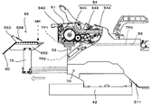
- the main body 51 is provided with a tape passage 56 from the rear sending portion 54 to the front sending portion 52 as shown in FIG.
- An introduction region 53 for introducing the supply tape 60 into the tape passage 56 is provided.
- the introduction region 53 extends in a trumpet shape in the vertical direction Z from the position where it is connected to the tape passage 56 toward the rear end of the main body 51.
- the tip of the tape set portion 55 having a pair of tape support members 551 and 552 is provided so as to be detachable with respect to the introduction region 53.
- the component supply tape 60 is supported from below by the tape support members 551 and 552 by inserting the tape setting portion 55 into the introduction region 53 and can be sent out by the rear sending portion 54.
- the component supply tape 60 is moved to the lower side of the introduction area 53 by pulling out (detaching) the tape setting section 55 from the introduction area 53 and releasing the support by the tape support members 551 and 552, so that the rear supply section 54 is moved. To make it free.
- configurations and operations of the tape setting unit 55 and the set moving mechanism 70 that moves the tape setting unit 55 will be described with reference to the drawings.
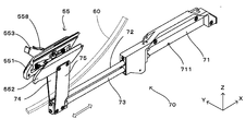
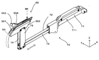
- FIG. 6A and 6B are perspective views showing the entire configuration of the tape setting unit and the set moving mechanism.
- FIG. 6A shows a support release state in which the tape support is released
- FIG. 6B shows a support state in which the tape support is possible.
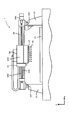
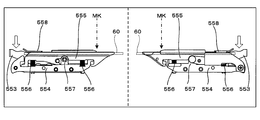
- 7A is a side view of the tape setting unit and the set moving mechanism
- FIG. 7B is a cross-sectional view taken along the line BB in FIG. 7A
- FIG. 7C is a cross-sectional view taken along the line CC in FIG.
- FIG. 7D is a view of the tape setting unit and the set moving mechanism as viewed from the rear side in the X-axis direction (left hand side in FIG. 7A).
- the tape setting unit 55 includes the pair of tape support members 551 and 552 arranged in the width direction (Y-axis direction) of the component supply tape 60. Then, in order to reciprocate the tape supporting members 551 and 552 integrally in the longitudinal direction (X-axis direction) of the tape setting portion 55 and move the tape supporting members 551 and 552 close to and away from each other, the set moving mechanism 70 Is provided.
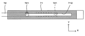
- the set moving mechanism 70 includes a fixing portion 71 fixed to the main body portion 51, and an anti-component supply position side (left hand side in the figure) with respect to the fixing portion 71 in the X-axis direction.
- the shaft members 72 and 73 are provided so as to be able to advance and retreat, and plate members 74 and 75 are provided upright from the front end portions (end portions on the side opposite to the component supply position) of the shaft members 72 and 73.
- a moving space 711 for horizontally moving the end portions of the shaft members 72 and 73 on the component supply position side extends in the X-axis direction.
- the fixed portion 71 has a slit 712 extending in the X-axis direction so that the moving space 711 is desired, and from the end of the shaft member 72 on the component supply position side.
- a protruding portion 721 that protrudes upward is inserted.
- the slit 712 has a substantially L shape as shown in FIG. 7B, and the width direction (Y-axis direction) of the component supply tape 60 is provided on the side opposite to the component supply position of the slit 712 (the left hand side in the figure). ) Is bent at a right angle.
- the groove width of the slit 712 is finished to be slightly wider than the outer diameter of the protruding portion 721, and the shaft member 72 can slide in the X-axis direction while restricting rotational movement except for the bent portion. Yes. Further, when the protruding portion 721 reaches the bent portion, the sliding movement of the shaft member 72 to the anti-component supply position side is stopped there, while the shaft member has an angle range corresponding to the amount of the groove width at the bent portion being widened. 72 is rotatable around a rotation axis parallel to the longitudinal direction.
- the other shaft member 73 is disposed so as to be rotatable around a rotation axis extending in the longitudinal direction vertically below the shaft member 72, and an end portion on the side opposite to the component supply position (left hand side in the figure) is a connecting portion 78.
- the shaft member 72 is connected to the end of the shaft member 72 on the side opposite to the component supply position.
- the connecting portion 78 includes a block member 781 fixed to the shaft member 73 and a protruding member 782 protruding from the shaft member 72 toward the block member 781.
- the lower end portion of the protruding member 782 is finished in a substantially hemispherical shape.
- a concave portion 783 is formed on the upper surface of the block member 781 corresponding to the lower end portion of the protruding member 782. And the shaft members 72 and 73 are mutually connected by the lower end part of the projection member 782 being inserted in the recessed part 783 of the block member 781.
- the shaft members 72 and 73 are rotatable in opposite directions. Then, as will be described later, when the shaft member 72 is rotated clockwise on the paper surface of FIG. 7C by the operation of the operator, the projecting member 782 is displaced in the recess 783 of the block member 781 and the shaft together with the block member 781. The member 73 rotates counterclockwise around the rotation axis extending in the longitudinal direction X.
- the above external force means the force applied by the operator to the tape support members 551 and 552 and the lever member 553 connected to the tape support member 551. Further, when the plate members 74 and 75 are closed and become parallel to each other, the interval between the plate members 74 and 75 is wider than the width of the component supply tape 60, and the components are placed below the tape support members 551 and 552. When the supply tape 60 is positioned, it can move smoothly.
- the tape support members 551 and 552 are separated from the introduction region 53 while being guided by the set moving mechanism 70, they are integrated to support the component supply tape 60 from below (FIG. 6B). In addition, it is possible to switch between an unsupported state (FIG. 6A) in which the support of the component supply tape 60 is released apart from each other.
- the tape support members 551 and 552 have substantially symmetrical structures except for the presence or absence of the lever member 553. Therefore, in the following description, the tape support member 551 to which the lever member 553 is connected will be described, while the tape support member 552 is given the same reference numeral to the same structure and the description thereof is omitted.
- FIG. 8A is a view showing the tape support member when the tape clamp by the lever member is released
- FIG. 8B is a view showing the tape support member when the tape clamp by the lever member is executed.
- the tape support member 551 includes a base member 554 fixed to the upper end of the plate member 76, a movable member 555 that is movably disposed in the vertical direction Z above the base member 554, and an upper surface of the base member 554 that is movable.
- a spring member 556 is disposed between the lower surface of the member 555 and biases the movable member 555 upward with respect to the base member 554.
- the upper surface of the movable member 555 is a tape support surface that supports one end of the component supply tape 60 in the width direction Y from below. More specifically, the lower surface (corresponding to “one main surface” of the present invention) of one end portion (corresponding to an example of “supported part” of the present invention) of the component supply tape 60 is placed on the upper surface of the movable member 555. The tape support is executed. The movable member 555 is biased by the spring member 556 upward, that is, in the surface normal direction of the upper surface of the component supply tape 60 (corresponding to the “other main surface” of the present invention), and on the upper surface of the movable member 555. Is formed with a contact wall that rises slightly upward to restrict the width of the component supply tape 60.
- the abutting walls are also formed on the movable member 555 of the tape support member 552.
- each of the abutting walls is sandwiched between the abutting walls.
- the lower surface ends of the component supply tape 60 in the width direction Y are supported from below by the upper surface regions of the tape support members 551 and 552. Note that the distance between the two abutting walls is larger than the width-direction dimension of the component supply tape 60, and it is possible to effectively prevent the component supply tape 60 from being displaced in the width direction and coming off from the tape set portion 55. It has become.
- the surface supporting the component supply tape 60 does not have a substantially gap between the tape support members 551 and 552.
- the lever member 553 can be pushed down to insert the component supply tape 60 and fit into the sprocket 54C.
- the component supply tape can be easily inserted along the surfaces.
- a shaft support portion 557 is projected from the center of the upper surface of the base member 554, and supports one end of the lever member 553.
- a pin protrudes in the Y-axis direction at a position slightly advanced from the shaft support position to the other end, and is locked to a part of the movable member 555.
- a clamp plate 558 projects from the center of the lever member 553 toward the upper surface (tape support surface) of the movable member 555 in the Y-axis direction. For this reason, when an external force is not acting on the lever member 553, the movable member 555 is pressed upward by the urging force of the spring member 556 and moved to the position shown in FIG. 8A.
- the lever member 553 rotates in accordance with this movement, and the other end portion of the lever member 553 is in a posture of rising obliquely upward.
- the clamp plate 558 is located at an amplifier lamp position away from the tape support surface of the movable member 555 and is in a so-called unclamped state in which the component supply tape 60 is not clamped.
- the lever member 553 when the operator operates to push down the other end of the lever member 553 while resisting the biasing force of the spring member 556, the lever member 553 is centered on the shaft support portion. It is rotated and pushes down the movable member 555 downward. Further, the clamp plate 558 is positioned at a clamp position where the clamp plate 558 contacts the component supply tape 60, and the component supply tape 60 is clamped by sandwiching the component supply tape 60 in the vertical direction with the movable member 555. If the operator releases the lever member 553 from this state, the amplifier lamp state is restored by the biasing force of the spring member 556 (FIG. 8A). In this way, the clamp plate 558 functions as a clamp member that can press the component supply tape 60 against the tape support member 551.
- the lever member 553 functions as a switching unit that switches between the clamped state and the unclamped state, and receives the external force in the Y-axis direction so that the tape set unit 55 is in a tape support state and a support release state in which the tape set unit 55 is released. It also has a support switching function for switching. 6A and 6B, the operator moves the lever member 553 toward the tape support member 552 in the Y-axis direction (right side in FIG. 6A) in a state where the entire tape set portion 55 is pulled out from the main body portion 51.
- the tape support member 551 When a downward force is applied, the tape support member 551 is placed at a position below one end of the component supply tape 60 in the width direction Y (corresponding to the “first support position” of the present invention) as shown in FIG. 6B. Positioned to support one end of the component supply tape 60 from below. Further, in conjunction with the movement of the tape support member 551, the tape support member 552 is positioned below the other end of the component supply tape 60 (corresponding to the “second support position” of the present invention) as shown in FIG. 6B. Then, the other end of the component supply tape 60 is supported from below. Thus, since the pair of tape support members 551 and 552 support the component supply tape 60 in close proximity to each other, that is, in a tape support state, the component supply tape 60 can be stably supported. .
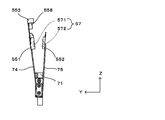
- the connecting portion 57 includes a magnet 571 fixed to the base member 554 of the tape support member 551 and a magnet 572 fixed to the base member 554 of the tape support member 552.
- the magnets 571 and 572 are close to each other and face each other, and the tape supporting members 551 and 552 are connected to each other by a magnetic attractive force generated between them.
- any one of the magnets may be replaced with a magnetic material so as to generate a magnetic attractive force.
- the tape support member 551 When the operator gives the lever member 553 a force larger than the magnetic attraction force in the direction away from the tape support member 552 in the Y-axis direction (upper left direction in FIG. 6B), the tape support member 551 is moved in the width direction Y. It moves to the first non-supporting position away from the first support position in the direction opposite to 552. Further, in conjunction with the movement by the set moving mechanism 70, the tape support member 552 is moved in the width direction Y to the second non-support position away from the second support position in the direction opposite to the tape support member 551. . As a result, the pair of tape support members 551 and 552 are retracted from the lower position of the component supply tape 60, whereby the support of the component supply tape 60 is released.
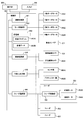
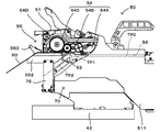
- FIGS. 9A to 9F are diagrams schematically showing a procedure for mounting the component supply tape to the feeder.
- a broken line TP0 in these drawings indicates a delivery path along which the component supply tape 60 is delivered along the tape path 56 to the component supply position S1.
- a broken line TP1 indicates a delivery path formed in the upper space of the introduction area 53 by inserting the tape setting section 55 into the introduction area 53 and sending the component supply tape 60 to the tape path 56 by the rear delivery section 54.
- the tape passage 56 is provided so as to have a downward slope.
- a broken line TP ⁇ b> 2 indicates a delivery path that is formed in the lower space of the introduction region 53 and is used when the component supply tape 60 is delivered to the tape passage 56 only by the front delivery unit 52.
- the component supply tape 60 When the component supply tape 60 is set in the empty feeder 50 with respect to one of the plurality of feeders 50 mounted on the feeder mounting portion 42, the following manual operation is executed by the operator. First, as shown by a white arrow in FIG. 9A, the tape set portion 55 of the feeder 50 is pulled out from the introduction region 53 with the feeder 50 being attached to the feeder attachment portion 42, and is detached from the main body portion 51. In this disengaged state, the component supply tape 60 is sent out from the reel support portion (not shown), the tip of the component supply tape 60 is made to coincide with the mark MK provided at the tip portion of the tape set portion 55, and the connecting portion 57.
- the tip of the component supply tape 60 (supported portion) is placed on the upper surfaces of the pair of tape support members 551 and 552 that are connected to each other.
- the stepped portion provided on the upper surface of each movable member 555 more specifically, the end surface position of the contact wall on the component supply position S1 side is set as the mark MK, and the tape setting portion 55 is set.
- the marks MK functions as an index portion for indicating the tip position in the longitudinal direction of the tip portion (supported portion) of the component supply tape 60 supported by the tape setting portion 55, and is a component for the tape setting portion 55. It becomes easy to always keep the set position and set length of the supply tape 60 constant.
- a structure other than the stepped portion may be used as the mark MK. Further, a mark MK may be newly added to the tape setting unit 55.
- both end portions of the component supply tape 60 are supported from below by the tape support members 551 and 552 in the width direction Y. Subsequently, as shown by an arrow F in FIG. 9B, the component supply tape 60 is clamped by the clamp plate 558 and the movable member 555 when the lever member 553 is pressed, and the tape setting portion 55 is maintained while maintaining the clamped state. It is moved toward the introduction area 53.
- the so-called component supply tape 60 is positioned and clamped at a predetermined position by the tape setting unit 55. Preset processing is performed.
- the tip of the component supply tape 60 is positioned at a position directly below the rear sprocket 54C as shown in FIG. 9C.
- the movable member 555 is moved upward by the biasing force of the spring member 556, and the front end portion of the component supply tape 60 is pressed against the rear sprocket 54C.
- the teeth 54D of the rear sprocket 54C are engaged with the engagement holes 62B of the component supply tape 60, and the lower surface of the component supply tape 60 is elastically supported by the movable member 555. Therefore, the component supply tape 60 can be stably delivered by the rear delivery unit 54 while preventing the pressure exceeding the urging force of the spring member 556 from being applied to the component supply tape 60.
- the control unit 80 accordingly.
- the rear motor 54A is driven to rotate the rear sprocket 54C to feed the front end of the component supply tape 60 to the front side of the feeder 50 and engage with the teeth 52E of the front sprocket 52C (first delivery step).
- the control unit 80 controls each unit of the surface mounter 1 according to the above-described mounting program 83A to supply the electronic component E1 from the feeder 50 and print the electronic component E1 by the head unit 32. Mounted on the surface of the substrate P1.
- the first sending step and the component mounting based on the mounting program 83A are distinguished and executed, it goes without saying that the first sending step may be incorporated into the mounting program 83A.
- the component supply tape 60 is set on the main body 51 of the feeder 50 using the tape setting unit 55, the components are supplied to the main body 51 without deforming the component supply tape 60.
- the tape 60 can be easily introduced.
- the preset process is performed using the mark MK provided in the tape setting unit 55, the introduction can be stably performed.
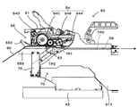
- the feeder 50 While the electronic component E1 is being supplied, that is, during the supply process, the feeder 50 continues to send the component supply tape 60 to the component supply position S1, and the remainder of the component supply tape 60 decreases. To go. Therefore, while the component supply tape 60 continues to be intermittently sent to the component supply position S1, the operator sets the component supply tape 60 as the preceding tape 60A, and until the next component supply by the preceding tape 60A is completed.
- the component supply tape 60 that is, the subsequent tape 60B is set in the feeder 50 by the following manual operation.
- the tape setting portion 55 is pulled out from the introduction area 53 as shown by the white arrow in FIG.
- the lever member 553 is provided in a direction away from the tape support member 552 in the Y-axis direction, and the tape support members 551 and 552 are respectively set to the “first non-support position” and Move to “second unsupported position”. That is, the pair of tape support members 551 and 552 are simultaneously retracted from the position below the component supply tape 60 to release the support of the component supply tape 60.
- the leading tape 60A moves vertically downward in the introduction area 53 due to its own weight, and is separated from the rear sprocket 54C and the delivery path of the preceding tape 60A in the introduction area 53 is switched from the delivery path TP1 to the delivery path TP2. (Tape position switching process).
- the preceding component supply tape 60A is already engaged with the front sprocket 52C, the preceding tape 60A is rotated by rotating the front sprocket 52C even if the preceding tape 60A is separated from the rear sprocket 55. It is possible to continue sending until S1 (second sending step).
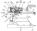
- the feeder controller 59 that has captured the detection signal drives the rear motor 54A and the rear sprocket 54C. Rotate. Thereby, the front-end
- the feeder controller 59 drives the rear motor 54A to rotate at a faster speed than the front motor 52A for a predetermined time. To do. As a result, the succeeding tape 60B is fed out faster than the preceding tape 60A for a predetermined time, and the leading end of the succeeding tape 60B approaches the end of the preceding tape 60A.
- the predetermined time described above is calculated and set in advance as follows. That is, in this embodiment, the speed at which the front motor 52A is rotationally driven is constant, and the control unit 80 determines the speed at which the component supply tape 60 is delivered by the front motor 52A, the tape sensor, the rear sprocket 54C, and the like. The time until the leading end of the succeeding tape 60B reaches the end of the preceding tape 60A is calculated from the distance between the two, and the calculated time can be set as the predetermined time.
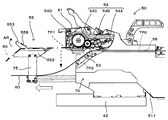
- the front end portion (supported portion) of the component supply tape 60 is supported by the tape setting portion 55 and, as shown in FIG.
- the component supply tape 60 is introduced into the introduction region 53 by inserting the tape setting portion 55 into the introduction region 53 of the main body 51 with the member side) clamped by the clamp plate 558. Accordingly, the component supply tape 60 is always inserted into the main body 51 in a posture supported by the tape setting unit 55, so that the component supply tape 60 is not deformed regardless of the operator's work posture, the presence or absence of blind spots, etc. It can be easily and stably inserted into the main body 51.
- the mark MK is provided on the tape setting unit 55, and the tip position and the introduction region of the component supply tape 60 at the time when the component supply tape 60 is introduced into the main body 51 using the mark MK.
- a so-called preset process is performed in which the tape length in 53 is constant. Accordingly, when the insertion of the tape setting portion 55 into the introduction region 53 is completed, the tip end portion of the component supply tape 60 is positioned at a preset position with respect to the rear sprocket 54C, and the teeth 54D of the rear sprocket 54C.
- the engagement holes 62B of the component supply tape 60 can be stably engaged with each other, and the component supply tape 60 can be reliably delivered by the delivery unit 54.
- the following effects can be obtained by performing the preset processing in this way.
- a sensor for detecting that the tip of the component supply tape 60 has reached a predetermined position is provided, and the component supply tape 60 is manually attached to the main body 51 while the operator monitors the detection of the sensor. Need to be sent to.
- installation of a sensor becomes unnecessary. 9A and 9, after the preset process is performed in a space away from the main body 51, the tape setting portion 55 may be inserted into the introduction region 53 of the main body 51, thereby improving the operator's workability. It can be greatly improved. In particular, in the surface mounter 1 in which a plurality of feeders 50 are adjacently mounted on the feeder mounting portion 42, the above-described effects are remarkable.
- the component supply tape 60 is moved rearward by the movable member 555 with a force corresponding to the urging force of the spring member 556. It is pressed toward the sprocket 54C. As a result, the component supply tape 60 can be sent out stably.
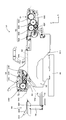
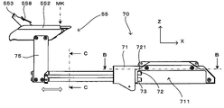
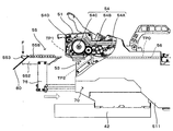
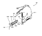
- FIG. 10 is a side view showing a second embodiment of the component supply apparatus according to the present invention.
- FIG. 11 is a partial perspective view of the component supply apparatus shown in FIG.
- the second embodiment is greatly different from the first embodiment in that the tape support portion 551 and 552 are integrated with each other, and the set moving mechanism 70 is not used.
- the part supply tape 60 is sent out from the delivery path TP1 by the fact that the tape set part 55 can be inserted into and removed from the introduction region 53 of the main body part 51 independently and the tape set part 55 is pulled out from the main body part 51.
- the other configuration and operation are basically the same as those in the first embodiment. Therefore, the following description will focus on the differences, and the same configuration and operation will be denoted by the same or corresponding reference numerals and description thereof will be omitted.
- the tape setting unit 55 includes a base member 554, a movable member 555 that is movably disposed in the vertical direction Z above the base member 554, an upper surface of the base member 554, and the movable member 555. And a spring member 556 disposed between the main body 51 and the lower surface.
- the movable member 555 has a tape support surface wider than the width of the component supply tape 60 in the width direction Y. Note that abutting walls (not shown) are erected from the tape support surface at intervals slightly wider than the tape width, and as in the first embodiment, end face positions on the component supply position S1 side of each abutting wall. Is provided as a mark MK.
- a lever member 553 and a clamp plate 558 are provided for the tape set portion 55.
- the setting of the component supply tape 60 to the feeder 50 in the empty state is performed by the same manual operation as in the first embodiment, while the setting of the subsequent tape 60 to the feeder 50 is as follows. It is done like this. That is, the tape setting portion 55 is pulled out from the introduction region 53 as shown by the white arrow in FIGS. 10 and 11 while the preceding tape is continuously fed to the component supply position S1, and is separated from the main body portion 51 independently. Be made. Before the pulling operation, the component supply tape (preceding tape) 60 is supported from below by the tape setting portion 55 inserted into the introducing region 53. However, the support is released by the pulling operation, and the introducing region 53 is caused by its own weight. Move vertically down. That is, the delivery path of the preceding tape 60 in the introduction area 53 is switched from the delivery path TP1 to the delivery path TP2.
- the subsequent tape 60 is preset for the tape set 55 extracted from the main body 51 in this way. That is, after the leading end portion (supported portion) of the succeeding tape 60 is placed on the upper surface of the movable member 55 and supported from below by the tape setting portion 55 while the leading end of the succeeding tape 60 is aligned with the mark MK, When the lever member 553 is pressed, the tip of the subsequent tape 60 is clamped by the clamp plate 558 and the movable member 555. Then, the tape setting portion 55 is inserted into the introduction region 53 of the main body portion 51 to complete the setting of the subsequent tape 60.
- the preset tape setting portion 55 is inserted into the introduction region 53 of the main body 51 and the component supply tape 60 is set, as in the first embodiment, The delivery of the component supply tape 60 by the delivery unit 54 can be performed reliably.
- the preset processing is performed in a state where the tape set unit 55 is pulled out from the main body 51 and completely separated. The preset process can be performed even at a distant position, and the workability of the preset process can be improved.
- the electronic component E1 corresponds to an example of the “component” of the present invention
- the feeder 50 corresponds to an example of the “component supply device” of the present invention
- the tape setting portion 55 and the set moving mechanism 70 correspond to examples of the “tape support portion” and the “moving portion” of the present invention, respectively.
- the lever member 553 and the clamp plate 558 correspond to examples of the “switching unit” and the “clamp member” of the present invention, respectively, and these function as the “clamp mechanism” of the present invention.
- the movable member 555 corresponds to an example of the “support member” of the present invention.
- the spring member 566 corresponds to an example of the “biasing member” of the present invention.
- the mark MK corresponds to an example of the “index part” of the present invention.
- the preset process corresponds to an example of the “introduction process” of the present invention.
- the present invention is not limited to the above embodiment, and various modifications can be made to the above without departing from the spirit of the present invention.
- the two shaft members 72, 73 and the connecting portion 78 are configured to open the pair of tape support members 551, 552. Is not limited to this, and a conventionally known double-open structure may be used.
- the shaft members 72 and 73 may be arranged in a double tubular shape.
- a latch mechanism may be incorporated into the rotation mechanism of the lever member 553 so that the clamp state (FIG. 8B) returns to the amplifier lamp state (FIG. 8A) via a latch release operation.
- the tape support members 551 and 552 in order to move the tape support members 551 and 552 at the same time, as shown in FIG. 7C, an uneven structure is provided in the connecting portion 78, but the tape support members 551 and 552 are formed by other structures. May be moved simultaneously. Further, the tape support member 552 may be moved slightly behind the movement of the tape support member 551 so that the tape support members 551 and 552 are opened in both directions.
- the subsequent tape 60B is automatically sent during component supply by the preceding tape 60A, and the leading end of the subsequent tape 60B is brought close to the end portion of the preceding tape 60A so as to suppress breaks in component supply.
- the present invention is applied to the auto loading feeder, the appropriate object of the present invention is not limited to this, and the present invention is generally applied to the component supply technology for supplying the electronic component E1 by feeding the component supply tape 60 in the longitudinal direction. Can be applied.
- the tape support portion has a support member that supports one main surface of the component supply tape
- the clamp mechanism is A clamp member capable of pressing the component supply tape, a clamp position where the clamp member presses and holds the component supply tape against the support member, and the clamp member is separated from the support member to release the holding of the component supply tape.
- You may comprise so that it may have a switching part which moves a clamp member between unclamp positions, and switches holding
- the tape support portion may be configured to have a biasing member that biases the support member in the surface normal direction of the other main surface of the component supply tape.
- the tape support portion may be configured to have an index portion that indicates the tip position in the longitudinal direction of the supported portion supported by the tape support portion, and the position of the component supply tape with respect to the tape support portion is determined. It can be made constant. As a result, the tip position of the component supply tape at the time when it is introduced into the main body can be stabilized, and the subsequent supply of the component supply tape within the main body can be performed reliably.
- the moving part which inserts / removes with respect to an introduction area
- the tape support part may be configured to be separated from the main body part so that it can be inserted into and removed from the introduction region. In this case, not only the position near the main body part but also the position away from the main body part. Even so, it is possible to perform a support operation by the tape support portion of the component supply tape and a clamp operation by the clamp mechanism, and it is possible to improve these workability.
- the present invention can be applied to a component supply technology for supplying a component by sending a component supply tape in the longitudinal direction thereof, and a surface mounter for mounting a component supplied by the technology on a substrate in general.
Landscapes
- Engineering & Computer Science (AREA)
- Manufacturing & Machinery (AREA)
- Microelectronics & Electronic Packaging (AREA)
- Supply And Installment Of Electrical Components (AREA)
Priority Applications (3)
| Application Number | Priority Date | Filing Date | Title |
|---|---|---|---|
| US16/092,656 US11606891B2 (en) | 2016-04-28 | 2017-02-06 | Component supply device and surface mounting machine |
| DE112017001068.3T DE112017001068T5 (de) | 2016-04-28 | 2017-02-06 | Bauteilzuführungsvorrichtung, Bauteilzuführungsverfahren und Oberflächenmontagemaschine |
| CN201780008779.3A CN108605430B (zh) | 2016-04-28 | 2017-02-06 | 元件供给装置、元件供给方法及表面安装机 |
Applications Claiming Priority (2)
| Application Number | Priority Date | Filing Date | Title |
|---|---|---|---|
| JP2016-090289 | 2016-04-28 | ||
| JP2016090289A JP6554440B2 (ja) | 2016-04-28 | 2016-04-28 | 部品供給装置、部品供給方法および表面実装機 |
Publications (1)
| Publication Number | Publication Date |
|---|---|
| WO2017187704A1 true WO2017187704A1 (ja) | 2017-11-02 |
Family
ID=60160248
Family Applications (1)
| Application Number | Title | Priority Date | Filing Date |
|---|---|---|---|
| PCT/JP2017/004227 Ceased WO2017187704A1 (ja) | 2016-04-28 | 2017-02-06 | 部品供給装置、部品供給方法および表面実装機 |
Country Status (5)
| Country | Link |
|---|---|
| US (1) | US11606891B2 (enExample) |
| JP (1) | JP6554440B2 (enExample) |
| CN (1) | CN108605430B (enExample) |
| DE (1) | DE112017001068T5 (enExample) |
| WO (1) | WO2017187704A1 (enExample) |
Families Citing this family (7)
| Publication number | Priority date | Publication date | Assignee | Title |
|---|---|---|---|---|
| JP6554440B2 (ja) * | 2016-04-28 | 2019-07-31 | ヤマハ発動機株式会社 | 部品供給装置、部品供給方法および表面実装機 |
| JP6929189B2 (ja) | 2017-10-13 | 2021-09-01 | Toyo Tire株式会社 | 空気入りタイヤ |
| US11974402B2 (en) | 2018-06-27 | 2024-04-30 | Yamaha Hatsudoki Kabushiki Kaisha | Component supply device |
| JP7199549B2 (ja) * | 2019-08-27 | 2023-01-05 | ヤマハ発動機株式会社 | 部品補給支援装置、部品実装システム、部品補給支援方法 |
| CN114041330B (zh) * | 2019-08-27 | 2023-10-17 | 雅马哈发动机株式会社 | 元件安装机、带式送料器、带放置单元 |
| US12227380B2 (en) * | 2020-03-03 | 2025-02-18 | Fuji Corporation | Wind-up drum, tape feeder, and component mounting machine |
| CN112272512B (zh) * | 2020-10-23 | 2021-10-19 | 湖南大学 | 一种smd用贴装系统 |
Citations (4)
| Publication number | Priority date | Publication date | Assignee | Title |
|---|---|---|---|---|
| JP2002533943A (ja) * | 1998-12-22 | 2002-10-08 | マイデータ オートメーション アクチボラグ | 部品機械のテープ・ガイドおよびマガジン |
| JP2003188578A (ja) * | 2001-12-18 | 2003-07-04 | Matsushita Electric Ind Co Ltd | テープフィーダ |
| JP2008041732A (ja) * | 2006-08-02 | 2008-02-21 | Matsushita Electric Ind Co Ltd | テープフィーダ |
| WO2014002912A1 (ja) * | 2012-06-29 | 2014-01-03 | 株式会社日立ハイテクインスツルメンツ | 電子部品装着装置及び電子部品装着方法 |
Family Cites Families (12)
| Publication number | Priority date | Publication date | Assignee | Title |
|---|---|---|---|---|
| US4952113A (en) * | 1988-11-14 | 1990-08-28 | Tenryu Technics Co., Ltd. | Chip feeder for chip mounter |
| WO2003103362A1 (en) * | 2002-06-03 | 2003-12-11 | Assembleon N. V. | Component supplying device |
| TWI236321B (en) * | 2003-04-10 | 2005-07-11 | Protec Co Ltd | Tape feeder for chip mounters |
| US7243828B2 (en) * | 2004-11-12 | 2007-07-17 | Samsung Techwin Co., Ltd. | Tape feeder for component mounter and method of automatically setting tape initial position by the same |
| JP4762193B2 (ja) * | 2007-04-27 | 2011-08-31 | パナソニック株式会社 | 部品供給装置 |
| US8678065B2 (en) | 2010-03-30 | 2014-03-25 | Sts Co., Ltd. | Carrier tape feeder |
| JP5423644B2 (ja) * | 2010-10-14 | 2014-02-19 | パナソニック株式会社 | テープフィーダおよびテープフィーダにおけるテープ装着方法 |
| JP5909643B2 (ja) * | 2012-04-13 | 2016-04-27 | パナソニックIpマネジメント株式会社 | テープフィーダおよびテープフィーダにおける設定情報の表示方法 |
| JP6002937B2 (ja) * | 2012-11-28 | 2016-10-05 | パナソニックIpマネジメント株式会社 | テープフィーダ |
| EP3041332B1 (en) * | 2013-08-26 | 2018-01-10 | Fuji Machine Mfg. Co., Ltd. | Feeder |
| JP6174547B2 (ja) | 2014-10-30 | 2017-08-02 | 株式会社小野測器 | 分布図表示装置及び方法 |
| JP6554440B2 (ja) * | 2016-04-28 | 2019-07-31 | ヤマハ発動機株式会社 | 部品供給装置、部品供給方法および表面実装機 |
-
2016
- 2016-04-28 JP JP2016090289A patent/JP6554440B2/ja active Active
-
2017
- 2017-02-06 WO PCT/JP2017/004227 patent/WO2017187704A1/ja not_active Ceased
- 2017-02-06 CN CN201780008779.3A patent/CN108605430B/zh active Active
- 2017-02-06 DE DE112017001068.3T patent/DE112017001068T5/de active Pending
- 2017-02-06 US US16/092,656 patent/US11606891B2/en active Active
Patent Citations (4)
| Publication number | Priority date | Publication date | Assignee | Title |
|---|---|---|---|---|
| JP2002533943A (ja) * | 1998-12-22 | 2002-10-08 | マイデータ オートメーション アクチボラグ | 部品機械のテープ・ガイドおよびマガジン |
| JP2003188578A (ja) * | 2001-12-18 | 2003-07-04 | Matsushita Electric Ind Co Ltd | テープフィーダ |
| JP2008041732A (ja) * | 2006-08-02 | 2008-02-21 | Matsushita Electric Ind Co Ltd | テープフィーダ |
| WO2014002912A1 (ja) * | 2012-06-29 | 2014-01-03 | 株式会社日立ハイテクインスツルメンツ | 電子部品装着装置及び電子部品装着方法 |
Also Published As
| Publication number | Publication date |
|---|---|
| US11606891B2 (en) | 2023-03-14 |
| DE112017001068T5 (de) | 2018-11-29 |
| JP2017199832A (ja) | 2017-11-02 |
| US20190133009A1 (en) | 2019-05-02 |
| CN108605430A (zh) | 2018-09-28 |
| CN108605430B (zh) | 2020-04-28 |
| JP6554440B2 (ja) | 2019-07-31 |
Similar Documents
| Publication | Publication Date | Title |
|---|---|---|
| JP6554440B2 (ja) | 部品供給装置、部品供給方法および表面実装機 | |
| JPWO2016117091A1 (ja) | フィーダ装置 | |
| JP2020017768A (ja) | 部品実装機 | |
| CN107950083B (zh) | 追加型带盘保持装置 | |
| JP5903664B2 (ja) | テープフィーダおよびテープ送り方法 | |
| US20210251113A1 (en) | Exchange device | |
| JP6431048B2 (ja) | フィーダ | |
| EP2741596B1 (en) | Electronic component mounting method and surface mounting apparatus | |
| JP4804296B2 (ja) | 部品供給装置及び表面実装機 | |
| JP6049741B2 (ja) | フィーダ型部品供給装置 | |
| WO2018087857A1 (ja) | 部品供給装置、表面実装機、及び部品供給方法 | |
| JP6661460B2 (ja) | 部品供給装置、部品供給方法および表面実装機 | |
| JP6346068B2 (ja) | 部品供給装置、表面実装機、及び部品の供給方法 | |
| EP3809809B1 (en) | Exchange device | |
| JP7590551B2 (ja) | フィーダ及び部品実装機 | |
| JP7611396B2 (ja) | 部品装着機 | |
| JP7181058B2 (ja) | 部品実装機、部品補給作業支援方法 | |
| JP5877211B2 (ja) | 電子部品供給装置 | |
| JP2000114781A (ja) | テープフィーダおよびテープフィーダにおけるリール交換方法 | |
| JP7532684B2 (ja) | テープ先端処理方法およびテープ先端処理治具 | |
| JP6869734B2 (ja) | 表面実装機、表面実装機のノズル交換プログラムおよび表面実装機のノズルの交換方法 | |
| JP7638399B2 (ja) | 基板作業装置及び余剰バックアップピンの管理方法 | |
| JP2018010998A (ja) | フィーダ装置 | |
| JP7250965B2 (ja) | 部品実装プログラム |
Legal Events
| Date | Code | Title | Description |
|---|---|---|---|
| 121 | Ep: the epo has been informed by wipo that ep was designated in this application |
Ref document number: 17788993 Country of ref document: EP Kind code of ref document: A1 |
|
| 122 | Ep: pct application non-entry in european phase |
Ref document number: 17788993 Country of ref document: EP Kind code of ref document: A1 |