WO2017183295A1 - ワイヤソー装置の製造方法及びワイヤソー装置 - Google Patents
ワイヤソー装置の製造方法及びワイヤソー装置 Download PDFInfo
- Publication number
- WO2017183295A1 WO2017183295A1 PCT/JP2017/006980 JP2017006980W WO2017183295A1 WO 2017183295 A1 WO2017183295 A1 WO 2017183295A1 JP 2017006980 W JP2017006980 W JP 2017006980W WO 2017183295 A1 WO2017183295 A1 WO 2017183295A1
- Authority
- WO
- WIPO (PCT)
- Prior art keywords
- wire
- long roller
- surface roughness
- roughness rmax
- supply reel
- Prior art date
- Legal status (The legal status is an assumption and is not a legal conclusion. Google has not performed a legal analysis and makes no representation as to the accuracy of the status listed.)
- Ceased
Links
Images



Classifications
-
- B—PERFORMING OPERATIONS; TRANSPORTING
- B24—GRINDING; POLISHING
- B24B—MACHINES, DEVICES, OR PROCESSES FOR GRINDING OR POLISHING; DRESSING OR CONDITIONING OF ABRADING SURFACES; FEEDING OF GRINDING, POLISHING, OR LAPPING AGENTS
- B24B27/00—Other grinding machines or devices
- B24B27/06—Grinders for cutting-off
- B24B27/0633—Grinders for cutting-off using a cutting wire
-
- B—PERFORMING OPERATIONS; TRANSPORTING
- B24—GRINDING; POLISHING
- B24B—MACHINES, DEVICES, OR PROCESSES FOR GRINDING OR POLISHING; DRESSING OR CONDITIONING OF ABRADING SURFACES; FEEDING OF GRINDING, POLISHING, OR LAPPING AGENTS
- B24B27/00—Other grinding machines or devices
- B24B27/06—Grinders for cutting-off
-
- B—PERFORMING OPERATIONS; TRANSPORTING
- B24—GRINDING; POLISHING
- B24B—MACHINES, DEVICES, OR PROCESSES FOR GRINDING OR POLISHING; DRESSING OR CONDITIONING OF ABRADING SURFACES; FEEDING OF GRINDING, POLISHING, OR LAPPING AGENTS
- B24B29/00—Machines or devices for polishing surfaces on work by means of tools made of soft or flexible material with or without the application of solid or liquid polishing agents
- B24B29/02—Machines or devices for polishing surfaces on work by means of tools made of soft or flexible material with or without the application of solid or liquid polishing agents designed for particular workpieces
- B24B29/04—Machines or devices for polishing surfaces on work by means of tools made of soft or flexible material with or without the application of solid or liquid polishing agents designed for particular workpieces for rotationally symmetrical workpieces, e.g. ball-, cylinder- or cone-shaped workpieces
-
- B—PERFORMING OPERATIONS; TRANSPORTING
- B24—GRINDING; POLISHING
- B24B—MACHINES, DEVICES, OR PROCESSES FOR GRINDING OR POLISHING; DRESSING OR CONDITIONING OF ABRADING SURFACES; FEEDING OF GRINDING, POLISHING, OR LAPPING AGENTS
- B24B5/00—Machines or devices designed for grinding surfaces of revolution on work, including those which also grind adjacent plane surfaces; Accessories therefor
- B24B5/36—Single-purpose machines or devices
- B24B5/363—Single-purpose machines or devices for grinding surfaces of revolution in situ
-
- B—PERFORMING OPERATIONS; TRANSPORTING
- B24—GRINDING; POLISHING
- B24B—MACHINES, DEVICES, OR PROCESSES FOR GRINDING OR POLISHING; DRESSING OR CONDITIONING OF ABRADING SURFACES; FEEDING OF GRINDING, POLISHING, OR LAPPING AGENTS
- B24B5/00—Machines or devices designed for grinding surfaces of revolution on work, including those which also grind adjacent plane surfaces; Accessories therefor
- B24B5/36—Single-purpose machines or devices
- B24B5/37—Single-purpose machines or devices for grinding rolls, e.g. barrel-shaped rolls
-
- B—PERFORMING OPERATIONS; TRANSPORTING
- B28—WORKING CEMENT, CLAY, OR STONE
- B28D—WORKING STONE OR STONE-LIKE MATERIALS
- B28D5/00—Fine working of gems, jewels, crystals, e.g. of semiconductor material; apparatus or devices therefor
- B28D5/04—Fine working of gems, jewels, crystals, e.g. of semiconductor material; apparatus or devices therefor by tools other than rotary type, e.g. reciprocating tools
-
- B—PERFORMING OPERATIONS; TRANSPORTING
- B28—WORKING CEMENT, CLAY, OR STONE
- B28D—WORKING STONE OR STONE-LIKE MATERIALS
- B28D5/00—Fine working of gems, jewels, crystals, e.g. of semiconductor material; apparatus or devices therefor
- B28D5/04—Fine working of gems, jewels, crystals, e.g. of semiconductor material; apparatus or devices therefor by tools other than rotary type, e.g. reciprocating tools
- B28D5/045—Fine working of gems, jewels, crystals, e.g. of semiconductor material; apparatus or devices therefor by tools other than rotary type, e.g. reciprocating tools by cutting with wires or closed-loop blades
-
- H—ELECTRICITY
- H10—SEMICONDUCTOR DEVICES; ELECTRIC SOLID-STATE DEVICES NOT OTHERWISE PROVIDED FOR
- H10P—GENERIC PROCESSES OR APPARATUS FOR THE MANUFACTURE OR TREATMENT OF DEVICES COVERED BY CLASS H10
- H10P52/00—Grinding, lapping or polishing of wafers, substrates or parts of devices
-
- B—PERFORMING OPERATIONS; TRANSPORTING
- B65—CONVEYING; PACKING; STORING; HANDLING THIN OR FILAMENTARY MATERIAL
- B65H—HANDLING THIN OR FILAMENTARY MATERIAL, e.g. SHEETS, WEBS, CABLES
- B65H2701/00—Handled material; Storage means
- B65H2701/30—Handled filamentary material
- B65H2701/36—Wires
-
- B—PERFORMING OPERATIONS; TRANSPORTING
- B65—CONVEYING; PACKING; STORING; HANDLING THIN OR FILAMENTARY MATERIAL
- B65H—HANDLING THIN OR FILAMENTARY MATERIAL, e.g. SHEETS, WEBS, CABLES
- B65H54/00—Winding, coiling, or depositing filamentary material
- B65H54/02—Winding and traversing material on to reels, bobbins, tubes, or like package cores or formers
- B65H54/28—Traversing devices; Package-shaping arrangements
-
- B—PERFORMING OPERATIONS; TRANSPORTING
- B65—CONVEYING; PACKING; STORING; HANDLING THIN OR FILAMENTARY MATERIAL
- B65H—HANDLING THIN OR FILAMENTARY MATERIAL, e.g. SHEETS, WEBS, CABLES
- B65H59/00—Adjusting or controlling tension in filamentary material, e.g. for preventing snarling; Applications of tension indicators
- B65H59/10—Adjusting or controlling tension in filamentary material, e.g. for preventing snarling; Applications of tension indicators by devices acting on running material and not associated with supply or take-up devices
Definitions
- the present invention relates to a wire saw cutting technique, and more particularly, to a method for manufacturing a wire saw apparatus and a wire saw apparatus applicable to a wafer cutting process or the like that forms (slices) a workpiece, for example, a silicon semiconductor single crystal ingot.
- a plurality of silicon semiconductor wafers are obtained by thinly cutting a silicon semiconductor single crystal ingot pulled up by a single crystal pulling apparatus in the direction perpendicular to the axis using an inner peripheral slicer.
- a cutting method using a wire saw has attracted attention in recent years.
- the workpiece is pressed against a wire row spirally wound between a plurality of wire guides (main rollers), and the wire is moved while supplying slurry to the contact portion between the workpiece and the wire.
- Is a method of cutting a workpiece into a wafer shape for example, Patent Document 1).
- a large number of wafers for example, several hundred wafers
- a long roller, a tension arm, etc. are arranged between the wire supply reel and the wire guide, and the wire extended from the wire supply reel is Passes on the long roller while moving in the axial direction of the long roller. At this time, the wire that has not moved smoothly in the axial direction of the long roller may suddenly return to its original position (position where the length of the running wire is shortest).
- the present invention has been made in view of the above-described problems of the prior art.
- the wire extended from the wire supply reel moves smoothly on the long roller in the axial direction, and the tension arm moves out of the control range. It is an object of the present invention to provide a method of manufacturing a wire saw device and a wire saw device that can prevent a large shake.
- a wire supply reel that extends a wire
- a long roller that allows the wire extending from the wire supply reel to pass over the surface, and the wire around A plurality of wire guides wound spirally, a wire take-up reel for winding the wire, and arranged between the wire supply reel and the wire guide, and operate within a set control angle ⁇ A (°).
- a tension arm that applies tension to the wire, and the wire can pass over the long roller while moving in the axial direction of the long roller, Measuring the surface roughness Rmax of the long roller;
- a step of measuring an angle a (°) of the tension arm when the angle of the tension arm swings out of the set control angle range when the wire is extended from the wire supply reel.
- the wire extended from the wire supply reel can smoothly move on the long roller in the axial direction, the tension arm can be prevented from swinging out of the control range, and the wire can be prevented from being disconnected.
- a wire saw device can be manufactured.
- the surface roughness Rmax is the maximum sectional height of a sectional curve measured according to JIS B0601.
- a urethane roller having a Shore hardness of A80 to 96 it is preferable to use a urethane roller having a Shore hardness of A80 to 96 as the long roller.
- the wire can easily move smoothly, the shape change and shape deterioration of the long roller can be reduced, and the number of service life can be improved.
- the Shore hardness By setting the Shore hardness to A80 or higher, deformation of the long roller can be prevented and the number of uses can be improved, and by setting the Shore hardness to A96 or less, processing (polishing) to reduce the surface roughness can be performed efficiently. Can do.
- the surface roughness Rmax of the long roller is made equal to or less than the calculated numerical value R2 by polishing the surface of the long roller with a polishing film of # 800 to 3000.
- the surface roughness Rmax of the long roller can be more reliably set to R2 or less. Moreover, by setting it as # 3000 or less, it can prevent that a polishing film clogs and can grind
- a wire supply reel that extends a wire
- a long roller that allows the wire extending from the wire supply reel to pass over the surface, and a plurality of wires that are wound spirally around the wire
- the wire guide, the wire take-up reel that winds up the wire, the wire guide reel, and the wire guide reel are arranged between the wire guide reel and the wire guide and controlled to operate within a set control angle ⁇ A (°)
- a wire saw device that has a tension arm that applies tension to the wire, and the wire can pass on the long roller while moving in the axial direction of the long roller,
- the long roller has a surface roughness Rmax of 21 ⁇ m or less.
- the long roller is preferably made of urethane having a Shore hardness of A80 to 96.
- the wire can easily move smoothly, the shape change and shape deterioration of the long roller can be reduced, and the number of service life can be improved.
- the Shore hardness By setting the Shore hardness to A80 or higher, deformation of the long roller can be prevented and the number of uses can be improved, and by setting the Shore hardness to A96 or less, processing (polishing) to reduce the surface roughness can be performed efficiently. Can do.
- the wire extended from the wire supply reel is smoothly moved in the axial direction on the long roller, and the tension arm is prevented from swinging greatly outside the control range.
- the wire saw device can prevent the wire from being disconnected.
- the present invention is not limited to this.
- the wire saw in which the wire extended from the wire supply reel passes while moving on the long roller in the axial direction, the wire that did not move smoothly in the axial direction of the long roller is suddenly moved to the original position.
- the tension arm on the wire supply reel side swings greatly outside the control range, and the wire is disconnected.
- the present inventor has intensively studied to solve such problems.
- the surface roughness Rmax of the long roller is regulated to prevent the wire extended from the wire supply reel from moving smoothly in the axial direction on the long roller and preventing the tension arm from swinging out of the control range. It was conceived that the wire breakage due to this large deflection could be prevented. And the best form for implementing these was scrutinized and the present invention was completed.
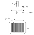
- the wire saw device 24 of the present invention includes a wire supply reel 1 extending from a wire 25 and a wire 25 extending from the wire supply reel 1 that can pass over the surface.
- the long roller 2 a plurality of wire guides 26 around which the wire 25 is spirally wound, the wire take-up reel 18 for winding the wire 25, and the wire supply reel 1 and the wire guide 26 are arranged and set.
- a tension arm 19 that is controlled to operate within a control angle ⁇ A (°) and applies tension to the wire 25.
- the wire 25 can pass on the long roller 2, moving in the axial direction of this long roller 2.
- the long roller 2 a plurality of wire guides 26 around which the wire 25 is spirally wound, the wire take-up reel 18 for winding the wire 25, and the wire supply reel 1 and the wire guide 26 are arranged and set
- the wire guide 26 may be composed of, for example, a main wire guide 10 and a slave wire guide 11.
- the wire 25 extended from the wire supply reel 1 passes through the long roller 2, the traverser 3, the pulley 4, the tension arm pulley 5, the tension sensor pulley 6, the pulley 7, the pulley 8, and the pulley 9, and the main wire guide 10 and the slave.
- the wire guide 11 is wound in parallel at a predetermined pitch to form a wire row 27.
- the work 23 is cut by moving the work 23 down to the wire row 27.
- the wire 25 exiting the slave wire guide 11 is wound around the wire take-up reel 18 through the pulley 12, the pulley 13, the tension sensor pulley 14, the tension arm pulley 15, the pulley 16, and the traverser 17.
- the traverser 3 can be used only when the traveling direction of the wire 25 is reversed and the wire supply reel 1 winds the wire.
- the position of the tension arm pulley 5 with respect to the tension detected by the tension sensor 20 is within the range of the set arbitrary control angle ⁇ A (°) with respect to the tension arm 19.
- the tension from the wire supply reel 1 to the main wire guide 10 can be controlled.
- the position of the tension arm pulley 15 moves within the arbitrary control range around the tension arm 22 with respect to the tension detected by the tension sensor 21. Can be controlled.
- control angle ⁇ A (°) of the tension arm 19 can be set within a range of ⁇ 1.5 °, for example.
- the surface roughness Rmax of the long roller 2 is 21 ⁇ m or less. Further, the smaller the surface roughness Rmax of the long roller 2, the easier the wire 25 moves on the long roller 2 in the axial direction of the long roller 2 and the deflection of the tension arm 19 becomes more stable. It will be good. In such a case, since the surface roughness Rmax of the long roller 2 is sufficiently small, the wire 25 extended from the wire supply reel 1 moves smoothly on the long roller 2 in the axial direction. It is possible to prevent the tension arm 19 from swinging out of the control range. Thereby, disconnection of the wire 25 can be reduced. Moreover, the minimum of the surface roughness Rmax of the long roller 2 is not specifically limited, For example, it can be 0 micrometer or more.
- the long roller 2 is made of urethane having a Shore hardness of A80 to 96. If it is in such a hardness range, the wire 25 can move smoothly, the shape change and the shape deterioration of the long roller 2 can be reduced, and the service life can be improved. Specifically, when the Shore hardness is A80 or more, deformation of the long roller 2 can be prevented and the number of times of use can be improved, and when the Shore hardness is A96 or less, processing to reduce the surface roughness (polishing) ) Can be performed efficiently.
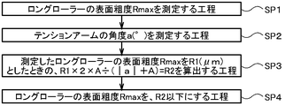
- a step of measuring the surface roughness Rmax of the long roller 2 is performed (SP1 in FIG. 2).
- a urethane roller having a Shore hardness of A80 to 96 is preferably used. If a material having such a hardness range is used, the wire 25 can easily move smoothly, the shape change and the shape deterioration of the long roller 2 can be reduced, and the service life can be improved. Specifically, when the Shore hardness is A80 or more, deformation of the long roller 2 can be prevented and the number of times of use can be improved, and when the Shore hardness is A96 or less, processing to reduce the surface roughness (polishing) ) Can be performed efficiently.
- the wire 25 is extended from the wire supply reel 1 and taken up by the wire take-up reel 18.
- the angle of the tension arm 19 is outside the set control angle ⁇ A (°).
- the step of measuring the angle a (°) of the tension arm 19 when the arm is swung is performed (SP2 in FIG. 2).
- a step of setting the surface roughness Rmax of the long roller 2 to be equal to or less than the calculated numerical value R2 is performed (SP4 in FIG. 2).
- the surface of the long roller 2 can be polished.
- the surface roughness Rmax of the long roller not more than the calculated numerical value R2 by polishing the surface of the long roller with a polishing film of # 800 to 3000.
- the average particle sizes of # 800 and # 3000 are 20 ⁇ m and 5 ⁇ m, respectively.
- the surface roughness Rmax of the long roller 2 can be more reliably set to R2 or less.
- it can prevent that a polishing film clogs and can grind
- polishing agent used for a polishing film silicon carbide, aluminum oxide, cerium oxide, etc. are mentioned.
- the polishing film can be polished by, for example, pressing the polishing film against the rotating long roller 2 using the polishing film as described above, but the polishing method is not limited thereto.
- this polishing can be performed multiple times on the same long roller. For example, when the surface roughness Rmax of the long roller 2 deteriorates as the wire saw device 24 is operated, the surface of the long roller 2 can be polished again, and the surface roughness Rmax can be set to R2 or less.
- a wire saw apparatus having a long roller having a surface roughness Rmax of R2 or less is manufactured.
- the wire extended from the wire supply reel is smoothly moved in the axial direction on the long roller, and the tension arm is prevented from swinging greatly outside the control range.
- a wire saw device can be manufactured. Thereby, the disconnection of the wire can be reduced.
- a wire saw device as shown in FIG. 1 (a) was manufactured.
- a urethane long roller 2 having a Shore hardness A91 was prepared.
- R1 ( ⁇ m) 34 ⁇ m.
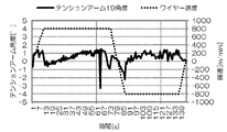
- the angle a (°) when the angle of the tension arm 19 suddenly swings outside the control range is ⁇ 3.2 °, and the surface roughness Rmax (R1) of the long roller 2 is 34 ⁇ m. there were.
- the wire saw device 24 was manufactured using the long roller 2 having a surface roughness Rmax of 21 ⁇ m. Then, the movement of the tension arm 19 when the wire 25 was extended at a linear speed of 800 m / min was measured and is shown in FIG. As a result, in FIG. 4, the sudden swing of the tension arm 19 seen in FIG. 3 outside the control range is not observed.
- the wire 25 is pulled from the wire supply reel 1.
- the angle when the tension arm 19 on the wire supply reel 1 side suddenly swings out of the control range is a (°)
- the surface roughness Rmax of the long roller 2 is R1.
- + A) is used, the tension arm 19 suddenly swings greatly outside the control range. It was possible to manufacture the wire saw device 24 of the present invention that can prevent the above.
- Example 1 (Comparative Example 1) Unlike Example 1, the surface roughness Rmax of the long roller was not particularly considered, and a long roller and each component were prepared to manufacture a wire saw device. For reference, the surface roughness Rmax of the long roller at this time was measured and found to be 34 ⁇ m. That is, it was the same as the wire saw device prepared first in Example 1.
- the same result as in FIG. 3 was obtained. That is, in the wire saw device manufactured in Comparative Example 1, the phenomenon that the angle of the tension arm suddenly swung out of the control range occurred, and the device showed signs of disconnection.
- Example 2-4 Comparative Examples 2 and 3
- a long roller having a surface roughness Rmax of 34 ⁇ m was prepared.
- This long roller was divided into 5 in the axial direction (the width in the axial direction was divided into 5 regions) and polished with polishing films having different numbers of # 600, 800, 2000, 3000, and 4000, respectively.
- the average abrasive grain sizes used in # 600, 800, 2000, 3000, and 4000 polishing films are 28, 20, 8, 5, and 3 ⁇ m, respectively.
- the surface roughness Rmax after polishing is 22 ⁇ m or less (more preferably 21 ⁇ m or less) in order to prevent the phenomenon that the angle of the tension arm suddenly fluctuates outside the control range. It is considered an eye.
- the result of measuring the surface roughness Rmax in the axial direction of the long roller before and after polishing is shown in FIG. As a result, as shown in FIG. 5, in # 600, the surface roughness Rmax deteriorated to 35 ⁇ m (Comparative Example 2). In # 4000, the polishing film was clogged and slid and could not be polished effectively, and the polishing was rounded up, so the surface roughness Rmax was 27 ⁇ m (Comparative Example 3). On the other hand, in # 800 to # 3000, the surface roughness Rmax is 22, 19, and 17 ⁇ m, respectively, all of which are 22 ⁇ m or less, and for # 2000 and # 3000, 21 ⁇ m or less can be achieved. Polishing was possible (Example 2-4).
- the present invention is not limited to the above embodiment.
- the above-described embodiment is an exemplification, and the present invention has any configuration that has substantially the same configuration as the technical idea described in the claims of the present invention and that exhibits the same effects. Are included in the technical scope.
Landscapes
- Engineering & Computer Science (AREA)
- Mechanical Engineering (AREA)
- Finish Polishing, Edge Sharpening, And Grinding By Specific Grinding Devices (AREA)
- Mechanical Treatment Of Semiconductor (AREA)
- Processing Of Stones Or Stones Resemblance Materials (AREA)
Abstract
Description
前記ロングローラーの表面粗度Rmaxを測定する工程と、
前記ワイヤ供給リールから前記ワイヤを延出しているときに、前記テンションアームの角度が、前記設定された制御角度の範囲外へ振れたときの、前記テンションアームの角度a(°)を測定する工程と、
前記測定した前記ロングローラーの表面粗度RmaxをR1(μm)としたときの、R1×2×A÷(|a|+A)=R2を算出する工程と、
前記ロングローラーの表面粗度Rmaxを、前記算出した数値R2以下にする工程とを有することを特徴とするワイヤソー装置の製造方法を提供する。
なお、ここでいう表面粗度Rmaxとは、JIS B0601に準じて測定される断面曲線の最大断面高さのことである。
前記ロングローラーの表面を#800~3000の研磨フィルムで研磨することで、前記ロングローラーの表面粗度Rmaxを前記算出した数値R2以下にすることが好ましい。
前記ロングローラーの表面粗度Rmaxが21μm以下のものであることを特徴とするワイヤソー装置を提供する。
上述したように、ワイヤ供給リールから延出されたワイヤがロングローラー上を軸方向に動きながら通過するワイヤソーでは、ロングローラーの軸方向に滑らかに移動しなかったワイヤが、突発的に本来の位置に戻る場合があり、この時、ワイヤ供給リール側のテンションアームが制御範囲外に大きく振れてしまい、ワイヤが断線するという問題があった。
実施例1とは異なり、ロングローラーの表面粗度Rmaxについては特に考慮せずに、ロングローラー及び各部品を用意し、ワイヤソー装置を製造した。なお、参考に、このときのロングローラーの表面粗度Rmaxを測定したところ、34μmであった。すなわち、実施例1で最初に用意したワイヤソー装置と同様のものであった。
実施例1で準備したロングローラーとは異なるが、表面粗度Rmaxが34μmのロングローラーを用意した。このロングローラーを、軸方向に5分割して(軸方向の幅を5つの領域に分けて)、各々、#600、800、2000、3000、4000の番手が異なる研磨フィルムでそれぞれ研磨した。#600、800、2000、3000、4000の研磨フィルムで使用されている平均砥粒径は、それぞれ28、20、8、5、3μmである。なお、実施例1における結果を考慮すると、テンションアームの角度が突発的に制御範囲外に大きく振れる現象を防ぐには、研磨後の表面粗度Rmaxが22μm以下(より好ましくは21μm以下)が狙い目と考えられる。
Claims (5)
- ワイヤを延出するワイヤ供給リールと、該ワイヤ供給リールから延出した前記ワイヤが表面上を通過可能なロングローラーと、前記ワイヤが周囲に螺旋状に巻き付けられる複数のワイヤガイドと、前記ワイヤを巻き取るワイヤ巻き取りリールと、前記ワイヤ供給リールと前記ワイヤガイドの間に配置され、設定された制御角度±A(°)内で動作するように制御され、前記ワイヤに張力を与えるテンションアームとを有し、前記ワイヤがロングローラー上を、該ロングローラーの軸方向に移動しながら通過可能であるワイヤソー装置の製造方法であって、
前記ロングローラーの表面粗度Rmaxを測定する工程と、
前記ワイヤ供給リールから前記ワイヤを延出しているときに、前記テンションアームの角度が、前記設定された制御角度の範囲外へ振れたときの、前記テンションアームの角度a(°)を測定する工程と、
前記測定した前記ロングローラーの表面粗度RmaxをR1(μm)としたときの、R1×2×A÷(|a|+A)=R2を算出する工程と、
前記ロングローラーの表面粗度Rmaxを、前記算出した数値R2以下にする工程とを有することを特徴とするワイヤソー装置の製造方法。 - 前記ロングローラーとして、ショア硬度A80~96からなるウレタン製のものを使用することを特徴とする請求項1に記載のワイヤソー装置の製造方法。
- 前記ロングローラーの表面粗度Rmaxを、前記算出した数値R2以下にする工程において、
前記ロングローラーの表面を#800~3000の研磨フィルムで研磨することで、前記ロングローラーの表面粗度Rmaxを前記算出した数値R2以下にすることを特徴とする請求項1又は請求項2に記載のワイヤソー装置の製造方法。 - ワイヤを延出するワイヤ供給リールと、該ワイヤ供給リールから延出した前記ワイヤが表面上を通過可能なロングローラーと、前記ワイヤが周囲に螺旋状に巻き付けられる複数のワイヤガイドと、前記ワイヤを巻き取るワイヤ巻き取りリールと、前記ワイヤ供給リールと前記ワイヤガイドの間に配置され、設定された制御角度±A(°)内で動作するように制御され、前記ワイヤに張力を与えるテンションアームとを有し、前記ワイヤがロングローラー上を、該ロングローラーの軸方向に移動しながら通過可能であるワイヤソー装置であって、
前記ロングローラーの表面粗度Rmaxが21μm以下のものであることを特徴とするワイヤソー装置。 - 前記ロングローラーが、ショア硬度A80~96からなるウレタン製のものであることを特徴とする請求項4に記載のワイヤソー装置。
Priority Applications (5)
| Application Number | Priority Date | Filing Date | Title |
|---|---|---|---|
| CN201780018553.1A CN108778623B (zh) | 2016-04-21 | 2017-02-24 | 线锯装置的制造方法及线锯装置 |
| US16/086,554 US11806827B2 (en) | 2016-04-21 | 2017-02-24 | Method for manufacturing wire saw apparatus and wire saw apparatus |
| DE112017001555.3T DE112017001555T5 (de) | 2016-04-21 | 2017-02-24 | Verfahren zum Herstellen einer Drahtsägevorrichtung und Drahtsägevorrichtung |
| SG11201808252VA SG11201808252VA (en) | 2016-04-21 | 2017-02-24 | Method for manufacturing wire saw apparatus and wire saw apparatus |
| KR1020187029338A KR102644660B1 (ko) | 2016-04-21 | 2017-02-24 | 와이어소 장치의 제조방법 및 와이어소 장치 |
Applications Claiming Priority (2)
| Application Number | Priority Date | Filing Date | Title |
|---|---|---|---|
| JP2016-085208 | 2016-04-21 | ||
| JP2016085208A JP6589735B2 (ja) | 2016-04-21 | 2016-04-21 | ワイヤソー装置の製造方法 |
Publications (1)
| Publication Number | Publication Date |
|---|---|
| WO2017183295A1 true WO2017183295A1 (ja) | 2017-10-26 |
Family
ID=60115941
Family Applications (1)
| Application Number | Title | Priority Date | Filing Date |
|---|---|---|---|
| PCT/JP2017/006980 Ceased WO2017183295A1 (ja) | 2016-04-21 | 2017-02-24 | ワイヤソー装置の製造方法及びワイヤソー装置 |
Country Status (8)
| Country | Link |
|---|---|
| US (1) | US11806827B2 (ja) |
| JP (1) | JP6589735B2 (ja) |
| KR (1) | KR102644660B1 (ja) |
| CN (1) | CN108778623B (ja) |
| DE (1) | DE112017001555T5 (ja) |
| SG (1) | SG11201808252VA (ja) |
| TW (1) | TWI715735B (ja) |
| WO (1) | WO2017183295A1 (ja) |
Families Citing this family (1)
| Publication number | Priority date | Publication date | Assignee | Title |
|---|---|---|---|---|
| CN110253775A (zh) * | 2019-07-26 | 2019-09-20 | 内蒙古中环光伏材料有限公司 | 一种切片机张力臂测控装置及切片工艺 |
Citations (3)
| Publication number | Priority date | Publication date | Assignee | Title |
|---|---|---|---|---|
| JPH02124253A (ja) * | 1988-10-28 | 1990-05-11 | Toray Ind Inc | ゴムロールのロール表面研磨方法 |
| JP2000061801A (ja) * | 1998-08-18 | 2000-02-29 | Hitachi Ltd | 切断方法および装置ならびに半導体装置の製造方法 |
| CN201645272U (zh) * | 2010-03-25 | 2010-11-24 | 陕西汉江机床有限公司 | 数控导丝辊磨床 |
Family Cites Families (13)
| Publication number | Priority date | Publication date | Assignee | Title |
|---|---|---|---|---|
| US4369934A (en) * | 1981-02-03 | 1983-01-25 | Spies Henry J | Helical filament winding apparatus |
| JPH11156694A (ja) | 1997-12-01 | 1999-06-15 | Hitachi Ltd | ワイヤーソー切断方法および装置 |
| TW383249B (en) * | 1998-09-01 | 2000-03-01 | Sumitomo Spec Metals | Cutting method for rare earth alloy by annular saw and manufacturing for rare earth alloy board |
| JP2000308925A (ja) * | 1999-04-28 | 2000-11-07 | Kyocera Corp | ワイヤ案内部材 |
| MY126994A (en) * | 1999-12-14 | 2006-11-30 | Hitachi Metals Ltd | Method and apparatus for cutting a rare earth alloy |
| JP2001246545A (ja) * | 1999-12-14 | 2001-09-11 | Sumitomo Special Metals Co Ltd | 希土類合金の切断方法および切断装置 |
| JP4411062B2 (ja) * | 2003-12-25 | 2010-02-10 | 株式会社アライドマテリアル | 超砥粒ワイヤソー巻き付け構造、超砥粒ワイヤソー切断装置および超砥粒ワイヤソーの巻き付け方法 |
| EP2075106B1 (en) * | 2006-10-20 | 2013-05-01 | Mitsubishi Electric Corporation | Slurry for silicon ingot cutting and method of cutting silicon ingot therewith |
| DE102007016334B4 (de) * | 2007-04-04 | 2011-04-21 | Siemens Ag | Drahtsäge und Verfahren zur Herstellung einer Drahtsäge |
| JP5003294B2 (ja) * | 2007-06-08 | 2012-08-15 | 信越半導体株式会社 | 切断方法 |
| JP4998241B2 (ja) * | 2007-12-11 | 2012-08-15 | 信越半導体株式会社 | ワイヤソーによるワークの切断方法およびワイヤソー |
| JP5155428B2 (ja) * | 2011-07-15 | 2013-03-06 | コマツNtc株式会社 | ワイヤソー |
| EP3081517B1 (de) * | 2015-04-17 | 2017-10-25 | Schleuniger Holding AG | Vorrichtung zum führen und fördern von draht- oder strangförmigen produkten |
-
2016
- 2016-04-21 JP JP2016085208A patent/JP6589735B2/ja active Active
-
2017
- 2017-02-24 DE DE112017001555.3T patent/DE112017001555T5/de active Pending
- 2017-02-24 WO PCT/JP2017/006980 patent/WO2017183295A1/ja not_active Ceased
- 2017-02-24 CN CN201780018553.1A patent/CN108778623B/zh active Active
- 2017-02-24 SG SG11201808252VA patent/SG11201808252VA/en unknown
- 2017-02-24 US US16/086,554 patent/US11806827B2/en active Active
- 2017-02-24 KR KR1020187029338A patent/KR102644660B1/ko active Active
- 2017-03-01 TW TW106106620A patent/TWI715735B/zh active
Patent Citations (3)
| Publication number | Priority date | Publication date | Assignee | Title |
|---|---|---|---|---|
| JPH02124253A (ja) * | 1988-10-28 | 1990-05-11 | Toray Ind Inc | ゴムロールのロール表面研磨方法 |
| JP2000061801A (ja) * | 1998-08-18 | 2000-02-29 | Hitachi Ltd | 切断方法および装置ならびに半導体装置の製造方法 |
| CN201645272U (zh) * | 2010-03-25 | 2010-11-24 | 陕西汉江机床有限公司 | 数控导丝辊磨床 |
Also Published As
| Publication number | Publication date |
|---|---|
| SG11201808252VA (en) | 2018-10-30 |
| TW201738022A (zh) | 2017-11-01 |
| CN108778623A (zh) | 2018-11-09 |
| KR102644660B1 (ko) | 2024-03-07 |
| JP6589735B2 (ja) | 2019-10-16 |
| KR20180134891A (ko) | 2018-12-19 |
| JP2017193021A (ja) | 2017-10-26 |
| DE112017001555T5 (de) | 2018-12-13 |
| US11806827B2 (en) | 2023-11-07 |
| TWI715735B (zh) | 2021-01-11 |
| US20190105750A1 (en) | 2019-04-11 |
| CN108778623B (zh) | 2020-07-03 |
Similar Documents
| Publication | Publication Date | Title |
|---|---|---|
| KR101676952B1 (ko) | 소잉 와이어를 이용하여 작업물로부터 웨이퍼들을 슬라이싱하기 위한 방법 | |
| CN106030764B (zh) | 硅晶片的制造方法和硅晶片 | |
| KR102545544B1 (ko) | 워크의 절단방법 및 와이어소 | |
| JP6589744B2 (ja) | ワークの切断方法 | |
| TW202015841A (zh) | 用於從工件同時切割多個盤的方法和裝置 | |
| US20140261368A1 (en) | Bandsaw cutting appartus and method for cutting ingot | |
| JP2018520909A (ja) | ワークピースを切断するための方法 | |
| WO2015075869A1 (ja) | ワークの切断方法 | |
| JP5958430B2 (ja) | ワークの切断方法及びワイヤソー | |
| WO2015053148A1 (ja) | 固定砥粒ワイヤソー装置及びこれを用いたウエハの製造方法 | |
| JP6080753B2 (ja) | ワイヤソーの運転再開方法 | |
| CN113272101B (zh) | 工件的切断方法及工件的切断装置 | |
| JP6589735B2 (ja) | ワイヤソー装置の製造方法 | |
| WO2017119030A1 (ja) | インゴットの切断方法 | |
| WO2020230423A1 (ja) | ワークの切断方法及びワイヤソー | |
| JP6493243B2 (ja) | ウェーハの製造方法 | |
| JP6277924B2 (ja) | インゴットの切断方法 | |
| JP5861062B2 (ja) | ワイヤーソーとワイヤーソーを用いたシリコン製造方法 | |
| JP6835213B2 (ja) | ワークの切断方法及び接合部材 | |
| JP4325655B2 (ja) | 化合物半導体基板の製造方法 | |
| JP5945967B2 (ja) | ワークの切断方法及びワイヤソー | |
| JP5991267B2 (ja) | ワークの切断方法および切断装置 | |
| JP2013233606A (ja) | ワイヤソー装置及び切断加工方法 | |
| KR20130074711A (ko) | 잉곳 절단 장치 및 잉곳 절단 방법 | |
| JP2013052463A (ja) | ワイヤソー装置およびワーク切断方法、ウエハの製造方法 |
Legal Events
| Date | Code | Title | Description |
|---|---|---|---|
| WWE | Wipo information: entry into national phase |
Ref document number: 11201808252V Country of ref document: SG |
|
| ENP | Entry into the national phase |
Ref document number: 20187029338 Country of ref document: KR Kind code of ref document: A |
|
| 121 | Ep: the epo has been informed by wipo that ep was designated in this application |
Ref document number: 17785640 Country of ref document: EP Kind code of ref document: A1 |
|
| 122 | Ep: pct application non-entry in european phase |
Ref document number: 17785640 Country of ref document: EP Kind code of ref document: A1 |