WO2017179323A1 - 燃料噴射弁 - Google Patents
燃料噴射弁 Download PDFInfo
- Publication number
- WO2017179323A1 WO2017179323A1 PCT/JP2017/007585 JP2017007585W WO2017179323A1 WO 2017179323 A1 WO2017179323 A1 WO 2017179323A1 JP 2017007585 W JP2017007585 W JP 2017007585W WO 2017179323 A1 WO2017179323 A1 WO 2017179323A1
- Authority
- WO
- WIPO (PCT)
- Prior art keywords
- valve body
- downstream
- seating
- inlet
- valve
- Prior art date
- Legal status (The legal status is an assumption and is not a legal conclusion. Google has not performed a legal analysis and makes no representation as to the accuracy of the status listed.)
- Ceased
Links
Images


Classifications
-
- F—MECHANICAL ENGINEERING; LIGHTING; HEATING; WEAPONS; BLASTING
- F02—COMBUSTION ENGINES; HOT-GAS OR COMBUSTION-PRODUCT ENGINE PLANTS
- F02M—SUPPLYING COMBUSTION ENGINES IN GENERAL WITH COMBUSTIBLE MIXTURES OR CONSTITUENTS THEREOF
- F02M61/00—Fuel-injectors not provided for in groups F02M39/00 - F02M57/00 or F02M67/00
- F02M61/16—Details not provided for in, or of interest apart from, the apparatus of groups F02M61/02 - F02M61/14
- F02M61/18—Injection nozzles, e.g. having valve seats; Details of valve member seated ends, not otherwise provided for
- F02M61/1873—Valve seats or member ends having circumferential grooves or ridges, e.g. toroidal
-
- F—MECHANICAL ENGINEERING; LIGHTING; HEATING; WEAPONS; BLASTING
- F02—COMBUSTION ENGINES; HOT-GAS OR COMBUSTION-PRODUCT ENGINE PLANTS
- F02M—SUPPLYING COMBUSTION ENGINES IN GENERAL WITH COMBUSTIBLE MIXTURES OR CONSTITUENTS THEREOF
- F02M61/00—Fuel-injectors not provided for in groups F02M39/00 - F02M57/00 or F02M67/00
- F02M61/16—Details not provided for in, or of interest apart from, the apparatus of groups F02M61/02 - F02M61/14
- F02M61/18—Injection nozzles, e.g. having valve seats; Details of valve member seated ends, not otherwise provided for
Definitions
- the present disclosure relates to a fuel injection valve that injects fuel from an injection hole.
- a conventional general fuel injection valve is configured by accommodating a valve body in a body.
- the body is formed with a nozzle hole for injecting fuel and a supply channel for supplying fuel to the nozzle hole.
- a part of the channel wall surface forming the supply channel in the body functions as a seating surface that extends in an annular shape around the central axis of the valve body. The supply flow path is opened and closed when the valve element is seated and separated on the seating surface, and the fuel injection from the injection hole and the injection stop are switched.
- the supply flow path includes an annular flow path formed between the inner peripheral surface of the body and the outer peripheral surface of the valve body, and fuel that is located downstream of the valve body and flows through the annular flow path on the central axis.
- the annular distribution type that distributes fuel from the sac chamber to the nozzle holes provided in the sac chamber
- the annular distribution type that distributes fuel from the annular channel to the nozzle holes provided in the annular channel (patented) Development of reference 1) is underway.
- the sac distribution type even if the valve body is seated to stop fuel injection, immediately after the seating, most of the fuel remaining in the sac chamber leaks from the nozzle hole, and the fuel is discharged from the nozzle hole at a low speed. Will be.
- the annular distribution type it is unnecessary to provide a space for forming the nozzle hole in the sac chamber, so that the capacity of the sac chamber can be reduced, and the amount of leakage can be reduced.
- the nozzle hole is located on the upstream side of the sac chamber, the fuel remaining in the sack chamber is hardly leaked from the nozzle hole.
- the inlet of the nozzle hole is arranged in a conical surface portion on the same plane as the seating surface of the body wall surface. For this reason, fuel that has passed through a narrow gap between the seating surface and the valve body and has a high flow velocity immediately changes direction and contracts in the vicinity of the nozzle hole inlet immediately after flowing along the conical surface of the body. It flows into the nozzle hole. Therefore, compared with the case of the sac distribution type in which fuel flows from the sac chamber to the nozzle hole, in the case of the annular distribution type, the flow resistance of the fuel when flowing into the nozzle hole increases, and the pressure loss may increase. .
- the upstream portion of the inlet of the nozzle hole is shaped to be expanded upstream, thereby suppressing a sudden change in the flow direction when the fuel flows into the nozzle hole. To reduce pressure loss.
- An object of the present disclosure is to provide a fuel injection valve that promotes reduction in fuel pressure loss while suppressing fuel from being discharged from an injection hole at a low speed immediately after a valve body is seated. .
- a fuel injection valve includes: a body in which a fuel injection hole and a supply channel for supplying fuel to the nozzle hole are formed; and a valve body that opens and closes the supply channel.
- a body-side depression having a shape that allows the body to be recessed, and the inlet of the nozzle hole is located on the seating downstream surface, and the body-side depression is upstream of the inlet that is the portion of the inlet closest to the seating surface.
- the downstream end of the inlet that is the portion of the inlet that is farthest from the seating surface In circumference
- the inlet of the injection hole is located on the seating downstream surface of the shape facing the outer peripheral surface of the valve body and extending annularly around the central axis. That is, it means that the fuel injection valve according to the above disclosure is the above-described annular distribution type.
- a body-side depression portion is formed on the seating downstream surface so that the body is depressed toward the side away from the central axis.
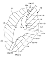
- the body-side depression has an annular shape around the central axis in a range including the inlet upstream end and the inlet downstream end. Therefore, among the fuel that flows into the inlet along the seating downstream surface, for example, when the inlet shown in FIG. 3 is viewed from the front in the center line direction, the fuel that flows from above the central axis reaches the inlet. Is enlarged by the body-side depression.
- the flow path leading to the inflow port is enlarged by the body-side depression. Therefore, for example, in addition to the fuel flowing in from the upper side of the inflow port as illustrated by the arrow F1 in FIG. 3, the fuel flowing in from the oblique upper side as illustrated by the arrow F2 or the lateral direction illustrated by the arrow F3. Even for the fuel flowing in from the direction, the pressure loss is reduced by expanding the flow path. Therefore, according to the fuel injection valve according to the above disclosure, the pressure loss of the fuel flowing into the nozzle hole is reduced as compared with the fuel injection valve described in Patent Document 1 in which the upstream portion of the inflow port is only expanded upstream. Can be reduced.
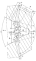
- FIG. 1 is a cross-sectional view schematically illustrating a fuel injection valve according to a first embodiment of the present disclosure.
- FIG. 2 is an enlarged view of the nozzle hole portion of FIG.
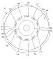
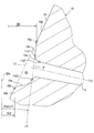
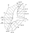
- FIG. 3 is a cross-sectional view showing a single body state of the body according to the first embodiment. 4 is a view taken in the direction of arrow IV in FIG.
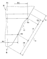
- FIG. 5 is a cross-sectional view showing a single body state according to the first embodiment, and is a diagram for explaining a tangent to a hollow portion and an inflow angle.
- FIG. 1 is a cross-sectional view schematically illustrating a fuel injection valve according to a first embodiment of the present disclosure.
- FIG. 2 is an enlarged view of the nozzle hole portion of FIG.
- FIG. 5 is a cross-sectional view showing
- FIG. 6 is a front view showing a single body state of the valve body according to the first embodiment
- FIG. 7 is a view taken along arrow VII in FIG.
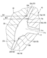
- FIG. 8 is a cross-sectional view showing the positional relationship between the body-side depression and the valve body-side depression in the first embodiment
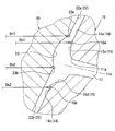
- FIG. 9 is a cross-sectional view showing the positional relationship between the body-side depression and the valve body-side depression in the fuel injection valve according to the second embodiment of the present disclosure
- FIG. 10 is a cross-sectional view showing the positional relationship between the body-side depression and the valve body-side depression in the fuel injection valve according to the third embodiment of the present disclosure
- FIG. 11 is a cross-sectional view showing the positional relationship between the body-side depression and the valve body-side depression in the fuel injection valve according to the fourth embodiment of the present disclosure.
- the fuel injection valve according to the present embodiment is applied to an internal combustion engine mounted on a vehicle, and injects fuel used for combustion of the internal combustion engine.
- the internal combustion engine is a diesel engine that injects high-pressure fuel into a plurality of cylinders and performs compression self-ignition combustion.
- the fuel injection system shown in FIG. 1 has a plurality of fuel injection valves 5, a common rail 6 that accumulates fuel discharged from a high-pressure pump (not shown) and distributes the fuel to each of the fuel injection valves 5, and the operation of the fuel injection valves 5. And a control device 7 for controlling.
- the fuel injection valve 5 includes a body 10, a valve body 20, an actuator 30, a control valve 40, an elastic member 50, and the like.
- the valve body 20, the actuator 30 and the control valve 40 are accommodated in the body 10.
- the body 10 is formed with a plurality of injection holes 11 and a supply flow path 12 for supplying fuel to the injection holes 11.
- a part of the supply flow path 12 functions as a valve body accommodating chamber 12a for accommodating the valve body 20.
- the valve body 20 has a cylindrical shape extending in the vertical direction in FIG. 1 and is disposed so as to be reciprocally movable in the valve body accommodating chamber 12a.
- the direction in which the central axis 20c of the valve body 20 extends that is, the direction of the center line of the cylindrical shape coincides with the reciprocating direction of the valve body 20.
- the supply flow path 12 in the valve body housing chamber 12 a is formed between the flow path wall surface 10 a forming the supply flow path 12 in the body 10, that is, the inner peripheral surface of the body 10 and the outer peripheral surface 20 a of the valve body 20. Cylindrical shape.
- a part of the channel wall surface 10a functions as a seating surface 13 on which the seat surface 21 of the valve body 20 is seated.
- the seating surface 13 has a shape extending annularly around the central axis 20c, and is located in the valve body accommodating chamber 12a.
- the seat surface 21 has a shape that extends annularly around the central axis 20c.
- the seating surface 13 and the seat surface 21 are inclined with respect to the central axis 20c, and have a conical tapered shape whose diameter gradually decreases toward the downstream side of the fuel flow.
- a back pressure chamber 10b into which a part of high-pressure fuel flowing through the supply flow path 12 flows is provided on the opposite side of the seat surface 21 with respect to the valve body 20.
- the back pressure which is the pressure of the fuel that fills the back pressure chamber 10b, acts as a force that pushes the valve body 20 toward the valve closing side (back pressure closing force).
- the elastic force of the elastic member 50 acts on the valve body 20 as a force (elastic valve closing force) that presses the valve body 20 toward the valve closing side.
- the pressure of the fuel that fills the valve body storage chamber 12a is applied to the portion upstream of the seat surface 21 of the tip surface of the valve body 20 as a force (valve opening force) that presses the valve body 20 toward the valve opening side.
- the control valve 40 controls the communication state between the back pressure chamber 10b and the low pressure passage 12L. That is, when the control valve 40 is opened, the back pressure chamber 10b communicates with the low pressure passage 12L, and the high pressure fuel in the back pressure chamber 10b flows into the low pressure passage 12L and the back pressure decreases. When the back pressure is reduced, the valve body 20 is opened as the back pressure closing force is reduced. On the other hand, when the control valve 40 is operated to close, the communication between the back pressure chamber 10b and the low pressure passage 12L is blocked, and the high pressure fuel in the back pressure chamber 10b is stopped from flowing out to the low pressure passage 12L. As a result, the back pressure rises and the valve body 20 is closed.
- the opening / closing operation of the control valve 40 is controlled by the actuator 30.
- An electromagnetic coil or a piezo element is used for the actuator 30.
- a piezo element is used, and when the control device 7 controls the energization state so that electric power is supplied to the piezo element, the command piston 31 that is pressed by the piezo element pushes the control valve 40 to open the valve. Operate.
- FIG. 2 is a diagram for explaining the detailed shape of the nozzle hole 11 portion of the body 10 and the detailed shape of the distal end surface of the valve body 20.
- the body 10 is represented by a sectional view and the valve body 20 is represented by a front view. ing.
- the portion of the channel wall surface 10a that is connected to the downstream side of the seating surface 13 and that faces the outer peripheral surface 20a of the valve body 20 in the closed state is referred to as a seating downstream surface 14.
- the seating downstream surface 14 has a shape that extends annularly around the central axis 20c, and has a conical taper shape that gradually decreases in diameter toward the downstream side of the fuel flow.
- a part of the supply flow path 12 functions as a sac chamber 12b connected to the downstream side of the valve body storage chamber 12a.
- the top portion 20d of the valve body 20 in the closed state is located in the sack chamber 12b (see FIG. 2). However, in a state where the valve body 20 is at the maximum opening position, the top portion 20d of the valve body 20 is located on the upstream side of the sac chamber 12b.
- the supply flow path 12 in the valve body accommodating chamber 12a is cylindrical, and in particular, the longitudinal cross-sectional shape of the seating surface 13 and the seating downstream surface 14 is a tapered shape in which the annular diameter becomes smaller toward the downstream side.
- the supply flow path 12 in the sac chamber 12b has a columnar shape that communicates with a cylindrical end surface that is the downstream end of the valve body housing chamber 12a, and collects fuel that has flown in the valve body housing chamber 12a in an annular shape.
- the plurality of nozzle holes 11 are arranged at the same position in the direction in which the central axis 20c extends (the vertical direction in FIG. 3).
- the inlet 11a and the outlet 11b of the nozzle hole 11 are circular.
- the opening area of the inflow port 11a is larger than the opening area of the outflow port 11b.
- the peripheral edge of the inflow port 11a has a curved shape in which the opening area increases as it approaches the upstream side.
- the inflow port 11a is formed in the seating downstream surface 14, in other words, a portion of the flow channel wall surface 10a that is inclined with respect to the central axis 20c, and the outer peripheral surface of the valve body 20 in the flow channel wall surface 10a. It is formed in a portion facing 20a.
- the plurality of nozzle holes 11 are arranged at equal intervals around the central axis 20 c.
- the nozzle hole 11 has a shape extending linearly in a direction away from the central axis 20c.
- the direction in which the center line 11 c of the nozzle hole 11 extends is inclined with respect to a plane perpendicular to the center axis 20 c of the valve body 20.
- a value twice the angle formed by the center line 11c of the nozzle hole 11 and the center axis 20c of the valve body 20 is referred to as a nozzle hole cone angle ⁇ h.
- the seating downstream surface 14 is formed with a body-side depression 15 having a shape that allows the body 10 to be depressed toward the side away from the central axis 20c.
- the body-side depression 15 has a shape extending annularly around the central axis 20c.
- a portion of the seating downstream surface 14 upstream of the body-side depression 15 is referred to as a first seating downstream surface 14a, and a portion of the downstream side is referred to as a second seating downstream surface 14b.
- the first seating downstream surface 14a, the second seating downstream surface 14b, and the seating surface 13 are located on the same conical surface L1. That is, the tangential directions of the first seating downstream surface 14a, the second seating downstream surface 14b, and the seating surface 13 are the same.
- the body-side recessed portion 15 of the seating downstream surface 14 is recessed in a direction away from the central axis 20c with respect to the conical surface L1.
- the range where the body-side depression 15 is formed in the direction of the central axis 20 c includes the entire inlet 11 a of the injection hole 11. That is, the upstream end 15a of the body-side depression 15 that is the boundary line between the body-side depression 15 and the first seating downstream surface 14a is located upstream of the inflow port 11a. Moreover, the downstream end 15b of the body side dent part 15 which is a boundary line of the body side dent part 15 and the 2nd seating downstream surface 14b is located downstream from the inflow port 11a.
- the boundary line by the upstream end 15a and the boundary line by the downstream end 15b of the body-side depression 15 are circular with the central axis 20c as the center.
- the bottom surface of the body-side depression 15 is divided into a first bottom surface 15c and a second bottom surface 15d described below.
- the first bottom surface 15c is a surface in a range upstream of the downstream end (inlet downstream end 11a3) of the inflow port 11a (upper side in FIG. 5) in the direction of the central axis 20c.
- the second bottom surface 15d is a bottom surface in a range on the downstream side (lower side in FIG. 5) from the inlet downstream end 11a3 in the direction of the central axis 20c.
- the first bottom surface 15c has a conical surface shape, and has a shape extending linearly in a predetermined tangential direction in a longitudinal sectional view.
- This predetermined tangent line is a line where a plane including the center line 11c of the nozzle hole 11 and the center axis 20c of the valve body 20 intersects with a first bottom surface 15c connected to the inlet upstream end 11a1 of the bottom surface of the body-side depression 15. And is called the dent tangent L2.
- the angle formed by the center line 11c of the nozzle hole 11 and the dent tangent L2 is referred to as an inflow angle ⁇ .
- a value twice the angle formed by the dent tangent L2 of the first bottom surface 15c and the central axis 20c of the valve body 20 is referred to as a dent tangent angle ⁇ bin.
- the direction of the center line 11c and the depression tangent L2 is set so that the inflow angle ⁇ defined in this way is larger than 90 °. That is, the inflow angle ⁇ is an obtuse angle.
- the upstream end (inlet upstream end 11a1) of the inflow port 11a is continuous with the first bottom surface 15c so that the tangential direction is the same as that of the first bottom surface 15c.
- the terminal end 11a2 of the inflow port 11a is continuous with the inner wall surface so that the tangential direction is the same as the inner wall surface of the nozzle hole 11.
- the shape of the inflow port 11a from the inflow port upstream end 11a1 to the end point 11a2 is a shape curved in a direction that is convex toward the center line 11c side.
- the shape of the inflow port 11a from the inflow port upstream end 11a1 to the terminal end 11a2 may be a tapered shape that is a flat surface.
- the portion of the outer peripheral surface 20 a of the valve body 20 that is connected to the downstream side of the seat surface 21 is referred to as a seat downstream surface 22.
- the seat downstream surface 22 has a shape that extends annularly around the central axis 20c, and has a conical taper shape that gradually decreases in diameter toward the downstream side of the fuel flow.
- the seat downstream surface 22 is formed with a valve body side recess 23 having a shape that allows the valve body 20 to be recessed toward the side closer to the central axis 20c.
- the valve-body-side depression 23 has a shape that extends annularly around the central axis 20c.
- a portion upstream of the valve body side recess 23 is referred to as a first seat downstream surface 22 a and a downstream portion is referred to as a second seat downstream surface 22 b.
- the first sheet downstream surface 22a, the second sheet downstream surface 22b, and the sheet surface 21 are located on the same conical surface L3. That is, the tangential directions of the first sheet downstream surface 22a, the second sheet downstream surface 22b, and the sheet surface 21 are the same.
- the part of the valve body side depression 23 in the seat downstream surface 22 is recessed in a direction approaching the central axis 20c with respect to the conical surface L3.
- the upstream end 23a of the valve body-side depression 23 that is the boundary line between the valve-body depression 23 and the first seat downstream surface 22a is upstream of the upstream end 15a of the body-side depression 15.
- the downstream end 23b of the valve body side recess 23 that is the boundary line between the valve body side recess 23 and the second seat downstream surface 22b is more than the downstream end 15b of the body side recess 15. Is also located downstream.
- the fuel flow direction Fa the direction parallel to the first seating downstream surface 14a in the cross-sectional view taken along the plane including the central axis 20c as shown in FIG. 8 is referred to as the fuel flow direction Fa.
- the valve body 20 is closed, and the body-side depression 15 and the valve-side depression 23 are set in the following positional relationship. That is, the upstream end 23 a of the valve body side recess 23 is positioned upstream of the upstream end 15 a of the body side recess 15, and the downstream end 23 b of the valve body side recess 23 is from the downstream end 15 b of the body side recess 15. Is also located downstream.
- the boundary line formed by the upstream end 23a and the boundary line formed by the downstream end 23b of the valve body-side depression 23 are circular with the central axis 20c as the center.
- the range in which the valve body-side depression 23 is formed in the direction of the central axis 20c includes the entire body-side depression 15 with the valve body 20 closed.
- the diameter Db1 of the upstream end 15a of the body-side depression 15 is set to be equal to or smaller than the diameter Dn1 of the upstream end 23a of the valve-side depression 23 (Db1 ⁇ Dn1).
- the diameter Dn2 of the downstream end 23b of the valve body-side depression 23 is set to be equal to or smaller than the diameter Db2 of the downstream end 15b of the body-side depression 15 (Dn2 ⁇ Db2).
- the inlet 11a of the nozzle hole 11 is formed at the seating downstream surface 14 and is at a position facing the outer peripheral surface 20a of the valve body 20 at the valve closing position. That is, the inflow port 11a of the nozzle hole 11 is located in the annular flow path formed between the seating downstream surface 14 and the outer peripheral surface 20a, and is located upstream of the sac chamber 12b. Therefore, an annular distribution type fuel injection valve 5 in which fuel is distributed from the annular flow path to the plurality of injection holes 11 is provided. Accordingly, since it is unnecessary to provide a space for forming the nozzle hole 11 in the sac chamber 12b, the capacity of the sac chamber 12b can be reduced.
- a body-side depression 15 is formed on the seating downstream surface 14.
- the body-side depression 15 has a shape extending annularly around the central axis 20c in a range including the inlet upstream end 11a1 and the inlet downstream end 11a3. Therefore, the flow path of the fuel flowing into the inlet 11a from the direction shown by the arrow F1 in FIG. 3, that is, the fuel flowing in from the upper side of the central axis 20c when the inlet 11a is viewed in the direction of the center line 11c is the body side.
- the recess 15 enlarges the seating downstream surface 14 in a direction perpendicular to the seating downstream surface 14.
- the pressure loss with respect to the fuel flowing into the inflow port 11a from the direction indicated by the arrow F1, that is, from above is reduced.
- the fuel flow path is expanded in the direction perpendicular to the seating downstream surface 14 by the body-side depression 15. . Therefore, the pressure loss is also reduced for the fuel flowing into the inflow port 11a from the direction indicated by the arrow F2, that is, the direction intersecting the central axis 20c in the front view (obliquely upward).
- the flow path leading to the inflow port 11a is expanded by the body-side depression 15 and the pressure loss Is reduced.
- the pressure loss of the fuel flowing into the injection hole 11 is reduced as compared with the fuel injection valve described in Patent Document 1 in which the inflow port 11a is simply expanded upward. it can.
- the fuel can be prevented from leaking out of the nozzle hole 11 at a low speed immediately after the valve body 20 is seated, and the pressure loss of the fuel can be reduced. Can promote.
- the inflow port 11a has a shape that gradually increases the diameter of the injection hole 11 as it is upstream of the injection hole 11. Specifically, the inflow port 11a has a curved shape that gradually enlarges the opening area perpendicular to the center line 11c. Therefore, it is possible to suppress a rapid change in the flow direction when the fuel flows into the nozzle hole 11, and the pressure loss reduction is promoted.
- the inflow angle ⁇ which is an angle formed by the center line 11c of the nozzle hole 11 and the dent tangent L2, is an obtuse angle. Therefore, compared with the case where the inflow angle ⁇ is 90 degrees or less, it is possible to suppress a sudden change in the flow direction when the fuel flows into the nozzle hole 11, and the pressure loss reduction is promoted.
- valve body side hollow part 23 is formed in the downstream part of the seat surface 21 among the outer peripheral surfaces 20a of the valve body 20.
- the valve body side recess 23 has a shape that allows the valve body 20 to be recessed toward the side closer to the central axis 20c, and a shape that extends annularly around the central axis 20c. Therefore, the flow path to the inflow port 11 a is expanded in the direction perpendicular to the seating downstream surface 14 by the valve body-side recess portion 23 in addition to being expanded by the body-side recess portion 15. Therefore, the pressure loss can be further reduced.
- the valve body 20 is in a closed state, and the upstream end 23a of the valve body-side recess 23 is positioned upstream of the upstream end 15a of the body-side recess (see FIG. 8). Therefore, the flow path of the fuel flowing along the first seating downstream surface 14a is enlarged before reaching the first bottom surface 15c of the body-side depression 15. Therefore, as indicated by an arrow Fb in FIG. 8, the fuel that has flowed along the first seating downstream surface 14a flows so as to swell toward the outer surface 20a of the valve body 20 and then flows into the inlet 11a. To do. Therefore, when the fuel flows into the inflow port 11a while changing the direction, the radius of the inflow path of the fuel can be increased, and a sudden change in the flow direction can be suppressed. Therefore, the pressure loss can be further reduced.
- valve body 20 is in a closed state, and the downstream end 23b of the valve body-side depression 23 is located downstream of the inlet upstream end 11a1 (see FIG. 8). Therefore, the flow of the fuel flowing along the first bottom surface 15 c of the body-side depression 15 is expanded by the valve body-side depression 23 in addition to the body-side depression 15. Therefore, it is possible to promote that the fuel swells and flows into the inflow port 11a as indicated by the arrow Fb described above, and it is possible to promote suppression of a sudden change in the flow direction.
- the downstream end 23b of the valve body side recess 23 is located on the opposite side of the inlet upstream end 11a1 with respect to the inlet downstream end 11a3 (see FIG. 8). Therefore, as shown by an arrow F3 in FIG. 3, the flow of the fuel flowing from the circumferential direction to the inflow port 11a is expanded by the valve-side depression 23 in addition to the body-side depression 15. And since the upstream end 23a of the valve body side hollow part 23 is located on the opposite side of the inlet downstream end 11a3 with respect to the inlet upstream end 11a1, the whole inlet 11a is covered with the valve body side hollow part 23. Become. Therefore, it can further promote that the fuel swells and flows into the inflow port 11a as indicated by the arrow Fb described above, and the suppression of sudden change in the flow direction can be promoted.
- the downstream end 23 b of the valve body-side depression 23 is located on the opposite side of the upstream end 15 a of the body-side depression 15 with respect to the downstream end 15 b of the body-side depression 15. Therefore, the pressure loss reduction can be further promoted for the fuel flowing from the circumferential direction to the inlet 11a as indicated by the arrow F3 in FIG. Moreover, since the upstream end 23 a of the valve body side recess 23 is located on the opposite side of the downstream end 15 b with respect to the upstream end 15 a of the body side recess 15, the entire body side recess 15 is formed by the valve body side recess 23. Will be covered. Therefore, it can further promote that the fuel swells and flows into the inflow port 11a as indicated by the arrow Fb described above, and the suppression of sudden change in the flow direction can be promoted.
- the magnitude relationship between the diameter Dn2 of the downstream end 23b of the valve body side recess 23 and the diameter Db2 of the downstream end 15b of the body side recess 15 is such that Dn2 ⁇ Db2 when the valve body 20 is closed.
- the valve body 20 is in a closed state, and Dn2> Db2 is set.
- the magnitude relationship between the diameter Db1 of the upstream end 15a of the body side recess 15 and the diameter Dn1 of the upstream end 23a of the valve body side recess 23 is set to Db1 ⁇ Dn1 as in the first embodiment. .
- the valve body 20 in the fuel flow direction Fa parallel to the first seating downstream surface 14a, the valve body 20 is in a closed state, and the downstream end 23b of the valve body side recess 23 is It is located downstream of the downstream end 15b.
- the valve body 20 in the fuel flow direction Fa, the valve body 20 is in a closed state, and the downstream end 23 b of the valve body side recess 23 is the downstream end 15 b of the body side recess 15. It is located on the upstream side.
- the magnitude relationship between the diameter Db1 of the upstream end 15a of the body-side depression 15 and the diameter Dn1 of the upstream end 23a of the valve-side depression 23 is such that Db1 ⁇ Dn1 when the valve body 20 is closed.
- the valve body 20 is in a closed state, and Db1> Dn1 is set.
- the magnitude relationship between the diameter Dn2 of the downstream end 23b of the valve body-side depression 23 and the diameter Db2 of the downstream end 15b of the body-side depression 15 is set to Dn2 ⁇ Db2 as in the first embodiment. .
- valve body 20 In this embodiment shown in FIG. 11, the valve body 20 is in a closed state, and Db1> Dn1 and Dn2> Db2 are set.
- valve body 20 is in the closed state, and the downstream end 23b of the valve body side recess 23 is recessed on the body side in the same manner as in the second embodiment. It is located upstream of the downstream end 15b of the portion 15.
- the upstream end 23a of the valve body-side depression 23 is positioned upstream of the upstream end 15a of the body-side depression 15 in the same manner as in the first embodiment.
- the valve body 20 is in a closed state, and the upstream end 23a of the valve body-side depression 23 is located upstream of the upstream end 15a of the body-side depression 15.
- the upstream end 23 a of the valve body-side depression 23 may be located downstream of the upstream end 15 a of the body-side depression 15.
- it is desirable that the upstream end 23a of the valve body side recess 23 is located upstream of the inlet upstream end 11a1.
- valve body side recess 23 is provided in the valve body 20, but if the body 10 is provided with the body side recess 15, the valve body side recess 23 may be eliminated.
- Dn2 ⁇ Db2 is set in order to position the downstream end 23b of the valve body side depression 23 on the upstream side of the downstream end 15b of the body side depression 15.
- the downstream end 23b of the valve body side recess 23 may be positioned upstream of the downstream end 15b of the body side recess 15 while setting Dn2> Db2.
- the inflow port 11a has a curved shape in the longitudinal sectional view of FIG.
- the taper shape in which the inflow port 11a inclined linearly in the longitudinal cross-sectional view of FIG. 5 may be sufficient.
- the inflow port 11a shown in FIG. 5 has a shape that gradually increases the diameter of the injection hole 11 as it is on the upstream side of the injection hole 11, it may have a shape that does not increase the diameter.
- the inflow angle ⁇ is set to an obtuse angle as shown in FIG. 5, but the inflow angle ⁇ may be set to 90 degrees or may be set to an acute angle.
Landscapes
- Engineering & Computer Science (AREA)
- Chemical & Material Sciences (AREA)
- Combustion & Propulsion (AREA)
- Mechanical Engineering (AREA)
- General Engineering & Computer Science (AREA)
- Fuel-Injection Apparatus (AREA)
Priority Applications (1)
| Application Number | Priority Date | Filing Date | Title |
|---|---|---|---|
| DE112017002016.6T DE112017002016T5 (de) | 2016-04-15 | 2017-02-28 | Kraftstoffeinspritzventil |
Applications Claiming Priority (2)
| Application Number | Priority Date | Filing Date | Title |
|---|---|---|---|
| JP2016-081711 | 2016-04-15 | ||
| JP2016081711A JP6390659B2 (ja) | 2016-04-15 | 2016-04-15 | 燃料噴射弁 |
Publications (1)
| Publication Number | Publication Date |
|---|---|
| WO2017179323A1 true WO2017179323A1 (ja) | 2017-10-19 |
Family
ID=60041626
Family Applications (1)
| Application Number | Title | Priority Date | Filing Date |
|---|---|---|---|
| PCT/JP2017/007585 Ceased WO2017179323A1 (ja) | 2016-04-15 | 2017-02-28 | 燃料噴射弁 |
Country Status (3)
| Country | Link |
|---|---|
| JP (1) | JP6390659B2 (enExample) |
| DE (1) | DE112017002016T5 (enExample) |
| WO (1) | WO2017179323A1 (enExample) |
Cited By (1)
| Publication number | Priority date | Publication date | Assignee | Title |
|---|---|---|---|---|
| WO2019110167A1 (de) * | 2017-12-04 | 2019-06-13 | Robert Bosch Gmbh | Ventil zum zumessen eines fluids, insbesondere brennstoffeinspritzventil |
Families Citing this family (1)
| Publication number | Priority date | Publication date | Assignee | Title |
|---|---|---|---|---|
| JP7124351B2 (ja) | 2018-03-08 | 2022-08-24 | 株式会社デンソー | 燃料噴射弁および燃料噴射システム |
Citations (4)
| Publication number | Priority date | Publication date | Assignee | Title |
|---|---|---|---|---|
| JPH1113594A (ja) * | 1997-06-24 | 1999-01-19 | Nissan Motor Co Ltd | 燃料噴射ノズル |
| JP2006503207A (ja) * | 2002-10-15 | 2006-01-26 | ローベルト ボツシユ ゲゼルシヤフト ミツト ベシユレンクテル ハフツング | 内燃機関用の燃料噴射装置 |
| JP2014196702A (ja) * | 2013-03-29 | 2014-10-16 | 株式会社日本自動車部品総合研究所 | 燃料噴射ノズル |
| JP2016023639A (ja) * | 2014-07-24 | 2016-02-08 | 株式会社デンソー | 燃料噴射ノズル |
Family Cites Families (1)
| Publication number | Priority date | Publication date | Assignee | Title |
|---|---|---|---|---|
| JP2016081711A (ja) | 2014-10-16 | 2016-05-16 | Tdk株式会社 | セパレータ、及びそれを用いたリチイウムイオン二次電池 |
-
2016
- 2016-04-15 JP JP2016081711A patent/JP6390659B2/ja not_active Expired - Fee Related
-
2017
- 2017-02-28 WO PCT/JP2017/007585 patent/WO2017179323A1/ja not_active Ceased
- 2017-02-28 DE DE112017002016.6T patent/DE112017002016T5/de not_active Withdrawn
Patent Citations (4)
| Publication number | Priority date | Publication date | Assignee | Title |
|---|---|---|---|---|
| JPH1113594A (ja) * | 1997-06-24 | 1999-01-19 | Nissan Motor Co Ltd | 燃料噴射ノズル |
| JP2006503207A (ja) * | 2002-10-15 | 2006-01-26 | ローベルト ボツシユ ゲゼルシヤフト ミツト ベシユレンクテル ハフツング | 内燃機関用の燃料噴射装置 |
| JP2014196702A (ja) * | 2013-03-29 | 2014-10-16 | 株式会社日本自動車部品総合研究所 | 燃料噴射ノズル |
| JP2016023639A (ja) * | 2014-07-24 | 2016-02-08 | 株式会社デンソー | 燃料噴射ノズル |
Cited By (1)
| Publication number | Priority date | Publication date | Assignee | Title |
|---|---|---|---|---|
| WO2019110167A1 (de) * | 2017-12-04 | 2019-06-13 | Robert Bosch Gmbh | Ventil zum zumessen eines fluids, insbesondere brennstoffeinspritzventil |
Also Published As
| Publication number | Publication date |
|---|---|
| DE112017002016T5 (de) | 2019-01-03 |
| JP2017190753A (ja) | 2017-10-19 |
| JP6390659B2 (ja) | 2018-09-19 |
Similar Documents
| Publication | Publication Date | Title |
|---|---|---|
| CN101680413B (zh) | 用于燃料喷射阀的控制阀 | |
| US9732863B2 (en) | Fluid control valve | |
| CN101479473A (zh) | 具有防气蚀损伤部件的进口节流控制的液泵 | |
| JP2008175267A (ja) | 蒸気弁装置及びそれを備えた発電設備 | |
| US10563668B2 (en) | Variable compressor | |
| CN109416010A (zh) | 燃料泵 | |
| JP6390659B2 (ja) | 燃料噴射弁 | |
| JP2006514210A (ja) | 内燃機関用の燃料噴射弁 | |
| JP2006522887A (ja) | 内燃機関用の燃料噴射弁 | |
| JP2014506976A (ja) | 流体を制御する又は調量する弁装置 | |
| JP5838701B2 (ja) | 燃料噴射弁 | |
| JP2006077823A (ja) | 圧力作動制御弁 | |
| JP6474694B2 (ja) | 燃料噴射ノズル | |
| JP6939390B2 (ja) | 燃料噴射弁 | |
| JP4587248B2 (ja) | 内燃機関用の燃料噴射弁 | |
| JP2009121402A (ja) | 可変噴孔ノズル式の燃料噴射弁 | |
| CN211449693U (zh) | 一种流量平稳的燃油计量阀 | |
| CN113167203B (zh) | 燃料喷射阀 | |
| US20040188550A1 (en) | Fuel injection valve | |
| JP2008274792A (ja) | 流体噴射ノズル | |
| JP7087692B2 (ja) | 燃料噴射装置 | |
| JP7601115B2 (ja) | 減圧弁 | |
| JP2024155570A (ja) | 燃料噴射装置 | |
| JP6577032B2 (ja) | 燃料を噴射するシステムの高圧ランプのための圧力調整器 | |
| JP2002227747A (ja) | 制御弁およびそれを備えた燃料噴射弁 |
Legal Events
| Date | Code | Title | Description |
|---|---|---|---|
| 121 | Ep: the epo has been informed by wipo that ep was designated in this application |
Ref document number: 17782141 Country of ref document: EP Kind code of ref document: A1 |
|
| 122 | Ep: pct application non-entry in european phase |
Ref document number: 17782141 Country of ref document: EP Kind code of ref document: A1 |