WO2017179235A1 - 打錠杵又は臼およびそれを含む打錠装置 - Google Patents
打錠杵又は臼およびそれを含む打錠装置 Download PDFInfo
- Publication number
- WO2017179235A1 WO2017179235A1 PCT/JP2016/084238 JP2016084238W WO2017179235A1 WO 2017179235 A1 WO2017179235 A1 WO 2017179235A1 JP 2016084238 W JP2016084238 W JP 2016084238W WO 2017179235 A1 WO2017179235 A1 WO 2017179235A1
- Authority
- WO
- WIPO (PCT)
- Prior art keywords
- tableting
- layer
- punch
- mortar
- surface layer
- Prior art date
- Legal status (The legal status is an assumption and is not a legal conclusion. Google has not performed a legal analysis and makes no representation as to the accuracy of the status listed.)
- Ceased
Links
Images


Classifications
-
- A—HUMAN NECESSITIES
- A61—MEDICAL OR VETERINARY SCIENCE; HYGIENE
- A61J—CONTAINERS SPECIALLY ADAPTED FOR MEDICAL OR PHARMACEUTICAL PURPOSES; DEVICES OR METHODS SPECIALLY ADAPTED FOR BRINGING PHARMACEUTICAL PRODUCTS INTO PARTICULAR PHYSICAL OR ADMINISTERING FORMS; DEVICES FOR ADMINISTERING FOOD OR MEDICINES ORALLY; BABY COMFORTERS; DEVICES FOR RECEIVING SPITTLE
- A61J3/00—Devices or methods specially adapted for bringing pharmaceutical products into particular physical or administering forms
- A61J3/10—Devices or methods specially adapted for bringing pharmaceutical products into particular physical or administering forms into the form of compressed tablets
-
- B—PERFORMING OPERATIONS; TRANSPORTING
- B30—PRESSES
- B30B—PRESSES IN GENERAL
- B30B11/00—Presses specially adapted for forming shaped articles from material in particulate or plastic state, e.g. briquetting presses, tabletting presses
- B30B11/02—Presses specially adapted for forming shaped articles from material in particulate or plastic state, e.g. briquetting presses, tabletting presses using a ram exerting pressure on the material in a moulding space
-
- C—CHEMISTRY; METALLURGY
- C23—COATING METALLIC MATERIAL; COATING MATERIAL WITH METALLIC MATERIAL; CHEMICAL SURFACE TREATMENT; DIFFUSION TREATMENT OF METALLIC MATERIAL; COATING BY VACUUM EVAPORATION, BY SPUTTERING, BY ION IMPLANTATION OR BY CHEMICAL VAPOUR DEPOSITION, IN GENERAL; INHIBITING CORROSION OF METALLIC MATERIAL OR INCRUSTATION IN GENERAL
- C23C—COATING METALLIC MATERIAL; COATING MATERIAL WITH METALLIC MATERIAL; SURFACE TREATMENT OF METALLIC MATERIAL BY DIFFUSION INTO THE SURFACE, BY CHEMICAL CONVERSION OR SUBSTITUTION; COATING BY VACUUM EVAPORATION, BY SPUTTERING, BY ION IMPLANTATION OR BY CHEMICAL VAPOUR DEPOSITION, IN GENERAL
- C23C14/00—Coating by vacuum evaporation, by sputtering or by ion implantation of the coating forming material
- C23C14/06—Coating by vacuum evaporation, by sputtering or by ion implantation of the coating forming material characterised by the coating material
- C23C14/08—Oxides
- C23C14/083—Oxides of refractory metals or yttrium
Definitions
- the present invention relates to a tablet punch or mortar and a tableting device including the same.
- a tableting surface layer is provided with a coating layer of any one of chromium nitride, diamond-like C, titanium nitride, chrome doppei N, titanium carbide, hard chrome plating, and electroless nickel plating.
- a lock or mortar is described.
- Embodiments disclosed herein comprise a substrate and a tableting surface layer on the substrate, the tableting surface layer comprising crystalline yttrium oxide containing nitrogen and a Group 4A element.
- a tablet or a mortar “Crystalline” includes single crystals, polycrystals, microcrystals, and the like, and also includes those in which an amorphous material exists. The crystallinity can be confirmed by a general crystallinity evaluation method such as an X-ray diffraction method, an electron beam diffraction method, a Raman spectroscopy method, or a channeling method.
- the embodiment disclosed herein is a tableting device including the tableting punch or mortar described above.
- FIG. 4 is a diagram illustrating an image of a tablet surface after 4 shots, 3 shots, and continuous tableting, and an image obtained by binarizing the image. It is a figure which shows the relationship between the maximum value [N] of the load applied to a scraper when taking out a tablet after each shot of continuous tableting, and the number of shots.
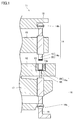
- FIG. 1 shows a schematic sectional view of a tableting device of an embodiment which is an example of the tableting device of the present invention.
- the tableting device 11 of the embodiment includes an upper punch 14, a lower punch 16, a die 13 having a mortar hole 13 a between the upper punch 14 and the lower punch 16, and an upper punch holding for holding the upper punch 14.
- the mortar 13 includes a rotating disk 12 provided at a predetermined interval in the circumferential direction.
- the upper iron guide rail 18 is connected to the head 14b at the upper end of the upper iron 14, and holds the upper iron 14 so as to be movable up and down with respect to the mortar hole 13a.
- the tip 14a of the upper eyelid 14 approaches the mortar hole 13a by the downward movement of the upper heel 14, and can be inserted into the mortar hole 13a.
- the tip 14a of the upper punch 14 can be separated from the mortar hole 13a by the upward movement of the upper ridge 14, and can be taken out from the mortar hole 13a.
- the lower iron guide rail 19 is connected to the head 16b at the lower end of the lower iron 16, and holds the lower iron 16 so as to be movable up and down with respect to the mortar hole 13a.
- the lower punch 16 is arranged so as to be movable up and down within a range in which at least a part of the tableting surface layer 20 of the tip 16a at the upper end of the lower punch 16 exists in the mortar hole 13a.
- the lower punch 16 is positioned at the lowermost end, at least a part of the tip 16a of the lower punch 16 is present in the mortar hole 13a, and the space in the mortar hole 13a is moved in accordance with the upward movement of the lower punch 16.
- the heel 16a of the lower heel 16 can be protruded from the upper end of the mortar hole 13a.
- the tablet can be tableted as follows. First, the head 14b of the upper collar 14 is connected to the upper collar guide rail 18 and the head 16b of the lower collar 16 is driven by the coaxial rotational drive of the rotating disk 12, the upper collar holding disk 15 and the lower collar holding disk 17. Is connected to the lower guide rail 19. Next, the lower punch 16 is positioned at a predetermined height by the lower guide rail 19, and the volume of the space in the mortar 13a by the tip 16a of the lower punch 16 becomes the amount of the powder material used for tableting. The volume is set to correspond.
- the powder material for tableting is filled in the space in the mortar hole 13a set to a volume corresponding to the amount of the powder material used for tableting.
- the upper heel guide rail 18 guides the upper heel 14 downward, and the heel tip 14a of the upper heel 14 is inserted from the upper end of the mortar hole 13a. The powder material is compressed between the tips 16a and tablets are compressed.
- the tablet after tableting can be taken out from the tableting device of the embodiment as follows, for example. First, the upper punch 14 is moved upward by the upper guide rail 18 and the tip 14a of the upper punch 14 is taken out from the mortar 13a. Next, the lower punch 16 is moved upward by the lower punch guide rail 19, and the tablet after tableting is lifted above the mortar 13 a by the tip 16 a of the lower punch 16. Thereafter, the tablet lifted above the mortar hole 13a is taken out of the tableting device by a scraper (not shown).
- the tableting surface layer 20 provided at the tip of at least one base material 10 of the tip 14a of the upper collar 14 and the tip 16a of the lower collar 16 includes nitrogen, a group 4A element, and the like. Containing crystalline yttrium oxide. Therefore, in the tableting device of the embodiment, the amount of the powder material adhering to the tableting surface of the tablet punch or mortar after the tableting of the powder material can be reduced.
- the group 4A element at least one kind of cation selected from the group consisting of titanium, zirconium and hafnium can be used.
- the yttrium oxide used for the tableting surface layer 20 is confirmed to be crystalline by a general crystallinity evaluation method such as an X-ray diffraction method, an electron beam diffraction method, a Raman spectroscopy method, or a channeling method. be able to.
- a general crystallinity evaluation method such as an X-ray diffraction method, an electron beam diffraction method, a Raman spectroscopy method, or a channeling method. be able to.
- the fact that the tableting surface layer 20 contains yttrium oxide containing nitrogen and a group 4A element can be specified by, for example, secondary ion mass spectrometry (SIMS) (Secondary Ion Mass Spectrometry). It is.
- SIMS secondary ion mass spectrometry
- the present inventors have found that crystalline yttrium oxide containing nitrogen and a 4A group element is excellent as a coating material for a tablet punch or a die.
- the present inventors infer about this as follows.
- anion vacancies anionic vacancies; lattice defects
- anion vacancies it is considered that organic matter adsorption is promoted due to the vacancies.
- one valence is larger than Y 3+ and is dissolved in Y 2 O 3 . That is, a cation of a group 4A element that substitutes Y 3+ may be added to yttrium oxide.
- the yttrium oxide of this embodiment is considered to be a solid solution having a crystal structure in which a part of yttrium is substituted by 4A element and a part of oxygen is substituted by nitrogen.
- the yttrium oxide 3 of the present embodiment can include at least one element selected from the group consisting of titanium (Ti), zirconium (Zr), hafnium (Hf), and rutherfordium (Rf) as a group 4A element, Especially, at least one of Zr and Hf can be included.
- the substitution amount (content) of the cation of the 4A group element in the yttrium oxide of the present embodiment can be converted to MeO 2 (Me is a 4A group element) and can exceed 0 mol% and be 20 mol% or less.
- the cation substitution amount is 20 mol% or less, for example, Zr or Hf is below the solid solution limit with respect to the yttrium oxide matrix, and composite oxide (consisting of yttrium oxide and zirconium oxide) or hafnium oxide is precipitated. Therefore, it is possible to further prevent the powder material from being easily attached.
- the substitution amount of the cation of the 4A element in the yttrium oxide of this embodiment can exceed 0 mol% and can be 10 mol% or less.
- the yttrium oxide of the present embodiment can contain at least one of Zr and Hf as a 4A group element, converted to MeO 2 (Me is a 4A group element), and exceeds 0 mol% and 20 mol. % Or less, and more than 0 mol% and 10 mol% or less.
- the content of nitrogen in the yttrium oxide of the present embodiment can be 0.01 mol% or more and 20 mol% or less.
- the content of nitrogen in the yttrium oxide of the present embodiment is 0.01 mol% or more, the amount of substitution of nitrogen in the yttrium oxide is not too small, and adhesion of the powder material can be further suppressed.
- the content of nitrogen in the yttrium oxide of this embodiment is 20 mol% or less, the crystal structure of yttrium oxide is further stabilized, so that the adhesion suppressing effect of the powder material can be maintained stably for a long period of time. Can do.
- the maximum nitrogen amount that can be substituted is preferably equal to the cation amount added to the same material.
- the nitrogen content (nitrogen ion (anion) concentration) in the yttrium oxide of this embodiment is: It can be 0.01 mol% or more and 10 mol% or less.
- the crystalline yttrium oxide containing nitrogen and 4A group element used for the tableting surface layer 20 is Hg, Ni, Cr, Co, Cu, Sn, Au, Pt, Pd, Sb, Ag, Fe or It does not have to contain a metal element or harmful metal that becomes an allergy-inducing component such as Zn.
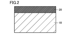
- FIG. 2 shows a schematic enlarged cross-sectional view of an example of a scissors used in the tableting device of the embodiment.
- the base material 10 used for the tip include iron-based materials (for example, stainless steel, carbon steel, alloy steel, alloy tool steel, high-speed steel, pre-hardened steel, etc.) or non-ferrous materials (copper-based, An aluminum-based or cemented carbide-based metal substrate can be used.
- iron-based materials for example, stainless steel, carbon steel, alloy steel, alloy tool steel, high-speed steel, pre-hardened steel, etc.
- non-ferrous materials copper-based
- An aluminum-based or cemented carbide-based metal substrate can be used.
- the substrate 10 can be formed by a conventional metal working method such as cutting or electric discharge machining.
- the tableting surface layer 20 containing yttrium oxide, nitrogen, and a cation of a group 4A element is formed on the surface of the tip of the substrate 10 by physical vapor deposition (PVD) such as sputtering or ion plating, for example. Can be formed.
- PVD physical vapor deposition
- the thickness of the tableting surface layer 20 can be, for example, about 0.1 ⁇ m to 5 ⁇ m. In the example shown in FIG. 2, when an adhesive layer is included between the base material 10 and the tableting surface layer 20, the thickness of the adhesive layer is, for example, about 0.01 ⁇ m to 1 ⁇ m. Can do.
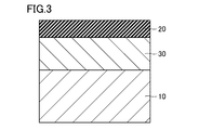
- FIG. 3 shows a schematic enlarged cross-sectional view of another example of the punch used in the tableting device of the embodiment.
- the example shown in FIG. 3 is characterized in that an intermediate layer 30 is provided between the base material 10 and the tableting surface layer 20.
- an intermediate layer 30 is provided between the base material 10 and the tableting surface layer 20.
- a layer having a part having higher hardness than the base material 10 and higher toughness than the tableting surface layer 20 can be used. Thereby, it can suppress that the tableting surface layer 20 cracks or the tableting surface layer 20 peels from the base material 10.
- the thickness of the intermediate layer 30 can be, for example, about 0.2 ⁇ m to 5 ⁇ m. In the example shown in FIG. 3, the thickness of the intermediate layer 30 can be set to about 0.1 ⁇ m to 5 ⁇ m, for example.
- FIG. 4 shows a schematic enlarged cross-sectional view of another example of the punch used in the tableting device of the embodiment.
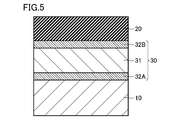
- the intermediate layer 30 includes a first adhesive layer 32A, a first buffer layer 31A, a second buffer layer 31B, and a second adhesive layer 32B stacked in this order from the base material 10 side. It is comprised from the laminated body made.
- An adhesive layer is a layer for improving the adhesive strength between the layers arrange
- the buffer layer is a layer for buffering the difference in hardness and / or toughness between the layers disposed on both sides of the buffer layer. Note that the adhesive layer may have a buffering action, and the buffer layer may have an adhesive action.
- FIG. 5 shows a schematic enlarged cross-sectional view of another example of the punch used in the tableting device of the embodiment.
- the intermediate layer 30 is configured from a laminate in which a first adhesive layer 32 ⁇ / b> A, a buffer layer 31, and a second adhesive layer 32 ⁇ / b> B are laminated in this order from the substrate 10 side.
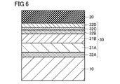
- FIG. 6 shows a schematic enlarged cross-sectional view of another example of the punch used in the tableting device of the embodiment.
- the intermediate layer 30 includes, from the base material 10 side, a first adhesive layer 32A, a first buffer layer 31A, a second buffer layer 31B, a second adhesive layer 32B, and a third adhesive.
- the layer 32 ⁇ / b> C and the fourth adhesive layer 32 ⁇ / b> D are configured by a stacked body in which the layers are stacked in this order.
- the buffer layer may be composed of a plurality of layers as shown in FIGS. 4 and 6, or may be composed of a single layer as shown in FIG.
- the adhesive layer may also be a single layer on each side of the buffer layer, as shown in FIGS. 4 and 5, and a plurality of adhesive layers may be provided on one side of the buffer layer, as shown in FIG.
- the layer may be composed of a single layer on the other surface side, or may be composed of a plurality of layers on each side of the buffer layer.
- an adhesive layer composed of a single layer or a plurality of layers may be provided between the buffer layers 31A and 31B which are substantially intermediate layers. Further, when an adhesive layer with another layer is provided on the buffer layer (substantially intermediate layer), the intermediate layer includes an adhesive layer.
- the buffer layer 31 and the base material 10 can be joined directly. Furthermore, in the example shown in FIG. 5, the buffer layer 31 and the tableting surface layer 20 can be directly joined.
- Both the buffer layer and the adhesive layer can be formed by physical vapor deposition (PVD) such as sputtering or ion plating.
- PVD physical vapor deposition
- the buffer layer can change in hardness so that the hardness increases from the base material 10 side made of a metal base material having a low hardness toward the tableting surface layer 20 side having a high hardness, for example.
- the hardness of the buffer layer 31B on the tableting surface layer 20 side is set to the buffer layer on the substrate 10 side made of a metal substrate or the like.
- the hardness can be changed stepwise so that the hardness is higher than that of the base material 10 at least on the surface portion on the tableting surface layer 20 side.
- the composition is changed in the thickness direction of the buffer layer (for example, the nitrogen concentration is reduced as the substrate 10 is made of a metal substrate or the like).
- the hardness can be continuously changed.
- the buffer layer is, for example, an MA-based nitride (M is titanium, chromium, nickel, zirconium, aluminum, or silicon, and A is nitrogen, carbon, or oxygen), carbide, or oxide. It consists of things.
- the adhesive layer for example, a metal containing at least one selected from the group consisting of titanium, chromium, nickel, zirconium, yttrium, aluminum, and silicon, or a layer containing a metal oxide can be used. That is, the adhesive layer is made of, for example, a single metal of titanium, chromium, nickel, zirconium, yttrium, aluminum, or silicon, or a mixture thereof, or an oxide of the metal simple substance or an oxide containing a plurality of the metals.
- the material constituting the buffer layer and the material constituting the adhesive layer can be appropriately selected and combined.
- the thickness (total) of the buffer layer can be, for example, about 0.2 ⁇ m to 5 ⁇ m.
- tablette only needs to include a portion that comes into contact with the tablet when the tablet is compressed, and is, for example, a tip portion that is detachable from the main body portion fixed to the tableting device. Also good.
- the “tablet surface layer” means the outermost surface layer of a punch or mortar having the contact surface in contact with the powder material to be tableted as the outermost surface during tableting.
- the upper punch 14, the lower punch 16 and the mortar 13 of the tableting device of the embodiment can be used for tableting at least one selected from the group consisting of pharmaceuticals, agricultural chemicals, fertilizers, foods and toilet articles.
- the medicinal product is a medicinal product given for diagnosing, treating or preventing human or animal diseases.
- a medicinal product which easily induces a tableting disorder for example, 2-[[6-[(3R) -3 -Amino-1-piperidinyl] -3,4-dihydro-3-methyl-2,4-dioxo-1 (2H) -pyrimidinyl] methyl] -benzonitrile (generic name: alogliptin or a salt thereof, ibuprofen, Vitamin C, ascorbic acid, trimebutine maleate and the like can be mentioned, but there are various other pharmaceuticals.
- tablette obstruction refers to, for example, sticking (a phenomenon in which powder adheres to the heel), binding (a phenomenon in which friction between the mortar and the tablet increases), and capping (the tablet peels into a cap shape). Phenomenon) or an undesired phenomenon that occurs during tableting, such as laminating (a phenomenon in which a tablet peels into a layer).
- Agricultural chemicals are drugs that are used to improve agricultural efficiency or preserve crops.
- Examples of agricultural chemicals include fungicides, fungicides, insecticides, herbicides, rodenticides, or plant growth regulators (for example, plant hormone agents). Etc.).
- a fertilizer is a nutrient for growing a plant, which is directly or indirectly given to a plant through soil, etc.
- a fertilizer for example, an organic fertilizer such as fish salmon, bone meal, plant oil lees
- chemical fertilizers such as ammonium sulfate, urea, ammonium nitrate, ammonium sulfate, ammonium phosphate, percalcite, barite, processed phosphoric fertilizer, potassium sulfate, potassium chloride, and the like.
- Foods are foods that humans eat mainly with meals, and examples of foods include tablet foods, health foods including supplements, or curry roux.
- Toiletries are intended for body cleaning, personal taste, or tastes. Toiletries include, for example, bathing agents, cleaning agents, non-chlorine slime removal agents, aromatic agents, or insect repellents. Can be mentioned.
- Comparative tablet upper and lower eyelids were prepared by forming a tableting surface layer made of hard chrome (HCr) plating on the surface of the tip of each of the upper and lower eyelids of the TSM standard B-Type.
- HCr hard chrome
- IBU ibuprofen
- lactose lactose
- corn starch a binder
- 63.2% by weight of crystalline cellulose as a disintegrant
- a fluidizing agent A mixed powder containing 1% by mass of silica was prepared. And by mixing 0.5 parts by mass of magnesium stearate as a lubricant with respect to 100 parts by mass of this mixed powder, the powder material No. 1 was produced.
- ⁇ Powder material No. Production of 2> A mixed powder containing 40% by mass of IBU, 8.3% by mass of lactose, 3.5% by mass of corn starch, 47.2% by mass of crystalline cellulose, and 1% by mass of silica was prepared. And by mixing 0.5 parts by mass of magnesium stearate with respect to 100 parts by mass of this mixed powder, the powder material No. 2 was produced.
- ⁇ Powder material No. 3 production> A mixed powder containing 60% by mass of IBU, 5.5% by mass of lactose, 2.3% by mass of corn starch, 31.2% by mass of crystalline cellulose, and 1% by mass of silica was prepared. And by mixing 0.5 parts by mass of magnesium stearate with respect to 100 parts by mass of this mixed powder, the powder material No. 3 was produced.
- the configuration of 3 is summarized in Table 1 below.
- the powder material No. 1 was prepared in the same manner and conditions as above except that the upper and lower irons of the comparative example were attached.
- 1-No. 3 was tableted to prepare tablets. And the surface state after tableting (after 100 shots) of each tableting surface layer of the upper collar and lower collar of the comparative example was confirmed.
- the pressurization method at the time of tableting was a two-stage pressurization method of preload and main pressure
- the load at the time of tableting was 9 to 12 kN
- the movement speed of the punch was 70 mm / second.
- the test conditions for the adhesion amount confirmation test are summarized in Table 2 below.
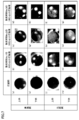
- FIG. 7 shows the powder material Nos. Of the upper and lower shells of Examples and Comparative Examples. 1-No. 3 shows the surface state of the tableting surface layer before tableting 3 and after tableting 100 shots.
- FIG. No. 1 surface condition of the tableting surface layer after tableting (FIG. 7 (b)), powder material no. 2, the surface condition of the tableting surface layer after tableting (FIG. 7C), and the powder material No. 3, the surface state of the tableting surface layer after tableting (FIG. 7 (d)) is respectively compared with the surface state of the tableting surface layer before tableting of the upper collar of the example (FIG. 7 (a)). There was not much change.
- the powder material No. No. 1 surface condition of the tableting surface layer after tableting (FIG. 7 (f)), powder material no. 2, the surface condition of the tableting surface layer after tableting (FIG. 7 (g)), and the powder material No. 3, the surface state of the tableting surface layer after tableting (FIG. 7 (h)) is also compared with the surface state of the tableting surface layer before tableting of the lower collar of the example (FIG. 7 (e)), respectively. There was not much change. Similar to the upper case of the examples, the powder material No. 1 and no. No adhesion of the powder material was confirmed on the tableting surface layer of the upper punch of the example after the tableting of No. 2. In the comparative example after tableting No. 3, only slight adhesion of the powder material was confirmed on the tableting surface layer of the upper punch.
- powder material No. No. 1 surface condition of the tableting surface layer after tableting (FIG. 7 (j)), powder material No. 2, the surface condition of the tableting surface layer after tableting (FIG. 7 (k)), and the powder material No. 3, the surface state of the tableting surface layer after tableting (FIG. 7 (l)) is respectively compared with the surface state of the tableting surface layer before tableting of the upper collar of the comparative example (FIG. 7 (i)). It was clearly changing.
- powder material no. A white film adheres to the tableting surface layer of the upper collar of the comparative example after tableting No. 1.
- the powder material No. 1 the surface condition of the tableting surface layer after tableting (FIG. 7 (n)), powder material No. 2, the surface condition of the tableting surface layer after tableting (FIG. 7 (o)), and the powder material No. 3, the surface state of the tableting surface layer after tableting (FIG. 7 (p)) is also compared to the surface state of the tableting surface layer before tableting of the lower arm of the comparative example (FIG. 7 (m)), respectively. It was clearly changing. Similar to the upper case of the comparative example, the powder material No. A white film is adhered to the tableting surface layer of the lower punch of the comparative example after tableting of No. 1. In the tableting surface layer of the lower eyelid of the comparative example after tableting No.
- the upper arm and the lower arm of the example can reduce the adhesion amount of the powder material as compared with the upper arm and the lower arm of the comparative example. Moreover, it was confirmed from the results shown in FIG. 7 that the amount of powder material attached tends to increase in proportion to the content of IBU in the powder material.
- the powder material No. 4 was produced. That is, the powder material No. No. 4 was a mixed powder containing 60% by mass of IBU, 5.5% by mass of lactose, 2.3% by mass of corn starch, 31.2% by mass of crystalline cellulose, and 1% by mass of silica.
- the upper punch and lower punch of the example were attached to the tableting machine (TK-TB-50KN) manufactured by Special Measurement Co., Ltd., and the tableting surface layer of each of the upper punch and lower punch of the example was used as the tableting surface.
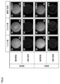
- powder material No. 4 was continuously tableted to prepare tablets. And the surface state of each tablet after 1-shot, 3-shot and 400-shot continuous tableting was confirmed.
- the powder material No. 1 was prepared in the same manner and conditions as above except that the upper and lower irons of the comparative example were attached. 4 was continuously tableted to prepare tablets. And the surface state of each tablet after 1-shot, 3-shot and 30-shot continuous tableting was confirmed.
- the surface state of the tablet was confirmed as follows. First, “MICRO SCOPE VHX-5000” manufactured by KEYENCE was used as a measuring instrument, and the surface of the tablet was photographed with a CCD camera under a coaxial incident and illumination condition of 20 with a lens magnification of 20 ⁇ . Then, binarization processing is performed on the image of the surface of the photographed tablet, and the threshold value is set so that the cloudy surface, minute irregularities and missing part of the tablet surface are darkly displayed, and only the smooth part is displayed in red. The area ratio of the red part (area ratio of the smooth part) [%] to the area of the entire surface of the tablet was calculated. The result is shown in FIG.
- the area ratio of the smooth portion on the surface of the tablet after continuous tableting of 1 shot, 3 shots and 400 shots is These are 71%, 70% and 80%, respectively, and the smoothness of the surface of the tablet is maintained even after 400 shots of continuous tableting, and the tablet can be shipped as a product (in FIG. 8, “ OK ”) was confirmed.
- the upper and lower eyelids of the example can improve the smoothness of the surface of the tablet after continuous tableting, compared to the upper and lower eyelids of the comparative example. It was confirmed that long-term use is possible.
- the smoothness of the tablet surface after tableting is usually very low. Nevertheless, in the upper and lower punches of the examples, the above smoothness could be achieved under very severe conditions such as continuous tableting of the powder material not containing the lubricant. It is considered that the tableting surface layer of the upper and lower punches is very excellent as a tableting surface.
- the tablet was taken out by the scraper after each shot of continuous tableting, and the maximum value [N] of the load applied to the scraper at the time of taking out the tablet was measured.
- the result is shown in FIG.
- the horizontal axis indicates the number of shots of continuous tableting, and the vertical axis indicates the maximum load value [N] of the scraper.
- the maximum load value of the scraper when using the upper and lower punches of the comparative example is the case where the upper and lower punches of the example are used. It was confirmed that the load was lower than the maximum load of the scraper. This is because, since the white film adheres to the tableting surface layer of the upper and lower punches of the comparative example after tableting, the maximum frictional force between the white film adhered to the tableting surface layer and the tablet surface is obtained. It is considered that the value was measured as the maximum load value of the scraper.
- the maximum value of the frictional force between the lower tableting surface layer and the tablet surface Is considered to be measured as the maximum load of the scraper.
- the upper and lower eyelids of the example can improve the smoothness of the surface of the tablet after continuous tableting and can be used for a longer period of time than the upper and lower eyelids of the comparative example. It was confirmed that there was.
- the tableting surface layer containing crystalline yttrium oxide containing nitrogen and a group 4A element is used for both upper and lower punches. It may be used only for either the upper or lower arm, and instead of the upper arm and / or the lower arm or together with the upper and / or lower arm, at least a part of the contact surface with the powder material of the mortar May be used.
- Tableting device 12 rotary disc, 13 mortar, 14 upper punch, 14a tip, 14b head, 15 upper punch holding plate, 16 lower punch, 16a tip, 16b head, 17 lower punch holding plate, 18 upper ⁇ guide rail, 19 lower guide rail, 20 tableting surface layer, 30 intermediate layer, 31 buffer layer, 31A first buffer layer, 31B second buffer layer, 32A first adhesive layer, 32B second bond Layer, 32C third adhesive layer, 32D fourth adhesive layer.
Landscapes
- Chemical & Material Sciences (AREA)
- Health & Medical Sciences (AREA)
- Mechanical Engineering (AREA)
- Engineering & Computer Science (AREA)
- Life Sciences & Earth Sciences (AREA)
- Materials Engineering (AREA)
- General Health & Medical Sciences (AREA)
- Public Health (AREA)
- Veterinary Medicine (AREA)
- Chemical Kinetics & Catalysis (AREA)
- Pharmacology & Pharmacy (AREA)
- Animal Behavior & Ethology (AREA)
- Medicinal Chemistry (AREA)
- Metallurgy (AREA)
- Organic Chemistry (AREA)
- Medicinal Preparation (AREA)
- Physical Vapour Deposition (AREA)
- Medical Preparation Storing Or Oral Administration Devices (AREA)
- Agricultural Chemicals And Associated Chemicals (AREA)
Priority Applications (5)
| Application Number | Priority Date | Filing Date | Title |
|---|---|---|---|
| KR1020187031057A KR102252310B1 (ko) | 2016-04-15 | 2016-11-18 | 타정공이 또는 절구 및 그것을 포함하는 타정장치 |
| SG11201808033WA SG11201808033WA (en) | 2016-04-15 | 2016-11-18 | Tableting punch or die and tableting machine including the same |
| CN201680084641.7A CN109070515B (zh) | 2016-04-15 | 2016-11-18 | 压片杵或臼和包含其的压片装置 |
| US16/093,555 US10792880B2 (en) | 2016-04-15 | 2016-11-18 | Tableting punch or die and tableting machine including the same |
| EP16898693.3A EP3446865A4 (en) | 2016-04-15 | 2016-11-18 | PUNCH AND MORTAR FOR TABLETING AND TABLETING MACHINE THEREWITH |
Applications Claiming Priority (2)
| Application Number | Priority Date | Filing Date | Title |
|---|---|---|---|
| JP2016081926A JP6541608B2 (ja) | 2016-04-15 | 2016-04-15 | 打錠杵又は臼およびそれを含む打錠装置 |
| JP2016-081926 | 2016-04-15 |
Publications (2)
| Publication Number | Publication Date |
|---|---|
| WO2017179235A1 true WO2017179235A1 (ja) | 2017-10-19 |
| WO2017179235A9 WO2017179235A9 (ja) | 2018-08-23 |
Family
ID=60042581
Family Applications (1)
| Application Number | Title | Priority Date | Filing Date |
|---|---|---|---|
| PCT/JP2016/084238 Ceased WO2017179235A1 (ja) | 2016-04-15 | 2016-11-18 | 打錠杵又は臼およびそれを含む打錠装置 |
Country Status (8)
| Country | Link |
|---|---|
| US (1) | US10792880B2 (enExample) |
| EP (1) | EP3446865A4 (enExample) |
| JP (1) | JP6541608B2 (enExample) |
| KR (1) | KR102252310B1 (enExample) |
| CN (1) | CN109070515B (enExample) |
| SG (1) | SG11201808033WA (enExample) |
| TW (1) | TWI644664B (enExample) |
| WO (1) | WO2017179235A1 (enExample) |
Cited By (1)
| Publication number | Priority date | Publication date | Assignee | Title |
|---|---|---|---|---|
| GB2567886B (en) * | 2017-10-31 | 2022-11-23 | I Holland Ltd | Tablet tools |
Families Citing this family (3)
| Publication number | Priority date | Publication date | Assignee | Title |
|---|---|---|---|---|
| JP7048447B2 (ja) * | 2018-08-01 | 2022-04-05 | 沢井製薬株式会社 | 錠剤のバインディングの評価方法及び評価装置 |
| KR102012512B1 (ko) | 2019-04-23 | 2019-08-20 | (주)트루나스 | 고형 조미료 타정 장치 |
| CN111589899B (zh) * | 2020-05-28 | 2025-07-25 | 智盛信息科技(东莞)有限公司 | 后盖加工系统 |
Citations (3)
| Publication number | Priority date | Publication date | Assignee | Title |
|---|---|---|---|---|
| JPH0780851A (ja) * | 1993-09-17 | 1995-03-28 | Ricoh Co Ltd | 複合型光学素子成形用金型及び複合型光学素子成形方法 |
| JP2006315076A (ja) * | 2005-05-16 | 2006-11-24 | Fuyo Kogyo Kk | 錠剤の打錠杵又は臼 |
| WO2009098904A1 (ja) * | 2008-02-08 | 2009-08-13 | Ltt Bio-Pharma Co., Ltd. | 錠剤を打錠する杵又は臼の打錠表面の処理方法とこの方法で表面処理された杵又は臼とこの杵又は臼で打錠された錠剤 |
Family Cites Families (6)
| Publication number | Priority date | Publication date | Assignee | Title |
|---|---|---|---|---|
| JPS63149098A (ja) | 1986-12-11 | 1988-06-21 | Toshiba Corp | 粉末成形用金型 |
| US5535811A (en) * | 1987-01-28 | 1996-07-16 | Remet Corporation | Ceramic shell compositions for casting of reactive metals |
| US5609922A (en) * | 1994-12-05 | 1997-03-11 | Mcdonald; Robert R. | Method of manufacturing molds, dies or forming tools having a cavity formed by thermal spraying |
| US20110159137A1 (en) | 2008-09-08 | 2011-06-30 | Shinji Ando | Tablet compression die |
| JP5561992B2 (ja) | 2009-10-09 | 2014-07-30 | Towa株式会社 | 低密着性材料、防汚性材料、成形型、及び、それらの製造方法 |
| CN102296261A (zh) | 2010-06-23 | 2011-12-28 | 海洋王照明科技股份有限公司 | 镀铝液、热浸镀铝方法以及其制备的金属器件 |
-
2016
- 2016-04-15 JP JP2016081926A patent/JP6541608B2/ja active Active
- 2016-11-18 WO PCT/JP2016/084238 patent/WO2017179235A1/ja not_active Ceased
- 2016-11-18 CN CN201680084641.7A patent/CN109070515B/zh active Active
- 2016-11-18 SG SG11201808033WA patent/SG11201808033WA/en unknown
- 2016-11-18 US US16/093,555 patent/US10792880B2/en active Active
- 2016-11-18 EP EP16898693.3A patent/EP3446865A4/en active Pending
- 2016-11-18 KR KR1020187031057A patent/KR102252310B1/ko active Active
- 2016-11-23 TW TW105138361A patent/TWI644664B/zh active
Patent Citations (3)
| Publication number | Priority date | Publication date | Assignee | Title |
|---|---|---|---|---|
| JPH0780851A (ja) * | 1993-09-17 | 1995-03-28 | Ricoh Co Ltd | 複合型光学素子成形用金型及び複合型光学素子成形方法 |
| JP2006315076A (ja) * | 2005-05-16 | 2006-11-24 | Fuyo Kogyo Kk | 錠剤の打錠杵又は臼 |
| WO2009098904A1 (ja) * | 2008-02-08 | 2009-08-13 | Ltt Bio-Pharma Co., Ltd. | 錠剤を打錠する杵又は臼の打錠表面の処理方法とこの方法で表面処理された杵又は臼とこの杵又は臼で打錠された錠剤 |
Non-Patent Citations (1)
| Title |
|---|
| See also references of EP3446865A4 * |
Cited By (1)
| Publication number | Priority date | Publication date | Assignee | Title |
|---|---|---|---|---|
| GB2567886B (en) * | 2017-10-31 | 2022-11-23 | I Holland Ltd | Tablet tools |
Also Published As
| Publication number | Publication date |
|---|---|
| SG11201808033WA (en) | 2018-10-30 |
| KR102252310B1 (ko) | 2021-05-14 |
| KR20180136965A (ko) | 2018-12-26 |
| WO2017179235A9 (ja) | 2018-08-23 |
| EP3446865A1 (en) | 2019-02-27 |
| US10792880B2 (en) | 2020-10-06 |
| CN109070515A (zh) | 2018-12-21 |
| JP6541608B2 (ja) | 2019-07-10 |
| TW201737886A (zh) | 2017-11-01 |
| EP3446865A4 (en) | 2019-11-20 |
| TWI644664B (zh) | 2018-12-21 |
| US20190176428A1 (en) | 2019-06-13 |
| JP2017189812A (ja) | 2017-10-19 |
| CN109070515B (zh) | 2021-03-19 |
Similar Documents
| Publication | Publication Date | Title |
|---|---|---|
| WO2017179235A1 (ja) | 打錠杵又は臼およびそれを含む打錠装置 | |
| EP1750647B1 (en) | Pharmaceutical tablets having a separation mark positioned on the side of said tablets | |
| UA110773C2 (uk) | Спосіб одержання порошків, що містять нано- і мікрочастинки | |
| TW200909592A (en) | Cemented carbide, cutting tool, and cutting device | |
| JP6492512B2 (ja) | 歯科用の被切削加工用ブランク材、粉末冶金用金属粉末、歯科用の陶材焼付用メタルフレームおよび歯科用補綴物 | |
| KR20220137666A (ko) | Bi853520과 화학요법 약물의 병용 | |
| EP4241837A3 (en) | Nicotinamide mononucleotide derivatives in the treatment and prevention of sickle cell disease | |
| WO2018070195A1 (ja) | 表面被覆切削工具 | |
| EP2853229B1 (en) | Dental blank to be machined, metal powder for powder metallurgy, dental metal frame for porcelain bonding, and dental prosthesis | |
| JPH07116048B2 (ja) | パーキンソン症候群の治療用薬剤 | |
| EP2029116A1 (en) | Segmented pharmaceutical dosage forms | |
| WO2012048692A2 (de) | Wendeschneidplatte und verfahren zu deren herstellung | |
| WO2022097670A1 (ja) | 生体適合性材料及びその製造方法 | |
| JP3159572B2 (ja) | 高強度被覆物体 | |
| CN103302323B (zh) | 耐崩刀性、耐缺损性优异的表面包覆切削工具 | |
| JP7139842B2 (ja) | HMB-Ca含有被覆物並びにそれらを含有する錠剤 | |
| KR20220152231A (ko) | 고농도 비타민을 포함하는 노인성 안구 질환용 조성물 및 방법 | |
| JP6578532B2 (ja) | 被覆層を有する耐熱合金製工具および加工装置 | |
| JP6285044B2 (ja) | チタン製スパッタリングターゲット及びその製造方法 | |
| DE112018007875T5 (de) | Hartbeschichtung und mit Hartbeschichtung bedecktes Element | |
| Fernandez et al. | Antimicrobial Activity against Escherichia coli of Cu-Ni Nanoalloy and Combination of Ag Nanoparticles, Obtained by Different Method | |
| JPH05287323A (ja) | 結晶配向の被覆焼結合金 | |
| EP1666076A3 (en) | Material for repairing biological tissues,product for repairing biological tissues, and method of manufacturing material for repairing biological tissues | |
| EP3079696A1 (de) | Adenosin a1 agonisten als arzneimittel gegen nierenerkrankungen | |
| Abdelhakim | Study of the effect of kinetic factors on the biological activity of metal oxide nanoparticles prepared using date waste and same local plants |
Legal Events
| Date | Code | Title | Description |
|---|---|---|---|
| WWE | Wipo information: entry into national phase |
Ref document number: 11201808033W Country of ref document: SG |
|
| NENP | Non-entry into the national phase |
Ref country code: DE |
|
| WWE | Wipo information: entry into national phase |
Ref document number: 2016898693 Country of ref document: EP |
|
| ENP | Entry into the national phase |
Ref document number: 20187031057 Country of ref document: KR Kind code of ref document: A |
|
| ENP | Entry into the national phase |
Ref document number: 2016898693 Country of ref document: EP Effective date: 20181025 |
|
| 121 | Ep: the epo has been informed by wipo that ep was designated in this application |
Ref document number: 16898693 Country of ref document: EP Kind code of ref document: A1 |