WO2017170833A1 - コイルばね - Google Patents
コイルばね Download PDFInfo
- Publication number
- WO2017170833A1 WO2017170833A1 PCT/JP2017/013172 JP2017013172W WO2017170833A1 WO 2017170833 A1 WO2017170833 A1 WO 2017170833A1 JP 2017013172 W JP2017013172 W JP 2017013172W WO 2017170833 A1 WO2017170833 A1 WO 2017170833A1
- Authority
- WO
- WIPO (PCT)
- Prior art keywords
- coil
- wire
- coil axis
- coil spring
- axis direction
- Prior art date
- Legal status (The legal status is an assumption and is not a legal conclusion. Google has not performed a legal analysis and makes no representation as to the accuracy of the status listed.)
- Ceased
Links
Images


Classifications
-
- F—MECHANICAL ENGINEERING; LIGHTING; HEATING; WEAPONS; BLASTING
- F16—ENGINEERING ELEMENTS AND UNITS; GENERAL MEASURES FOR PRODUCING AND MAINTAINING EFFECTIVE FUNCTIONING OF MACHINES OR INSTALLATIONS; THERMAL INSULATION IN GENERAL
- F16F—SPRINGS; SHOCK-ABSORBERS; MEANS FOR DAMPING VIBRATION
- F16F1/00—Springs
- F16F1/02—Springs made of steel or other material having low internal friction; Wound, torsion, leaf, cup, ring or the like springs, the material of the spring not being relevant
- F16F1/04—Wound springs
- F16F1/047—Wound springs characterised by varying pitch
-
- F—MECHANICAL ENGINEERING; LIGHTING; HEATING; WEAPONS; BLASTING
- F16—ENGINEERING ELEMENTS AND UNITS; GENERAL MEASURES FOR PRODUCING AND MAINTAINING EFFECTIVE FUNCTIONING OF MACHINES OR INSTALLATIONS; THERMAL INSULATION IN GENERAL
- F16F—SPRINGS; SHOCK-ABSORBERS; MEANS FOR DAMPING VIBRATION
- F16F1/00—Springs
- F16F1/02—Springs made of steel or other material having low internal friction; Wound, torsion, leaf, cup, ring or the like springs, the material of the spring not being relevant
- F16F1/04—Wound springs
- F16F1/06—Wound springs with turns lying in cylindrical surfaces
-
- F—MECHANICAL ENGINEERING; LIGHTING; HEATING; WEAPONS; BLASTING
- F16—ENGINEERING ELEMENTS AND UNITS; GENERAL MEASURES FOR PRODUCING AND MAINTAINING EFFECTIVE FUNCTIONING OF MACHINES OR INSTALLATIONS; THERMAL INSULATION IN GENERAL
- F16F—SPRINGS; SHOCK-ABSORBERS; MEANS FOR DAMPING VIBRATION
- F16F2234/00—Shape
- F16F2234/02—Shape cylindrical
-
- F—MECHANICAL ENGINEERING; LIGHTING; HEATING; WEAPONS; BLASTING
- F16—ENGINEERING ELEMENTS AND UNITS; GENERAL MEASURES FOR PRODUCING AND MAINTAINING EFFECTIVE FUNCTIONING OF MACHINES OR INSTALLATIONS; THERMAL INSULATION IN GENERAL
- F16F—SPRINGS; SHOCK-ABSORBERS; MEANS FOR DAMPING VIBRATION
- F16F2238/00—Type of springs or dampers
- F16F2238/02—Springs
- F16F2238/026—Springs wound- or coil-like
Definitions
- the present invention relates to a coil spring.
- a coil spring in which a wire is wound around a coil axis has been widely used.
- this type of coil spring when a large number of coil springs are randomly accommodated together, they are entangled with each other, for example, there is a risk of reducing manufacturing efficiency.
- a plurality of closely wound portions are formed for contacting or approaching the wire in the coil axis direction. Accordingly, the closely wound portion is prevented from entering a gap in the coil axis direction (hereinafter referred to as a wire rod gap) between the wire rods adjacent to each other in the coil axis direction of another coil spring.
- the present invention has been made in consideration of such circumstances, and an object of the present invention is to provide a coil spring that can prevent mutual intertwining without increasing weight and cost.
- a coil spring according to an aspect of the present invention is a coil spring in which a wire is wound around a coil axis, and the coil axis direction of a plurality of wires that are adjacent to each other in the coil axis direction at an end in the coil axis direction. Is provided with a corresponding portion in which the size of the coil spring is equivalent to the maximum value of the gap in the coil axis direction between the wire rods adjacent to each other in the coil axis direction of the coil spring.
- the gap in the coil axial direction between the adjacent wires in the direction of the coil is smaller than the wire height in the effective winding portion of the coil spring, and the correspondence is performed around the coil axis at the end in the coil axial direction.
- a gap extending from the portion to the end of the wire is between the adjacent wire on the inner side in the coil axial direction, and the gap in the coil axial direction extends from the corresponding portion around the coil axis to the end of the wire. Gradually, it is smaller in accordance buy.
- the gap in the coil axis direction between the corresponding portion and the wire adjacent to the corresponding portion on the inner side in the coil axis direction (hereinafter referred to as the wire rod gap) is the wire height in the effective winding portion. It is smaller than this. Therefore, even if the corresponding portion of one coil spring tries to enter the wire gap of the other coil spring, the wire in the effective winding portion of the other coil spring has a coil shaft in the corresponding portion in the one coil spring and the corresponding portion. It will interfere with at least one of the adjacent wires in the direction.
- the wire in the effective winding portion of the other coil spring enters the wire gap between the corresponding portion of one coil spring and the wire adjacent to the corresponding portion on the inner side in the coil axial direction. It becomes possible to prevent. As a result, it is possible to prevent the wire in the effective winding portion of the other coil spring from being strongly sandwiched by the wire of one coil spring from both sides in the coil axial direction and becoming difficult to come off. Therefore, for example, it is possible to prevent the coil springs from being entangled without increasing the length of the wire and forming a plurality of densely wound portions on the coil spring.
- the coil spring is a closed-end coil spring in which the end portion of the wire is superimposed on a wire rod adjacent to the end portion on the inner side in the coil axial direction, and the corresponding portion is in the coil axial direction. And may be configured by a pair of adjacent wires.
- the coil spring is a closed end, the above-described effects are remarkably achieved. Further, since the corresponding portion is constituted by a pair of wires that are adjacent to each other in the coil axis direction, the length of the wire can be reliably suppressed.
- the coil spring according to the present invention can prevent entanglement with each other without increasing weight and cost.
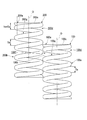
- FIG. 1 It is a side view of the coil spring of one embodiment concerning the present invention. It is a schematic diagram of the coil spring shown in FIG. It is a side view of the conventional coil spring.
- the size hs in the coil axis O direction of the entire plurality of wires adjacent to each other in the coil axis O direction at the end in the coil axis O direction is the coil spring 100.
- 200 corresponding to the maximum value Sa of the gap of the wire rods 100a, 200a is provided.
- the coil springs 100 and 200 are closed end springs having effective winding portions 100e and 200b of equal pitch. Therefore, the maximum value Sa of the wire gap is the same over almost the entire area of the effective winding portions 100e and 200b.
- the corresponding portion 100 a of one coil spring 100 enters the wire material gap of the other coil spring 200.
- the wire in the effective winding portion 200b of the other coil spring 200 includes a corresponding portion 100a in one coil spring 100 and a wire 100b adjacent to the corresponding portion 100a on the inner side in the coil axis O direction.
- the wire enters the gap 100f between the wires.
- the portions extending from the corresponding portions 100a and 200a to the end portions 100c and 200c of the wire along the coil axis O are inside the coil axis O direction.
- the wire gaps 100d and 200d formed between the adjacent wires 100g and 200g gradually become smaller along the coil axis O from the corresponding portions 100a and 200a toward the end portions 100c and 200c of the wire. Therefore, the wire in the other coil spring 200 tends to enter deeply into the wire gap 100d in the one coil spring 100.
- the wire of the other coil spring 200 is strongly sandwiched from both sides in the direction of the coil axis O by the wire of the one coil spring 100 and is difficult to come off. In this way, the coil springs 100 and 200 are entangled with each other.
- the coil spring according to the present invention was created in view of the above knowledge.
- an embodiment of a coil spring according to the present invention will be described with reference to FIGS. 1 and 2.
- the coil springs 1a and 1b of the present embodiment are formed by winding a plurality of wire rods continuously around the coil axis O.
- the coil springs 1a and 1b are made of, for example, a metal material.
- the outer diameters of the coil springs 1a and 1b are the same over the entire length in the coil axis O direction.
- the wire of the effective winding portion 13 is formed in a circular shape in a cross-sectional view orthogonal to the central axis.
- the outer diameter of the wire in the effective winding portion 13 is the same over the entire length.
- the coil springs 1a and 1b are closed-end coil springs in which the end w1 of the wire is in contact with and overlapped with the adjacent wire on the inner side in the coil axis O direction with respect to the end w1.
- the end portion w1 of the wire rod is formed with a flat surface extending in the horizontal direction orthogonal to the coil axis O direction and facing outward in the coil axis O direction, for example, by grinding.
- An open end coil spring may be employed instead of the closed end.
- the gap in the coil axis O direction between the wires adjacent to each other in the coil axis O direction (hereinafter referred to as the wire gap) is maximized at the center of the coil springs 1a and 1b in the coil axis O direction, and is outside the coil axis O direction. It gets smaller gradually as you go.
- a portion of the wire from the end edge w2 to about 180 ° centering on the coil axis O is in contact with and overlapped with the adjacent wire on the inner side in the coil axis O direction.
- the portion from the end edge w2 to about 180 ° centering on the coil axis O is overlapped in contact with the adjacent wire on the inner side in the coil axis O direction, and the other portions are in the coil axis O direction.
- the portion from the end edge w2 to a portion exceeding about 180 ° centering on the coil axis O may be abutted and overlapped with the adjacent wire rod on the inner side in the coil axis O direction.
- the size hs in the coil axis O direction of all of the plurality of wires adjacent to each other in the coil axis O direction at the ends of the coil springs 1a and 1b in the coil axis O direction is the wire material in the coil springs 1a and 1b.
- a corresponding portion 11 that is equivalent to the maximum value Sa of the gap is provided.
- the corresponding portion 11 is configured by a pair of wires that are adjacent to each other in the coil axis O direction.
- the corresponding portion 11 may be configured by three or more wires that are adjacent to each other in the coil axis O direction.
- Corresponding portion 11 includes a part of the end face of coil springs 1a and 1b in the direction of coil axis O.
- the outer end edge of the corresponding portion 11 in the coil axis O direction is between the end edge w2 and the portion 360 ° away from the end of the coil axis O, that is, 1.0 turn away from the end edge w2. Located between the parts.
- the corresponding portion 11 is located between the end edge w2 and the portion about 540 ° away from the end of the wire axis O, that is, the portion about 1.5 turns away from the end edge w2. .
- the corresponding portion 11 is a portion of the wire that is a little less than about 180 ° from the end edge w2 around the coil axis O, and a portion that is a little less than about 540 ° around the coil axis O from the end edge w2. Are in contact with each other in the coil axis O direction.
- the portion where the wire is slightly less than 0.5 turns away from the end edge w 2 and the portion less than 1.5 turns away from the end edge w 2 are in contact with each other in the coil axis O direction and overlapped. It has become a part.
- the wire height h is the size of the wire in the direction of the coil axis O. That is, the wire height h is obtained by dividing the diameter d of the wire in the effective winding portion 13 by cos ⁇ , where the lead angle is ⁇ .
- the wire gap is maximized at the central portion of the coil springs 1a and 1b in the direction of the coil axis O, and gradually decreases toward the outside in the direction of the coil axis O. Therefore, the lead angle is not constant in the effective winding portion 13, and the wire height h is not constant.
- the directly below gap Sb is smaller than the minimum value of the wire height h in the effective winding portion 13.
- the direct gap Sb is smaller than the diameter d of the wire in the effective winding portion 13.
- the directly-underlying gap Sb may be equal to or larger than the diameter d of the wire in the effective winding portion 13.
- the portion extending from the corresponding portion 11 to the end portion w1 side of the wire along the coil axis O is between the adjacent wire 14 inside the coil axis O direction.
- the wire gap Sc (hereinafter referred to as the end gap) Sc is gradually reduced from the corresponding portion 11 toward the end w1 of the wire along the coil axis O.
- the directly below gap Sb is smaller than the wire height h in the effective winding portion 13. Therefore, even if the corresponding portion 11 of the one coil spring 1a tries to enter the wire gap of the other coil spring 1b, the wire in the effective winding portion 13 of the other coil spring 1b is changed to the corresponding portion 11 of the one coil spring 1a. , And at least one of the wires 12 adjacent to the corresponding portion 11 on the inner side in the coil axis O direction. Thereby, it becomes possible to prevent the wire in the effective winding part 13 of the other coil spring 1b from entering deeply into the end part gap Sc through the gap Sb immediately below the one coil spring 1a.
- the wire in the effective winding portion 13 of the other coil spring 1b is strongly sandwiched from both sides in the direction of the coil axis O by the portion defining the end clearance Sc among the wires of the one coil spring 1a, and is difficult to come off. Can be prevented. Therefore, for example, it is possible to prevent the coil springs from being entangled without increasing the length of the wire and forming a plurality of densely wound portions on the coil spring.
- the coil springs 1a and 1b are closed-end coil springs, the above-described effects are remarkably achieved.
- the corresponding portion 11 is configured by a pair of wires that are adjacent to each other in the direction of the coil axis O, the length of the wire can be reliably suppressed.
- the configuration in which the adjacent wires in the coil axis O direction are in contact with each other as the corresponding portion 11 is shown.
- a configuration in which wires adjacent in the coil axis O direction are separated from each other in the coil axis O direction may be employed.
- the coil spring according to the present invention can prevent entanglement with each other without increasing weight and cost.
Landscapes
- Engineering & Computer Science (AREA)
- General Engineering & Computer Science (AREA)
- Mechanical Engineering (AREA)
- Springs (AREA)
Abstract
コイルばね(1a、1b)であって、コイル軸方向の端部に、コイル軸方向で互いに隣り合う複数の線材全体のコイル軸方向の大きさ(hs)が、前記コイルばねにおけるコイル軸方向で互いに隣り合う線材同士のコイル軸方向の隙間の最大値(Sa)と同等となる対応部分(11)が設けられ、前記対応部分と、前記対応部分に対してコイル軸方向の内側で隣り合う線材(12)と、の間のコイル軸方向の隙間(Sb)が、前記コイルばねの有効巻部(13)における素線高さ(h)より小さく、コイル軸方向の前記端部において、コイル軸回りに沿って前記対応部分から線材の末端部(w1)側にわたる部分が、コイル軸方向の内側で隣り合う線材(14)との間でなすコイル軸方向の隙間(Sc)が、コイル軸回りに沿って前記対応部分から線材の前記末端部側に向かうに従い漸次、小さくなっている。
Description
本発明は、コイルばねに関する。
本願は、2016年3月31日に、日本に出願された特願2016-073519号に基づき優先権を主張し、その内容をここに援用する。
本願は、2016年3月31日に、日本に出願された特願2016-073519号に基づき優先権を主張し、その内容をここに援用する。
従来から、線材がコイル軸回りに巻回されてなるコイルばねが広く用いられている。
この種のコイルばねにおいては、多数のコイルばねをランダムにまとめて収容する等したときに互いに絡み合い、例えば製造効率を低減させる等のおそれがあった。
下記特許文献1に示されるコイルばねにおいては、線材をコイル軸方向に当接若しくは近接させる複数の密巻部分が形成される。これにより、密巻部分が、他のコイルばねにおけるコイル軸方向で互いに隣り合う線材同士の間のコイル軸方向の隙間(以下、線材隙間という)に進入することを抑える。
この種のコイルばねにおいては、多数のコイルばねをランダムにまとめて収容する等したときに互いに絡み合い、例えば製造効率を低減させる等のおそれがあった。
下記特許文献1に示されるコイルばねにおいては、線材をコイル軸方向に当接若しくは近接させる複数の密巻部分が形成される。これにより、密巻部分が、他のコイルばねにおけるコイル軸方向で互いに隣り合う線材同士の間のコイル軸方向の隙間(以下、線材隙間という)に進入することを抑える。
しかしながら、特許文献1に示されるコイルばねでは、長い線材が必要となり、重量やコストが増大する。
本発明は、このような事情を考慮してなされたもので、重量やコストを増大させることなく、相互に絡み合うのを防ぐことができるコイルばねを提供することを目的とする。
本発明の一態様のコイルばねは、線材がコイル軸回りに巻回されてなるコイルばねであって、コイル軸方向の端部に、コイル軸方向で互いに隣り合う複数の線材全体のコイル軸方向の大きさが、前記コイルばねにおけるコイル軸方向で互いに隣り合う線材同士のコイル軸方向の隙間の最大値と同等となる対応部分が設けられ、前記対応部分と、前記対応部分に対してコイル軸方向の内側で隣り合う線材と、の間のコイル軸方向の隙間が、前記コイルばねの有効巻部における素線高さより小さく、コイル軸方向の前記端部において、コイル軸回りに沿って前記対応部分から線材の末端部側にわたる部分が、コイル軸方向の内側で隣り合う線材との間でなすコイル軸方向の隙間が、コイル軸回りに沿って前記対応部分から線材の前記末端部側に向かうに従い漸次、小さくなっている。
本発明によれば、対応部分と、対応部分に対してコイル軸方向の内側で隣り合う線材と、の間のコイル軸方向の隙間(以下、線材隙間という)が、有効巻部における素線高さより小さくなっている。したがって、一方のコイルばねの対応部分が、他方のコイルばねの線材隙間に進入しようとしても、他方のコイルばねの有効巻部における線材が、一方のコイルばねにおける対応部分、および対応部分にコイル軸方向の内側で隣り合う線材のうちの少なくとも一方に干渉することとなる。
これにより、一方のコイルばねにおける、対応部分と、対応部分に対してコイル軸方向の内側で隣り合う線材と、の間の線材隙間に、他方のコイルばねの有効巻部における線材が進入するのを防ぐことが可能になる。この結果、他方のコイルばねの有効巻部における線材が、一方のコイルばねの線材によってコイル軸方向の両側から強く挟み込まれて抜けにくくなるのを防ぐことができる。
したがって、例えば線材の長さを長くしてコイルばねに複数の密巻部分などを形成しなくても、コイルばね同士の絡み合いが発生するのを防ぐことができる。
これにより、一方のコイルばねにおける、対応部分と、対応部分に対してコイル軸方向の内側で隣り合う線材と、の間の線材隙間に、他方のコイルばねの有効巻部における線材が進入するのを防ぐことが可能になる。この結果、他方のコイルばねの有効巻部における線材が、一方のコイルばねの線材によってコイル軸方向の両側から強く挟み込まれて抜けにくくなるのを防ぐことができる。
したがって、例えば線材の長さを長くしてコイルばねに複数の密巻部分などを形成しなくても、コイルばね同士の絡み合いが発生するのを防ぐことができる。
ここで、前記コイルばねは、線材の前記末端部が、前記末端部に対してコイル軸方向の内側で隣り合う線材に重ね合わされたクローズドエンドのコイルばねであり、前記対応部分は、コイル軸方向で互いに隣り合う一対の線材により構成されてもよい。
この場合、クローズドエンドのコイルばねとなっているので、前述の作用効果が顕著に奏功される。また対応部分が、コイル軸方向で互いに隣り合う一対の線材により構成されているので、線材の長さを確実に抑えることができる。
本発明に係るコイルばねによれば、重量やコストを増大させることなく、相互に絡み合うのを防ぐことができる。
本願発明者等が鋭意検討した結果、次の知見を見出した。
図3に示される従来のコイルばね100、200においては、コイル軸O方向の端部に、コイル軸O方向で互いに隣り合う複数の線材全体のコイル軸O方向の大きさhsが、コイルばね100、200における線材の隙間の最大値Saと同等となる対応部分100a、200aが設けられている。なお図示の例では、コイルばね100、200が、有効巻部100e、200bが等ピッチのクローズドエンドばねとなっている。したがって、線材隙間の最大値Saは、有効巻部100e、200bにおけるほぼ全域にわたって同等になっている。
一方のコイルばね100の対応部分100aが、他方のコイルばね200の線材隙間に進入する。これに伴って、他方のコイルばね200の有効巻部200bにおける線材が、一方のコイルばね100における対応部分100aと、対応部分100aに対してコイル軸O方向の内側で隣り合う線材100bと、の間の線材隙間100fに進入する。
図3に示される従来のコイルばね100、200においては、コイル軸O方向の端部に、コイル軸O方向で互いに隣り合う複数の線材全体のコイル軸O方向の大きさhsが、コイルばね100、200における線材の隙間の最大値Saと同等となる対応部分100a、200aが設けられている。なお図示の例では、コイルばね100、200が、有効巻部100e、200bが等ピッチのクローズドエンドばねとなっている。したがって、線材隙間の最大値Saは、有効巻部100e、200bにおけるほぼ全域にわたって同等になっている。
一方のコイルばね100の対応部分100aが、他方のコイルばね200の線材隙間に進入する。これに伴って、他方のコイルばね200の有効巻部200bにおける線材が、一方のコイルばね100における対応部分100aと、対応部分100aに対してコイル軸O方向の内側で隣り合う線材100bと、の間の線材隙間100fに進入する。
この際、コイルばね100、200におけるコイル軸O方向の端部において、コイル軸O回りに沿って対応部分100a、200aから線材の末端部100c、200c側にわたる部分が、コイル軸O方向の内側で隣り合う線材100g、200gとの間でなす線材隙間100d、200dが、コイル軸O回りに沿って対応部分100a、200aから線材の末端部100c、200c側に向かうに従い漸次、小さくなっている。したがって、一方のコイルばね100における線材隙間100d内に、他方のコイルばね200における線材が深く進入しやすい。また、一旦このように進入してしまうと、他方のコイルばね200の線材が、一方のコイルばね100の線材によりコイル軸O方向の両側から強く挟み込まれて抜けにくくなる。このようにして、コイルばね100、200同士の絡み合いが発生する。
本発明に係るコイルばねは、上記知見を鑑みて作成された。以下、本発明に係るコイルばねの一実施形態を、図1および図2を参照しながら説明する。
本実施形態のコイルばね1a、1bは、線材がコイル軸O回りに複数連続して巻回されて形成されている。コイルばね1a、1bは、例えば金属材料等で形成されている。
図示の例では、コイルばね1a、1bの外径は、コイル軸O方向の全長にわたって同等になっている。有効巻部13の線材は、その中心軸線に直交する横断面視で円形状に形成されている。有効巻部13における線材の外径は、全長にわたって同等になっている。コイルばね1a、1bは、線材の末端部w1が、末端部w1に対してコイル軸O方向の内側で隣り合う線材に当接し重ね合わされたクローズドエンドのコイルばねとなっている。線材の末端部w1には、例えば研削加工が施されることにより、コイル軸O方向に直交する水平方向に延び、かつコイル軸O方向の外側を向く平坦面が形成されている。
なお、クローズドエンドに代えてオープンエンドのコイルばねを採用してもよい。また、線材の横断面視形状を、末端部w1を含む全長にわたって同等にしてもよい。
本実施形態のコイルばね1a、1bは、線材がコイル軸O回りに複数連続して巻回されて形成されている。コイルばね1a、1bは、例えば金属材料等で形成されている。
図示の例では、コイルばね1a、1bの外径は、コイル軸O方向の全長にわたって同等になっている。有効巻部13の線材は、その中心軸線に直交する横断面視で円形状に形成されている。有効巻部13における線材の外径は、全長にわたって同等になっている。コイルばね1a、1bは、線材の末端部w1が、末端部w1に対してコイル軸O方向の内側で隣り合う線材に当接し重ね合わされたクローズドエンドのコイルばねとなっている。線材の末端部w1には、例えば研削加工が施されることにより、コイル軸O方向に直交する水平方向に延び、かつコイル軸O方向の外側を向く平坦面が形成されている。
なお、クローズドエンドに代えてオープンエンドのコイルばねを採用してもよい。また、線材の横断面視形状を、末端部w1を含む全長にわたって同等にしてもよい。
コイル軸O方向で互いに隣り合う線材同士のコイル軸O方向の隙間(以下、線材隙間という)は、コイルばね1a、1bにおけるコイル軸O方向の中央部で最大となり、コイル軸O方向の外側に向かうに従い漸次小さくなっている。なお線材隙間が、コイルばね1a、1bにおけるコイル軸O方向の両端部を除く全域にわたって同等とされた等ピッチのコイルばねを採用してもよい。
図示の例では、線材のうち、末端縁w2からコイル軸Oを中心に約180°までの部分が、コイル軸O方向の内側で隣り合う線材に当接して重ね合わされている。線材のうち、末端縁w2からコイル軸Oを中心に約180°までの部分に限って、コイル軸O方向の内側で隣り合う線材に当接して重ね合わされ、その他の部分は、コイル軸O方向の内側で隣り合う線材からコイル軸O方向に離間している。なお、線材のうち、末端縁w2からコイル軸Oを中心に約180°超えた部分までが、コイル軸O方向の内側で隣り合う線材に当接して重ね合わされてもよい。
図示の例では、線材のうち、末端縁w2からコイル軸Oを中心に約180°までの部分が、コイル軸O方向の内側で隣り合う線材に当接して重ね合わされている。線材のうち、末端縁w2からコイル軸Oを中心に約180°までの部分に限って、コイル軸O方向の内側で隣り合う線材に当接して重ね合わされ、その他の部分は、コイル軸O方向の内側で隣り合う線材からコイル軸O方向に離間している。なお、線材のうち、末端縁w2からコイル軸Oを中心に約180°超えた部分までが、コイル軸O方向の内側で隣り合う線材に当接して重ね合わされてもよい。
本実施形態では、コイルばね1a、1bにおけるコイル軸O方向の端部に、コイル軸O方向で互いに隣り合う複数の線材全体のコイル軸O方向の大きさhsが、コイルばね1a、1bにおける線材隙間の最大値Saと同等となる対応部分11が設けられている。図示の例では、対応部分11は、コイル軸O方向で互いに隣り合う一対の線材により構成されている。なお対応部分11は、コイル軸O方向で互いに隣り合う3つ以上の線材により構成されてもよい。
対応部分11は、コイルばね1a、1bにおけるコイル軸O方向の端面の一部を含む。すなわち、対応部分11におけるコイル軸O方向の外端縁は、線材のうち、末端縁w2からコイル軸Oを中心に360°離れた部分までの間、つまり末端縁w2から1.0巻離れた部分までの間に位置している。
対応部分11は、コイルばね1a、1bにおけるコイル軸O方向の端面の一部を含む。すなわち、対応部分11におけるコイル軸O方向の外端縁は、線材のうち、末端縁w2からコイル軸Oを中心に360°離れた部分までの間、つまり末端縁w2から1.0巻離れた部分までの間に位置している。
対応部分11は、線材のうち、末端縁w2からコイル軸Oを中心に約540°離れた部分までの間、つまり末端縁w2から約1.5巻離れた部分までの間に位置している。
図示の例では、対応部分11は、線材のうち、末端縁w2からコイル軸Oを中心に約180°弱離れた部分と、末端縁w2からコイル軸Oを中心に約540°弱離れた部分と、がコイル軸O方向に互いに当接し重ね合わされた部分となっている。すなわち、対応部分11は、線材が、末端縁w2から0.5巻弱離れた部分と、末端縁w2から1.5巻弱離れた部分と、がコイル軸O方向に互いに当接し重ね合わされた部分となっている。
図示の例では、対応部分11は、線材のうち、末端縁w2からコイル軸Oを中心に約180°弱離れた部分と、末端縁w2からコイル軸Oを中心に約540°弱離れた部分と、がコイル軸O方向に互いに当接し重ね合わされた部分となっている。すなわち、対応部分11は、線材が、末端縁w2から0.5巻弱離れた部分と、末端縁w2から1.5巻弱離れた部分と、がコイル軸O方向に互いに当接し重ね合わされた部分となっている。
対応部分11と、対応部分11に対してコイル軸O方向の内側(コイル軸O方向の中央部側)で隣り合う線材12と、の間の線材隙間(以下、直下隙間という)Sbは、コイルばね1a、1bの有効巻部13における素線高さhより小さくなっている。
なお素線高さhは、線材のコイル軸O方向の大きさとなっている。すなわち、素線高さhは、リード角をθとしたときに、有効巻部13における線材の直径dをcosθで除して得られる。
ここで図示の例では、前述したように、線材隙間が、コイルばね1a、1bにおけるコイル軸O方向の中央部で最大となり、コイル軸O方向の外側に向かうに従い漸次小さくなっている。したがって、リード角は有効巻部13において一定ではなく、素線高さhも一定になっていない。直下隙間Sbは、有効巻部13における素線高さhの最小値より小さくなっている。
なお素線高さhは、線材のコイル軸O方向の大きさとなっている。すなわち、素線高さhは、リード角をθとしたときに、有効巻部13における線材の直径dをcosθで除して得られる。
ここで図示の例では、前述したように、線材隙間が、コイルばね1a、1bにおけるコイル軸O方向の中央部で最大となり、コイル軸O方向の外側に向かうに従い漸次小さくなっている。したがって、リード角は有効巻部13において一定ではなく、素線高さhも一定になっていない。直下隙間Sbは、有効巻部13における素線高さhの最小値より小さくなっている。
直下隙間Sbは、有効巻部13における線材の直径dより小さくなっている。なお直下隙間Sbを、有効巻部13における線材の直径dの大きさ以上としてもよい。
コイルばね1a、1bにおけるコイル軸O方向の端部において、コイル軸O回りに沿って対応部分11から線材の末端部w1側にわたる部分が、コイル軸O方向の内側で隣り合う線材14との間でなす線材隙間(以下、端部隙間という)Scが、コイル軸O回りに沿って対応部分11から線材の末端部w1側に向かうに従い漸次、小さくなっている。
コイルばね1a、1bにおけるコイル軸O方向の端部において、コイル軸O回りに沿って対応部分11から線材の末端部w1側にわたる部分が、コイル軸O方向の内側で隣り合う線材14との間でなす線材隙間(以下、端部隙間という)Scが、コイル軸O回りに沿って対応部分11から線材の末端部w1側に向かうに従い漸次、小さくなっている。
以上説明したように、本実施形態によるコイルばね1a、1bによれば、直下隙間Sbが、有効巻部13における素線高さhより小さくなっている。したがって、一方のコイルばね1aの対応部分11が、他方のコイルばね1bの線材隙間に進入しようとしても、他方のコイルばね1bの有効巻部13における線材が、一方のコイルばね1aにおける対応部分11、および対応部分11にコイル軸O方向の内側で隣り合う線材12のうちの少なくとも一方に干渉することとなる。
これにより、他方のコイルばね1bの有効巻部13における線材が、一方のコイルばね1aにおける直下隙間Sbを通して端部隙間Sc内に深く進入してしまうのを防ぐことが可能になる。この結果、他方のコイルばね1bの有効巻部13における線材が、一方のコイルばね1aの線材うち、端部隙間Scを画成する部分によってコイル軸O方向の両側から強く挟み込まれて抜けにくくなるのを防ぐことができる。したがって、例えば線材の長さを長くしてコイルばねに複数の密巻部分などを形成しなくても、コイルばね同士の絡み合いが発生するのを防ぐことができる。
これにより、他方のコイルばね1bの有効巻部13における線材が、一方のコイルばね1aにおける直下隙間Sbを通して端部隙間Sc内に深く進入してしまうのを防ぐことが可能になる。この結果、他方のコイルばね1bの有効巻部13における線材が、一方のコイルばね1aの線材うち、端部隙間Scを画成する部分によってコイル軸O方向の両側から強く挟み込まれて抜けにくくなるのを防ぐことができる。したがって、例えば線材の長さを長くしてコイルばねに複数の密巻部分などを形成しなくても、コイルばね同士の絡み合いが発生するのを防ぐことができる。
また本実施形態では、コイルばね1a、1bが、クローズドエンドのコイルばねとなっているので、前述の作用効果が顕著に奏功される。また対応部分11が、コイル軸O方向で互いに隣り合う一対の線材により構成されているので、線材の長さを確実に抑えることができる。
なお、本発明の技術的範囲は前記実施の形態に限定されるものではなく、本発明の趣旨を逸脱しない範囲において種々の変更を加えることが可能である。
例えば前記実施形態では、対応部分11として、コイル軸O方向で隣り合う線材同士が互いに当接した構成を示した。しかしながら、対応部分として、コイル軸O方向で隣り合う線材がコイル軸O方向に互いに離間した構成を採用してもよい。
その他、本発明の趣旨を逸脱しない範囲で、前記した実施の形態における構成要素を周知の構成要素に置き換えることは適宜可能であり、また、前記した変形例を適宜組み合わせてもよい。
本発明に係るコイルばねによれば、重量やコストを増大させることなく、相互に絡み合うのを防ぐことができる。
1a、1b コイルばね
11 対応部分
13 有効巻部
h 素線高さ
O コイル軸
Sa 最大値
Sb 直下隙間(隙間)
Sc 端部隙間(隙間)
w1 末端部
11 対応部分
13 有効巻部
h 素線高さ
O コイル軸
Sa 最大値
Sb 直下隙間(隙間)
Sc 端部隙間(隙間)
w1 末端部
Claims (2)
- 線材がコイル軸回りに巻回されてなるコイルばねであって、
コイル軸方向の端部に、コイル軸方向で互いに隣り合う複数の線材全体のコイル軸方向の大きさが、前記コイルばねにおけるコイル軸方向で互いに隣り合う線材同士のコイル軸方向の隙間の最大値と同等となる対応部分が設けられ、
前記対応部分と、前記対応部分に対してコイル軸方向の内側で隣り合う線材と、の間のコイル軸方向の隙間が、前記コイルばねの有効巻部における素線高さより小さく、
コイル軸方向の前記端部において、コイル軸回りに沿って前記対応部分から線材の末端部側にわたる部分が、コイル軸方向の内側で隣り合う線材との間でなすコイル軸方向の隙間が、コイル軸回りに沿って前記対応部分から線材の前記末端部側に向かうに従い漸次、小さくなっているコイルばね。 - 前記コイルばねは、線材の前記末端部が、前記末端部に対してコイル軸方向の内側で隣り合う線材に重ね合わされたクローズドエンドのコイルばねであり、
前記対応部分は、コイル軸方向で互いに隣り合う一対の線材により構成されている請求項1に記載のコイルばね。
Priority Applications (3)
| Application Number | Priority Date | Filing Date | Title |
|---|---|---|---|
| US16/088,665 US10995811B2 (en) | 2016-03-31 | 2017-03-30 | Coil spring |
| CN201780019635.8A CN108779823B (zh) | 2016-03-31 | 2017-03-30 | 螺旋弹簧 |
| JP2018509418A JP6535131B2 (ja) | 2016-03-31 | 2017-03-30 | コイルばね |
Applications Claiming Priority (2)
| Application Number | Priority Date | Filing Date | Title |
|---|---|---|---|
| JP2016-073519 | 2016-03-31 | ||
| JP2016073519 | 2016-03-31 |
Publications (1)
| Publication Number | Publication Date |
|---|---|
| WO2017170833A1 true WO2017170833A1 (ja) | 2017-10-05 |
Family
ID=59965929
Family Applications (1)
| Application Number | Title | Priority Date | Filing Date |
|---|---|---|---|
| PCT/JP2017/013172 Ceased WO2017170833A1 (ja) | 2016-03-31 | 2017-03-30 | コイルばね |
Country Status (4)
| Country | Link |
|---|---|
| US (1) | US10995811B2 (ja) |
| JP (1) | JP6535131B2 (ja) |
| CN (1) | CN108779823B (ja) |
| WO (1) | WO2017170833A1 (ja) |
Cited By (1)
| Publication number | Priority date | Publication date | Assignee | Title |
|---|---|---|---|---|
| CN108953440A (zh) * | 2018-10-02 | 2018-12-07 | 湖州杭佳弹簧有限公司 | 缓冲弹簧圈 |
Families Citing this family (7)
| Publication number | Priority date | Publication date | Assignee | Title |
|---|---|---|---|---|
| JP6367256B2 (ja) | 2016-04-13 | 2018-08-01 | サンコール株式会社 | コイルばね |
| JP7182377B2 (ja) * | 2018-05-16 | 2022-12-02 | サンコール株式会社 | コイルばね |
| JP6937861B1 (ja) * | 2020-03-31 | 2021-09-22 | 日本発條株式会社 | コイルばね装置 |
| US11371575B1 (en) * | 2020-12-07 | 2022-06-28 | Nhk Spring Co., Ltd. | Coil spring |
| US11886029B2 (en) | 2021-03-10 | 2024-01-30 | Afl Telecommunications Llc | Systems and methods of managing cables in telecommunication systems |
| US12404786B2 (en) * | 2022-12-13 | 2025-09-02 | Honda Motor Co., Ltd. | Twisted valve spring |
| US20260098590A1 (en) * | 2024-10-07 | 2026-04-09 | Phinia Jersey Holdings Llc | Pressure relief valve with dual-function spring |
Citations (5)
| Publication number | Priority date | Publication date | Assignee | Title |
|---|---|---|---|---|
| JPS56124337U (ja) * | 1980-02-25 | 1981-09-22 | ||
| JPS62155342A (ja) * | 1985-12-27 | 1987-07-10 | Nhk Spring Co Ltd | ロングテ−パコイルばね |
| JPH11107504A (ja) * | 1997-09-30 | 1999-04-20 | Osaka Gas Co Ltd | 免振床装置 |
| US20040046297A1 (en) * | 2002-09-10 | 2004-03-11 | Demoss Larry | High profile balable coils and innersprings |
| JP2007315425A (ja) * | 2006-05-23 | 2007-12-06 | Ntn Corp | 圧縮コイルばね |
Family Cites Families (16)
| Publication number | Priority date | Publication date | Assignee | Title |
|---|---|---|---|---|
| JPS5819893B2 (ja) * | 1978-11-17 | 1983-04-20 | 日本発条株式会社 | 車輛懸架用圧縮コイルばね |
| JPS6217436A (ja) * | 1985-07-15 | 1987-01-26 | Horikiri Bane Seisakusho:Kk | コイルばね |
| JPS6228533A (ja) * | 1985-07-30 | 1987-02-06 | Hitachi Metals Ltd | コイルばね |
| DE8522888U1 (de) * | 1985-08-08 | 1985-10-10 | Fichtel & Sachs Ag, 8720 Schweinfurt | Progressive Druckfeder in Kupplungsscheiben |
| US5464198A (en) * | 1987-12-11 | 1995-11-07 | Borg-Warner Automotive, Inc. | Torsional vibration damper having helical torsion springs |
| JPH04126044A (ja) | 1990-09-18 | 1992-04-27 | Nippon Flour Mills Co Ltd | フライ済み冷凍食品の保存法 |
| JPH04126044U (ja) * | 1991-05-07 | 1992-11-17 | セイコーエプソン株式会社 | 圧縮コイルバネ |
| US6119769A (en) * | 1998-08-05 | 2000-09-19 | Visteon Global Technologies, Inc. | Heat transfer device |
| US6145762A (en) * | 1998-10-19 | 2000-11-14 | Cummins Engine Company, Inc. | Variable rate spring for a fuel injector |
| US7168117B2 (en) * | 2003-02-19 | 2007-01-30 | Dreamwell Ltd. | Multi-stranded coil spring |
| KR20040080470A (ko) * | 2003-03-11 | 2004-09-20 | 엘지전자 주식회사 | 일체형 공기조화기의 콘트롤박스 장착구조 |
| US7766312B2 (en) * | 2005-05-31 | 2010-08-03 | Nhk Spring Co., Ltd. | Coil spring |
| JP5286551B2 (ja) * | 2006-08-14 | 2013-09-11 | 東洋製罐株式会社 | 燃料電池用コイルスプリング |
| JP4536701B2 (ja) * | 2006-11-06 | 2010-09-01 | 三菱製鋼株式会社 | コイルバネ形成装置 |
| DE212007000091U1 (de) | 2007-05-23 | 2009-10-29 | Sipahioglu Celik Yay Ve Yan Urunleri Sanayi Ve Ticaret Limited Sirketi | Ununterbrochene, ineinander angeordnete Feder |
| EP2993341B1 (en) * | 2014-09-08 | 2017-03-29 | Magneti Marelli S.p.A. | Fuel pump for a direct injection system |
-
2017
- 2017-03-30 JP JP2018509418A patent/JP6535131B2/ja active Active
- 2017-03-30 CN CN201780019635.8A patent/CN108779823B/zh active Active
- 2017-03-30 US US16/088,665 patent/US10995811B2/en active Active
- 2017-03-30 WO PCT/JP2017/013172 patent/WO2017170833A1/ja not_active Ceased
Patent Citations (5)
| Publication number | Priority date | Publication date | Assignee | Title |
|---|---|---|---|---|
| JPS56124337U (ja) * | 1980-02-25 | 1981-09-22 | ||
| JPS62155342A (ja) * | 1985-12-27 | 1987-07-10 | Nhk Spring Co Ltd | ロングテ−パコイルばね |
| JPH11107504A (ja) * | 1997-09-30 | 1999-04-20 | Osaka Gas Co Ltd | 免振床装置 |
| US20040046297A1 (en) * | 2002-09-10 | 2004-03-11 | Demoss Larry | High profile balable coils and innersprings |
| JP2007315425A (ja) * | 2006-05-23 | 2007-12-06 | Ntn Corp | 圧縮コイルばね |
Cited By (1)
| Publication number | Priority date | Publication date | Assignee | Title |
|---|---|---|---|---|
| CN108953440A (zh) * | 2018-10-02 | 2018-12-07 | 湖州杭佳弹簧有限公司 | 缓冲弹簧圈 |
Also Published As
| Publication number | Publication date |
|---|---|
| CN108779823A (zh) | 2018-11-09 |
| JPWO2017170833A1 (ja) | 2019-02-07 |
| JP6535131B2 (ja) | 2019-06-26 |
| US10995811B2 (en) | 2021-05-04 |
| US20190113094A1 (en) | 2019-04-18 |
| CN108779823B (zh) | 2020-02-28 |
Similar Documents
| Publication | Publication Date | Title |
|---|---|---|
| JP6535131B2 (ja) | コイルばね | |
| US10181668B2 (en) | Spring contacts and related methods | |
| JP2016507711A5 (ja) | ||
| JP6565747B2 (ja) | コイル装置 | |
| JP2020062686A5 (ja) | ||
| JP6278675B2 (ja) | 圧着端子及びコネクタ | |
| EP2963772B1 (en) | Motor stator | |
| JP5396594B2 (ja) | レゾルバの浮線防止構造 | |
| JP6221064B2 (ja) | 電動機 | |
| EP2983450B1 (en) | Heating element, in particular for hair dryer appliances | |
| EP2946126B1 (en) | Single turn wave spring with gap and flat ends | |
| WO2016016558A3 (fr) | Stator ameliore et machine électrique comportant un tel stator | |
| JP6582188B2 (ja) | ノイズ対策部材 | |
| JP2018519650A (ja) | 二次電池及びその製造方法 | |
| JP2016154176A (ja) | ノイズフィルタ | |
| WO2021210355A1 (ja) | ワイヤハーネス | |
| WO2016035137A1 (ja) | 回転電機 | |
| JP6373142B2 (ja) | ワイヤハーネス | |
| US11984248B2 (en) | Transformer for use in a rail vehicle | |
| JPWO2025121021A5 (ja) | ||
| JP2016021512A (ja) | 半空心リアクトル | |
| JP2016167947A (ja) | 難着雪リング | |
| KR101107128B1 (ko) | 스프링모듈 및 이를 구비하는 슬라이드 장치 | |
| JP2017028824A (ja) | モータ | |
| JP2013065816A5 (ja) |
Legal Events
| Date | Code | Title | Description |
|---|---|---|---|
| WWE | Wipo information: entry into national phase |
Ref document number: 2018509418 Country of ref document: JP |
|
| NENP | Non-entry into the national phase |
Ref country code: DE |
|
| 121 | Ep: the epo has been informed by wipo that ep was designated in this application |
Ref document number: 17775367 Country of ref document: EP Kind code of ref document: A1 |
|
| 122 | Ep: pct application non-entry in european phase |
Ref document number: 17775367 Country of ref document: EP Kind code of ref document: A1 |