WO2017170732A1 - 柱梁接合構造及び鉄骨鉄筋コンクリート柱 - Google Patents
柱梁接合構造及び鉄骨鉄筋コンクリート柱 Download PDFInfo
- Publication number
- WO2017170732A1 WO2017170732A1 PCT/JP2017/012991 JP2017012991W WO2017170732A1 WO 2017170732 A1 WO2017170732 A1 WO 2017170732A1 JP 2017012991 W JP2017012991 W JP 2017012991W WO 2017170732 A1 WO2017170732 A1 WO 2017170732A1
- Authority
- WO
- WIPO (PCT)
- Prior art keywords
- column
- steel
- connection structure
- structure according
- reinforced concrete
- Prior art date
- Legal status (The legal status is an assumption and is not a legal conclusion. Google has not performed a legal analysis and makes no representation as to the accuracy of the status listed.)
- Ceased
Links
Images


Classifications
-
- E—FIXED CONSTRUCTIONS
- E04—BUILDING
- E04B—GENERAL BUILDING CONSTRUCTIONS; WALLS, e.g. PARTITIONS; ROOFS; FLOORS; CEILINGS; INSULATION OR OTHER PROTECTION OF BUILDINGS
- E04B1/00—Constructions in general; Structures which are not restricted either to walls, e.g. partitions, or floors or ceilings or roofs
- E04B1/18—Structures comprising elongated load-supporting parts, e.g. columns, girders, skeletons
- E04B1/30—Structures comprising elongated load-supporting parts, e.g. columns, girders, skeletons the supporting parts being composed of two or more materials; Composite steel and concrete constructions
-
- E—FIXED CONSTRUCTIONS
- E04—BUILDING
- E04B—GENERAL BUILDING CONSTRUCTIONS; WALLS, e.g. PARTITIONS; ROOFS; FLOORS; CEILINGS; INSULATION OR OTHER PROTECTION OF BUILDINGS
- E04B1/00—Constructions in general; Structures which are not restricted either to walls, e.g. partitions, or floors or ceilings or roofs
- E04B1/38—Connections for building structures in general
- E04B1/58—Connections for building structures in general of bar-shaped building elements
Definitions
- the present invention relates to a beam-column joint structure and a steel reinforced concrete column.
- Patent Document 1 discloses that a horizontal stiffener necessary for a column-beam joint of an earthquake-resistant structure is used by using an H-shaped steel having a web plate thickness larger than that of a flange as a steel or steel reinforced concrete column member.
- a beam-column joint that does not require a doubler plate is disclosed.
- the invention disclosed in Patent Document 1 is a technique for rigidly connecting a column beam joint to an earthquake force, and welds both the upper and lower flanges of a steel beam to the flange of a steel column. is doing.
- Patent Document 2 in a column beam connection structure of a steel reinforced concrete column and a steel beam, a steel plate web plate is provided so that the steel beam in the strong axis direction of the column steel frame can be rigidly connected without using a diaphragm.
- the steel beam in the weak axis direction of the column steel is formed with a thickness greater than the plate thickness of the flange, and only the web is joined to the column steel, and the embedding length of the column of the steel beam in the concrete is steel beam
- a beam-to-column connection structure set to such a length that can be rigidly connected is disclosed.
- Patent Document 2 is also a technique for rigidly connecting the column beam joint to the seismic force, and is a technique for rigidly joining the steel beam in the weak axis direction of the column steel frame.
- the embedding length of the steel beam is increased by increasing the cross-sectional shape of the SRC column.
- Patent Document 3 the beam end of the inner beam is welded and rigidly bonded to the core steel frame in the outer peripheral column, and the outer beam is not directly bonded to the core steel web in a structural manner.
- An outer shell structure is disclosed in which the ends of the beam are fixed and rigidly bonded to the covering concrete of the outer peripheral column, and the shear reinforcement bars and the width stop bars are densely arranged near the upper and lower positions of the outer peripheral beam.
- the invention disclosed in Patent Document 3 is also a technique for rigidly connecting the column beam joint in two directions against the seismic force. Secured.
- any of the inventions disclosed in Patent Documents 1 to 3 are joint structures that require reinforcement assuming an earthquake load, and are not structures specialized to support a vertical load acting on a beam.
- the welding operation becomes difficult. There was also a problem that the steel beam could not be used.
- An object of the present invention is to solve such problems and to provide a beam-to-column connection structure and a steel-framed reinforced concrete column that are excellent in workability and safety without requiring complex reinforcement and specialized in supporting vertical loads. To do.
- the outline of the present invention is as follows.
- a first aspect of the present invention is a column beam connection structure of a steel column in which concrete is placed around and a steel beam arranged on a side of the steel column, A beam mounting member provided on a side and for supporting the steel beam movably in a horizontal direction; and a locking means disposed on an upper surface of the steel beam and locked to the concrete.
- the stopping means is one or both of a stud erected on the upper surface of the steel beam and a dowel through hole formed on the upper surface of the steel beam.
- the locking means may be the stud, and an enlarged head may be formed on the upper end side of the stud.
- the locking unit may be the dowel through hole, and may further include a dowel reinforcing bar inserted through the dowel through hole.
- the cross-sectional area S1 of the cross section perpendicular to the material axis direction of the gibber reinforcing bar and the cross-sectional area S2 of the cross section perpendicular to the penetrating direction of the diver through-hole The ratio S1 / S2 may be 0.5 or more and 0.8 or less.
- the yield strength of the steel column may be 400 MPa or more.
- the steel column is an H-shaped steel, and an end surface of the steel beam is opposed to the H-shaped steel web. May be provided.
- the beam mounting member includes a vertical surface attached to the side portion of the steel column, and An angle including a horizontal plane extending in the horizontal direction from the upper end may be used.
- the end surface of the steel beam may not be fixed to the side portion of the steel column.
- the steel beam and the steel column may not be bonded by welding.
- the column beam joint structure according to any one of the above (1) to (9) and reinforced concrete cast around the column beam joint structure. It is a steel reinforced concrete column provided.
- the steel beam is supported by the beam placing member so as to be movable in the horizontal direction.
- the steel beam is not directly joined to the steel column by welding or the like, it is possible to easily and quickly construct the column beam connection structure without performing complicated reinforcement.
- the welding between the steel column and the steel beam is omitted, a high-strength column member that is difficult to weld can be used. Therefore, a highly safe column beam connection structure and a steel-framed reinforced concrete column can be obtained.
- the steel beam should move in the length direction of the steel beam after the concrete is cast and hardened. Is suppressed. Therefore, the steel beam can be prevented from falling off the steel reinforced concrete column, and thus high safety can be ensured. Therefore, it is possible to provide a column beam joint structure and a steel-framed reinforced concrete column that have both high workability and safety.
- FIG. 1 It is a perspective view of the steel frame reinforced concrete pillar provided with the beam-column joining structure concerning a first embodiment of the present invention.
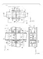
- the column beam connection structure concerning the embodiment is shown, (a) is a top view, (b) is a longitudinal section seen from the A1-A1 line of (a), (c) is the B1-B1 line of (a) It is the longitudinal cross-sectional view seen from.
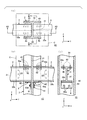
- the column beam connection structure which concerns on 2nd embodiment of this invention is shown, (a) is a top view, (b) is the longitudinal cross-sectional view seen from the A2-A2 line of (a), (c) is (a). It is the longitudinal cross-sectional view seen from the B2-B2 line.
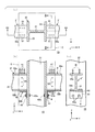
- the column beam connection structure which concerns on 3rd embodiment of this invention is shown, (a) is a top view, (b) is the longitudinal cross-sectional view seen from the A3-A3 line of (a), (c) is (a). It is the longitudinal cross-sectional view seen from the B3-B3 line.
- the column beam connection structure which concerns on 4th embodiment of this invention is shown, (a) is a top view, (b) is the longitudinal cross-sectional view seen from the A4-A4 line of (a), (c) is (a). It is the longitudinal cross-sectional view seen from the B4-B4 line.
- the present inventors have (a) a structure in which the seismic load is not borne at the joint between the steel column and the steel beam, the steel column and the steel beam are not rigidly joined by welding or the like, and (b) the steel beam Knowledge that it is possible to provide a column-to-beam connection structure and a steel-framed reinforced concrete column with excellent workability and safety by providing locking means to prevent the longitudinal displacement of the steel beam after placing concrete on the upper surface of the steel did.
- the strong axis direction X means a direction in which the cross-section secondary moment is maximum in a cross section perpendicular to the material axis direction Z of the column.
- the extending direction of the web in the cross section perpendicular to the material axis direction Z of the H-section steel is the strong axis direction.
- the weak axis direction Y means a direction in which the cross-section secondary moment is minimized in a cross section perpendicular to the material axis direction Z of the column.
- the extending direction of the flange in the cross section perpendicular to the material axis direction Z of the H-section steel is the weak axis direction.
- FIG. 1 shows a steel reinforced concrete column 10 (SRC structure) including a beam-column joint structure 1A according to a first embodiment of the present invention.
- a beam-to-column connection structure 1A includes a steel column 2 that is erected along a vertical direction Z, and a steel beam 3 that is disposed so that the end surface faces the side surface of the steel column 2. It is the structure for joining.
- the steel column 2 is made of an H-shaped steel having a web 21 and a pair of flanges 22.
- the steel beam 3 is made of an H-shaped steel having a web 31 and a pair of upper and lower upper flanges 32a and 32b, and is disposed so as to extend along the weak axis direction Y of the steel column 2. That is, the steel beam 3 is arranged so that the end surface faces the side portion of the web 21 of the steel column 2.
- a high strength steel material having a yield strength of 400 MPa or more, preferably 460 MPa or more can be used.
- a horizontal rebar insertion hole 33 is formed in the web 31 of the steel beam 3.
- a vertical reinforcing bar 5 a is arranged in parallel with the material axis direction of the steel column 2, and a horizontal reinforcing bar 5 b inserted through the horizontal reinforcing bar insertion hole 33 is assembled to the vertical reinforcing bar 5 a.
- concrete C is placed around the steel column 2 in a region indicated by a dotted line in FIG. 1 so as to embed the vertical reinforcing bar 5a and the horizontal reinforcing bar 5b.
- the periphery of the steel column 2 and the column beam joint structure 1A is covered with the reinforced concrete, and the steel reinforced concrete column 10 is constructed.
- the steel beam 3 ′ may be arranged on the side of the flange 22 of the steel column 2 according to the installation position of the steel reinforced concrete column 10.
- the steel reinforced concrete column 10 in this embodiment is a column having a substantially square cross section, but may be a column having a substantially rectangular cross section.
- FIGS. 2A and 2B show a column beam connection structure 1A according to the present embodiment, in which FIG. 2A is a plan view, FIG. 2B is a longitudinal sectional view taken along line A1-A1 in FIG. It is the longitudinal cross-sectional view seen from the B1-B1 line
- the beam placing members 6 are joined to both sides of the web 21 of the steel column 2.
- the beam mounting member 6 is configured by an angle (an angle steel) having a vertical surface 61 attached to the side surface of the web 21 of the steel column 2 and a horizontal surface 62 extending in the horizontal direction from the upper end of the vertical surface 61. .
- a bolt 63a is inserted into a hole penetrating the web 21 and the beam mounting member 6 provided on both side surfaces thereof and screwed into a nut 63b.
- a mounting member 6 is provided on the side surface of the steel column 2.
- the lower flange 32b of the steel beam 3 is placed on the upper surface of the horizontal surface 62 of the beam placing member 6 thus provided in a manner that is movable in the horizontal direction.
- the aspect that is movable in the horizontal direction means that the steel beam 3 is not fixed to the steel column 2 or the beam mounting member 6 by welding or bolts before the concrete C is hardened. It means an aspect that is slidable in the direction and the short direction.
- the size of the beam placing member 6 is not limited as long as it can support the load during construction until the concrete C to be placed is hardened. Since the construction load acting on the steel beam 3 is a vertically downward force, the steel beam 3 is basically required to be placed on the beam placing member 6. However, force (in the direction in which the steel beam 3 is pressed against the web 21 of the steel column 2) generated in the vicinity of the lower flange 32 b of the steel beam 3 for accurate positioning of the steel beam 3 or due to its own weight or the like ( In order to bear the arrow f1) in FIG. 2B, the steel beam 3 and the vertical surface 61 of the beam mounting member 6 may be temporarily fixed and joined with a supporting bolt or the like. For example, the steel beam 3 may be maintained in a state in which the steel beam 3 can be moved horizontally by inserting the support bolt into a bolt hole having play in the horizontal direction and fixing the support bolt without torque.
- a force in the direction away from the web 21 of the steel column 2 (arrow f ⁇ b> 2 in FIG. 2B) is generated by a bending moment acting on the steel beam 3.
- a plurality of studs 41 are installed on the upper surface of the upper flange 32a of the steel beam 3. Since the stud 41 is installed at a position where the concrete C is cast, the steel beam 3 is prevented from being displaced in the length direction by a shear reinforcement effect caused by being embedded in the concrete C of the steel reinforced concrete column 10. Can do.
- the steel beam 3 is prevented from shifting in the length direction, and the steel beam 3 is steel reinforced concrete. It is possible to prevent the pillar 10 from falling off.
- the stud 41 has a body portion 41a and an enlarged head portion 41b formed on the upper end side of the body portion 41a and having a diameter larger than that of the body portion 41a. It is preferable to have. When such a stud is used, a locking force in the vertical direction is also generated, so that the above-described drop-off prevention effect can be further enhanced.
- the stud 41 may be installed before placing the concrete C, and can be easily and quickly installed by using a stud welding gun or the like.
- the welding (rigid connection) between the web 21 of the steel column 2 and the end surface in the longitudinal direction of the steel beam 3 for resistance to seismic force as in the prior art. Is not done. Therefore, since the construction is easier than in the case of performing welding for seismic reinforcement, it is possible to construct the column beam connection structure 1A in a short construction period. Further, since it is not necessary to consider welding between the column and the beam, a high-strength steel material such as a steel material having a yield strength of 400 MPa or more, preferably 460 MPa or more can be used. Therefore, it is possible to reduce the weight and size of the steel material required for strength design.
- the steel beam 3 is placed on the upper surface of the beam placing member 6 in a manner that is movable in the horizontal direction, so that the steel beam can be easily aligned. This improves the workability.
- the vertical load acting on the steel beam 3 through the floor slab of the building or by the dead weight of the steel beam 3 is a portion embedded in the steel reinforced concrete column 10. It is transmitted to the concrete C placed on the column as a support pressure of the lower flange 32b of the steel beam 3. That is, the beam placing member 6 on which the steel beam 3 is placed may be any member that supports a load during construction until the concrete C is hardened.
- the stud 41 as the locking means prevents the displacement of the steel beam 3 in the length direction, the steel beam 3 is prevented from coming out of the steel reinforced concrete column 10. As a result, it is possible to easily and quickly construct the column beam connection structure 1A without performing complicated reinforcement as in the past.
- the steel column 2 and the steel beam 3 are not welded with a high joint strength such as a rigid joint capable of withstanding an earthquake load, a high-strength pole having a yield strength of 400 MPa or more, more preferably 460 MPa or more. Even H-shaped steels that are difficult to weld, such as thick H-shaped steels, can be easily used.
- a steel rolled H-section steel or a welded assembly H-shaped cross-section member can be used as the steel beam 3.
- the seismic isolation mechanism when providing a seismic isolation mechanism in an earthquake occurrence area, is provided other than the structural member of the building, not the column beam joint structure 1A, and the column beam joint structure 1A does not bear an earthquake load.
- the steel beam can be reliably bonded to the steel reinforced concrete column, and therefore the concrete floor slab and the steel reinforced concrete column may be structurally separated. That is, it is not necessary to fix the reinforcing bar of the concrete floor slab to the steel-framed reinforced concrete column, and the concrete floor slab and the steel-framed reinforced concrete column can be placed separately, and the construction becomes easy.
- the conventional beam-column joint structure proposed in Patent Documents 1 to 3 is intended to rigidly join a steel column and a steel beam constituting an SRC structure against an earthquake load.
- the seismic load acting on the structural member is reduced on the premise that the seismic load is borne by the seismic isolation mechanism other than the structural member of the building. Applicable to the case. Therefore, in the column beam connection structure 1A according to the present embodiment, a special structure for resisting an earthquake load as in the conventional case is not provided, and the steel beam is placed on the beam placement member attached to the steel column. In this state, the displacement preventing means in the steel beam is embedded in the concrete of the steel-framed reinforced concrete column. As a result, the vertical load due to the weight of the steel beam and the vertical load acting on the steel beam from the floor slab of the building can be supported, the column beam joint structure 1A can be rationalized, and the construction can be performed easily and quickly. .
- FIG. 3 shows a beam-column joint structure 1B according to the second embodiment of the present invention.
- the column beam connection structure 1B according to this embodiment is different from the column beam connection structure 1A according to the first embodiment described above in that a dowel through hole 42 is used as a locking means instead of the stud 41. That is, in the column beam joint structure 1B according to the present embodiment, as shown in FIGS. 3A, 3B and 3C, the concrete C of the steel reinforced concrete column 10 of the upper flange 32a of the steel beam 3 is provided.
- a plurality of dowel through-holes 42 penetrating the upper flange 32a in the thickness direction are formed as locking means in the portion embedded in.
- FIG. 4 shows a beam-column joint structure 1C according to the third embodiment of the present invention.
- the gibber rebar 43 is inserted into a plurality of dowel through holes 42 provided in the same manner as the beam-column joint structure 1B according to the second embodiment.
- the lower side is made to protrude from the upper surface and lower surface of the upper flange 32a.
- the shear reinforcement effect is produced by embedding the gibber reinforcing bar 43 in the concrete C of the steel reinforced concrete column 10, the displacement of the steel beam 3 in the length direction is prevented. Can do. Further, a part of the concrete C also enters the space between the inner peripheral surface of the dowel through hole 42 and the outer peripheral surface of the dowel reinforcing bar 43, that is, the space generated by the clearance between the dowel through hole 42 and the dowel reinforcing bar 43. This gives the Giber effect. Therefore, the combined effect of the shear reinforcement effect and the Gybel effect can strongly prevent the steel beam 3 from shifting in the length direction, and can more stably prevent the steel beam 3 from falling out of the steel reinforced concrete column 10.
- the column beam connection structure 1B according to the second embodiment in which the diver rebar 43 is not inserted since the gibber rebar 43 inserted in the through-hole 42 can increase the shear resistance of the placed concrete C, the column beam connection structure 1B according to the second embodiment in which the diver rebar 43 is not inserted.
- the number of the dowel through holes 42 can be reduced as compared with FIG. Therefore, even when the outer shape of the steel reinforced concrete column 10 is small and the embedding length of the steel beam 3 in the concrete C is small, the displacement of the steel beam 3 in the length direction can be prevented, and the steel beam 3 It is prevented that the steel frame reinforced concrete pillar 10 comes out.
- the ratio of the cross-sectional area S1 of the cross section perpendicular to the material axis direction of the gibber reinforcing bar 43 to the cross-sectional area S2 of the cross section perpendicular to the penetrating direction of the diver through-hole 42 is used.
- a value of S1 / S2 is preferably 0.2 or more and 0.6 or less. When the value of S1 / S2 is 0.2 or less, the reinforcing effect may not be obtained because the bevel rebar is too thin and the bending behavior is excellent.
- S1 / S2 when the value of S1 / S2 is 0.6 or more, the filling property of the concrete is deteriorated, and there is a case where a void is generated in the dowel hole due to poor construction.
- S1 / S2 is reduced, in order to prevent the gibber bar 43 from falling off, a gibber bar whose upper end is bent is used, or a substantially U-shaped gibber bar is used so as to straddle adjacent holes. It may be used.
- FIG. 5 shows a column beam joint structure 1D according to a fourth embodiment of the present invention.
- the column beam connection structure 1D according to the fourth embodiment is such that the steel beam 3 is bonded along the weak axis direction Y of the steel column 2 in that the steel beam 3 is bonded along the strong axis direction X of the steel column 2. It is different from the beam-column joint structure 1A according to the first embodiment that is joined.
- the beam mounting member 6 is opposed to the outer sides of both flanges 22 and 22 of the steel column 2. These are fixed by bolts 63a and nuts 63b.
- the stud 41 is used as the locking means in the same manner as the column beam joint structure 1A according to the first embodiment, but the column beam joint structure 1B according to the second embodiment or the third embodiment, Like 1C, it may be a dowel through hole 42 or a dowel rebar 43, or a combination thereof.
- the end surface of the steel beam 3 is disposed so as to face the side portion of the flange 22 spaced from the central axis of the steel column 2. Therefore, compared to the column beam joint structures 1A to 1C according to the first to third embodiments in which the end surface of the steel beam 3 is disposed so as to face the side portion of the web 21 of the steel column 2, the steel beam 3 embedded in steel reinforced concrete columns 10 tends to be small.
- the steel reinforced concrete column 10 has a substantially square cross section as in the column beam connection structures 1A to 1D according to the first embodiment to the fourth embodiment, the steel reinforced concrete column is long in the length direction of the steel beam.
- the embedding length of the steel beam 3 in the steel reinforced concrete column 10 tends to be small.
- the stud 41, the dowel through-hole 42, the dowel rebar 43, etc. described above are used as the locking means, it is possible to sufficiently prevent the steel beam 3 from shifting in the length direction. The falling off from the reinforced concrete pillar 10 can be prevented.
- H-section steel is used as the steel column, but square steel or I-section steel may be used instead of H-section steel.
- H-section steel is used as the steel beam, but square steel or I-section steel may be used instead of H-section steel.
- 2nd embodiment and 3rd embodiment illustrated the case where the shape of the cross section perpendicular
- an angle is used as the beam placing member, but any member that can be placed on the side of the steel column and can place the steel beam on the upper surface may be used.
- Square steel may be used.
- the side of the steel column and the end of the steel beam are arranged in surface contact (not joined by welding or bolting).
- the clearance gap may be formed to such an extent that it does not contact a surface.
- the first to fourth embodiments described above may be appropriately combined. For example, studs and dowel through holes may be alternately arranged.
Landscapes
- Engineering & Computer Science (AREA)
- Architecture (AREA)
- Physics & Mathematics (AREA)
- Electromagnetism (AREA)
- Civil Engineering (AREA)
- Structural Engineering (AREA)
- Joining Of Building Structures In Genera (AREA)
Abstract
Description
本願は、2016年3月31日に、日本に出願された特願2016-071540号に基づき優先権を主張し、その内容をここに援用する。
ところが、特許文献1に開示された発明は、地震力に対して柱梁接合部を剛接合にするための技術であり、鉄骨造の梁の上下フランジの両方を鉄骨造の柱のフランジに溶接している。
ところが、特許文献2に開示された発明もまた、地震力に対して柱梁接合部を剛接合にするための技術であり、柱鉄骨の弱軸方向に鉄骨梁を剛接合する技術である。そして、柱鉄骨の弱軸方向は、SRC造の柱の断面形状を大きくすることで鉄骨梁の埋め込み長さを大きくしている。
ところが、特許文献3に開示された発明も、地震力に対して二方向の柱梁接合部を剛接合にするための技術であり、SRC造の柱を長方形にして外周梁の埋め込み長さを確保している。
ところが、前記特許文献1~3に開示された発明はいずれも、地震荷重を想定した補強を要する接合構造であり、梁に作用する鉛直方向の荷重を支持することに特化した構造ではない。特に、柱と梁との接合部に溶接を施すことにより地震荷重を負担しようとする場合には、柱や梁に高強度の鋼材を用いると溶接作業が困難となるため高強度の鉄骨柱や鉄骨梁を用いることができなくなるという問題もあった。
(2)上記(1)に記載の柱梁接合構造では、前記係止手段が前記スタッドであり、前記スタッドの上端側に、拡径頭部が形成されてもよい。
(3)上記(1)に記載の柱梁接合構造では、前記係止手段が前記ジベル貫通孔であり、前記ジベル貫通孔に挿通されるジベル鉄筋を更に備えてもよい。
(4)上記(3)に記載の柱梁接合構造では、前記ジベル鉄筋の材軸方向に垂直な断面の断面積S1と、前記ジベル貫通孔の貫通方向に垂直な断面の断面積S2との比率S1/S2が0.5以上0.8以下であってもよい。
(5)上記(1)~(4)のいずれか一項に記載の柱梁接合構造では、前記鉄骨柱の降伏強さが400MPa以上であってもよい。
(6)上記(1)~(5)のいずれか一項に記載の柱梁接合構造では、前記鉄骨柱がH形鋼であり、前記鉄骨梁の端面が前記H形鋼のウェブに対向して設けられてもよい。
(7)上記(1)~(6)のいずれか一項に記載の柱梁接合構造では、前記梁載置部材が、前記鉄骨柱の前記側部に取り付けられる垂直面と、前記垂直部の上端から水平方向に延在する水平面と、を備えるアングルであってもよい。
(8)上記(1)~(7)のいずれか一項に記載の柱梁接合構造では、前記鉄骨梁の端面が前記鉄骨柱の前記側部に固定されていなくてもよい。
(9)上記(1)~(8)のいずれか一項に記載の柱梁接合構造では、前記鉄骨梁と前記鉄骨柱とが溶接により接合されていなくてもよい。
(10)本発明の第二の態様は、上記(1)~(9)のいずれか一項に記載の柱梁接合構造と、前記柱梁接合構造の周囲に打設される鉄筋コンクリートと、を備える鉄骨鉄筋コンクリート柱である。
特に、鉄骨柱と鉄骨梁との溶接が省略されるため、溶接施工が困難な高強度の柱部材を用いることができる。従って、安全性の高い柱梁接合構造及び鉄骨鉄筋コンクリート柱を得ることができる。
更には、鉄骨梁の上面には、スタッドとジベル貫通孔の少なくとも一方が係止手段として設けられるため、コンクリートが打設されて硬化した後に、鉄骨梁が鉄骨梁の長さ方向に移動することが抑制される。従って、鉄骨梁が鉄骨鉄筋コンクリート柱から抜け落ちることを防止できるため、高い安全性を確保することができる。
従って、高い施工性と安全性とを兼ね揃えた柱梁接合構造及び鉄骨鉄筋コンクリート柱を提供することが可能である。
なお、本明細書および図面において、実質的に同一の機能構成を有する要素においては、同一の符号を付することにより重複説明を省略する。
また、本明細書における用語を以下に説明する。
強軸方向Xとは、柱の材軸方向Zに垂直な断面において、断面二次モーメントが最大となる方向を意味する。柱がH形鋼である場合、H形鋼の材軸方向Zに垂直な断面におけるウェブの延在方向が強軸方向である。
弱軸方向Yとは、柱の材軸方向Zに垂直な断面において、断面二次モーメントが最小となる方向を意味する。柱がH形鋼である場合、H形鋼の材軸方向Zに垂直な断面におけるフランジの延在方向が弱軸方向である。
図1は、本発明の第一実施形態に係る柱梁接合構造1Aを含む鉄骨鉄筋コンクリート柱10(SRC構造)を示す。
図1に示すように、柱梁接合構造1Aは、鉛直方向Zに沿って立設される鉄骨柱2と、鉄骨柱2の側面に対して端面が対向するように配置される鉄骨梁3とを接合するための構造である。
鉄骨梁3は、ウェブ31と上下一対の上フランジ32a、下フランジ32bとを有するH形鋼から構成され、鉄骨柱2の弱軸方向Yに沿って延在するように配置される。すなわち、鉄骨柱2のウェブ21の側部に対して端面が対向するように、鉄骨梁3が配置されている。
柱と梁とを接合するための溶接を行う従来技術においては、溶接性を考慮し、高強度の鋼材を用いることに材料設計上の制限があった。しかし、本実施形態に係る柱梁接合構造1Aでは、柱と梁とを接合するための溶接が行われない。従って、例えば降伏強さが400MPa以上、好ましくは460MPa以上の高強度の鋼材を用いることができる。
図1に示すように、鉄骨鉄筋コンクリート柱10の設置位置に応じて、鉄骨柱2のフランジ22の側部に対しても、鉄骨梁3’が配置されてもよい。
図2の(b)、(c)に示すように、鉄骨柱2のウェブ21の両側部に、梁載置部材6が接合されている。
この梁載置部材6は、鉄骨柱2のウェブ21の側面に取り付けられる垂直面61と、垂直面61の上端から水平方向に延在する水平面62とを有するアングル(山形鋼)により構成される。
本実施形態に係る柱梁接合構造1Aでは、ウェブ21と、その両側面に設けられた梁載置部材6とを貫通する孔にボルト63aを挿通してナット63bに螺合することで、梁載置部材6が鉄骨柱2の側面に設けられている。
そして、このようにして設けられた梁載置部材6の水平面62の上面に、鉄骨梁3の下フランジ32bが水平方向に移動自在な態様で載置される。
ここで、水平方向に移動自在な態様とは、鉄骨梁3が、コンクリートCが硬化する前の状態において、鉄骨柱2又は梁載置部材6に溶接やボルトなどで固定されておらず、長手方向と短手方向に摺動可能とされている態様を意味する。
スタッド41は、コンクリートCが打設される位置に設置されるため、鉄骨鉄筋コンクリート柱10のコンクリートC内に埋め込まれることで生じるせん断補強効果により、鉄骨梁3の長さ方向の位置ずれを防ぐことができる。従って、鉄骨鉄筋コンクリート柱10の外形が小さくて鉄骨梁3の鉄骨鉄筋コンクリート柱10への埋め込み長さが短い場合であっても、鉄骨梁3の長さ方向のずれを防ぎ、鉄骨梁3が鉄骨鉄筋コンクリート柱10から抜け落ちることを防止することができる。
更に、本実施形態に係る柱梁接合構造1Aでは、鉄骨梁3が水平方向に移動自在な態様で梁載置部材6の上面に載置されるため、鉄骨梁の位置合わせを容易に行うことが可能となり、施工性が向上する。
すなわち、鉄骨梁3が載置されている梁載置部材6は、コンクリートCが硬化するまでの建設時荷重を支えるものであればよい。
一方で、係止手段であるスタッド41が鉄骨梁3の長さ方向の位置ずれを防ぐため、鉄骨梁3が鉄骨鉄筋コンクリート柱10から抜け出すことが防止される。
この結果、従来のように複雑な補強を行うことなく、柱梁接合構造1Aの構築を容易且つ迅速に行うことができる。
鉄骨柱2と鉄骨梁3とは、地震荷重に耐えうる剛接合のような高い接合強度の溶接を行わないことから、降伏強さが400MPa以上、更には460MPa以上であるような高強度の極厚H形鋼など、溶接施工が困難なH形鋼等であっても容易に用いることができる。
なお、鉄骨梁3としては、鋼製の圧延H形鋼または溶接組立H形断面部材を用いることができる。
図3は、本発明の第二実施形態に係る柱梁接合構造1Bを示す。
この実施形態に係る柱梁接合構造1Bは、スタッド41の替わりにジベル貫通孔42が係止手段として用いられている点で、上述の第一実施形態に係る柱梁接合構造1Aと異なる。
すなわち、本実施形態に係る柱梁接合構造1Bでは、図3の(a)、(b)、(c)に示されるように、鉄骨梁3の上フランジ32aの、鉄骨鉄筋コンクリート柱10のコンクリートCに埋め込まれる部分に、上フランジ32aを厚さ方向に貫通する複数のジベル貫通孔42が係止手段として形成されている。
図4は、本発明の第三実施形態に係る柱梁接合構造1Cを示す。
この実施形態に係る柱梁接合構造1Cでは、第二実施形態に係る柱梁接合構造1Bと同様に設けられた複数のジベル貫通孔42にジベル鉄筋43が挿通され、そのジベル鉄筋43の上方側及び下方側を上フランジ32aの上面及び下面から突出させている。
したがって、鉄骨鉄筋コンクリート柱10の外形が小さくて鉄骨梁3のコンクリートCへの埋め込み長さが小さい場合であっても、鉄骨梁3の長さ方向の位置ずれを防ぐことができ、鉄骨梁3が鉄骨鉄筋コンクリート柱10から抜け出すことが防止される。
尚、S1/S2を小さくする場合、ジベル鉄筋43の抜け落ちを防止するために、その上端側を屈曲させたジベル鉄筋を用いたり、隣り合う孔に跨るように略U字型としたジベル鉄筋を用いてもよい。
図5は、本発明の第四実施形態に係る柱梁接合構造1Dを示す。
第四実施形態に係る柱梁接合構造1Dは、鉄骨柱2の強軸方向Xに沿って鉄骨梁3が接合されている点で、鉄骨柱2の弱軸方向Yに沿って鉄骨梁3が接合されている第一実施形態に係る柱梁接合構造1Aと異なる。
図5に示す例では、係止手段として第一実施形態に係る柱梁接合構造1Aと同様にスタッド41を用いているが、第二実施形態や第三実施形態に係る柱梁接合構造1B、1Cと同様にジベル貫通孔42やジベル鉄筋43であってもよく、それらの組合せであってもよい。
特に、第一実施形態~第四実施形態に係る柱梁接合構造1A~1Dのように、鉄骨鉄筋コンクリート柱10が断面略正方形である場合には、鉄骨鉄筋コンクリート柱が鉄骨梁の長さ方向に長い断面略矩形状の場合に比べて、鉄骨梁3の鉄骨鉄筋コンクリート柱10への埋め込み長さが小さくなりやすい。
しかしながら、係止手段として、前述したスタッド41、ジベル貫通孔42、ジベル鉄筋43などを用いることで、鉄骨梁3の長さ方向のずれ止めを十分に防ぐことができるため、鉄骨梁3の鉄骨鉄筋コンクリート柱10からの抜け落ちを防止することができる。
また、上述の第一実施形態~第四実施形態では、鉄骨梁としてH形鋼を使用しているが、H形鋼に替えて角形鋼やI形鋼を使用してもよい。
また、上述の第二実施形態、第三実施形態では、ジベル貫通孔42の貫通方向に垂直な断面の形状が円形である場合を例示しているが、楕円形や多角形であってもよい。
また、上述の第一実施形態~第四実施形態では、梁載置部材としてアングルを用いているが、鉄骨柱の側部に設置できて鉄骨梁を上面に載置できる部材であればよく、角形鋼を用いてもよい。
また、上述の第一実施形態~第四実施形態では、鉄骨柱の側部と鉄骨梁の端部とが面接触(溶接やボルト締めなどによる接合はされていない)した状態で配置されているが、面接触しない程度に隙間が形成されていてもよい。
上述の第一実施形態~第四実施形態を適宜組み合わせてもよく、例えば、スタッドとジベル貫通孔とを交互に配置させてもよい。
10 鉄骨鉄筋コンクリート柱
2 鉄骨柱(H形鋼)
21 ウェブ
22 フランジ
3、3’ 鉄骨梁(H形鋼)
31 ウェブ
32a 上フランジ
32b 下フランジ
33 水平鉄筋挿通孔
41 スタッド41a 胴体部
41b 頭部
42 ジベル貫通孔
43 ジベル鉄筋
5a 垂直鉄筋
5b 水平鉄筋
6 梁載置部材(アングル)
61 垂直面
62 水平面
63a ボルト
63b ナット
C コンクリート
X 強軸方向
Y 弱軸方向
Z 鉛直方向
Claims (10)
- 周囲にコンクリートが打設される鉄骨柱と、前記鉄骨柱の側方に配置される鉄骨梁との柱梁接合構造であって、
前記鉄骨柱の側部に設けられるとともに、前記鉄骨梁を水平方向に移動自在に支持する梁載置部材と;
前記鉄骨梁の上面に配置され、前記コンクリートに係止する係止手段と;
を備え、
前記係止手段が、前記鉄骨梁の前記上面に立設されるスタッド、及び、前記鉄骨梁の前記上面に形成されるジベル貫通孔の一方又は両方である
ことを特徴とする柱梁接合構造。 - 前記係止手段が前記スタッドであり、
前記スタッドの上端側に、拡径頭部が形成されている
ことを特徴とする、請求項1に記載の柱梁接合構造。 - 前記係止手段が前記ジベル貫通孔であり、
前記ジベル貫通孔に挿通されるジベル鉄筋を更に備える
ことを特徴とする、請求項1に記載の柱梁接合構造。 - 前記ジベル鉄筋の材軸方向に垂直な断面の断面積S1と、前記ジベル貫通孔の貫通方向に垂直な断面の断面積S2との比率S1/S2が0.5以上0.8以下である
ことを特徴とする請求項3に記載の柱梁接合構造。 - 前記鉄骨柱の降伏強さが400MPa以上である
ことを特徴とする請求項1~4のいずれか一項に記載の柱梁接合構造。 - 前記鉄骨柱がH形鋼であり、前記鉄骨梁の端面が前記H形鋼のウェブに対向して設けられる
ことを特徴とする請求項1~5のいずれか一項に記載の柱梁接合構造。 - 前記梁載置部材が、前記鉄骨柱の前記側部に取り付けられる垂直面と、前記垂直部の上端から水平方向に延在する水平面と、を備えるアングルである
ことを特徴とする請求項1~6のいずれか一項に記載の柱梁接合構造。 - 前記鉄骨梁の端面が前記鉄骨柱の前記側部に固定されていない
ことを特徴とする請求項1~7のいずれか一項に記載の柱梁接合構造。 - 前記鉄骨梁と前記鉄骨柱とが溶接により接合されていない
ことを特徴とする、請求項1~8のいずれか一項に記載の柱梁接合構造。 - 請求項1~9のいずれか一項に記載の柱梁接合構造と、
前記柱梁接合構造の周囲に打設される鉄筋コンクリートと、
を備えることを特徴とする鉄骨鉄筋コンクリート柱。
Priority Applications (2)
| Application Number | Priority Date | Filing Date | Title |
|---|---|---|---|
| SG11201806986QA SG11201806986QA (en) | 2016-03-31 | 2017-03-29 | Beam to column connection and steel reinforced concrete column |
| JP2018509360A JP6447777B2 (ja) | 2016-03-31 | 2017-03-29 | 柱梁接合構造及び鉄骨鉄筋コンクリート柱 |
Applications Claiming Priority (2)
| Application Number | Priority Date | Filing Date | Title |
|---|---|---|---|
| JP2016071540 | 2016-03-31 | ||
| JP2016-071540 | 2016-03-31 |
Publications (1)
| Publication Number | Publication Date |
|---|---|
| WO2017170732A1 true WO2017170732A1 (ja) | 2017-10-05 |
Family
ID=59964653
Family Applications (1)
| Application Number | Title | Priority Date | Filing Date |
|---|---|---|---|
| PCT/JP2017/012991 Ceased WO2017170732A1 (ja) | 2016-03-31 | 2017-03-29 | 柱梁接合構造及び鉄骨鉄筋コンクリート柱 |
Country Status (4)
| Country | Link |
|---|---|
| JP (1) | JP6447777B2 (ja) |
| SG (1) | SG11201806986QA (ja) |
| TW (1) | TWI651453B (ja) |
| WO (1) | WO2017170732A1 (ja) |
Cited By (2)
| Publication number | Priority date | Publication date | Assignee | Title |
|---|---|---|---|---|
| US11661742B2 (en) * | 2016-10-14 | 2023-05-30 | Arcelormittal | Steel reinforced concrete column |
| JP2023094933A (ja) * | 2021-12-24 | 2023-07-06 | 日本製鉄株式会社 | 柱梁接合構造および柱梁接合構造の製造方法 |
Families Citing this family (2)
| Publication number | Priority date | Publication date | Assignee | Title |
|---|---|---|---|---|
| CN113062448A (zh) * | 2021-03-31 | 2021-07-02 | 潮峰钢构集团有限公司 | 型钢柱与混凝土的框架梁钢筋连接系统及浇灌施工方法 |
| TWI769969B (zh) * | 2022-02-08 | 2022-07-01 | 財團法人國家實驗研究院 | 鋼骨外包覆混凝土型梁構件的鋼梁接合結構 |
Citations (2)
| Publication number | Priority date | Publication date | Assignee | Title |
|---|---|---|---|---|
| JPH10299170A (ja) * | 1997-04-21 | 1998-11-10 | Taisei Corp | 柱梁の接続構造 |
| JP5818363B2 (ja) * | 2012-06-05 | 2015-11-18 | 鹿島建設株式会社 | 柱・梁接合部における梁部材用保持部材及び梁部材用保持装置 |
Family Cites Families (2)
| Publication number | Priority date | Publication date | Assignee | Title |
|---|---|---|---|---|
| TW517741U (en) * | 2002-03-08 | 2003-01-11 | Runhorn Pretech Eng Co Ltd | Joint structure used in connecting reinforced concrete beam and column |
| TWI220017B (en) * | 2003-11-07 | 2004-08-01 | Neng-Yi Tu | A steel connection member |
-
2017
- 2017-03-29 JP JP2018509360A patent/JP6447777B2/ja not_active Expired - Fee Related
- 2017-03-29 WO PCT/JP2017/012991 patent/WO2017170732A1/ja not_active Ceased
- 2017-03-29 SG SG11201806986QA patent/SG11201806986QA/en unknown
- 2017-03-29 TW TW106110464A patent/TWI651453B/zh not_active IP Right Cessation
Patent Citations (2)
| Publication number | Priority date | Publication date | Assignee | Title |
|---|---|---|---|---|
| JPH10299170A (ja) * | 1997-04-21 | 1998-11-10 | Taisei Corp | 柱梁の接続構造 |
| JP5818363B2 (ja) * | 2012-06-05 | 2015-11-18 | 鹿島建設株式会社 | 柱・梁接合部における梁部材用保持部材及び梁部材用保持装置 |
Cited By (3)
| Publication number | Priority date | Publication date | Assignee | Title |
|---|---|---|---|---|
| US11661742B2 (en) * | 2016-10-14 | 2023-05-30 | Arcelormittal | Steel reinforced concrete column |
| JP2023094933A (ja) * | 2021-12-24 | 2023-07-06 | 日本製鉄株式会社 | 柱梁接合構造および柱梁接合構造の製造方法 |
| JP7678325B2 (ja) | 2021-12-24 | 2025-05-16 | 日本製鉄株式会社 | 柱梁接合構造および柱梁接合構造の製造方法 |
Also Published As
| Publication number | Publication date |
|---|---|
| SG11201806986QA (en) | 2018-09-27 |
| JP6447777B2 (ja) | 2019-01-09 |
| TW201739994A (zh) | 2017-11-16 |
| JPWO2017170732A1 (ja) | 2019-01-10 |
| TWI651453B (zh) | 2019-02-21 |
Similar Documents
| Publication | Publication Date | Title |
|---|---|---|
| JP4414834B2 (ja) | 耐震壁の構築方法 | |
| KR20110061841A (ko) | 콘크리트 충전 강관기둥과 에이치형강 보의 접합부 구조 및 시공방법 | |
| JP6447777B2 (ja) | 柱梁接合構造及び鉄骨鉄筋コンクリート柱 | |
| JP2007277952A (ja) | 耐震用接合構造及びその構築方法 | |
| JP2018009410A (ja) | 柱梁接合構造 | |
| JP7228344B2 (ja) | 鉄筋コンクリート造の躯体とブレースとの接合構造及びプレキャスト部材 | |
| JP6013028B2 (ja) | 外殻構造 | |
| JP2006188864A (ja) | 柱と梁の接合構造 | |
| KR101299574B1 (ko) | 사각 패널존을 이용한 모멘트 접합구조 | |
| KR101254983B1 (ko) | 콘크리트 충전강관과 보의 접합구조 | |
| JP5429812B2 (ja) | 軸部材とrc部材との接合構造及び方法 | |
| JP5654060B2 (ja) | ダンパーブレース及び制震構造 | |
| JP7155488B2 (ja) | 構造物耐震補強構造 | |
| JP4819605B2 (ja) | 端部と中央部とで強度の異なる緊張材を用いたプレキャストプレストレストコンクリート梁 | |
| JP2016089549A (ja) | 鉄筋コンクリート梁と鉄骨の柱又は鉄骨を備える柱との接合構造及び方法 | |
| JP6401960B2 (ja) | 間柱付き梁構造 | |
| JP4696843B2 (ja) | 合成梁構造 | |
| JP3215633U (ja) | ブレース取付構造 | |
| KR20180087701A (ko) | 내진보강 cft 기둥 및 이를 이용한 기존 건축물의 내진보강 공법 | |
| JP7137978B2 (ja) | 柱用板状部材 | |
| JP5490551B2 (ja) | システム建築用の柱梁接合部 | |
| JP2009108591A (ja) | 構造部材 | |
| JP6886830B2 (ja) | 座屈拘束ブレース、柱梁接続部の補強構造、及び建物 | |
| JP7211915B2 (ja) | 耐震補強構造 | |
| JP6180168B2 (ja) | 耐力壁の接合構造及び接合金物 |
Legal Events
| Date | Code | Title | Description |
|---|---|---|---|
| WWE | Wipo information: entry into national phase |
Ref document number: 11201806986Q Country of ref document: SG |
|
| WWE | Wipo information: entry into national phase |
Ref document number: 2018509360 Country of ref document: JP |
|
| NENP | Non-entry into the national phase |
Ref country code: DE |
|
| 121 | Ep: the epo has been informed by wipo that ep was designated in this application |
Ref document number: 17775266 Country of ref document: EP Kind code of ref document: A1 |
|
| 122 | Ep: pct application non-entry in european phase |
Ref document number: 17775266 Country of ref document: EP Kind code of ref document: A1 |