WO2017170665A1 - 金属ベルトの製造方法および金属ベルト - Google Patents
金属ベルトの製造方法および金属ベルト Download PDFInfo
- Publication number
- WO2017170665A1 WO2017170665A1 PCT/JP2017/012860 JP2017012860W WO2017170665A1 WO 2017170665 A1 WO2017170665 A1 WO 2017170665A1 JP 2017012860 W JP2017012860 W JP 2017012860W WO 2017170665 A1 WO2017170665 A1 WO 2017170665A1
- Authority
- WO
- WIPO (PCT)
- Prior art keywords
- ring
- end portion
- metal belt
- retaining member
- peripheral surface
- Prior art date
- Legal status (The legal status is an assumption and is not a legal conclusion. Google has not performed a legal analysis and makes no representation as to the accuracy of the status listed.)
- Ceased
Links
Images





Classifications
-
- F—MECHANICAL ENGINEERING; LIGHTING; HEATING; WEAPONS; BLASTING
- F16—ENGINEERING ELEMENTS AND UNITS; GENERAL MEASURES FOR PRODUCING AND MAINTAINING EFFECTIVE FUNCTIONING OF MACHINES OR INSTALLATIONS; THERMAL INSULATION IN GENERAL
- F16G—BELTS, CABLES, OR ROPES, PREDOMINANTLY USED FOR DRIVING PURPOSES; CHAINS; FITTINGS PREDOMINANTLY USED THEREFOR
- F16G5/00—V-belts, i.e. belts of tapered cross-section
- F16G5/16—V-belts, i.e. belts of tapered cross-section consisting of several parts
Definitions
- the present invention relates to a metal belt manufacturing method and a metal belt.
- a metal belt having an endless annular ring and a plurality of elements arranged circumferentially along the ring is known.
- Such a metal belt is disclosed in, for example, Japanese Patent Application Laid-Open No. 2001-193996.
- Japanese Patent Application Laid-Open No. 2001-193996 discloses a metal belt that transmits power of a driving pulley to a driven pulley by being applied to the driving pulley and a driven (driven) pulley.
- This metal belt is made of an endless ring-shaped metal band (ring), a plurality of metal elements including a recess for holding the band, and an endless band-shaped metal for preventing the band from being detached from the recess of the element.
- a drop-off prevention body prevention member. Note that, as a cross-sectional structure of the metal belt, the width of the drop-off prevention body is larger than the width of the band.
- the fall prevention body covers the outer peripheral surface of the band while the band is mounted in the concave portion of the element, and both edges are locked to the flange portion of the concave portion, so that the band is not detached from the concave portion.
- the dropout prevention body is formed with a long hole penetrating in the thickness direction and extending a predetermined distance in the longitudinal direction. Therefore, in the manufacturing process of the metal belt, the drop-off prevention body is placed along the outer peripheral surface of the band (ring) and the width of the drop-off prevention body in the section provided with the long hole is locally narrowed. Is inserted into the narrow part of the band and the fall-off prevention body.
- the width of the drop prevention body is restored to the original size in the recess so that both edges of the fall prevention body are engaged with the flange portion of the recess. It is configured to be stopped.
- the present invention has been made to solve the above-described problems, and one object of the present invention is to provide a metal belt manufacturing method capable of shortening the assembly work time and the metal belt. It is to be.
- a metal belt manufacturing method is a recess that holds an endless annular ring by a base, a flange, and a connecting portion that connects the base and the flange.
- the metal belt elements that are constructed of are fitted into the ring in sequence and arranged along the ring, and the multiple elements are arranged in the ring to prevent the ring from detaching from the recess of the element Inserting the end strip-shaped retaining member into the gap between the outer peripheral surface of the ring and the inner surface facing the base of the flange in the recess, and arranging the end strip in a circumferential manner along the outer peripheral surface of the ring; Connecting the start end portion and the end end portion of the retaining member.
- an end-strip-shaped retaining member that prevents the ring from separating from the recess of the element in a state where the plurality of elements are arranged in the ring. Is inserted into the gap between the outer peripheral surface of the ring and the inner surface of the recess facing the base portion of the flange, and is disposed circumferentially along the outer peripheral surface of the ring, and the start end and the end of the endless strip-shaped retaining member And a step of connecting the parts.
- the end-band-shaped retaining member is inserted into the gap between the outer peripheral surface of the ring and the inner surface facing the base portion of the flange portion in the recess to make it circumferential
- the metal belt can be completed by connecting the start and end portions of the retaining member. Therefore, since most elements constituting one metal belt can be assembled to the ring side in a short time, the assembling work time for manufacturing the metal belt can be shortened. Moreover, since one metal belt can be manufactured in a shorter time, the manufacturing method of the metal belt which can improve production efficiency can be provided.
- a metal belt according to a second aspect of the present invention includes an endless annular ring, a plurality of elements each including a recess that holds the ring, and an outer peripheral surface of the ring in a state where the plurality of elements are arranged in the ring.
- a circumferential end, and a start end portion and a terminal end portion are connected to each other, and an end band-shaped retaining member that prevents the ring from being detached from the concave portion of the element.
- a plurality of elements are arranged circumferentially along the outer peripheral surface of the ring in a state where the plurality of elements are arranged in the ring, and the start end portion and the end end portion are provided.
- An end strip-shaped retaining member that is connected to each other and prevents the ring from detaching from the recess of the element is provided.
- the end band-shaped retaining member is placed in the gap between the outer peripheral surface of the ring and the inner surface of the recess (the inner surface facing the base of the flange in the recess)
- the metal belt can be completed by connecting the start and end portions of the retaining member. Therefore, since most elements constituting one metal belt can be assembled to the ring side in a short time, the assembling work time for manufacturing the metal belt can be shortened. Moreover, since one metal belt can be manufactured in a shorter time, a metal belt capable of improving production efficiency can be provided.
- FIG. 2 is a cross-sectional view of the metal belt shown in FIG. 1 taken along line 150-150.
- FIG. 2 is a cross-sectional view taken along the line 160-160 of the metal belt shown in FIG. It is an expanded view of the retainer which comprises the metal belt manufactured using the manufacturing method by 1st Embodiment of this invention.
- It is the figure which showed the detailed structure of the metal belt manufactured using the manufacturing method by 1st Embodiment of this invention.
- the metal belt 100 manufactured using the manufacturing method according to the first embodiment of the present invention includes a ring 10, a plurality of elements 20, and a retainer 30.
- the metal belt 100 includes a driving side (input shaft) pulley (not shown) and a driven side (output shaft) pulley (not shown) in a belt type continuously variable transmission (CVT) mounted on a vehicle (not shown).
- CVT continuously variable transmission
- mechanical element parts that play a role of transmitting power between the pulleys.
- the elements 20 in some sections are indicated by broken lines, and the structure of the ring 10 incorporated therein and the connecting structure of a retainer 30 described later are indicated by solid lines.
- the ring 10 includes a plurality of endless annular metal thin plates 10a laminated in the plate thickness direction (Z-axis direction).
- the element 20 is made of metal, and each element 20 has a recess 25 for holding (accommodating) the ring 10 having a multilayer shape on the outer peripheral side (the outer side in the rotational radius direction of the metal belt 100).
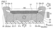
- the element 20 includes a base 21 having a bottom 22 that holds the ring 10 in the recess 25, and a pair of flanges 23 that prevent the retainer 30 from being detached from the recess 25 in a state where the ring 10 and the retainer 30 are assembled.
- the base portion 21 and the flange portion 23 are connected to each other.
- the bottom portion 22, the connecting portion 24, and the flange portion 23 constitute a concave inner surface 25 a in the concave portion 25.
- the retainer 30 is sandwiched in a gap S between the outer peripheral surface 12 of the ring 10 (the outermost thin metal plate 10a) and the lower surface 23a (arrow Z2 side) of the pair of flanges 23 of the concave inner surface 25a. ing.
- the retainer 30 is arranged in a circumferential shape (track shape) along the outer peripheral surface 12 on the outer side in the rotational radius direction of the ring 10.
- the lower surface 23a is an example of the “inner surface facing the base portion of the flange portion in the recess” in the claims.
- the pair of outer side surfaces 26 from the connecting portion 24 to the flange portion 23 are fitted into the respective V-shaped grooves (sliding surfaces) of the driving pulley and the driven pulley (not shown) to make surface contact. It is a part to do.
- the retainer 30 is made of metal (made of maraging steel) and has a role of preventing the ring 10 from being detached from the concave portion 25 of the element 20 to the outside in the rotational radius direction of the metal belt 100.
- the retainer 30 is an example of the “end strip-shaped retaining member” in the claims.
- the retainer 30 is formed in the shape of an end band due to the manufacturing process of the metal belt 100. That is, the retainer 30 has a first end portion 31, the other end portion 32, and a main body portion 33 that connects the one end portion 31 and the other end portion 32 in a single state.
- the end 31 is bifurcated (symmetric) in the width direction (Y-axis direction) with a center line (not shown) along the X-axis direction of the main body 33 as a symmetry axis, and in the X-axis direction. It has a pair of front-end
- a notch 31c cut out in a U-shape is provided at a portion where the tip end 31a on the Y2 side and the tip end 31b on the Y1 side face each other in the width direction.
- Each of the tip portions 31a and 31b is formed with a hole portion 31d penetrating in the thickness direction (Z-axis direction).
- the other end 32 has a single tip 32 a that extends along a center line (not shown) of the main body 33 and has a width W ⁇ b> 2 smaller than the main body 33. Note that the width W2 of the tip end portion 32a is slightly smaller than the width W1 of the cutout portion 31c at the one end portion 31.
- the main body 33 has a constant width W ⁇ b> 3 from the boundary portion with the one end portion 31 to the boundary portion with the other end portion 32.
- the one end portion 31 and the other end portion 32 are examples of the “start end portion” and the “end end portion” in the claims, respectively.
- a plurality of elements 20 are circumferentially arranged along the inner peripheral surface 11 of the ring 10 (the innermost metal thin plate 10a) (see FIG. 5). 1), the one end portion 31 and the other end portion 32 of the retainer 30 are connected (welded) to each other with the plate-like member 35 interposed therebetween.
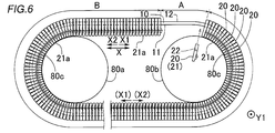
- the endless annular ring 10 is hung between a pair of shape holding rollers 80a and 80b, and the shape holding rollers 80a and 80b are separated from each other by a predetermined distance in the X-axis direction. 10 is formed in a track shape (oval shape). Then, a plurality of elements 20 are arranged on the track-shaped ring 10. Specifically, the concave portion 25 of the element 20 is fitted into the inner peripheral surface 11 of the ring 10 from the inner side (the inner peripheral surface 11 side) of the ring 10.
- the elements 20 are arranged in most other sections B with the section A in which the plurality of elements 20 are not arranged remaining.
- the plurality of elements 20 are arranged (aligned) so that the base 21 of the elements 20 is located on the inner side in the rotational radius direction.
- the lower surface 21a contacts the outer surfaces 80c of the shape maintaining rollers 80a and 80b.
- the ring 10 is disposed (accommodated) in the recess 25 of the element 20.
- a gap S is formed between both end portions of the outer peripheral surface 12 of the ring 10 in the width direction (Y-axis direction) and the lower surface 23 a of the recess 25 facing the base portion 21 of the flange portion 23. Further, the gap S extends continuously over the section B along the direction (X-axis direction) in which the elements 20 are arranged.
- the section A is an example of the “partial section” in the claims.
- the leading end portions 31a and 31b formed on the one end portion 31 of the retainer 30 formed in a strip shape (elongated shape) are brought close to each other, thereby reducing the width W of the one end portion 31. It is done.
- an assembly operator (not shown) connects the pair of end portions 90a and 90b of the hook member 90 formed in a U shape in advance to the pair of holes 31d formed in the tip portions 31a and 31b in advance. Insert each one.
- the shape of the one end portion 31 is corrected so that the tip end portion 31a and the tip end portion 31b can be brought close to each other, and the width 4 of the one end portion 31 is narrowed. That is, the width W3 at the base portion (X2 side) of the one end portion 31 is reduced to the width W4 (W4 ⁇ W3) at the tip end (X1 side) of the one end portion 31.
- the approach distance between the tip portion 31a and the tip portion 31b is the thickness of the one end portion 31 in the Z direction (due to bending deformation of the metal member around the notch portion 31c (the root portions of the tip portions 31a and 31b) ( The outer shape is adjusted to such a distance that it does not swell extremely. Further, the width W4 is smaller than the separation interval W5 in the Y-axis direction of the left and right flange portions 23 (see FIG. 7) in the element 20.
- the outer shape of the one end portion 31 before the width is narrowed is indicated by a two-dot chain line, and the outer shape of the tip portions 31a and 31b after the hook member 90 is attached is indicated by a thick solid line. .
- the hook member 90 is an example of the “shape holding member” in the claims.
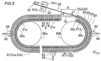
- the one end 31 having a narrow width is inserted into the gap S in a state where the thin plate-like retainer 30 is sandwiched between the feed rollers 81a and 81b.
- one end portion of the endless belt-like retainer 30 starts from the first element 20a adjacent to the section A in a state where the plurality of elements 20 are not arranged in the section A of the ring 10.
- 31 is inserted in the gap S (see FIG. 7) along the direction of the arrow J1 (X1).
- the retainer 30 makes a round in the gap S (see FIG. 7) extending in a track shape with the one end 31 as the head.
- the retainer 30 is quickly passed through the interior (gap S) of the element 20 corresponding to the section B (see FIG. 6).
- the length of the section A (the number of elements 20b (see FIG. 11) not attached in the retainer insertion process) is such that the retainer 30 can be fed into the gap S from the element 20a adjacent to the section A. It is preferable to be as short as possible. This shortens the time for assembling the element 20b (see FIG. 11) prior to the connecting step described later.
- a hook member 90 (see FIG. 8) is attached to the tip of the one end portion 31 and slightly protrudes in the thickness direction.
- the tip of the portion 31 is configured to easily pass between the guide rollers 82 to 84 and the outer peripheral surface 12 of the ring 10.
- the feed rollers 81a and 81b are configured as a single movable unit 81c.
- the movable unit 81c also reaches the vicinity of the section A along the arrow J1 direction. Is configured to move.
- the other end 32 is fed from the feed rollers 81 a and 81 b and placed on the outer peripheral surface 12 of the ring 10. In this way, the retainer 30 is circumferentially arranged along the outer peripheral surface 12 of the ring 10.
- the plate-like member 35 is placed on the upper surfaces (front side of the paper) of the one end portion 31 and the other end portion 32.
- the one end portion 31 and the plate-like member 35 are welded to each other at the portions (three places) of the streaky welding line P with the plate-like member 35 interposed therebetween, and the other end portion 32 and the plate-like member. 35 are welded to each other at three portions of the welding line P.
- the one end part 31 and the other end part 32 are connected to each other.
- the retainer 30 having an annular shape endless annular shape
- the end band shape that prevents the ring 10 from being detached from the recess 25 of the element 20. And inserting the retainer 30 into the gap S between the outer peripheral surface 12 of the ring 10 and the lower surface 23a of the recess 25 facing the base 21 of the flange 23, and arranging the retainer 30 circumferentially along the outer peripheral surface 12 of the ring 10. And a step of connecting the one end 31 and the other end 32 of the end-band retainer 30 to each other.
- the end-band retainer 30 is connected to the outer peripheral surface 12 of the ring 10 and the lower surface 23 a facing the base portion 21 of the flange 23 in the recess 25.
- the metal belt 100 can be completed by connecting the one end 31 and the other end 32 of the retainer 30. Therefore, most of the elements 20 constituting one metal belt 100 can be assembled to the ring 10 side in a short time, so that the assembly work time (lead time) when manufacturing the metal belt 100 can be shortened. it can. In addition, shortening the manufacturing time (lead time) also contributes to reducing the load on the assembly operator.
- the manufacturing method of the metal belt 100 which can improve production efficiency can be provided.
- one metal belt 100 can be manufactured in a shorter time. Can be improved. That is, the production schedule of the metal belt 100 can be flexibly matched to the production demand of the belt type continuously variable transmission (CVT).
- CVT continuously variable transmission
- the width of the step of inserting the end-band retainer 30 into the gap S and arranging it circumferentially along the outer peripheral surface 12 of the ring 10 is reduced.
- the one end 31 of the retainer 30 is inserted into the gap S, and the one end 31 is arranged along the outer peripheral surface 12 of the ring 10 in a circumferential manner.
- one end 31 in a narrowed state width W4
- width W4 is smoothly inserted into the gap S between the outer peripheral surface 12 of the ring 10 and the lower surface 23a of the recess 25 facing the base 21 of the flange 23. Therefore, the inside of the gap S formed in a track shape can be easily made in a short time with the one end 31 of the retainer 30 as the head in the feed direction.
- the step of inserting the one end portion 31 into the gap S and arranging the one end portion 31 along the outer peripheral surface 12 of the ring 10 using the hook member 90 is performed. It is configured to include a step of inserting the pair of hole portions 31d formed in the vicinity of the tip end portion 31a (31b) of the one end portion 31 into the gap S in a state where the width of the one end portion 31 is narrowed. .
- the hook member 90 is used to easily narrow the distal end portion of the one end portion 31, and this state is maintained by the hook member 90, while the entire retainer 30 is placed in the gap S formed in a track shape. It is possible to make a round in an easy and short time along.
- the step of inserting the end-band retainer 30 into the gap S and arranging it in a circumferential manner along the outer peripheral surface 12 of the ring 10 is performed in the section A of the ring 10.
- the step of inserting the one end 31 of the end-band retainer 30 into the gap S starting from the element 20a adjacent to the section A is included.
- the element 20 is arranged after the end-band retainer 30 is inserted into the gap S and arranged circumferentially along the outer peripheral surface 12 of the ring 10.
- the process further includes the step of assembling the remaining element 20b (see FIG. 11) in the section A which is not in the state.
- a complete track-shaped (annular) metal belt 100 can be easily formed simply by assembling a small number of elements 20b (see FIG. 11) corresponding to the section A to the elements 20 arranged in advance in the section B. Can do.
- the step of assembling the remaining elements 20 in the section A is performed at one end 31 of the retainer 30 arranged circumferentially along the outer peripheral surface 12 of the ring 10.
- the other end portion 32 is positioned in the section A and includes a step of assembling the remaining element 20b (see FIG. 11) to the one end portion 31 and the other end portion 32 whose widths are narrowed. Accordingly, the one end 31 (width W4) and the other end 32 (width W2), which are narrower than the width W3 of the main body 33, are positioned in the section A without the element 20, and the ring 10
- the recess 25 of the remaining element 20b can be easily fitted into the inner peripheral surface 11 from the inside of the ring 10 (the inner peripheral surface 11 side).
- the step of connecting the one end 31 and the other end 32 of the retainer 30 is performed in the section A in which the remaining element 20b (see FIG. 11) is assembled. It comprises so that the process of connecting the one end part 31 and the other end part 32 in the corresponding position may be included.
- the retainer 30 can be formed in an endless shape (annular shape with no end) immediately after the element 20b is assembled in the section A to form a complete track-shaped metal belt 100.
- the width W4 of the narrowed one end 31 is not narrowed in the step of connecting the one end 31 and the other end 32 in the section A.
- the state (width W3) is restored to include a step of connecting the one end 31 and the other end 32.
- both end portions (one end portion 31 and the other end portion 32) of the retainer 30 in the width direction (Y-axis direction) are connected to both end portions of the outer peripheral surface 12 of the ring 10 in the width direction (Y-axis direction).
- a state in which the concave portion 25 is securely disposed in the gap S (see FIG.
- the step of connecting the one end portion 31 and the other end portion 32 of the retainer 30 is performed with the one end portion 31 and the other end portion 32 in a state of facing each other.
- the process includes a step of connecting by welding with a plate-like member 35 covering the substrate interposed therebetween.
- the one end 31 and the plate-like member 35 are connected by welding and the other end 32 and the plate-like member 35 are connected by welding, whereby the one end 31 and the other end 32 are plate-like. Since the members 35 can be connected to each other, the connection strength between the one end portion 31 and the other end portion 32 can be ensured.
- the damage to the ring 10 accompanying welding can be suppressed as much as possible by interposing the plate-like member 35.
- first modification of the first embodiment will be described with reference to FIGS. 4 and 12.
- the metal belt 110 is manufactured using a retainer 130 having one end 131 and the other end 132 having a shape different from that of the first embodiment.
- the one end portion 131 and the other end portion 132 are examples of the “start end portion” and the “end end portion” in the claims, respectively.
- the retainer 130 is an example of the “end strip-shaped retaining member” in the claims.
- the same reference numerals are used for the same components as those in the first embodiment.
- the metal belt 110 is manufactured using a retainer 130 having one end 131 and the other end 132, as shown in FIG. That is, the retainer 130 corresponds to the shape of the notch 131c and the one end 131 having the tip portions 131a and 131b left on both sides of the notch 131c notched in a shape similar to a keyhole (valley shape).
- the other end portion 132 formed in a tapered shape (mountain shape) in which the width of the tip end portion 132a is tapered is provided in advance. Note that chamfering is performed so that the tip portions of the tip portions 131a and 131b and the other end portion 132 are not completely sharpened.
- the inside of the gap S extending in a track shape with the one end 131 of the retainer 130 having a narrow width as a head is wound once in a circumferential shape.
- the one end part 131 and the plate-shaped member 35 are the streak-like welding line P in the state in which the opposing part of the valley-shaped one end part 131 and the mountain-shaped other end part 132 was aligned with the section A.
- the other end 132 and the plate-like member 35 are welded to each other at the portion (three locations) of the welding line P. Thereby, the one end 131 and the other end 132 are connected to each other. In this way, the metal belt 110 is manufactured.
- the retainer is configured to have an uneven shape (opposite shape) at an end different from the retainer 30 (see FIG. 4) in the first embodiment. Even if 130 is used, the metal belt 110 can be manufactured under a shorter assembly work time. Other effects are the same as those in the first embodiment.
- the metal belt 120 is manufactured using a retainer 230 having one end 31 and the other end 232 as shown in FIG. That is, the retainer 230 is provided in advance with one end portion 31 having tip portions 31a and 31b on both sides of the notch portion 31c and the other end portion 232 having no tip portion 32a (see FIG. 4). Then, after making a round in the gap S (see FIG.
- the retainer is configured to have an uneven shape (opposite shape) at an end different from the retainer 30 (see FIG. 4) in the first embodiment. Even if 230 is used, the metal belt 120 can be manufactured under a shorter assembly operation time. Other effects are the same as those in the first embodiment.
- the retainer 30 is inserted into the gap S with the other end 32 side as a head and wound once in a circumferential shape, and then the other end 32 and one end
- the one end portion 31 and the other end portion 32 are examples of a “terminal portion” and a “start end portion” in the claims, respectively.
- the same reference numerals are used for the same components as those in the first embodiment.
- the other end 32 of the retainer 30 is inserted into the gap S (see FIG. 7) with the arrow J1 (X1). While inserting along the direction, the inside of the gap S extending in a track shape with the other end 32 as the head is made a round. Also in this case, a hook member 90 (see FIG. 8) is attached to the one end portion 31 so that the width is narrowed in advance. As in the case of FIG. 10, the remaining element 20 b is assembled in the section A in the same manner as in FIG. 11, with the other end 32 and the one end 31 of the retainer 30 positioned in the section A. .
- the other end portion 32 and the plate-like member 35 with the plate-like member 35 interposed therebetween are welded to each other at the portions (three places) of the welding line P, and the one end portion 31 and the plate-like member 35 are welded to each other at the portions (three places) of the line-like welding line P. Thereby, the one end part 31 and the other end part 32 are mutually connected.
- Other manufacturing processes for the metal belt 200 are the same as those in the first embodiment.
- the metal belt 200 can be manufactured with a shorter assembly time even if the insertion direction of the retainer 30 is reversed to that of the first embodiment. Other effects are the same as those in the first embodiment.
- FIGS. 5, 11, and 15 a third embodiment will be described with reference to FIGS. 5, 11, and 15.
- the metal belt 300 is manufactured by directly connecting the one end 31 and the other end 32 of the retainer 30 without using the plate-like member 35 (see FIG. 5) will be described.
- the same reference numerals are used for the same components as those in the first embodiment.
- the remaining elements 20b are disposed in the portions of the one end 31 and the other end 32 where the width located in the section A is narrowed. Is assembled. Then, after the hook member 90 is removed, as shown in FIG. 15, each of the peripheral edges 31e and 32e is directly along the welding line R with the one end 31 and the other end 32 facing each other. Welded. In this way, the metal belt 300 is manufactured. Other manufacturing processes of the metal belt 300 are the same as those in the first embodiment.
- the connection strength between the one end portion 31 and the other end portion 32 can be ensured without using the plate-like member 35 (see FIG. 5). .
- the metal belt 300 can be manufactured under shorter assembly work time. Other effects are the same as those in the first embodiment.
- the hook member 90 is temporarily fastened to the pair of holes 31d to narrow the width of the one end 31, but the present invention is not limited to this.
- the metal belt 400 may be manufactured by applying the manufacturing process in the modification of the present invention shown in FIGS. 16 and 17. Specifically, as shown in FIG. 16, a pair of bent tip portions 91 a and 91 b on the gripping portion side for gripping a part using a plier 91 by an assembly operator (not shown) are provided at one end portion. 31 are respectively inserted into the pair of holes 31d of the tip portions 31a and 31b.
- the assembly operator uses the pliers 91 to narrow the width of the one end 31.
- the retainer 30 is wound around the outer peripheral surface 12 of the ring 10 once in a circumferential shape.
- the movable unit 81c, the guide rollers 82 to 84, the shape maintaining rollers 80a and 80b (see FIG. 9) and the like as shown in the first embodiment are not necessary.
- the pliers 91 are an example of the “jigs” in the claims.
- the entire retainer 30 is formed in a track shape while maintaining the state by the pliers 91 in a state where the tip end portion of the one end portion 31 is easily narrowed using the pliers 91. It is possible to make a round in the gap S easily and in a short time. Therefore, the metal belt 400 can be manufactured under a shorter required time (lead time).
- the pliers 91 used by the assembly operator are used as an example of the “jig”, but this is not restrictive. That is, a mechanical device that automatically pinches the tip portion of the one end portion 31 to narrow the width may be used.
- the other end 132 having a simple taper shape is connected to the keyhole-shaped notch 131c so as to face each other, but the present invention is not limited to this. Absent.
- the distal end 132a of the other end 132 may be formed in an arc shape that can be fitted into the keyhole shape of the notch 131c.
- the one end 31 (131) and the other end 32 (232) have an uneven shape.
- the present invention is not limited to this.
- a shape similar to that of the one end portion 31 is provided at both ends of the retainer (end-end strip-shaped retaining member), and the end portions formed in the same shape are opposed to each other by winding the retainer once in a circumferential shape. Then, they may be connected to each other via the plate-like member 35.
- the present invention is applied to a method of manufacturing metal belts 100 to 400 for a belt type continuously variable transmission (CVT) mounted on a vehicle (not shown).
- CVT continuously variable transmission
- the present invention is not limited to this.
- manufacture of a metal belt for a power transmission device other than a belt-type continuously variable transmission mounted on a vehicle The present invention may be applied to a method.
Landscapes
- Engineering & Computer Science (AREA)
- General Engineering & Computer Science (AREA)
- Mechanical Engineering (AREA)
- Rolling Contact Bearings (AREA)
- Package Frames And Binding Bands (AREA)
- Automatic Assembly (AREA)
Abstract
この金属ベルトの製造方法は、有端帯状の抜止部材(30,130)を、リング(10)の外周面(12)と凹部(25)における庇部(23)の基部(21)に対向する内面との隙間に挿入するとともにリング(10)の外周面(12)に沿って周状に配置する工程と、有端帯状の抜止部材(30,130)の始端部と終端部とを連結する工程と、を備える。
Description
本発明は、金属ベルトの製造方法および金属ベルトに関する。
従来、無端環状のリングとこのリングに沿って周状に配列された複数のエレメントとを備えた金属ベルトが知られている。このような金属ベルトは、たとえば、特開2001-193796号公報に開示されている。
特開2001-193796号公報には、駆動プーリと被動(従動)プーリとに掛けられることにより駆動プーリの動力を被動プーリに伝達する金属ベルトが開示されている。この金属ベルトは、無端環状の金属製のバンド(リング)と、このバンドを保持する凹部を含む複数の金属製のエレメントと、バンドがエレメントの凹部から離脱するのを防止する無端帯状の金属製の脱落防止体(抜止部材)とを備えている。なお、金属ベルトの断面構造として、脱落防止体の幅がバンドの幅よりも大きく形成されている。そして、バンドがエレメントの凹部に装着された状態で脱落防止体がバンドの外周面を覆うとともに両縁部が凹部の庇部に係止されることによって、バンドが凹部から離脱しないように構成されている。また、脱落防止体には厚み方向に貫通し長手方向に所定距離だけ延びた長孔が形成されている。したがって、この金属ベルトの製造プロセスでは、バンド(リング)の外周面に脱落防止体を沿わせるとともに長孔が設けられた区間の脱落防止体の幅を局所的に狭めた状態で、エレメントの凹部をバンドおよび脱落防止体の幅狭部分に嵌め込む。そして、脱落防止体は、幅が狭められた状態で凹部に挿入された後、凹部内で幅が元の大きさに復元されることにより脱落防止体の両縁部が凹部の庇部に係止されるように構成されている。
しかしながら、特開2001-193796号公報に記載された金属ベルトでは、製造プロセスにおいて、長孔が設けられた区間の脱落防止体(抜止部材)の幅を局所的に狭めながらエレメントを1枚ないし2枚ずつバンド側に嵌め込んで順送りする必要があるため、まとまった数のエレメントをバンド側に組み付けることができない。このため、全てのエレメントを組み付けて環状の金属ベルトを完成させるまでに多くの組付け作業時間を要するという問題点がある。
この発明は、上記のような課題を解決するためになされたものであり、この発明の1つの目的は、組付け作業時間を短縮することが可能な金属ベルトの製造方法およびこの金属ベルトを提供することである。
上記目的を達成するために、この発明の第1の局面における金属ベルトの製造方法は、基部と、庇部と、基部と庇部とを接続する接続部とによって無端環状のリングを保持する凹部が構成されている金属ベルト用のエレメントを、リングに順次嵌め込むとともにリングに沿って配列させる工程と、複数のエレメントがリングに配列された状態で、リングがエレメントの凹部から離脱するのを防止する有端帯状の抜止部材を、リングの外周面と凹部における庇部の基部に対向する内面との隙間に挿入するとともにリングの外周面に沿って周状に配置する工程と、有端帯状の抜止部材の始端部と終端部とを連結する工程と、を備える。
この発明の第1の局面による金属ベルトの製造方法は、上記のように、複数のエレメントがリングに配列された状態で、リングがエレメントの凹部から離脱するのを防止する有端帯状の抜止部材を、リングの外周面と凹部における庇部の基部に対向する内面との隙間に挿入するとともにリングの外周面に沿って周状に配置する工程と、有端帯状の抜止部材の始端部と終端部とを連結する工程とを備える。これにより、多数のエレメントがリングに予め配列(整列)された状態で有端帯状の抜止部材をリングの外周面と凹部における庇部の基部に対向する内面との隙間に挿入して周状に1回巻きした後、この抜止部材の始端部と終端部とを連結して金属ベルトを完成させることができる。したがって、1本の金属ベルトを構成するほとんどのエレメントを短時間でリング側に組み付けることができるので、金属ベルトを製造する際の組付け作業時間を短縮することができる。また、より短時間で1本の金属ベルトを製造することができるので、生産効率を向上させることが可能な金属ベルトの製造方法を提供することができる。
この発明の第2の局面における金属ベルトは、無端環状のリングと、各々がリングを保持する凹部を含む複数のエレメントと、複数のエレメントがリングに配列された状態でリングの外周面に沿って周状に配置され、かつ、始端部と終端部とが互いに連結されているとともに、リングがエレメントの凹部から離脱するのを防止する有端帯状の抜止部材と、を備える。
この発明の第2の局面による金属ベルトは、上記のように、複数のエレメントがリングに配列された状態でリングの外周面に沿って周状に配置され、かつ、始端部と終端部とが互いに連結されているとともに、リングがエレメントの凹部から離脱するのを防止する有端帯状の抜止部材を備える。これにより、製造プロセス上、多数のエレメントがリングに予め配列された状態で有端帯状の抜止部材をリングの外周面と凹部の内面(凹部における庇部の基部に対向する内面)との隙間に挿入して周状に1回巻きした後、この抜止部材の始端部と終端部とを連結して金属ベルトを完成させることができる。したがって、1本の金属ベルトを構成するほとんどのエレメントを短時間でリング側に組み付けることができるので、金属ベルトを製造する際の組付け作業時間を短縮することができる。また、より短時間で1本の金属ベルトを製造することができるので、生産効率を向上させることが可能な金属ベルトを提供することができる。
本発明によれば、上記のように、金属ベルトを製造する際の組付け作業時間を短縮することができる。
以下、本発明の実施形態を図面に基づいて説明する。
[第1実施形態]
まず、図1~図5を参照して、第1実施形態による金属ベルト100の構成について説明する。
まず、図1~図5を参照して、第1実施形態による金属ベルト100の構成について説明する。
(金属ベルトの構成)
本発明の第1実施形態による製造方法を用いて製造された金属ベルト100は、図1に示すように、リング10と、複数のエレメント20と、リテーナ30とを備える。金属ベルト100は、車両(図示せず)に搭載されたベルト式無段変速機(CVT)における駆動側(入力軸)プーリ(図示せず)と、従動側(出力軸)プーリ(図示せず)とに巻き掛けられるとともに、それらのプーリ間で動力を伝達する役割を担う機械要素部品である。なお、図1では、説明の都合上、一部の区間のエレメント20を破線で示して、内部に組み込まれたリング10の構造および後述するリテーナ30の連結構造を実線で示している。
本発明の第1実施形態による製造方法を用いて製造された金属ベルト100は、図1に示すように、リング10と、複数のエレメント20と、リテーナ30とを備える。金属ベルト100は、車両(図示せず)に搭載されたベルト式無段変速機(CVT)における駆動側(入力軸)プーリ(図示せず)と、従動側(出力軸)プーリ(図示せず)とに巻き掛けられるとともに、それらのプーリ間で動力を伝達する役割を担う機械要素部品である。なお、図1では、説明の都合上、一部の区間のエレメント20を破線で示して、内部に組み込まれたリング10の構造および後述するリテーナ30の連結構造を実線で示している。
また、図2および図3に示すように、リング10は、無端環状の金属薄板10aが板厚方向(Z軸方向)に複数枚積層されている。エレメント20は、金属製であり、個々のエレメント20は、外周側(金属ベルト100の回転半径方向外側)に、多層状となったリング10を保持(収容)するための凹部25が形成されている。また、エレメント20は、凹部25においてリング10を保持する底部22を有する基部21と、リング10およびリテーナ30が組み付けられた状態でリテーナ30が凹部25から外れるのを防止する一対の庇部23と、基部21と庇部23とを接続する接続部24とを有して構成されている。また、底部22、接続部24および庇部23によって、凹部25における凹状の内面25aが構成されている。また、リテーナ30は、リング10(最外層の金属薄板10a)の外周面12と凹状の内面25aのうちの一対の庇部23の下面23a(矢印Z2側)との間の隙間Sに挟み込まれている。そして、この状態で、リテーナ30は、図1に示すように、リング10の回転半径方向外側の外周面12に沿って周状(トラック状)に配置されている。なお、下面23aは、特許請求の範囲の「凹部における庇部の基部に対向する内面」の一例である。
なお、接続部24から庇部23にかけての一対の外側面26は、駆動側プーリおよび従動側プーリ(図示せず)の各々のV字状の溝(摺動面)に嵌まり込んで面接触する部分である。また、リテーナ30は、金属製(マルエージング鋼製)であり、リング10がエレメント20の凹部25から金属ベルト100の回転半径方向外側に離脱するのを防止する役割を有する。なお、リテーナ30は、特許請求の範囲の「有端帯状の抜止部材」の一例である。
ここで、第1実施形態では、図4に示すように、リテーナ30は、金属ベルト100の製造プロセス上、有端帯状に形成されている。すなわち、リテーナ30は、単体状態では、一方端部31と、他方端部32と、一方端部31および他方端部32を繋ぐ本体部33とを有する。一方端部31は、本体部33のX軸方向に沿った中心線(図示せず)を対称軸として幅方向(Y軸方向)に2股(左右対称)に分岐されるとともにX軸方向に互いに平行に延びる一対の先端部31aおよび31bを有する。すなわち、Y2側の先端部31aとY1側の先端部31bとが幅方向に対向する部分に、U字状に切り欠かれた切欠部31cが設けられている。また、先端部31aおよび31bの各々には、厚み方向(Z軸方向)に貫通する孔部31dが形成されている。また、他方端部32は、本体部33の中心線(図示せず)に沿って延びるとともに本体部33に対して幅W2が小さく形成された1本の先端部32aを有する。なお、先端部32aの幅W2は、一方端部31における切欠部31cの幅W1よりも僅かに小さい。また、本体部33は、一方端部31との境界部分から他方端部32との境界部分に亘って一定の幅W3を有する。なお、一方端部31および他方端部32は、それぞれ、特許請求の範囲の「始端部」および「終端部」の一例である。
そして、図5に示すように、製造後の金属ベルト100においては、複数のエレメント20がリング10(最内層の金属薄板10a)の内周面11に沿って周状に配置された状態(図1参照)で、リテーナ30の一方端部31と他方端部32とが板状部材35を介在させて互いに連結(溶接)されている。
(金属ベルトの製造方法)
次に、図1、図2および図5~図11を参照して、本発明の第1実施形態による金属ベルト100の製造プロセスについて説明する。
次に、図1、図2および図5~図11を参照して、本発明の第1実施形態による金属ベルト100の製造プロセスについて説明する。
〈エレメントの配列工程〉
まず、図6に示すように、無端環状のリング10を一対の形状保持ローラ80aおよび80b間に掛けまわすとともに、形状保持ローラ80aおよび80bを互いにX軸方向に所定距離だけ離間させることによって、リング10がトラック状(長円形状)に形成される。そして、トラック状となったリング10に対して複数枚のエレメント20を配列する。具体的には、リング10の内周面11に対して、エレメント20の凹部25がリング10の内側(内周面11の側)から嵌め込まれる。
まず、図6に示すように、無端環状のリング10を一対の形状保持ローラ80aおよび80b間に掛けまわすとともに、形状保持ローラ80aおよび80bを互いにX軸方向に所定距離だけ離間させることによって、リング10がトラック状(長円形状)に形成される。そして、トラック状となったリング10に対して複数枚のエレメント20を配列する。具体的には、リング10の内周面11に対して、エレメント20の凹部25がリング10の内側(内周面11の側)から嵌め込まれる。
この際、第1実施形態では、複数のエレメント20を配列しない区間Aを残した状態で、他のほとんどの区間Bにエレメント20が配列される。なお、形状保持ローラ80aおよび80bとのX軸方向の間隔が適切に調整されることによって、複数のエレメント20が配列(整列)された状態で、エレメント20の基部21の回転半径方向内側となる下面21aが形状保持ローラ80aおよび80bの外表面80cに接触する。これにより、個々のエレメント20が適切に配列されるとともに、図6のように1枚1枚順次列をなした状態で保持される。また、これにより、図7に示すように、エレメント20の凹部25にリング10が配置(収容)される。なお、リング10の外周面12の幅方向(Y軸方向)の両端部と、凹部25における庇部23の基部21に対向する下面23aとの間には、隙間Sが形成される。また、この隙間Sは、エレメント20が配列された方向(X軸方向)に沿って区間Bに亘って連続的に延びている。なお、区間Aは、特許請求の範囲の「一部区間」の一例である。
その後、図8に示すように、短冊状(細長状)に形成されたリテーナ30の一方端部31に形成された先端部31aおよび31bが互いに近づけられることにより一方端部31の幅Wが狭められる。この際、組立作業者(図示せず)が、予めU字状に形成されたフック部材90の一対の端部90aおよび90bを、先端部31aおよび31bに予め形成された一対の孔部31dにそれぞれ挿入する。これにより、一方端部31は、先端部31aと先端部31bとが互いに近づけられるようにその形状が矯正されて一方端部31の幅4が狭められる。すなわち、一方端部31の根元部(X2側)で幅W3であったものが、一方端部31の先端(X1側)では幅W4(W4<W3)へと減少される。
なお、先端部31aと先端部31bとの接近距離は、切欠部31c周辺(先端部31aおよび31bの根元部分)での金属部材の曲げ変形に起因して一方端部31のZ方向の厚み(外形形状)が極度に膨らまない程度の距離に調整されている。また、幅W4は、エレメント20における左右の庇部23(図7参照)のY軸方向の離間間隔W5よりも小さい。なお、図8では、幅が狭められる前の一方端部31の外形形状を二点鎖線で示すとともに、フック部材90を取り付けた後の先端部31aおよび31bの外形形状を太い実線で示している。なお、フック部材90は、特許請求の範囲の「形状保持部材」の一例である。
〈リテーナの挿入工程〉
その後、図9に示すように、エレメント20がリング10に配列(整列)された状態で、有端帯状のリテーナ30が、リング10の外周面12と凹部25における庇部23の基部21に対向する下面23aとの間の隙間Sに挿入される。具体的には、リテーナ30を保持するとともにリテーナ30をエレメント20内に自動的に送るための送りローラ81aおよび81bと、リテーナ30をリング10に沿って矢印X1方向に周状に1回巻きする際の送り動作をガイドするガイドローラ82~84とがセットされる。なお、ガイドローラ82~84にはバネ部材85が設けられており、自身が回転するガイドローラ82~84は、所定の押圧力でリング10の外周面12を押圧している。
その後、図9に示すように、エレメント20がリング10に配列(整列)された状態で、有端帯状のリテーナ30が、リング10の外周面12と凹部25における庇部23の基部21に対向する下面23aとの間の隙間Sに挿入される。具体的には、リテーナ30を保持するとともにリテーナ30をエレメント20内に自動的に送るための送りローラ81aおよび81bと、リテーナ30をリング10に沿って矢印X1方向に周状に1回巻きする際の送り動作をガイドするガイドローラ82~84とがセットされる。なお、ガイドローラ82~84にはバネ部材85が設けられており、自身が回転するガイドローラ82~84は、所定の押圧力でリング10の外周面12を押圧している。
そして、薄板状のリテーナ30を送りローラ81aおよび81b間に挟み込んだ状態で、幅が狭められた一方端部31が隙間Sに挿入される。この際、第1実施形態では、リング10の区間Aに複数のエレメント20を配列していない状態で、区間Aに隣接する最初のエレメント20aを起点として、有端帯状のリテーナ30の一方端部31が隙間S(図7参照)に矢印J1(X1)方向に沿って挿入される。そして、送りローラ81aおよび81bの回転駆動とともに、リテーナ30が一方端部31を先頭としてトラック状に延びる隙間S(図7参照)内を一巡される。すなわち、リテーナ30は、区間B(図6参照)に相当するエレメント20の内部(隙間S)に迅速に通される。なお、区間Aの長さ(リテーナの挿入工程で取り付けられないエレメント20b(図11参照)の枚数)は、区間Aに隣接するエレメント20aからリテーナ30を隙間Sに送り入れることが可能な程度に極力短いのが好ましい。これにより、後述する連結工程に先立ってエレメント20b(図11参照)を組み付ける時間が短縮される。
なお、一方端部31の先端には、フック部材90(図8参照)が取り付けられて厚み方向にやや突出しているが、ガイドローラ82~84に設けられたバネ部材85の伸縮作用によって一方端部31の先端がガイドローラ82~84とリング10の外周面12にとの間を容易に通り抜けるように構成されている。また、送りローラ81aおよび81bは1つの可動ユニット81cとして構成されている。これにより、リテーナ30を、おおよそ1回巻きして送りローラ81aおよび81bのリテーナ30を保持する部分が他方端部32に近づき始めると、可動ユニット81cも矢印J1方向に沿って区間Aの近傍まで移動するように構成されている。そして、他方端部32が送りローラ81aおよび81bから送り出されてリング10の外周面12上に載置される。このようにして、リテーナ30は、リング10の外周面12に沿わせて周状に配置される。
〈リテーナの連結工程〉
その後、図10に示すように、リング10の外周面12に沿わせて周状に配置されたリテーナ30の一方端部31および他方端部32を区間Aに位置させる。そして、図11に示すように、区間Aに位置された幅が狭められている一方端部31および他方端部32の部分に、残りのエレメント20bが組み付けられる。その後、図10においてフック部材90が一対の孔部31dに仮留めされていた状態から、図5に示すように、フック部材90が一対の孔部31dから取り外されることにより、幅が狭められている一方端部31の幅W4を、幅が狭められていない元の状態(幅W3の状態)に戻す。
その後、図10に示すように、リング10の外周面12に沿わせて周状に配置されたリテーナ30の一方端部31および他方端部32を区間Aに位置させる。そして、図11に示すように、区間Aに位置された幅が狭められている一方端部31および他方端部32の部分に、残りのエレメント20bが組み付けられる。その後、図10においてフック部材90が一対の孔部31dに仮留めされていた状態から、図5に示すように、フック部材90が一対の孔部31dから取り外されることにより、幅が狭められている一方端部31の幅W4を、幅が狭められていない元の状態(幅W3の状態)に戻す。
そして、この状態で一方端部31および他方端部32の上面(紙面手前側)に板状部材35が被せられる。そして、板状部材35を介在させた状態で一方端部31と板状部材35とが筋状の溶接ラインPの部分(3箇所)で互いに溶接されるとともに、他方端部32と板状部材35とが溶接ラインPの部分(3箇所)で互いに溶接される。これにより、一方端部31と他方端部32とが互いに連結される。このようにして、環状(無端環状)となったリテーナ30がリング10の外周面12に沿って凹部25内に固定される。最後に、可動ユニット81c、ガイドローラ82~84および形状保持ローラ80aおよび80b(図9参照)が取り外されることによって金属ベルト100(図1参照)が製造される。
(第1実施形態の金属ベルトの製造方法の効果)
第1実施形態では、以下のような効果を得ることができる。
第1実施形態では、以下のような効果を得ることができる。
第1実施形態による金属ベルト100の製造プロセスでは、上記のように、複数のエレメント20がリング10に配列された状態で、リング10がエレメント20の凹部25から離脱するのを防止する有端帯状のリテーナ30を、リング10の外周面12と凹部25における庇部23の基部21に対向する下面23aとの隙間Sに挿入するとともにリング10の外周面12に沿って周状に配置する工程と、有端帯状のリテーナ30の一方端部31と他方端部32とを連結する工程とを備える。これにより、多数のエレメント20がリング10に予め配列(整列)された状態で有端帯状のリテーナ30をリング10の外周面12と凹部25における庇部23の基部21に対向する下面23aとの隙間Sに挿入して周状に1回巻きした後、このリテーナ30の一方端部31と他方端部32とを連結して金属ベルト100を完成させることができる。したがって、1本の金属ベルト100を構成するほとんどのエレメント20を短時間でリング10側に組み付けることができるので、金属ベルト100を製造する際の組付け作業時間(リードタイム)を短縮することができる。加えて、製造所要時間(リードタイム)の短縮は、組立作業者の負荷の軽減にも寄与する。また、より短時間で1本の金属ベルト100を製造することができるので、生産効率を向上させることが可能な金属ベルト100の製造方法を提供することができる。
また、第1実施形態では、金属ベルト100を上記した製造プロセスを適用して製造することによって、より短時間で1本の金属ベルト100を製造することができるので、金属ベルト100の生産効率を向上させることができる。すなわち、ベルト式無段変速機(CVT)の生産需要に合わせて金属ベルト100の生産スケジュールを柔軟に対応させることができる。
また、第1実施形態による金属ベルト100の製造プロセスでは、有端帯状のリテーナ30を隙間Sに挿入するとともにリング10の外周面12に沿って周状に配置する工程を、幅が狭められているリテーナ30の一方端部31を隙間Sに挿入するとともに、一方端部31をリング10の外周面12に沿わせて周状に配置する工程を含むように構成する。これにより、幅が狭められた状態(幅W4の状態)の一方端部31をリング10の外周面12と凹部25における庇部23の基部21に対向する下面23aとの隙間Sに円滑に挿入することができるので、リテーナ30の一方端部31を送り方向の先頭として、トラック状に形成された隙間S内を容易にかつ短時間で一巡させることができる。
また、第1実施形態による金属ベルト100の製造プロセスでは、一方端部31を隙間Sに挿入するとともにリング10の外周面12に沿わせて周状に配置する工程を、フック部材90を用いて一方端部31の先端部31a(31b)近傍に予め形成された一対の孔部31dを互いに近づけることにより一方端部31の幅を狭めた状態で隙間Sに挿入する工程を有するように構成する。これにより、フック部材90を用いて一方端部31の先端部分を容易に狭めた状態で、この状態をフック部材90により維持しつつ、リテーナ30全体を、トラック状に形成された隙間S内に沿って容易にかつ短時間で一巡させることができる。
また、第1実施形態による金属ベルト100の製造プロセスでは、有端帯状のリテーナ30を隙間Sに挿入するとともにリング10の外周面12に沿って周状に配置する工程を、リング10の区間Aに複数のエレメント20を配列していない状態で、区間Aに隣接するエレメント20aを起点として有端帯状のリテーナ30の一方端部31を隙間Sに挿入する工程を含むように構成する。これにより、区間A以外の区間Bに相当する大多数のエレメント20を予めリング10に対して配列(整列)しておいた状態で、区間B内にトラック状に連続性を有して延びる隙間Sにリテーナ30全体を短時間で一巡させることができる。
また、第1実施形態による金属ベルト100の製造プロセスでは、有端帯状のリテーナ30を隙間Sに挿入するとともにリング10の外周面12に沿わせて周状に配置した後、エレメント20が配列されていない状態の区間Aに残りのエレメント20b(図11参照)を組み付ける工程をさらに備える。これにより、区間Bに予め配列されたエレメント20に対して区間Aに相当する少数のエレメント20b(図11参照)を組み付けるだけで完全なトラック状(環状)の金属ベルト100を容易に形成することができる。
また、第1実施形態による金属ベルト100の製造プロセスでは、残りのエレメント20を区間Aに組み付ける工程を、リング10の外周面12に沿わせて周状に配置されたリテーナ30の一方端部31および他方端部32を区間Aに位置させるとともに幅が狭められている一方端部31および他方端部32に、残りのエレメント20b(図11参照)を組み付ける工程を含むように構成する。これにより、本体部33の幅W3よりも幅が狭められた一方端部31(幅W4)および他方端部32(幅W2)をエレメント20のない区間Aに位置させた状態で、リング10の内周面11に対して、残りのエレメント20b(図11参照)の凹部25をリング10の内側(内周面11の側)から容易に嵌め込むことができる。
また、第1実施形態による金属ベルト100の製造プロセスでは、リテーナ30の一方端部31と他方端部32とを連結する工程を、残りのエレメント20b(図11参照)が組み付けられた区間Aに対応した位置で一方端部31と他方端部32とを連結する工程を含むように構成する。これにより、区間Aにエレメント20bを組み付けて完全なトラック状の金属ベルト100にした状態で、直ちに、リテーナ30を無端状(端部のない環状)に形成することができる。
また、第1実施形態による金属ベルト100の製造プロセスでは、区間Aにおいて一方端部31と他方端部32とを連結する工程を、狭められている一方端部31の幅W4を狭められていない状態(幅W3)に復元して一方端部31と他方端部32とを連結する工程を有するように構成する。これにより、区間Aにおいてもリテーナ30の幅方向(Y軸方向)の両端部(一方端部31および他方端部32)を、リング10の外周面12の幅方向(Y軸方向)の両端部と凹部25における庇部23の基部21に対向する下面23aとの間の隙間S(図3参照)に確実に配置した状態(一方端部31と他方端部32とが厚み方向に重ならない状態)で、一方端部31と他方端部32とを確実に連結することができる。
また、第1実施形態による金属ベルト100の製造プロセスでは、リテーナ30の一方端部31と他方端部32とを連結する工程を、互いに対向させた状態の一方端部31と他方端部32とを覆う板状部材35を介在させて溶接により連結する工程を含むように構成する。これにより、一方端部31と板状部材35とを溶接により連結するとともに他方端部32と板状部材35とを溶接により連結することによって、一方端部31と他方端部32とを板状部材35を介在させて連結することができるので、一方端部31と他方端部32との連結強度を確実なものにすることができる。また、板状部材35を介在させる分、溶接に伴うリング10へのダメージを極力抑制することができる。
[第1実施形態の第1変形例]
次に、図4および図12を参照して、第1実施形態の第1変形例について説明する。この第1実施形態の第1変形例では、上記第1実施形態とは異なる形状の一方端部131および他方端部132を有するリテーナ130を用いて金属ベルト110を製造する例について説明する。なお、一方端部131および他方端部132は、それぞれ、特許請求の範囲の「始端部」および「終端部」の一例である。また、リテーナ130は、特許請求の範囲の「有端帯状の抜止部材」の一例である。なお、図中において、上記第1実施形態と同様の構成には、同一の符号を用いて図示する。
次に、図4および図12を参照して、第1実施形態の第1変形例について説明する。この第1実施形態の第1変形例では、上記第1実施形態とは異なる形状の一方端部131および他方端部132を有するリテーナ130を用いて金属ベルト110を製造する例について説明する。なお、一方端部131および他方端部132は、それぞれ、特許請求の範囲の「始端部」および「終端部」の一例である。また、リテーナ130は、特許請求の範囲の「有端帯状の抜止部材」の一例である。なお、図中において、上記第1実施形態と同様の構成には、同一の符号を用いて図示する。
第1実施形態の第1変形例による製造プロセスでは、図12に示すように、一方端部131および他方端部132を有するリテーナ130を用いて金属ベルト110が製造される。すなわち、リテーナ130には、鍵穴に似た形状(谷形状)に切り欠かれた切欠部131cの両側に残された先端部131aおよび131bを有する一方端部131と、切欠部131cの形状に対応するように先端部132aの幅が先細るテーパ状(山形状)に形成された他方端部132とが予め設けられている。なお、先端部131a、131bおよび他方端部132の最も先端の部分は完全に尖ることのないように面取り加工が施されている。
そして、上記第1実施形態における金属ベルト100の製造プロセスと同様の製造プロセスによって、幅が狭められたリテーナ130の一方端部131を先頭としてトラック状に延びる隙間S内を周状に1回巻きさせる(リング10上に周状に配置する)。そして、谷形状の一方端部131と、山形状の他方端部132との対向部分が区間Aに位置合わせされた状態で、一方端部131と板状部材35とが筋状の溶接ラインPの部分(3箇所)で互いに溶接されるとともに、他方端部132と板状部材35とが溶接ラインPの部分(3箇所)で互いに溶接される。これにより、一方端部131と他方端部132とが互いに連結される。このようにして、金属ベルト110が製造される。
(第1実施形態の第1変形例の金属ベルトの製造方法の効果)
第1実施形態の第1変形例による金属ベルト110の製造プロセスでは、上記第1実施形態におけるリテーナ30(図4参照)と異なる端部の凹凸形状(対向形状)を有して構成されたリテーナ130を用いても、より短い組付け作業時間のもとで金属ベルト110を製造することができる。なお、その他の効果については上記第1実施形態と同様である。
第1実施形態の第1変形例による金属ベルト110の製造プロセスでは、上記第1実施形態におけるリテーナ30(図4参照)と異なる端部の凹凸形状(対向形状)を有して構成されたリテーナ130を用いても、より短い組付け作業時間のもとで金属ベルト110を製造することができる。なお、その他の効果については上記第1実施形態と同様である。
[第1実施形態の第2変形例]
次に、図4、図7および図13を参照して、第1実施形態の第2変形例について説明する。この第1実施形態の第2変形例では、上記第1実施形態とは異なる形状の他方端部232を有するリテーナ230を用いて金属ベルト120を製造する例について説明する。なお、リテーナ230および他方端部232は、それぞれ、特許請求の範囲の「有端帯状の抜止部材」および「終端部」の一例である。なお、図中において、上記第1実施形態と同様の構成には、同一の符号を用いて図示する。
次に、図4、図7および図13を参照して、第1実施形態の第2変形例について説明する。この第1実施形態の第2変形例では、上記第1実施形態とは異なる形状の他方端部232を有するリテーナ230を用いて金属ベルト120を製造する例について説明する。なお、リテーナ230および他方端部232は、それぞれ、特許請求の範囲の「有端帯状の抜止部材」および「終端部」の一例である。なお、図中において、上記第1実施形態と同様の構成には、同一の符号を用いて図示する。
第1実施形態の第2変形例による製造プロセスでは、図13に示すように、一方端部31および他方端部232を有するリテーナ230を用いて金属ベルト120が製造される。すなわち、リテーナ230には、切欠部31cの両側に先端部31aおよび31bを有する一方端部31と、先端部32a(図4参照)を有しない他方端部232とが予め設けられている。そして、一方端部31の幅を狭めた状態で一方端部31を先頭としてトラック状に延びる隙間S(図7参照)内を一巡させた後、一方端部31に対して他方端部232を対向させた状態で、一方端部31と板状部材35とが枠状の溶接ラインQの一部区間で互いに溶接されるとともに、他方端部232と板状部材35とが溶接ラインQの他の区間で互いに溶接される。これにより、一方端部31と他方端部232とが互いに連結される。このようにして、金属ベルト120が製造される。なお、リテーナ230をリング10と凹部25との隙間Sに挿入して周状に1回巻きさせるリテーナ230の挿入工程は、上記第1実施形態と同様である。
(第1実施形態の第2変形例の金属ベルトの製造方法の効果)
第1実施形態の第2変形例による金属ベルト120の製造プロセスでは、上記第1実施形態におけるリテーナ30(図4参照)と異なる端部の凹凸形状(対向形状)を有して構成されたリテーナ230を用いても、より短い組付け作業時間のもとで金属ベルト120を製造することができる。なお、その他の効果については上記第1実施形態と同様である。
第1実施形態の第2変形例による金属ベルト120の製造プロセスでは、上記第1実施形態におけるリテーナ30(図4参照)と異なる端部の凹凸形状(対向形状)を有して構成されたリテーナ230を用いても、より短い組付け作業時間のもとで金属ベルト120を製造することができる。なお、その他の効果については上記第1実施形態と同様である。
[第2実施形態]
次に、図7、図8、図10、図11および図14を参照して、第2実施形態について説明する。この第2実施形態では、上記第1実施形態とは異なり、リテーナ30を他方端部32の側を先頭として隙間Sに挿入して周状に1回巻きさせた後、他方端部32と一方端部31とを連結する製造プロセスを適用する例について説明する。なお、第2実施形態においては、一方端部31および他方端部32は、それぞれ、特許請求の範囲の「終端部」および「始端部」の一例である。また、図中において、上記第1実施形態と同様の構成には、同一の符号を用いて図示する。
次に、図7、図8、図10、図11および図14を参照して、第2実施形態について説明する。この第2実施形態では、上記第1実施形態とは異なり、リテーナ30を他方端部32の側を先頭として隙間Sに挿入して周状に1回巻きさせた後、他方端部32と一方端部31とを連結する製造プロセスを適用する例について説明する。なお、第2実施形態においては、一方端部31および他方端部32は、それぞれ、特許請求の範囲の「終端部」および「始端部」の一例である。また、図中において、上記第1実施形態と同様の構成には、同一の符号を用いて図示する。
すなわち、第2実施形態による金属ベルト200の製造プロセスでは、図14に示すように、リテーナ30の挿入工程において、リテーナ30の他方端部32を隙間S(図7参照)に矢印J1(X1)方向に沿って挿入するとともに、他方端部32を先頭としてトラック状に延びる隙間S内を一巡させる。なお、この場合も、一方端部31にはフック部材90(図8参照)を取り付けて幅が予め狭められた状態にしている。そして、図10の場合と同様に、リテーナ30の他方端部32および一方端部31を区間Aに位置させた状態で、図11の場合と同様に、区間Aに残りのエレメント20bが組み付けられる。そして、狭められている一方端部31の幅を狭められていない状態に復元した後、図14に示すように、板状部材35を介在させた状態で、他方端部32と板状部材35とが溶接ラインPの部分(3箇所)で互いに溶接されるとともに、一方端部31と板状部材35とが筋状の溶接ラインPの部分(3箇所)で互いに溶接される。これにより一方端部31と他方端部32とが互いに連結される。なお、金属ベルト200のその他の製造プロセスについては上記第1実施形態と同様である。
(第2実施形態の金属ベルトの製造方法の効果)
第2実施形態による金属ベルト200の製造プロセスでは、リテーナ30の挿入方向を上記第1実施形態と逆さにしても、より短い組付け作業時間のもとで金属ベルト200を製造することができる。なお、その他の効果については上記第1実施形態と同様である。
第2実施形態による金属ベルト200の製造プロセスでは、リテーナ30の挿入方向を上記第1実施形態と逆さにしても、より短い組付け作業時間のもとで金属ベルト200を製造することができる。なお、その他の効果については上記第1実施形態と同様である。
[第3実施形態]
次に、図5、図11および図15を参照して、第3実施形態について説明する。この第3実施形態では、板状部材35(図5参照)を用いずにリテーナ30の一方端部31および他方端部32を直接的に連結して金属ベルト300を製造する例について説明する。なお、図中において、上記第1実施形態と同様の構成には、同一の符号を用いて図示する。
次に、図5、図11および図15を参照して、第3実施形態について説明する。この第3実施形態では、板状部材35(図5参照)を用いずにリテーナ30の一方端部31および他方端部32を直接的に連結して金属ベルト300を製造する例について説明する。なお、図中において、上記第1実施形態と同様の構成には、同一の符号を用いて図示する。
すなわち、第3実施形態による金属ベルト300の製造プロセスでは、図11に示すように区間Aに位置された幅が狭められている一方端部31および他方端部32の部分に、残りのエレメント20bが組み付けられる。そして、フック部材90を取り外した後、図15に示すように、一方端部31と他方端部32とを互いに対向させた状態で、各々の周縁部31eおよび32eが溶接ラインRに沿って直接的に溶接される。このようにして、金属ベルト300が製造される。なお、金属ベルト300のその他の製造プロセスについては上記第1実施形態と同様である。
(第3実施形態の金属ベルトの製造方法の効果)
第3実施形態による金属ベルト300の製造プロセスでは、板状部材35(図5参照)を用いなくても、一方端部31と他方端部32との連結強度を確実なものにすることができる。そして、より短い組付け作業時間のもとで金属ベルト300を製造することができる。なお、その他の効果については上記第1実施形態と同様である。
第3実施形態による金属ベルト300の製造プロセスでは、板状部材35(図5参照)を用いなくても、一方端部31と他方端部32との連結強度を確実なものにすることができる。そして、より短い組付け作業時間のもとで金属ベルト300を製造することができる。なお、その他の効果については上記第1実施形態と同様である。
[変形例]
今回開示された実施形態は、全ての点で例示であり制限的なものではないと考えられるべきである。本発明の範囲は上記実施形態の説明ではなく特許請求の範囲によって示され、さらに特許請求の範囲と均等の意味および範囲内での全ての変更(変形例)が含まれる。
今回開示された実施形態は、全ての点で例示であり制限的なものではないと考えられるべきである。本発明の範囲は上記実施形態の説明ではなく特許請求の範囲によって示され、さらに特許請求の範囲と均等の意味および範囲内での全ての変更(変形例)が含まれる。
たとえば、上記第1~第3実施形態では、フック部材90を一対の孔部31dに仮留めして一方端部31の幅を狭めたが、本発明はこれに限られない。たとえば、図16および図17に示す本発明の変形例における製造プロセスを適用して金属ベルト400を製造してもよい。具体的には、図16に示すように、組立作業者(図示せず)によって、プライヤー91を用いて部品を把持する把持部側の屈曲された一対の先端部91aおよび91bが、一方端部31の先端部31aおよび31bの一対の孔部31dにそれぞれ挿入される。そして、プライヤー91の柄91cが握られることにより、先端部31aと先端部31bとが互いに近づけられるようにその形状が矯正されて一方端部31の幅が狭められる。そして、リテーナ30をリング10の外周面12に周状に1回巻きする工程では、図17に示すように、組立作業者が、プライヤー91を用いて一方端部31の幅を狭めた状態のリテーナ30を矢印X1方向に沿って引っ張ることにより、リテーナ30がリング10の外周面12に周状に1回巻きされる。この場合、上記第1実施形態で示したような可動ユニット81c、ガイドローラ82~84および形状保持ローラ80aおよび80b(図9参照)などは必要ない。なお、プライヤー91は、特許請求の範囲の「治具」の一例である。
この変形例のように構成しても、プライヤー91を用いて一方端部31の先端部分を容易に狭めた状態で、この状態をプライヤー91により維持しつつ、リテーナ30全体をトラック状に形成された隙間S内を容易にかつ短時間で一巡させることができる。したがって、より短い所要時間(リードタイム)のもとで金属ベルト400を製造することができる。なお、この変形例では「治具」の一例として組立作業者が使用するプライヤー91を用いたが、この限りではない。すなわち、一方端部31の先端部分を自動的につまんで幅を狭める機械装置を用いてもよい。
また、上記第1実施形態の第1変形例では、鍵穴状の切欠部131cに対して単なるテーパ状(山形状)の他方端部132を対向させて連結したが、本発明はこれに限られない。他方端部132の先端部132aを切欠部131cの鍵穴形状に忠実に嵌め込むことが可能な円弧状に形成してもよい。これにより、リテーナ130を1回巻きさせて一方端部131と他方端部132とを対向させた際に、先端部132aが切欠部131cに引掛けられて連結(溶接)前の環状のリテーナ130がほどけるのを容易に防止することができる。
また、上記第1実施形態、第1実施形態の第1変形例、第2および第3実施形態では、一方端部31(131)および他方端部32(232)が互いに凹凸形状を有するように構成したが、本発明はこれに限られない。たとえば、リテーナ(有端帯状の抜止部材)の両端部に一方端部31と同様の形状を設けておき、リテーナを周状に1回巻きさせて同一形状に形成されたこの端部同士を対向させて板状部材35を介して互いに連結してもよい。これにより、リテーナの隙間Sへの挿入の方向性がなくなるので、組立作業者がリテーナの挿入の方向性を気にすることなく均質な金属ベルトを製造することができる。
また、上記第1~第3実施形態および上記本発明の変形例では、車両(図示せず)に搭載されたベルト式無段変速機(CVT)用の金属ベルト100~400の製造方法に本発明を適用したが、本発明はこれに限られない。たとえば、駆動側プーリと従動側プーリとに巻き掛けられて動力を伝達することが可能な機械装置であるならば、車両搭載用のベルト式無段変速機以外の動力伝達装置の金属ベルトの製造方法に本発明を適用してもよい。
10 リング(無端環状のリング)
11 内周面
12 外周面
20 エレメント
21 基部
23 庇部
23a 下面(凹部における庇部の基部に対向する内面)
24 接続部
25 凹部
30、130 リテーナ(有端帯状の抜止部材)
31 一方端部(始端部、終端部)
31a、31b、32a、131a、131b、132a 先端部
31c、131c 切欠部
31d 孔部
32 他方端部(終端部、始端部)
33 本体部
35 板状部材
90 フック部材(形状保持部材)
91 プライヤー(治具)
100、110、120、130、200、300、400 金属ベルト
131 一方端部(始端部)
132、232 他方端部(終端部)
A 区間(一部区間)
S 隙間
P、Q、R 溶接ライン
11 内周面
12 外周面
20 エレメント
21 基部
23 庇部
23a 下面(凹部における庇部の基部に対向する内面)
24 接続部
25 凹部
30、130 リテーナ(有端帯状の抜止部材)
31 一方端部(始端部、終端部)
31a、31b、32a、131a、131b、132a 先端部
31c、131c 切欠部
31d 孔部
32 他方端部(終端部、始端部)
33 本体部
35 板状部材
90 フック部材(形状保持部材)
91 プライヤー(治具)
100、110、120、130、200、300、400 金属ベルト
131 一方端部(始端部)
132、232 他方端部(終端部)
A 区間(一部区間)
S 隙間
P、Q、R 溶接ライン
Claims (10)
- 基部と、庇部と、前記基部と前記庇部とを接続する接続部とによって無端環状のリングを保持する凹部が構成されている金属ベルト用のエレメントを、前記リングに順次嵌め込むとともに前記リングに沿って配列させる工程と、
複数の前記エレメントが前記リングに配列された状態で、前記リングが前記エレメントの凹部から離脱するのを防止する有端帯状の抜止部材を、前記リングの外周面と前記凹部における前記庇部の前記基部に対向する内面との隙間に挿入するとともに前記リングの外周面に沿って周状に配置する工程と、
前記有端帯状の抜止部材の始端部と終端部とを連結する工程と、を備える、金属ベルトの製造方法。 - 前記有端帯状の抜止部材を前記隙間に挿入するとともに前記リングの外周面に沿って周状に配置する工程は、幅が狭められている前記有端帯状の抜止部材の始端部を前記隙間に挿入するとともに、前記始端部を前記リングの外周面に沿わせて周状に配置する工程を含む、請求項1に記載の金属ベルトの製造方法。
- 前記始端部を前記隙間に挿入するとともに前記リングの外周面に沿わせて周状に配置する工程は、治具または形状保持部材を用いて前記始端部の端部近傍に予め形成された一対の孔部を互いに近づけることにより前記始端部の幅を狭めた状態で前記隙間に挿入する工程を有する、請求項2に記載の金属ベルトの製造方法。
- 前記有端帯状の抜止部材を前記隙間に挿入するとともに前記リングの外周面に沿って周状に配置する工程は、前記リングの一部区間に複数の前記エレメントを配列していない状態で、前記一部区間に隣接する前記エレメントを起点として前記有端帯状の抜止部材の前記始端部を前記隙間に挿入する工程をさらに含む、請求項1~3のいずれか1項に記載の金属ベルトの製造方法。
- 前記有端帯状の抜止部材を前記隙間に挿入するとともに前記リングの外周面に沿わせて周状に配置した後、前記エレメントが配列されていない状態の前記一部区間に残りの前記エレメントを組み付ける工程をさらに備える、請求項4に記載の金属ベルトの製造方法。
- 前記残りのエレメントを前記一部区間に組み付ける工程は、前記リングの外周面に沿わせて周状に配置された前記有端帯状の抜止部材の前記始端部および前記終端部を前記一部区間に位置させるとともに幅が狭められている前記始端部および前記終端部に、前記残りのエレメントを組み付ける工程を含む、請求項5に記載の金属ベルトの製造方法。
- 前記有端帯状の抜止部材の始端部と終端部とを連結する工程は、前記残りのエレメントが組み付けられた前記一部区間に対応した位置で前記始端部と前記終端部とを連結する工程を含む、請求項5または6に記載の金属ベルトの製造方法。
- 前記一部区間において前記始端部と前記終端部とを連結する工程は、狭められている前記始端部または前記終端部のいずれか一方の幅を狭められていない状態に復元して前記始端部と前記終端部とを連結する工程を有する、請求項7に記載の金属ベルトの製造方法。
- 前記有端帯状の抜止部材の始端部と終端部とを連結する工程は、互いに対向させた状態の前記始端部と前記終端部とを直接的に溶接するか、または、互いに対向させた状態の前記始端部と前記終端部とを覆う板状部材を介在させて溶接により連結する工程のいずれかを含む、請求項1~8のいずれか1項に記載の金属ベルトの製造方法。
- 無端環状のリングと、
各々が前記リングを保持する凹部を含む複数のエレメントと、
前記複数のエレメントが前記リングに配列された状態で前記リングの外周面に沿って周状に配置され、かつ、始端部と終端部とが互いに連結されているとともに、前記リングが前記エレメントの凹部から離脱するのを防止する有端帯状の抜止部材と、を備える、金属ベルト。
Priority Applications (2)
| Application Number | Priority Date | Filing Date | Title |
|---|---|---|---|
| CN201780017348.3A CN108779832A (zh) | 2016-03-31 | 2017-03-29 | 金属带的制造方法和金属带 |
| US16/074,189 US20210140512A1 (en) | 2016-03-31 | 2017-03-29 | Metal belt manufacturing method and metal belt |
Applications Claiming Priority (2)
| Application Number | Priority Date | Filing Date | Title |
|---|---|---|---|
| JP2016070767A JP2017180728A (ja) | 2016-03-31 | 2016-03-31 | 金属ベルトの製造方法および金属ベルト |
| JP2016-070767 | 2016-03-31 |
Publications (1)
| Publication Number | Publication Date |
|---|---|
| WO2017170665A1 true WO2017170665A1 (ja) | 2017-10-05 |
Family
ID=59965816
Family Applications (1)
| Application Number | Title | Priority Date | Filing Date |
|---|---|---|---|
| PCT/JP2017/012860 Ceased WO2017170665A1 (ja) | 2016-03-31 | 2017-03-29 | 金属ベルトの製造方法および金属ベルト |
Country Status (4)
| Country | Link |
|---|---|
| US (1) | US20210140512A1 (ja) |
| JP (1) | JP2017180728A (ja) |
| CN (1) | CN108779832A (ja) |
| WO (1) | WO2017170665A1 (ja) |
Families Citing this family (2)
| Publication number | Priority date | Publication date | Assignee | Title |
|---|---|---|---|---|
| WO2018221714A1 (ja) * | 2017-06-02 | 2018-12-06 | アイシン・エィ・ダブリュ株式会社 | 伝動ベルト用エレメントおよび伝動ベルト |
| JP2019120407A (ja) * | 2017-12-28 | 2019-07-22 | ローベルト ボツシユ ゲゼルシヤフト ミツト ベシユレンクテル ハフツングRobert Bosch Gmbh | 無段変速機用の駆動ベルト用の横断セグメントおよび該横断セグメントを含む駆動ベルト |
Citations (3)
| Publication number | Priority date | Publication date | Assignee | Title |
|---|---|---|---|---|
| JPH02275145A (ja) * | 1989-04-13 | 1990-11-09 | Honda Motor Co Ltd | 金属vベルトおよびその製造方法 |
| JP2001193796A (ja) * | 1998-11-05 | 2001-07-17 | Fukuju Kogyo Kk | 金属ベルト用エレメント及び金属ベルト |
| WO2005019684A1 (ja) * | 2003-08-26 | 2005-03-03 | Fukuju Kogyo Kabushiki Kaisha | 金属ベルト及びそれに使用する押しゴマ |
Family Cites Families (2)
| Publication number | Priority date | Publication date | Assignee | Title |
|---|---|---|---|---|
| JP4371131B2 (ja) * | 2006-08-28 | 2009-11-25 | トヨタ自動車株式会社 | 伝動ベルトおよびその組付装置ならびにその組付方法 |
| CN102859231A (zh) * | 2010-04-28 | 2013-01-02 | 丰田自动车株式会社 | 传动带及其制造方法 |
-
2016
- 2016-03-31 JP JP2016070767A patent/JP2017180728A/ja active Pending
-
2017
- 2017-03-29 WO PCT/JP2017/012860 patent/WO2017170665A1/ja not_active Ceased
- 2017-03-29 CN CN201780017348.3A patent/CN108779832A/zh not_active Withdrawn
- 2017-03-29 US US16/074,189 patent/US20210140512A1/en not_active Abandoned
Patent Citations (3)
| Publication number | Priority date | Publication date | Assignee | Title |
|---|---|---|---|---|
| JPH02275145A (ja) * | 1989-04-13 | 1990-11-09 | Honda Motor Co Ltd | 金属vベルトおよびその製造方法 |
| JP2001193796A (ja) * | 1998-11-05 | 2001-07-17 | Fukuju Kogyo Kk | 金属ベルト用エレメント及び金属ベルト |
| WO2005019684A1 (ja) * | 2003-08-26 | 2005-03-03 | Fukuju Kogyo Kabushiki Kaisha | 金属ベルト及びそれに使用する押しゴマ |
Also Published As
| Publication number | Publication date |
|---|---|
| JP2017180728A (ja) | 2017-10-05 |
| CN108779832A (zh) | 2018-11-09 |
| US20210140512A1 (en) | 2021-05-13 |
Similar Documents
| Publication | Publication Date | Title |
|---|---|---|
| KR101076647B1 (ko) | 전동 벨트 및 그 조립 장치 그리고 그 조립 방법 | |
| CN101903681B (zh) | 带用元件和传动带 | |
| CN109764090B (zh) | 链带以及其制造方法 | |
| KR101075800B1 (ko) | 전동 벨트 및 그 조립 방법 | |
| US20190101186A1 (en) | Driving belt and manufacturing method thereof | |
| JP2017180728A (ja) | 金属ベルトの製造方法および金属ベルト | |
| CN111102331A (zh) | 传动带 | |
| JP2832412B2 (ja) | チェーンベルト | |
| JP7680401B2 (ja) | 連鎖端子の製造装置、及び、連鎖端子の製造方法 | |
| US20100325866A1 (en) | Belt assembling device, belt assembling method, and belt manufacturing method | |
| JP2009511832A (ja) | 複数部材から成るコアプレート | |
| EP2842655B1 (en) | Assembly method and assembly equipment for power transmission chain | |
| JP2009197845A (ja) | 伝動ベルトおよび伝動ベルトの組み付け方法 | |
| CN108352735B (zh) | 铁心装置及其制造方法 | |
| JP5580534B2 (ja) | 無段変速機用プッシュベルトの支持リングの形成方法 | |
| JP7680400B2 (ja) | 連鎖端子の製造方法 | |
| WO2018221645A1 (ja) | 無端リングの製造方法および無端リング | |
| JP2004345827A (ja) | ロープ接続方法およびその接続方法に用いられる案内治具 | |
| CN117595039A (zh) | 链端子的制造装置以及链端子的制造方法 | |
| US8266786B2 (en) | Belt assembling apparatus and method, and belt manufacturing method | |
| JP2017180784A (ja) | 伝達ベルト | |
| WO2021019722A1 (ja) | C型止め輪用工具、c型止め輪用工具部品、及びc型止め輪装着方法 | |
| JP3059793U (ja) | ドライヤドラムにおけるキャリヤロープ溝の溝幅調整帯 | |
| JP2009222103A (ja) | 動力伝達チェーンおよび動力伝達装置 | |
| JP2010266047A (ja) | 伝動ベルトの製造方法 |
Legal Events
| Date | Code | Title | Description |
|---|---|---|---|
| NENP | Non-entry into the national phase |
Ref country code: DE |
|
| 121 | Ep: the epo has been informed by wipo that ep was designated in this application |
Ref document number: 17775200 Country of ref document: EP Kind code of ref document: A1 |
|
| 122 | Ep: pct application non-entry in european phase |
Ref document number: 17775200 Country of ref document: EP Kind code of ref document: A1 |