WO2017170645A1 - 圧縮機制御回路、圧縮装置及び車両 - Google Patents
圧縮機制御回路、圧縮装置及び車両 Download PDFInfo
- Publication number
- WO2017170645A1 WO2017170645A1 PCT/JP2017/012821 JP2017012821W WO2017170645A1 WO 2017170645 A1 WO2017170645 A1 WO 2017170645A1 JP 2017012821 W JP2017012821 W JP 2017012821W WO 2017170645 A1 WO2017170645 A1 WO 2017170645A1
- Authority
- WO
- WIPO (PCT)
- Prior art keywords
- control circuit
- pattern wiring
- ground
- converter
- circuit
- Prior art date
- Legal status (The legal status is an assumption and is not a legal conclusion. Google has not performed a legal analysis and makes no representation as to the accuracy of the status listed.)
- Ceased
Links
Images






Classifications
-
- H—ELECTRICITY
- H02—GENERATION; CONVERSION OR DISTRIBUTION OF ELECTRIC POWER
- H02M—APPARATUS FOR CONVERSION BETWEEN AC AND AC, BETWEEN AC AND DC, OR BETWEEN DC AND DC, AND FOR USE WITH MAINS OR SIMILAR POWER SUPPLY SYSTEMS; CONVERSION OF DC OR AC INPUT POWER INTO SURGE OUTPUT POWER; CONTROL OR REGULATION THEREOF
- H02M3/00—Conversion of DC power input into DC power output
- H02M3/22—Conversion of DC power input into DC power output with intermediate conversion into AC
- H02M3/24—Conversion of DC power input into DC power output with intermediate conversion into AC by static converters
- H02M3/28—Conversion of DC power input into DC power output with intermediate conversion into AC by static converters using discharge tubes with control electrode or semiconductor devices with control electrode to produce the intermediate AC
-
- H—ELECTRICITY
- H02—GENERATION; CONVERSION OR DISTRIBUTION OF ELECTRIC POWER
- H02M—APPARATUS FOR CONVERSION BETWEEN AC AND AC, BETWEEN AC AND DC, OR BETWEEN DC AND DC, AND FOR USE WITH MAINS OR SIMILAR POWER SUPPLY SYSTEMS; CONVERSION OF DC OR AC INPUT POWER INTO SURGE OUTPUT POWER; CONTROL OR REGULATION THEREOF
- H02M7/00—Conversion of AC power input into DC power output; Conversion of DC power input into AC power output
- H02M7/42—Conversion of DC power input into AC power output without possibility of reversal
- H02M7/44—Conversion of DC power input into AC power output without possibility of reversal by static converters
- H02M7/48—Conversion of DC power input into AC power output without possibility of reversal by static converters using discharge tubes with control electrode or semiconductor devices with control electrode
Definitions
- the present invention relates to a compressor control circuit, a compression device, and a vehicle.
- Hybrid vehicles and electric vehicles are equipped with various electronic devices. Therefore, it is necessary to design in consideration of EMC (Electro Magnetic Compatibility) in a vehicle including an electronic device such as a hybrid vehicle or an electric vehicle.
- Patent Document 1 describes a technique for reducing radiation noise radiated from a vehicle as a related technique.
- an inverter-integrated electric compressor in which an inverter is integrated into a compressor housing may be used.
- power is supplied to the inverter main circuit that generates a current for rotating the compressor motor from a high voltage power source for operating a motor or the like used for running the vehicle.
- the inverter control circuit that controls the inverter main circuit is supplied with power from an isolated DC-DC converter that generates a DC (Direct Current) voltage from a low-voltage power source for operating accessories such as audio. .
- the inverter main circuit and the inverter control circuit are circuits constituting the inverter, and are connected to the ground of the high voltage power supply system.
- the operating frequency of the inverter main circuit is a low frequency band (for example, a frequency band on the order of kilohertz).
- the operating frequency of the isolated DC-DC converter is a high frequency band (for example, a frequency band on the order of megahertz).
- the present invention provides a compressor control circuit, a compression device, and a vehicle that can solve the above-described problems.
- the compressor control circuit includes an insulated DC-DC converter in which a primary circuit and a secondary circuit are insulated, and power is supplied from the insulated DC-DC converter.
- the one place may be connected using a short-circuit element.
- the one place may be connected using a first noise filter.
- the one place is further provided in a path for supplying electric power from the insulated DC-DC converter to the inverter control circuit.
- a second noise filter may be provided between the insulated DC-DC converter and the inverter control circuit.
- the one place is connected using one of two choke coils included in a common mode filter, and
- the other of the two choke coils may be provided between the insulated DC-DC converter and the inverter control circuit in a path for supplying power from the insulated DC-DC converter to the inverter control circuit.
- the one place includes an insulated DC-DC converter and an inverter control circuit. It may be one place on the circuit board.
- the compressor control circuit includes an inverter main circuit that is controlled by the inverter control circuit and drives a compressor motor. It may be.
- a compressor including the compressor control circuit according to any one of the first to seventh aspects, a compressor motor controlled by the compressor control circuit, and the compression A compressor that operates by a machine motor and compresses the refrigerant.
- a vehicle is a high-voltage power supply to which the compressor control circuit according to any one of the first to seventh aspects and an inverter control circuit included in the compressor control circuit are connected. And a traveling motor driven by the motor.
- a vehicle 1 according to the first embodiment of the present invention includes a travel motor 2, an air conditioning system 3, a high voltage power supply 40, a vehicle isolated DC-DC converter 50, A voltage power supply 60 and a traveling motor control circuit 70 are provided.
- the traveling motor 2 is a motor for traveling the vehicle 1.
- the traveling motor 2 operates by receiving electric power from a high voltage power source 40 described later.
- the air conditioning system 3 includes an inverter-integrated electric compressor 10, a heat exchanger system device 20, and a vehicle air conditioning controller 30.
- the inverter-integrated electric compressor 10 includes a compressor control circuit 11, a compressor motor 106, and a compressor 107.
- the compressor control circuit 11 includes a circuit board 100, an insulation type DC-DC converter 101, a communication circuit 102, an insulation element 103, an inverter control circuit 104, and an inverter main circuit 105.
- the circuit board 100 includes a ground GNDH pattern wiring of a later-described high-voltage power supply system, a ground GNDL pattern wiring of a later-described lower-voltage power supply, a ground GNDH pattern wiring, and a ground GNDL pattern wiring. And a pattern wiring of ground GNDC independent from each other. The pattern wiring of the ground GNDC is connected to the pattern wiring of the ground GNDH only at one place on the circuit board 100.
- the circuit board 100 includes an insulation type DC-DC converter 101, a communication circuit 102, an insulation element 103, an inverter control circuit 104, and an inverter main circuit 105, which will be described later.
- Insulated DC-DC converter 101 receives a DC voltage from low-voltage power supply 60.
- the direct current voltage received by the isolated DC-DC converter 101 from the low voltage power supply 60 is, for example, 12 volts.
- Insulated DC-DC converter 101 generates a DC voltage for driving inverter control circuit 104 from the received DC voltage.
- the operating frequency of the isolated DC-DC converter 101 is a high frequency band (for example, a frequency band on the order of megahertz).
- Isolated DC-DC converter 101 outputs the generated DC voltage to inverter control circuit 104.
- the ground terminal on the input side of the insulated DC-DC converter 101 is connected to the pattern wiring of the ground GNDL on the circuit board 100.
- the communication circuit 102 receives a DC voltage from the low voltage power supply 60.
- the communication circuit 102 transmits a control signal from the vehicle air conditioning controller 30 described later to the insulating element 103.
- the ground terminal of the communication circuit 102 is connected to the pattern wiring of the ground GNDL on the circuit board 100.
- the insulating element 103 receives a control signal from the communication circuit 102.
- the insulating element 103 transmits the received control signal to the inverter control circuit 104.
- the insulating element 103 is, for example, a photocoupler.
- the ground terminal on the input side of the insulating element 103 is connected to the pattern wiring of the ground GNDL on the circuit board 100.
- the ground terminal on the output side of the insulating element 103 is connected to the pattern wiring of the ground GNDH on the circuit board 100.
- the inverter control circuit 104 receives the DC voltage generated by the isolated DC-DC converter 101.
- the inverter control circuit 104 receives a control signal from the insulating element 103.
- the inverter control circuit 104 controls the inverter main circuit 105 based on the received control signal.
- the ground terminal of the inverter control circuit 104 is connected to the pattern wiring of the ground GNDH on the circuit board 100.
- Inverter main circuit 105 receives a DC voltage from high-voltage power supply 40.
- the inverter main circuit 105 drives the compressor motor 106 based on the control by the inverter control circuit 104.
- the operating frequency of the inverter main circuit 105 is a low frequency band (for example, a frequency band on the order of kilohertz).
- the ground terminal of the inverter main circuit 105 is connected to the pattern wiring of the ground GNDH on the circuit board 100.
- the compressor motor 106 is driven by the inverter main circuit 105.
- the compressor motor 106 compresses the refrigerant in the compressor 107.
- the compressor 107 compresses the refrigerant by the operation of the compressor motor 106.
- the heat exchanger system device 20 takes in the refrigerant compressed by the compressor 107.
- the heat exchanger system device 20 performs heat exchange between the taken-in refrigerant and outside air.
- the vehicle air conditioning controller 30 communicates with the communication circuit 102.
- the vehicle air conditioning controller 30 transmits a control signal of the air conditioner according to the operation by the user to the communication circuit 102.
- the ground terminal of the vehicle air conditioning controller 30 is connected to the ground GNDL.
- the high-voltage power supply 40 outputs a direct-current voltage to the inverter main circuit 105 and the vehicle isolated DC-DC converter 50 described later. Further, the high voltage power supply 40 supplies electric power to the traveling motor 2 used for traveling the vehicle 1 via a traveling motor control circuit 70 described later.
- the DC voltage output from the high voltage power supply 40 is, for example, 100 to 300 volts.
- the DC voltage output from the high voltage power supply 40 is, for example, 48 volts.
- the ground terminal of the high voltage power supply 40 is connected to the ground GNDH.
- the path for transmitting the DC voltage from the high voltage power supply 40 to the inverter-integrated electric compressor 10 may be a shielded cable.
- the vehicle isolated DC-DC converter 50 receives a DC voltage from the high voltage power supply 40.
- the vehicle isolated DC-DC converter 50 generates a DC voltage for charging the low voltage power supply 60 from the received DC voltage.
- the vehicle isolated DC-DC converter 50 outputs the generated DC voltage to the low voltage power supply 60.
- the ground on the input side of the vehicle isolated DC-DC converter 50 is connected to the ground GNDH.
- the ground terminal on the output side of the vehicle isolated DC-DC converter 50 is connected to the ground GNDL.
- the low voltage power supply 60 receives a direct current voltage from the vehicle isolated DC-DC converter 50.
- the low voltage power supply 60 performs charging using the received DC voltage.
- the low voltage power supply 60 outputs a DC voltage to the isolated DC-DC converter 101, the communication circuit 102, and the vehicle air conditioning controller 30.
- the low voltage power supply 60 outputs a DC voltage to accessories such as audio provided in the vehicle 1.
- the DC voltage output from the low voltage power supply 60 is, for example, 12 volts.
- the ground terminal of the low voltage power supply 60 is connected to the ground GNDL.
- the traveling motor control circuit 70 receives a DC voltage from the high voltage power supply 40, converts the received voltage into electric power for traveling the traveling motor 2, and supplies the electric power to the traveling motor 2.
- the functional part within the broken line indicated by the symbol A is a system of the high voltage power supply 40.
- the functional units within the broken line indicated by the symbol B are the low-voltage power supply 60 system.
- the pattern wiring of the ground GNDC in the first embodiment of the present invention is connected to the pattern wiring of the ground GNDH only at one place on the circuit board 100.
- the isolated DC-DC converter 101 includes a control circuit 1011, an insulating transformer 1012, a rectifier circuit 1013a, a rectifier circuit 1013b, a smoothing circuit 1014a, And a smoothing circuit 1014b.
- FIG. 2 also shows a low-voltage power supply 60, a noise filter 70, a capacitor 80, a zero-ohm resistor 90, a ground GNDC pattern wiring PT1, and a ground GNDH pattern wiring PT2 together with the isolated DC-DC converter 101. Is shown.
- the low voltage power supply 60 outputs a DC voltage to the isolated DC-DC converter 101 via a noise filter 70 and a capacitor 80, which are not shown in FIG.
- the control circuit 1011 controls the current that flows in the primary coil L1 of the insulation transformer 1012 described later.
- the insulation transformer 1012 includes a primary coil L1, a secondary coil L2a, and a secondary coil L2b.
- the primary coil L1 flows a current based on control by the control circuit 1011.
- the secondary coil L2a of the insulation transformer 1012 causes a current corresponding to the winding ratio between the primary coil L1 and the secondary coil L2a and the current flowing through the primary coil L1 to flow by electromagnetic induction.
- the rectifier circuit 1013a rectifies the current flowing through the secondary coil L2a.
- the rectifier circuit 1013a is, for example, a diode.
- the smoothing circuit 1014a is charged using the current flowing from the rectifier circuit 1013a.
- the smoothing circuit 1014a discharges the load of the isolated DC-DC converter 101 when there is no current flowing from the rectifier circuit 1013a and the load of the isolated DC-DC converter 101 requires current.
- the smoothing circuit 1014a is, for example, a capacitor.
- the secondary coil L2b of the insulation transformer 1012 passes a current corresponding to the winding number ratio between the primary coil L1 and the secondary coil L2a and the current flowing through the primary coil L1.
- the rectifier circuit 1013b rectifies the current that the secondary coil L2b flows.
- the rectifier circuit 1013b is, for example, a diode.
- the smoothing circuit 1014b is charged using the current flowing from the rectifier circuit 1013b.
- the smoothing circuit 1014b discharges the load of the isolated DC-DC converter 101 when there is no current flowing from the rectifier circuit 1013b and the load of the isolated DC-DC converter 101 requires current.
- the smoothing circuit 1014b is, for example, a capacitor.
- the pattern wiring PT1 of the ground GNDC included in the circuit board 100 is one end of the secondary coil L2a, one end of the smoothing circuit 1014a, one end of the secondary coil L2b, one end of the smoothing circuit 1014b, and one end of the zero ohm resistor 90. It is an area connected to each of the above.
- the pattern wiring PT2 of the ground GNDH provided in the circuit board 100 is a region connected to the other end of the zero ohm resistor 90 in FIG.
- the pattern wiring PT1 of the ground GNDC and the pattern wiring PT2 of the ground GNDH are connected by a zero ohm resistor 90 at one place on the circuit board 100 as shown in FIG.
- the pattern wiring PT1 of the ground GNDC is independent from the pattern wiring PT2 of the ground GNDH and the pattern wiring PT3 of the ground GNDL.
- each of the pattern wiring PT1 of the ground GNDC and the pattern wiring PT2 of the ground GNDH has a connection region 200 (for example, a pad or a land) for connecting the zero ohm resistor 90 and its own ground. is doing.
- the zero ohm resistor 90 is soldered to each connection region 200 of the pattern wiring PT1 of the ground GNDC and the pattern wiring PT2 of the ground GNDH. As described above, the pattern wiring PT1 of the ground GNDC and the pattern wiring PT2 of the ground GNDH are connected by the zero ohm resistor 90 at one place on the circuit board 100.
- the compressor control circuit 11 reduces the path through which noise in the frequency band of the order of megahertz generated by the isolated DC-DC converter 101 propagates to the inverter main circuit 105 via the inverter control circuit 104.
- the compressor control circuit 11 prevents noise in the megahertz order frequency band generated by the isolated DC-DC converter 101 from entering the high voltage power supply 40 system.
- the compressor control circuit 11 can prevent the formation of a loop in the circuit of the high voltage power supply 40 system and the low voltage power supply 60 system. As a result, the compressor control circuit 11 can prevent the emission of electromagnetic noise in the vehicle 1 with a simple configuration.
- connection between the pattern wiring PT1 of the ground GNDC and the pattern wiring PT2 of the ground GNDH is not limited to that performed by the zero ohm resistor 90.
- the connection between the pattern wiring PT1 of the ground GNDC and the pattern wiring PT2 of the ground GNDH may be performed by a jumper line having a small resistance value.
- the compressor control circuit 11 includes an insulated DC-DC converter 101, an inverter control circuit 104, and a circuit board 100.
- the insulated DC-DC converter 101 the primary side circuit (input side) and the secondary side circuit (output side) are insulated.
- the inverter control circuit 104 is supplied with power from the isolated DC-DC converter 101.
- the circuit board 100 is mounted with an insulated DC-DC converter 101 and an inverter control circuit 104.
- the circuit board 100 includes a pattern wiring PT1 of ground GNDC.
- the ground GNDC is independent of the pattern wiring PT3 of the ground GNDL of the system of the low voltage power supply 60 to which the primary side circuit is connected and the pattern wiring PT2 of the ground GNDH of the system of the high voltage power supply 40 to which the inverter control circuit 104 is connected. is doing.
- the ground GNDC is connected to the pattern wiring PT2 of the ground GNDH of the system of the high voltage power supply 40 only at one place on the circuit board 100.
- the secondary circuit is connected to the ground GNDC. Specifically, one place on the circuit board 100 is connected using a short-circuit element such as a zero ohm resistor or a jumper wire. In this way, the compressor control circuit 11 can prevent the emission of electromagnetic noise in the vehicle 1 with a simple configuration.
- the vehicle 1 according to the second embodiment of the present invention includes a travel motor 2 and an air conditioning system 3.
- the traveling motor 2 is a motor for traveling the vehicle 1.
- the traveling motor 2 operates by receiving electric power from the high voltage power supply 40.
- the air conditioning system 3 includes an inverter-integrated electric compressor 10, a heat exchanger system device 20, a vehicle air conditioning controller 30, and the like.
- the inverter-integrated electric compressor 10 includes a compressor control circuit 11, a compressor motor 106, and a compressor 107.
- the compressor control circuit 11 includes a circuit board 100, an insulation type DC-DC converter 101, a communication circuit 102, an insulation element 103, an inverter control circuit 104, and an inverter main circuit 105.
- the circuit board 100 includes a ground GNDH pattern wiring PT2 of the high voltage power supply 40 system, a ground GNDL pattern wiring PT3 of the low voltage power supply 60 system, a ground GNDH pattern wiring PT2, and a ground GNDL pattern wiring PT3. And a pattern wiring PT1 of the ground GNDC independent from each other.
- the pattern wiring PT1 of the ground GNDC is connected to the pattern wiring PT2 of the ground GNDH only at one place on the circuit board 100.
- the circuit board 100 includes an insulation type DC-DC converter 101, a communication circuit 102, an insulation element 103, an inverter control circuit 104, and an inverter main circuit 105.
- the pattern wiring PT1 of the ground GNDC in the second embodiment of the present invention is connected to the pattern wiring PT2 of the ground GNDH only at one place on the circuit board 100.
- the isolated DC-DC converter 101 includes a control circuit 1011, an insulating transformer 1012, a rectifier circuit 1013a, a rectifier circuit 1013b, a smoothing circuit 1014a, And a smoothing circuit 1014b.
- FIG. 5 shows a low voltage power supply 60, a noise filter 70, a capacitor 80, an inductor 91 (first noise filter), a capacitor 92, a capacitor 93, a ground, together with the isolated DC-DC converter 101.
- a pattern wiring PT1 of GNDC and a pattern wiring PT2 of ground GNDH are shown.
- the low voltage power supply 60 outputs a DC voltage to the isolated DC-DC converter 101 via a noise filter 70 and a capacitor 80 for removing noise.
- the inductor 91 is provided between the pattern wiring PT1 of the ground GNDC and the pattern wiring PT2 of the ground GNDH.
- the inductor 91 forms a noise filter together with the capacitor 92 and the capacitor 93.
- the inductor 91 is, for example, a chip ferrite bead inductor.
- the capacitor 92 is provided between the pattern wiring PT1 of the ground GNDC and the ground GNDL.
- the capacitor 93 is provided between the pattern wiring PT2 of the ground GNDH and the ground GNDL.
- the pattern wiring PT1 of the ground GNDC included in the circuit board 100 includes one end of the secondary coil L2a, one end of the smoothing circuit 1014a, one end of the secondary coil L2b, one end of the smoothing circuit 1014b, one end of the capacitor 92, and one end of the inductor 91. It is an area connected to each of the above.
- the ground GNDH pattern wiring PT2 provided in the circuit board 100 is a region connected to one end of the capacitor 93 and the other end of the inductor 91, respectively.
- the other end of the capacitor 92 and the other end of the capacitor 93 are connected to a pattern wiring that is indirectly or directly connected to the ground GNDL.
- the pattern wiring PT1 of the ground GNDC and the pattern wiring PT2 of the ground GNDH are connected by the zero ohm resistor 90 at one place on the circuit board 100 shown in FIG.
- the inductor 91 is connected at one place on the circuit board 100.
- the pattern wiring PT1 of the ground GNDC is independent from the pattern wiring PT2 of the ground GNDH and the pattern wiring PT3 of the ground GNDL.
- the pattern wiring PT1 of the ground GNDC is connected via a capacitor 92 to the pattern wiring PT6 connected to the pattern wiring PT3 of the ground GNDL through a metal screw or the like.
- the pattern wiring PT2 of the ground GNDH is connected via a capacitor 93 to the pattern wiring PT6 connected to the pattern wiring PT3 of the ground GNDL via a metal screw or the like.
- each of the pattern wiring PT1 of the ground GNDC and the pattern wiring PT2 of the ground GNDH has a connection region 200 (for example, a pad or a land) for connecting the inductor 91 and its own ground. ing.
- the inductor 91 is soldered to each connection region 200 of the pattern wiring PT1 of the ground GNDC and the pattern wiring PT2 of the ground GNDH.
- the pattern wiring PT1 of the ground GNDC and the pattern wiring PT2 of the ground GNDH are connected by the inductor 91 at one place on the circuit board 100.
- the compressor control circuit 11 reduces the path through which noise in the frequency band of the order of megahertz generated by the isolated DC-DC converter 101 propagates to the inverter main circuit 105 via the inverter control circuit 104.
- the compressor control circuit 11 prevents noise in the megahertz order frequency band generated by the isolated DC-DC converter 101 from entering the high voltage power supply 40 system.
- the compressor control circuit 11 can prevent the formation of a loop in the circuit of the high voltage power supply 40 system and the low voltage power supply 60 system. As a result, the compressor control circuit 11 can prevent the emission of electromagnetic noise in the vehicle 1 with a simple configuration.
- the compressor control circuit 11 includes an insulated DC-DC converter 101, an inverter control circuit 104, and a circuit board 100.
- the insulated DC-DC converter 101 the primary side circuit (input side) and the secondary side circuit (output side) are insulated.
- the inverter control circuit 104 is supplied with power from the isolated DC-DC converter 101.
- the circuit board 100 is mounted with an insulated DC-DC converter 101 and an inverter control circuit 104.
- the circuit board 100 includes a pattern wiring PT1 of ground GNDC.
- the ground GNDC is independent of the pattern wiring PT3 of the ground GNDL of the system of the low voltage power supply 60 to which the primary side circuit is connected and the pattern wiring PT2 of the ground GNDH of the system of the high voltage power supply 40 to which the inverter control circuit 104 is connected. is doing.
- the ground GNDC is connected to the pattern wiring PT2 of the ground GNDH of the system of the high voltage power supply 40 only at one place on the circuit board 100.
- the secondary circuit is connected to the ground GNDC. Specifically, for example, one place on the circuit board is connected using a first noise filter such as an inductor 91. In this way, the compressor control circuit 11 can prevent the emission of electromagnetic noise in the vehicle 1 with a simple configuration.
- ⁇ Third embodiment> The structure of the air conditioning system by 3rd embodiment of this invention is demonstrated. Similar to the vehicle 1 according to the first embodiment of the present invention shown in FIG. 1, the vehicle 1 according to the third embodiment of the present invention includes a travel motor 2 and an air conditioning system 3.
- the traveling motor 2 is a motor for traveling the vehicle 1.
- the traveling motor 2 operates by receiving electric power from the high voltage power supply 40.
- the air conditioning system 3 includes an inverter-integrated electric compressor 10, a heat exchanger system device 20, a vehicle air conditioning controller 30, and the like.
- the inverter-integrated electric compressor 10 includes a compressor control circuit 11, a compressor motor 106, and a compressor 107.
- the compressor control circuit 11 includes a circuit board 100, an insulation type DC-DC converter 101, a communication circuit 102, an insulation element 103, an inverter control circuit 104, and an inverter main circuit 105.
- the circuit board 100 includes a ground GNDH pattern wiring PT2 of the high voltage power supply 40 system, a ground GNDL pattern wiring PT3 of the low voltage power supply 60 system, a ground GNDH pattern wiring PT2, and a ground GNDL pattern wiring PT3. And a pattern wiring PT1 of the ground GNDC independent from each other.
- the pattern wiring PT1 of the ground GNDC is connected to the pattern wiring PT2 of the ground GNDH only at one place on the circuit board 100.
- the circuit board 100 includes an insulation type DC-DC converter 101, a communication circuit 102, an insulation element 103, an inverter control circuit 104, and an inverter main circuit 105.
- the pattern wiring PT1 of the ground GNDC is connected to the pattern wiring PT2 of the ground GNDH only at one place on the circuit board 100 in the third embodiment of the present invention.
- the isolated DC-DC converter 101 includes a control circuit 1011, an insulating transformer 1012, a rectifier circuit 1013a, a rectifier circuit 1013b, a smoothing circuit 1014a, And a smoothing circuit 1014b.
- FIG. 8 shows a low voltage power supply 60, a noise filter 70, a capacitor 80, an inductor 91, a capacitor 92, a capacitor 93, and an inductor 94a (second noise filter) together with the isolated DC-DC converter 101. ), An inductor 94b (one of the second noise filters), a capacitor 95a, a capacitor 95b, a capacitor 96a, a capacitor 96b, a ground GNDC pattern wiring PT1, and a ground GNDH A pattern wiring PT2 is shown.
- the low voltage power supply 60 outputs a DC voltage to the isolated DC-DC converter 101 via a noise filter 70 and a capacitor 80 for removing noise.
- the inductor 94a is an inductor similar to the inductor 91.
- the inductor 94a forms a noise filter together with the capacitor 95a and the capacitor 96a.
- the inductor 94a is connected to the pattern wiring PT4a on the insulated DC-DC converter 101 side and the pattern on the load side in a path for supplying power from the insulated DC-DC converter 101 to a load such as the inverter control circuit 104 connected to the ground GNDH. It is provided between the wiring PT5a.
- the inductor 94a constitutes a common mode filter that, together with the inductor 91, adds the magnetic flux due to the common mode current and acts on the inductor, and cancels the magnetic flux caused by the differential current and removes the noise acting on the inductor.
- the capacitor 95a is provided between the ground GNDL and the pattern wiring PT4a on the insulated DC-DC converter 101 side.
- the capacitor 96a is provided between the ground GNDL and the pattern wiring PT5a on the load side.
- the inductor 94b is an inductor similar to the inductor 91.
- the inductor 94b forms a noise filter together with the capacitor 95b and the capacitor 96b.
- the inductor 94b is connected to the pattern wiring PT4b on the insulated DC-DC converter 101 side and the pattern on the load side in a path for supplying power from the insulated DC-DC converter 101 to a load such as the inverter control circuit 104 connected to the ground GNDH. It is provided between the wiring PT5b.
- the inductor 94b forms a common mode filter together with the inductor 91.
- the capacitor 95b is provided between the ground GNDL and the pattern wiring PT4b on the insulated DC-DC converter 101 side.
- the capacitor 96b is provided between the ground GNDL and the pattern wiring PT5b on the load side.
- the pattern wiring PT1 of the ground GNDC included in the circuit board 100 includes one end of the secondary coil L2a, one end of the smoothing circuit 1014a, one end of the secondary side coil L2b, one end of the smoothing circuit 1014b, both ends of the capacitor 92, and one end of the inductor 91. It is an area connected to each of the above.
- the pattern wiring PT2 of the ground GNDH included in the circuit board 100 is a region connected to both ends of the capacitor 93, the other end of the inductor 91, one end of the capacitor 96a, and one end of the capacitor 96b.
- the pattern wiring PT4a on the insulated DC-DC converter 101 side included in the circuit board 100 is a region connected to one end of the rectifier circuit 1013a, the other end of the smoothing circuit 1014a, one end of the capacitor 95a, and one end of the inductor 94a. .
- the load-side pattern wiring PT5a included in the circuit board 100 is a region connected to the other end of the inductor 94a and one end of the capacitor 96a.
- the pattern wiring PT4b on the insulating DC-DC converter 101 side included in the circuit board 100 is a region connected to one end of the rectifier circuit 1013b, the other end of the smoothing circuit 1014b, one end of the capacitor 95b, and one end of the inductor 94b. .
- the load-side pattern wiring PT5b provided in the circuit board 100 is a region connected to the other end of the inductor 94b and one end of the capacitor 96b.
- the other end of the capacitor 95a, the other end of the capacitor 95b, the other end of the capacitor 96a, and the other end of the capacitor 96b are connected to a pattern wiring that is indirectly or directly connected to the ground GNDL.
- the pattern wiring PT1 of the ground GNDC and the pattern wiring PT2 of the ground GNDH are arranged at one place on the circuit board 100 as in the connection in the second embodiment of the present invention shown in FIG. And connected by an inductor 94a.
- the pattern wiring PT4a on the insulated DC-DC converter 101 side and the pattern wiring PT5a on the load side are connected by an inductor 91 at one place on the circuit board 100 as shown in FIG.
- each of the pattern wiring PT4a on the insulated DC-DC converter 101 side and the pattern wiring PT5a on the load side has a connection region for connecting the inductor 94a and its own pattern wiring as shown in FIG. 200 (for example, a pad or a land).
- the inductor 94a is soldered to each connection region 200 of the pattern wiring PT4a on the insulated DC-DC converter 101 side and the pattern wiring PT5a on the load side.
- the pattern wiring PT4a on the insulated DC-DC converter 101 side and the pattern wiring PT5a on the load side are connected at one place on the circuit board 100 by the inductor 94a.
- the pattern wiring PT4b on the insulated DC-DC converter 101 side and the pattern wiring PT5b on the load side are connected at one place on the circuit board 100 by an inductor 94b.
- the compressor control circuit 11 is provided with a noise filter on each of the ground side and the power supply side to the load to constitute a common mode filter.
- the compressor control circuit 11 prevents noise in the megahertz order frequency band generated by the isolated DC-DC converter 101 from entering the high voltage power supply 40 system.
- the compressor control circuit 11 can prevent the formation of a loop in the circuit of the high voltage power supply 40 system and the low voltage power supply 60 system. As a result, the compressor control circuit 11 can prevent the emission of electromagnetic noise in the vehicle 1 with a simple configuration.
- the compressor control circuit 11 includes an insulated DC-DC converter 101, an inverter control circuit 104, and a circuit board 100.
- the insulated DC-DC converter 101 the primary side circuit (input side) and the secondary side circuit (output side) are insulated.
- the inverter control circuit 104 is supplied with power from the isolated DC-DC converter 101.
- the circuit board 100 is mounted with an insulated DC-DC converter 101 and an inverter control circuit 104.
- the circuit board 100 includes a pattern wiring PT1 of ground GNDC.
- the ground GNDC is independent of the pattern wiring PT3 of the ground GNDL of the system of the low voltage power supply 60 to which the primary side circuit is connected and the pattern wiring PT2 of the ground GNDH of the system of the high voltage power supply 40 to which the inverter control circuit 104 is connected. is doing.
- the ground GNDC is connected to the pattern wiring PT2 of the ground GNDH of the system of the high voltage power supply 40 only at one place on the circuit board 100.
- the secondary circuit is connected to the ground GNDC. Specifically, for example, one place on the circuit board is connected using a first noise filter such as an inductor 91.
- one place on the circuit board is further provided between the insulation type DC-DC converter 101 and the inverter control circuit 104 in a path for supplying power from the insulation type DC-DC converter 101 to the inverter control circuit 104.
- a second noise filter similar to the noise filter is provided. In this way, the compressor control circuit 11 can prevent the emission of electromagnetic noise in the vehicle 1 with a simple configuration.
- ⁇ Fourth embodiment> The structure of the air conditioning system by 4th embodiment of this invention is demonstrated. Similar to the vehicle 1 according to the first embodiment of the present invention shown in FIG. 1, the vehicle 1 according to the fourth embodiment of the present invention includes a travel motor 2 and an air conditioning system 3.
- the traveling motor 2 is a motor for traveling the vehicle 1.
- the traveling motor 2 operates by receiving electric power from the high voltage power supply 40.
- the air conditioning system 3 includes an inverter-integrated electric compressor 10, a heat exchanger system device 20, a vehicle air conditioning controller 30, and the like.
- the inverter-integrated electric compressor 10 includes a compressor control circuit 11, a compressor motor 106, and a compressor 107.
- the compressor control circuit 11 includes a circuit board 100, an insulation type DC-DC converter 101, a communication circuit 102, an insulation element 103, an inverter control circuit 104, and an inverter main circuit 105.
- the circuit board 100 includes a ground GNDH pattern wiring PT2 of the high voltage power supply 40 system, a ground GNDL pattern wiring PT3 of the low voltage power supply 60 system, a ground GNDH pattern wiring PT2, and a ground GNDL pattern wiring PT3. And a pattern wiring PT1 of the ground GNDC independent from each other.
- the pattern wiring PT1 of the ground GNDC is connected to the pattern wiring PT2 of the ground GNDH only at one place on the circuit board 100.
- the circuit board 100 includes an insulation type DC-DC converter 101, a communication circuit 102, an insulation element 103, an inverter control circuit 104, and an inverter main circuit 105.
- the pattern wiring PT1 of the ground GNDC in the fourth embodiment of the present invention is connected to the pattern wiring PT2 of the ground GNDH only at one place on the circuit board 100.
- the insulation type DC-DC converter 101 includes a control circuit 1011, an insulation transformer 1012, a rectifier circuit 1013 a, and a smoothing circuit 1014 a.
- FIG. 10 shows the low-voltage power supply 60, the noise filter 70, the capacitor 80, the common mode filter 97, the capacitor 98a, the capacitor 98b, the capacitor 99b, the capacitor, together with the isolated DC-DC converter 101. 99b, a pattern wiring PT1 of the ground GNDC, and a pattern wiring PT2 of the ground GNDH are shown.
- the low voltage power supply 60 outputs a DC voltage to the isolated DC-DC converter 101 via a noise filter 70 and a capacitor 80 for removing noise.
- the common mode filter 97 includes a first choke coil L11 and a second choke coil L12.
- the common mode filter 97 adds the magnetic flux due to the common mode current to act on the inductor, and cancels the magnetic flux due to the differential current to remove the noise acting on the inductor.
- the first choke coil L11 is provided between the pattern wiring PT1 of the ground GNDC and the pattern wiring PT2 of the ground GNDH.
- the second choke coil L12 is connected to the pattern wiring PT4a on the insulated DC-DC converter 101 side and the load in a path for supplying power from the insulated DC-DC converter 101 to a load such as the inverter control circuit 104 connected to the ground GNDH. It is provided between the pattern wiring PT5a on the side.
- the capacitor 98a is provided between the pattern wiring PT1 of the ground GNDC and the ground GNDL.
- the capacitor 99a is provided between the pattern wiring PT2 of the ground GNDH and the ground GNDL.
- the capacitor 98b is provided between the ground GNDL and the pattern wiring PT4a on the insulated DC-DC converter 101 side.
- the capacitor 99b is provided between the ground GNDL and the pattern wiring PT5a on the load side.
- the pattern wiring PT1 of the ground GNDC included in the circuit board 100 is respectively connected to one end of the secondary coil L2a, one end of the smoothing circuit 1014a, one end of the secondary coil L2b, one end of the capacitor 98a, and one end of the first choke coil L11. It is a connected area.
- the pattern wiring PT2 of the ground GNDH provided in the circuit board 100 is a region connected to the other end of the first choke coil L11 and one end of the capacitor 99a.
- the pattern wiring PT4a on the insulated DC-DC converter 101 side included in the circuit board 100 is connected to one end of the rectifier circuit 1013a, the other end of the smoothing circuit 1014a, one end of the capacitor 98b, and one end of the second choke coil L12. It is an area.
- the pattern wiring PT5a on the load side provided in the circuit board 100 is a region connected to the other end of the second choke coil L12 and one end of the capacitor 99b.
- Each of the other end of the capacitor 98a, the other end of the capacitor 98b, the other end of the capacitor 99a, and the other end of the capacitor 99b is connected to a pattern wiring that is indirectly or directly connected to the ground GNDL.
- the cut-off frequency of the common mode filter is determined by the capacitance values of the capacitors 98a, 98b, 99a, and 99b.
- the pattern wiring PT1 of the ground GNDC and the pattern wiring PT2 of the ground GNDH are connected by a common mode filter 97 at one place on the circuit board 100 as shown in FIG.
- the pattern wiring PT4a on the insulated DC-DC converter 101 side and the pattern wiring PT5a on the load side are connected by a common mode filter 97 at one place on the circuit board 100 as shown in FIG.
- each of the ground GNDC pattern wiring PT1, the ground GNDH pattern wiring PT2, the insulating DC-DC converter 101 side pattern wiring PT4a, and the load side pattern wiring PT5a as shown in FIG.
- a connection region 200 for example, a pad or a land for connecting the mode filter 97 and its own pattern wiring is provided.
- the common mode filter 97 is soldered to each connection region 200 of the pattern wiring PT1 of the ground GNDC and the pattern wiring PT2 of the ground GNDH. In this way, the pattern wiring PT1 of the ground GNDC and the pattern wiring PT2 of the ground GNDH are connected by the common mode filter 97 at one place on the circuit board 100.
- the common mode filter 97 is soldered to each connection region 200 of the pattern wiring PT4a on the insulated DC-DC converter 101 side and the pattern wiring PT5a on the load side. As described above, the pattern wiring PT4a on the insulating DC-DC converter 101 side and the pattern wiring PT5a on the load side are connected by the common mode filter 97 at one place on the circuit board 100.
- the compressor control circuit 11 is provided with the common mode filter on the ground side and the power supply side to the load, so that the noise in the frequency band of the order of megahertz generated in the isolated DC-DC converter 101 can be reduced.
- the number of paths that propagate to the inverter main circuit 105 via the control circuit 104 is reduced.
- the compressor control circuit 11 prevents noise in the megahertz order frequency band generated by the isolated DC-DC converter 101 from entering the high voltage power supply 40 system.
- the compressor control circuit 11 can prevent the formation of a loop in the circuit of the high voltage power supply 40 system and the low voltage power supply 60 system. As a result, the compressor control circuit 11 can prevent the emission of electromagnetic noise in the vehicle 1 with a simple configuration.
- the compressor control circuit 11 includes an insulated DC-DC converter 101, an inverter control circuit 104, and a circuit board 100.
- the insulated DC-DC converter 101 the primary side circuit (input side) and the secondary side circuit (output side) are insulated.
- the inverter control circuit 104 is supplied with power from the isolated DC-DC converter 101.
- the circuit board 100 is mounted with an insulated DC-DC converter 101 and an inverter control circuit 104.
- the circuit board 100 includes a pattern wiring PT1 of ground GNDC.
- the ground GNDC is independent of the pattern wiring PT3 of the ground GNDL of the system of the low voltage power supply 60 to which the primary side circuit is connected and the pattern wiring PT2 of the ground GNDH of the system of the high voltage power supply 40 to which the inverter control circuit 104 is connected. is doing.
- the ground GNDC is connected to the pattern wiring PT2 of the ground GNDH of the system of the high voltage power supply 40 only at one place on the circuit board 100.
- An m secondary side circuit is connected to the ground GNDC. Specifically, for example, one place on the circuit board 100 is connected using the first choke coil L11 included in the common mode filter 97, and power is supplied from the isolated DC-DC converter 101 to the inverter control circuit 104.
- the second choke coil L12 is provided between the insulated DC-DC converter 101 and the inverter control circuit 104 in the path for supplying the current. In this way, the compressor control circuit 11 can prevent the emission of electromagnetic noise in the vehicle 1 with a simple configuration.
- each of the capacitors 92, 93, 95 a, 95 b, 96 a, 96 b, 98 a, 98 b, 99 a, 99 b has been described as an individual component capacitor, but is not limited to an individual component capacitor.
- each of the capacitors 92, 93, 95a, 95b, 96a, 96b, 98a, 98b, 99a, 99b may be a parasitic element capacitor caused by wiring or the like.
- the air conditioning system 3 may be provided in a vehicle 1 such as an automobile, a train, or a ship.
- the order of processing may be changed within a range where appropriate processing is performed.
- Each of the storage units in the present invention may be provided anywhere as long as appropriate information is transmitted and received.
- Each of the storage units may exist in a range in which appropriate information is transmitted and received, and data may be distributed and stored.
- each of the devices in the vehicle 1 described above may have a computer system therein.
- the process described above is stored in a computer-readable recording medium in the form of a program, and the above process is performed by the computer reading and executing this program.
- the computer-readable recording medium means a magnetic disk, a magneto-optical disk, a CD-ROM, a DVD-ROM, a semiconductor memory, or the like.
- the computer program may be distributed to the computer via a communication line, and the computer that has received the distribution may execute the program.
- the above program may realize part of the functions described above. Further, the program may be a so-called difference file (difference program) that can realize the above-described functions in combination with a program already recorded in the computer system.
- difference file difference program
- the emission of electromagnetic noise can be prevented in a vehicle with a simple configuration.
- Air Conditioning System 10 Inverter-integrated Electric Compressor 11 Compressor Control Circuit 20 Heat Exchanger System 30 Vehicle Air Conditioning Controller 40 High Voltage Power Supply 50 Insulated DC-DC Converter 60 for Vehicle Low Voltage Power Supply 70 Noise Filters 80, 92, 93, 95a, 95b, 96a, 96b, 98a, 98b, 99a, 99b Capacitor 90 Zero ohm resistor 91, 94a, 94b Inductor 97 Common mode filter 100...
- Circuit board 101 Insulation type DC-DC converter 102 Communication circuit 103 Insulation element 104 Inverter control circuit 105 Inverter main circuit 106 Compressor motor 107 Compressor 200 Connection area 1011 Control circuit 1012 Insulation transformer 1013a, 1013b Rectifier circuit 1014a, 1014 Smoothing circuit
Landscapes
- Engineering & Computer Science (AREA)
- Power Engineering (AREA)
- Inverter Devices (AREA)
- Compressor (AREA)
- Control Of Positive-Displacement Pumps (AREA)
- Dc-Dc Converters (AREA)
Abstract
圧縮機制御回路(11)は、絶縁型DC-DCコンバータ(50)と、インバータ制御回路(104)と、回路基板(100)と、を備える。絶縁型DC-DCコンバータ(50)は、一次側回路と二次側回路とが絶縁されている。回路基板(100)は、前記一次側回路が接続される低電圧電源(60)の系統のグラウンドのパターン配線、及び、インバータ制御回路(104)が接続される高電圧電源(40)の系統のグラウンドのパターン配線から独立し、回路基板上の1か所のみで高電圧電源(40)の系統のグラウンドのパターン配線と接続されている前記二次側回路が接続されるグラウンドのパターン配線を備える。
Description
本発明は、圧縮機制御回路、圧縮装置及び車両に関する。
本願は、2016年3月29日に出願された特願2016-066577号について優先権を主張し、その内容をここに援用する。
本願は、2016年3月29日に出願された特願2016-066577号について優先権を主張し、その内容をここに援用する。
ハイブリッド自動車や電気自動車は、さまざまな電子機器を備えている。そのため、ハイブリッド自動車や電気自動車など、電子機器を備える車両では、EMC(Electro Magnetic Compatibility)を考慮した設計を行う必要がある。
特許文献1には、関連する技術として、車両から放射する放射ノイズを低減させる技術が記載されている。
特許文献1には、関連する技術として、車両から放射する放射ノイズを低減させる技術が記載されている。
ハイブリッド自動車や電気自動車では、インバータが圧縮機のハウジングに一体的に組み込まれたインバータ一体型電動圧縮装置が用いられる場合がある。
この場合、圧縮機モータを回転させる電流を生成するインバータ主回路には、車両を走行させるために用いられるモータなどを動作させるための高電圧電源から電力が供給される。また、インバータ主回路を制御するインバータ制御回路には、オーディオなどのアクセサリを動作させるための低電圧電源からDC(Direct Current、直流)電圧を生成する絶縁型DC-DCコンバータから電力が供給される。インバータ主回路とインバータ制御回路は、インバータを構成する回路であり、高電圧電源系のグラウンドに接続されている。
ここで、インバータ主回路の動作周波数は、低周波帯(例えば、キロヘルツのオーダの周波数帯)である。また、絶縁型DC-DCコンバータの動作周波数は、高周波帯(例えば、メガヘルツのオーダの周波数帯)である。そのため、絶縁型DC-DCコンバータで発生したメガヘルツのオーダの周波数帯のノイズが、インバータ制御回路を介してインバータ主回路へ伝播し、高電圧電源の系統と低電圧電源の系統とによる回路においてループが形成されることにより外部に放出される可能性がある。
そのため、車両において、簡易な構成で電磁ノイズの放出を防止することのできる技術が求められていた。
この場合、圧縮機モータを回転させる電流を生成するインバータ主回路には、車両を走行させるために用いられるモータなどを動作させるための高電圧電源から電力が供給される。また、インバータ主回路を制御するインバータ制御回路には、オーディオなどのアクセサリを動作させるための低電圧電源からDC(Direct Current、直流)電圧を生成する絶縁型DC-DCコンバータから電力が供給される。インバータ主回路とインバータ制御回路は、インバータを構成する回路であり、高電圧電源系のグラウンドに接続されている。
ここで、インバータ主回路の動作周波数は、低周波帯(例えば、キロヘルツのオーダの周波数帯)である。また、絶縁型DC-DCコンバータの動作周波数は、高周波帯(例えば、メガヘルツのオーダの周波数帯)である。そのため、絶縁型DC-DCコンバータで発生したメガヘルツのオーダの周波数帯のノイズが、インバータ制御回路を介してインバータ主回路へ伝播し、高電圧電源の系統と低電圧電源の系統とによる回路においてループが形成されることにより外部に放出される可能性がある。
そのため、車両において、簡易な構成で電磁ノイズの放出を防止することのできる技術が求められていた。
本発明は、上記の課題を解決することのできる圧縮機制御回路、圧縮装置及び車両を提供する。
本発明の第1の態様によれば、圧縮機制御回路は、一次側回路と二次側回路とが絶縁されている絶縁型DC-DCコンバータと、前記絶縁型DC-DCコンバータから電力が供給されるインバータ制御回路と、を備え、前記インバータ制御回路が接続される高電圧電源の系統のグラウンドのパターン配線と、前記一次側回路が接続される低電圧電源の系統のグラウンドのパターン配線、及び、前記インバータ制御回路が接続される高電圧電源の系統のグラウンドのパターン配線から独立し、前記二次側回路が接続されるグラウンドのパターン配線とが、1か所のみで接続される。
本発明の第2の態様によれば、第1の態様における圧縮機制御回路において、前記1か所は、短絡用素子を用いて接続されていてもよい。
本発明の第3の態様によれば、第1の態様における圧縮機制御回路において、前記1か所は、第1ノイズフィルタを用いて接続されていてもよい。
本発明の第4の態様によれば、第3の態様における圧縮機制御回路において、前記1か所は、さらに、前記絶縁型DC-DCコンバータから前記インバータ制御回路へ電力を供給する経路において前記絶縁型DC-DCコンバータと前記インバータ制御回路との間に第2ノイズフィルタが設けられていてもよい。
本発明の第5の態様によれば、第1の態様における圧縮機制御回路において、前記1か所は、コモンモードフィルタが含む2つのチョークコイルのうちの一方を用いて接続され、かつ、前記絶縁型DC-DCコンバータから前記インバータ制御回路へ電力を供給する経路において前記絶縁型DC-DCコンバータと前記インバータ制御回路との間に前記2つのチョークコイルのうちの他方が設けられていてもよい。
本発明の第6の態様によれば、第1の態様から第5の態様の何れかにおける圧縮機制御回路は、前記1か所は、絶縁型DC-DCコンバータとインバータ制御回路とが搭載された回路基板上の1か所であってもよい。
本発明の第7の態様によれば、第1の態様から第6の態様の何れかにおける圧縮機制御回路は、前記インバータ制御回路により制御され、圧縮機モータを駆動するインバータ主回路、を備えていてもよい。
本発明の第8の態様によれば、圧縮装置は、第1の態様から第7の態様の何れかの圧縮機制御回路と、前記圧縮機制御回路によって制御される圧縮機モータと、前記圧縮機モータによって動作し、冷媒を圧縮する圧縮機と、を備える。
本発明の第9の態様によれば、車両は、第1の態様から第7の態様の何れかの圧縮機制御回路と、前記圧縮機制御回路の備えるインバータ制御回路が接続される高電圧電源によって駆動される走行用モータと、を備える。
本発明の実施形態による圧縮機制御回路及び圧縮装置によれば、車両において、簡易な構成で電磁ノイズの放出を防止することができる。
<第一の実施形態>
以下、本発明の第一の実施形態による車両の構成について説明する。
本発明の第一の実施形態による車両1は、図1に示すように、走行用モータ2と、空気調和システム3と、高電圧電源40と、車両用絶縁型DC-DCコンバータ50と、低電圧電源60と、走行用モータ制御回路70と、を備える。
以下、本発明の第一の実施形態による車両の構成について説明する。
本発明の第一の実施形態による車両1は、図1に示すように、走行用モータ2と、空気調和システム3と、高電圧電源40と、車両用絶縁型DC-DCコンバータ50と、低電圧電源60と、走行用モータ制御回路70と、を備える。
走行用モータ2は、車両1を走行させるためのモータである。
走行用モータ2は、後述する高電圧電源40から電力を受けて動作する。
走行用モータ2は、後述する高電圧電源40から電力を受けて動作する。
空気調和システム3は、図1に示すように、インバータ一体型電動圧縮装置10と、熱交換器系機器20と、車両空調コントローラ30と、を備える。
インバータ一体型電動圧縮装置10は、圧縮機制御回路11と、圧縮機モータ106と、圧縮機107と、を備える。
圧縮機制御回路11は、回路基板100と、絶縁型DC-DCコンバータ101と、通信回路102と、絶縁素子103と、インバータ制御回路104と、インバータ主回路105と、を備える。
回路基板100は、後述する高電圧電源40の系統のグラウンドGNDHのパターン配線と、後述する低電圧電源60の系統のグラウンドGNDLのパターン配線と、グラウンドGNDHのパターン配線及びグラウンドGNDLのパターン配線のそれぞれから独立したグラウンドGNDCのパターン配線と、を備える。
グラウンドGNDCのパターン配線は、グラウンドGNDHのパターン配線と回路基板100上の1か所でのみ接続されている。
なお、回路基板100には、後述する絶縁型DC-DCコンバータ101と、通信回路102と、絶縁素子103と、インバータ制御回路104と、インバータ主回路105と、が搭載されている。
グラウンドGNDCのパターン配線は、グラウンドGNDHのパターン配線と回路基板100上の1か所でのみ接続されている。
なお、回路基板100には、後述する絶縁型DC-DCコンバータ101と、通信回路102と、絶縁素子103と、インバータ制御回路104と、インバータ主回路105と、が搭載されている。
絶縁型DC-DCコンバータ101は、低電圧電源60から直流電圧を受ける。絶縁型DC-DCコンバータ101が低電圧電源60から受ける直流電圧は、例えば、12ボルトである。
絶縁型DC-DCコンバータ101は、受けた直流電圧からインバータ制御回路104を駆動する直流電圧を生成する。
絶縁型DC-DCコンバータ101の動作周波数は、高周波帯(例えば、メガヘルツのオーダの周波数帯)である。
絶縁型DC-DCコンバータ101は、生成した直流電圧をインバータ制御回路104に出力する。
絶縁型DC-DCコンバータ101の入力側のグラウンド端子は、回路基板100上でグラウンドGNDLのパターン配線に接続されている。
絶縁型DC-DCコンバータ101は、受けた直流電圧からインバータ制御回路104を駆動する直流電圧を生成する。
絶縁型DC-DCコンバータ101の動作周波数は、高周波帯(例えば、メガヘルツのオーダの周波数帯)である。
絶縁型DC-DCコンバータ101は、生成した直流電圧をインバータ制御回路104に出力する。
絶縁型DC-DCコンバータ101の入力側のグラウンド端子は、回路基板100上でグラウンドGNDLのパターン配線に接続されている。
通信回路102は、低電圧電源60から直流電圧を受ける。
通信回路102は、後述する車両空調コントローラ30からの制御信号を絶縁素子103に送信する。
通信回路102のグラウンド端子は、回路基板100上でグラウンドGNDLのパターン配線に接続されている。
通信回路102は、後述する車両空調コントローラ30からの制御信号を絶縁素子103に送信する。
通信回路102のグラウンド端子は、回路基板100上でグラウンドGNDLのパターン配線に接続されている。
絶縁素子103は、通信回路102から制御信号を受信する。
絶縁素子103は、受信した制御信号をインバータ制御回路104に送信する。
絶縁素子103は、例えば、フォトカプラである。
絶縁素子103の入力側のグラウンド端子は、回路基板100上でグラウンドGNDLのパターン配線に接続されている。
また、絶縁素子103の出力側のグラウンド端子は、回路基板100上でグラウンドGNDHのパターン配線に接続されている。
絶縁素子103は、受信した制御信号をインバータ制御回路104に送信する。
絶縁素子103は、例えば、フォトカプラである。
絶縁素子103の入力側のグラウンド端子は、回路基板100上でグラウンドGNDLのパターン配線に接続されている。
また、絶縁素子103の出力側のグラウンド端子は、回路基板100上でグラウンドGNDHのパターン配線に接続されている。
インバータ制御回路104は、絶縁型DC-DCコンバータ101が生成した直流電圧を受ける。
インバータ制御回路104は、絶縁素子103から制御信号を受信する。
インバータ制御回路104は、受信した制御信号に基づいて、インバータ主回路105を制御する。
インバータ制御回路104のグラウンド端子は、回路基板100上でグラウンドGNDHのパターン配線に接続されている。
インバータ制御回路104は、絶縁素子103から制御信号を受信する。
インバータ制御回路104は、受信した制御信号に基づいて、インバータ主回路105を制御する。
インバータ制御回路104のグラウンド端子は、回路基板100上でグラウンドGNDHのパターン配線に接続されている。
インバータ主回路105は、高電圧電源40から直流電圧を受ける。
インバータ主回路105は、インバータ制御回路104による制御に基づいて、圧縮機モータ106を駆動する。
インバータ主回路105の動作周波数は、低周波帯(例えば、キロヘルツのオーダの周波数帯)である。
インバータ主回路105のグラウンド端子は、回路基板100上でグラウンドGNDHのパターン配線に接続されている。
インバータ主回路105は、インバータ制御回路104による制御に基づいて、圧縮機モータ106を駆動する。
インバータ主回路105の動作周波数は、低周波帯(例えば、キロヘルツのオーダの周波数帯)である。
インバータ主回路105のグラウンド端子は、回路基板100上でグラウンドGNDHのパターン配線に接続されている。
圧縮機モータ106は、インバータ主回路105により駆動される。
圧縮機モータ106は、圧縮機107において冷媒を圧縮させる。
圧縮機107は、圧縮機モータ106の動作により、冷媒を圧縮する。
圧縮機モータ106は、圧縮機107において冷媒を圧縮させる。
圧縮機107は、圧縮機モータ106の動作により、冷媒を圧縮する。
熱交換器系機器20は、圧縮機107が圧縮した冷媒を取り込む。
熱交換器系機器20は、取り込んだ冷媒と外気との間で熱交換を行う。
熱交換器系機器20は、取り込んだ冷媒と外気との間で熱交換を行う。
車両空調コントローラ30は、通信回路102と通信を行う。
車両空調コントローラ30は、ユーザによる操作に応じた空気調和機の制御信号を通信回路102に送信する。
車両空調コントローラ30のグラウンド端子は、グラウンドGNDLに接続されている。
車両空調コントローラ30は、ユーザによる操作に応じた空気調和機の制御信号を通信回路102に送信する。
車両空調コントローラ30のグラウンド端子は、グラウンドGNDLに接続されている。
高電圧電源40は、インバータ主回路105と、後述する車両用絶縁型DC-DCコンバータ50とに直流電圧を出力する。
また、高電圧電源40は、後述する走行用モータ制御回路70を介して、車両1を走行させるために用いられる走行用モータ2に電力を供給する。
高電圧電源40が出力する直流電圧は、例えば、100~300ボルトである。また、高電圧電源40が出力する直流電圧は、例えば、48ボルトである。
高電圧電源40のグラウンド端子は、グラウンドGNDHに接続されている。
なお、高電圧電源40からインバータ一体型電動圧縮装置10へ直流電圧を伝送する経路は、シールドされたケーブルであってもよい。
また、高電圧電源40は、後述する走行用モータ制御回路70を介して、車両1を走行させるために用いられる走行用モータ2に電力を供給する。
高電圧電源40が出力する直流電圧は、例えば、100~300ボルトである。また、高電圧電源40が出力する直流電圧は、例えば、48ボルトである。
高電圧電源40のグラウンド端子は、グラウンドGNDHに接続されている。
なお、高電圧電源40からインバータ一体型電動圧縮装置10へ直流電圧を伝送する経路は、シールドされたケーブルであってもよい。
車両用絶縁型DC-DCコンバータ50は、高電圧電源40から直流電圧を受ける。
車両用絶縁型DC-DCコンバータ50は、受けた直流電圧から低電圧電源60を充電する直流電圧を生成する。
車両用絶縁型DC-DCコンバータ50は、生成した直流電圧を低電圧電源60に出力する。
車両用絶縁型DC-DCコンバータ50の入力側のグラウンドは、グラウンドGNDHに接続されている。
また、車両用絶縁型DC-DCコンバータ50の出力側のグラウンド端子は、グラウンドGNDLに接続されている。
車両用絶縁型DC-DCコンバータ50は、受けた直流電圧から低電圧電源60を充電する直流電圧を生成する。
車両用絶縁型DC-DCコンバータ50は、生成した直流電圧を低電圧電源60に出力する。
車両用絶縁型DC-DCコンバータ50の入力側のグラウンドは、グラウンドGNDHに接続されている。
また、車両用絶縁型DC-DCコンバータ50の出力側のグラウンド端子は、グラウンドGNDLに接続されている。
低電圧電源60は、車両用絶縁型DC-DCコンバータ50から直流電圧を受ける。
低電圧電源60は、受けた直流電圧を用いて充電を行う。
低電圧電源60は、絶縁型DC-DCコンバータ101と、通信回路102と、車両空調コントローラ30とに直流電圧を出力する。
また、低電圧電源60は、車両1に設けられたオーディオなどのアクセサリに直流電圧を出力する。
低電圧電源60が出力する直流電圧は、例えば、12ボルトである。
低電圧電源60のグラウンド端子は、グラウンドGNDLに接続されている。
低電圧電源60は、受けた直流電圧を用いて充電を行う。
低電圧電源60は、絶縁型DC-DCコンバータ101と、通信回路102と、車両空調コントローラ30とに直流電圧を出力する。
また、低電圧電源60は、車両1に設けられたオーディオなどのアクセサリに直流電圧を出力する。
低電圧電源60が出力する直流電圧は、例えば、12ボルトである。
低電圧電源60のグラウンド端子は、グラウンドGNDLに接続されている。
走行用モータ制御回路70は、高電圧電源40から直流電圧を受け、受けた電圧を走行用モータ2を走行させる電力に変換して走行用モータ2に供給する。
なお、図1において、符号Aで示されている破線内の機能部が高電圧電源40の系統である。また、図1において、符号Bで示されている破線内の機能部が低電圧電源60の系統である。
次に、本発明の第一の実施形態におけるグラウンドGNDCのパターン配線がグラウンドGNDHのパターン配線と回路基板100上の1か所でのみ接続されていることについて、詳しく説明する。
本発明の第一の実施形態による絶縁型DC-DCコンバータ101は、図2に示すように、制御回路1011と、絶縁トランス1012と、整流回路1013aと、整流回路1013bと、平滑回路1014aと、平滑回路1014bと、を備える。
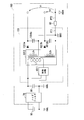
また、図2には、絶縁型DC-DCコンバータ101と共に、低電圧電源60と、ノイズフィルタ70と、コンデンサ80と、ゼロオーム抵抗90と、グラウンドGNDCのパターン配線PT1と、グラウンドGNDHのパターン配線PT2とが示されている。
低電圧電源60は、図1に示されていない、ノイズを除去するためのノイズフィルタ70とコンデンサ80とを介して、絶縁型DC-DCコンバータ101へ直流電圧を出力している。
また、図2には、絶縁型DC-DCコンバータ101と共に、低電圧電源60と、ノイズフィルタ70と、コンデンサ80と、ゼロオーム抵抗90と、グラウンドGNDCのパターン配線PT1と、グラウンドGNDHのパターン配線PT2とが示されている。
低電圧電源60は、図1に示されていない、ノイズを除去するためのノイズフィルタ70とコンデンサ80とを介して、絶縁型DC-DCコンバータ101へ直流電圧を出力している。
制御回路1011は、後述する絶縁トランス1012の一次側コイルL1に流す電流を制御する。
絶縁トランス1012は、一次側コイルL1と、二次側コイルL2aと、二次側コイルL2bと、を備える。
一次側コイルL1は、制御回路1011による制御に基づく電流を流す。
絶縁トランス1012の二次側コイルL2aは、電磁誘導によって、一次側コイルL1と二次側コイルL2aとの巻線数比、及び、一次側コイルL1に流れる電流に応じた電流を流す。
一次側コイルL1は、制御回路1011による制御に基づく電流を流す。
絶縁トランス1012の二次側コイルL2aは、電磁誘導によって、一次側コイルL1と二次側コイルL2aとの巻線数比、及び、一次側コイルL1に流れる電流に応じた電流を流す。
整流回路1013aは、二次側コイルL2aが流す電流を整流する。
整流回路1013aは、例えば、ダイオードである。
整流回路1013aは、例えば、ダイオードである。
平滑回路1014aは、整流回路1013aから流れる電流を用いて充電する。また、平滑回路1014aは、整流回路1013aから流れる電流が無く、絶縁型DC-DCコンバータ101の負荷が電流を必要とする場合に絶縁型DC-DCコンバータ101の負荷に対して放電する。
平滑回路1014aは、例えば、コンデンサである。
平滑回路1014aは、例えば、コンデンサである。
同様に、絶縁トランス1012の二次側コイルL2bは、一次側コイルL1と二次側コイルL2aとの巻線数比、及び、一次側コイルL1に流れる電流に応じた電流を流す。
整流回路1013bは、二次側コイルL2bが流す電流を整流する。
整流回路1013bは、例えば、ダイオードである。
整流回路1013bは、例えば、ダイオードである。
平滑回路1014bは、整流回路1013bから流れる電流を用いて充電する。また、平滑回路1014bは、整流回路1013bから流れる電流が無く、絶縁型DC-DCコンバータ101の負荷が電流を必要とする場合に絶縁型DC-DCコンバータ101の負荷に対して放電する。
平滑回路1014bは、例えば、コンデンサである。
平滑回路1014bは、例えば、コンデンサである。
回路基板100が備えるグラウンドGNDCのパターン配線PT1は、図2において、二次側コイルL2aの一端、平滑回路1014aの一端、二次側コイルL2bの一端、平滑回路1014bの一端、ゼロオーム抵抗90の一端のそれぞれに接続された領域である。
回路基板100が備えるグラウンドGNDHのパターン配線PT2は、図2において、ゼロオーム抵抗90の他端に接続された領域である。
グラウンドGNDCのパターン配線PT1とグラウンドGNDHのパターン配線PT2とは、図2に示すように、回路基板100上の1か所でゼロオーム抵抗90により接続されている。
具体的には、グラウンドGNDCのパターン配線PT1は、図3に示すように、グラウンドGNDHのパターン配線PT2、及び、グラウンドGNDLのパターン配線PT3のそれぞれから独立している。グラウンドGNDCのパターン配線PT1とグラウンドGNDHのパターン配線PT2のそれぞれは、図4に示すように、ゼロオーム抵抗90と自身のグラウンドとを接続するための接続領域200(例えば、パッドやランドなど)を有している。ゼロオーム抵抗90は、グラウンドGNDCのパターン配線PT1とグラウンドGNDHのパターン配線PT2のそれぞれの接続領域200と半田付けされている。このように、グラウンドGNDCのパターン配線PT1とグラウンドGNDHのパターン配線PT2とは、回路基板100上の1か所でゼロオーム抵抗90により接続されている。
具体的には、グラウンドGNDCのパターン配線PT1は、図3に示すように、グラウンドGNDHのパターン配線PT2、及び、グラウンドGNDLのパターン配線PT3のそれぞれから独立している。グラウンドGNDCのパターン配線PT1とグラウンドGNDHのパターン配線PT2のそれぞれは、図4に示すように、ゼロオーム抵抗90と自身のグラウンドとを接続するための接続領域200(例えば、パッドやランドなど)を有している。ゼロオーム抵抗90は、グラウンドGNDCのパターン配線PT1とグラウンドGNDHのパターン配線PT2のそれぞれの接続領域200と半田付けされている。このように、グラウンドGNDCのパターン配線PT1とグラウンドGNDHのパターン配線PT2とは、回路基板100上の1か所でゼロオーム抵抗90により接続されている。
このように、グラウンドGNDCのパターン配線PT1とグラウンドGNDHのパターン配線PT2とが回路基板100上の1か所でゼロオーム抵抗90により接続される。これにより、圧縮機制御回路11は、絶縁型DC-DCコンバータ101で発生したメガヘルツのオーダの周波数帯のノイズが、インバータ制御回路104を介してインバータ主回路105へ伝播する経路を減らす。圧縮機制御回路11は、絶縁型DC-DCコンバータ101で発生したメガヘルツのオーダの周波数帯のノイズが高電圧電源40の系統に回り込むことを防ぐ。圧縮機制御回路11は、高電圧電源40の系統と低電圧電源60の系統とによる回路におけるループの形成を防止することができる。その結果、圧縮機制御回路11は、車両1において、簡易な構成で電磁ノイズの放出を防止することができる。
なお、グラウンドGNDCのパターン配線PT1とグラウンドGNDHのパターン配線PT2との接続は、ゼロオーム抵抗90により行われるものに限定しない。例えば、グラウンドGNDCのパターン配線PT1とグラウンドGNDHのパターン配線PT2との接続は、抵抗値の小さいジャンパー線などにより行われてもよい。
以上、本発明の第一の実施形態による車両1について説明した。
本発明の第一の実施形態による車両1において、圧縮機制御回路11は、絶縁型DC-DCコンバータ101と、インバータ制御回路104と、回路基板100と、を備える。
絶縁型DC-DCコンバータ101は、一次側回路(入力側)と二次側回路(出力側)とが絶縁されている。インバータ制御回路104は、絶縁型DC-DCコンバータ101から電力が供給される。回路基板100は、絶縁型DC-DCコンバータ101及びインバータ制御回路104を搭載する。回路基板100は、グラウンドGNDCのパターン配線PT1を備える。グラウンドGNDCは、一次側回路が接続される低電圧電源60の系統のグラウンドGNDLのパターン配線PT3、及び、インバータ制御回路104が接続される高電圧電源40の系統のグラウンドGNDHのパターン配線PT2から独立している。グラウンドGNDCは、回路基板100上の1か所のみで高電圧電源40の系統のグラウンドGNDHのパターン配線PT2と接続されている。グラウンドGNDCは、二次側回路が接続されている。
具体的には、回路基板100上の1か所は、ゼロオーム抵抗やジャンパー線などの短絡用素子を用いて接続されている。
このようにすれば、圧縮機制御回路11は、車両1において、簡易な構成で電磁ノイズの放出を防止することができる。
本発明の第一の実施形態による車両1において、圧縮機制御回路11は、絶縁型DC-DCコンバータ101と、インバータ制御回路104と、回路基板100と、を備える。
絶縁型DC-DCコンバータ101は、一次側回路(入力側)と二次側回路(出力側)とが絶縁されている。インバータ制御回路104は、絶縁型DC-DCコンバータ101から電力が供給される。回路基板100は、絶縁型DC-DCコンバータ101及びインバータ制御回路104を搭載する。回路基板100は、グラウンドGNDCのパターン配線PT1を備える。グラウンドGNDCは、一次側回路が接続される低電圧電源60の系統のグラウンドGNDLのパターン配線PT3、及び、インバータ制御回路104が接続される高電圧電源40の系統のグラウンドGNDHのパターン配線PT2から独立している。グラウンドGNDCは、回路基板100上の1か所のみで高電圧電源40の系統のグラウンドGNDHのパターン配線PT2と接続されている。グラウンドGNDCは、二次側回路が接続されている。
具体的には、回路基板100上の1か所は、ゼロオーム抵抗やジャンパー線などの短絡用素子を用いて接続されている。
このようにすれば、圧縮機制御回路11は、車両1において、簡易な構成で電磁ノイズの放出を防止することができる。
<第二の実施形態>
本発明の第二の実施形態による空気調和システムの構成について説明する。
本発明の第二の実施形態による車両1は、図1で示した本発明の第一の実施形態による車両1と同様に、走行用モータ2と、空気調和システム3と、を備える。
本発明の第二の実施形態による空気調和システムの構成について説明する。
本発明の第二の実施形態による車両1は、図1で示した本発明の第一の実施形態による車両1と同様に、走行用モータ2と、空気調和システム3と、を備える。
走行用モータ2は、車両1を走行させるためのモータである。
走行用モータ2は、高電圧電源40から電力を受けて動作する。
走行用モータ2は、高電圧電源40から電力を受けて動作する。
空気調和システム3は、図1で示した本発明の第一の実施形態による空気調和システム3と同様に、インバータ一体型電動圧縮装置10と、熱交換器系機器20と、車両空調コントローラ30と、高電圧電源40と、車両用絶縁型DC-DCコンバータ50と、低電圧電源60と、を備える。
インバータ一体型電動圧縮装置10は、圧縮機制御回路11と、圧縮機モータ106と、圧縮機107と、を備える。
圧縮機制御回路11は、回路基板100と、絶縁型DC-DCコンバータ101と、通信回路102と、絶縁素子103と、インバータ制御回路104と、インバータ主回路105と、を備える。
回路基板100は、高電圧電源40の系統のグラウンドGNDHのパターン配線PT2と、低電圧電源60の系統のグラウンドGNDLのパターン配線PT3と、グラウンドGNDHのパターン配線PT2及びグラウンドGNDLのパターン配線PT3のそれぞれから独立したグラウンドGNDCのパターン配線PT1と、を備える。
グラウンドGNDCのパターン配線PT1は、グラウンドGNDHのパターン配線PT2と回路基板100上の1か所でのみ接続されている。
なお、回路基板100には、絶縁型DC-DCコンバータ101と、通信回路102と、絶縁素子103と、インバータ制御回路104と、インバータ主回路105と、が搭載されている。
グラウンドGNDCのパターン配線PT1は、グラウンドGNDHのパターン配線PT2と回路基板100上の1か所でのみ接続されている。
なお、回路基板100には、絶縁型DC-DCコンバータ101と、通信回路102と、絶縁素子103と、インバータ制御回路104と、インバータ主回路105と、が搭載されている。
次に、本発明の第二の実施形態におけるグラウンドGNDCのパターン配線PT1がグラウンドGNDHのパターン配線PT2と回路基板100上の1か所でのみ接続されていることについて、詳しく説明する。
本発明の第二の実施形態による絶縁型DC-DCコンバータ101は、図5に示すように、制御回路1011と、絶縁トランス1012と、整流回路1013aと、整流回路1013bと、平滑回路1014aと、平滑回路1014bと、を備える。
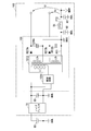
また、図5には、絶縁型DC-DCコンバータ101と共に、低電圧電源60と、ノイズフィルタ70と、コンデンサ80と、インダクタ91(第1ノイズフィルタ)と、コンデンサ92と、コンデンサ93と、グラウンドGNDCのパターン配線PT1と、グラウンドGNDHのパターン配線PT2とが示されている。
低電圧電源60は、ノイズを除去するためのノイズフィルタ70とコンデンサ80とを介して、絶縁型DC-DCコンバータ101へ直流電圧を出力している。
低電圧電源60は、ノイズを除去するためのノイズフィルタ70とコンデンサ80とを介して、絶縁型DC-DCコンバータ101へ直流電圧を出力している。
インダクタ91は、グラウンドGNDCのパターン配線PT1とグラウンドGNDHのパターン配線PT2との間に設けられている。
インダクタ91は、コンデンサ92及びコンデンサ93と共にノイズフィルタを構成する。
インダクタ91は、例えば、チップフェライトビーズインダクタである。
インダクタ91は、コンデンサ92及びコンデンサ93と共にノイズフィルタを構成する。
インダクタ91は、例えば、チップフェライトビーズインダクタである。
コンデンサ92は、グラウンドGNDCのパターン配線PT1とグラウンドGNDLとの間に設けられている。
コンデンサ93は、グラウンドGNDHのパターン配線PT2とグラウンドGNDLとの間に設けられている。
コンデンサ93は、グラウンドGNDHのパターン配線PT2とグラウンドGNDLとの間に設けられている。
回路基板100が備えるグラウンドGNDCのパターン配線PT1は、二次側コイルL2aの一端、平滑回路1014aの一端、二次側コイルL2bの一端、平滑回路1014bの一端、コンデンサ92の一端、インダクタ91の一端のそれぞれに接続された領域である。
回路基板100が備えるグラウンドGNDHのパターン配線PT2は、コンデンサ93の一端、インダクタ91の他端のそれぞれに接続された領域である。
コンデンサ92の他端、コンデンサ93の他端のそれぞれは、グラウンドGNDLに間接的に、または、直接的に接続されるパターン配線に接続される。
グラウンドGNDCのパターン配線PT1とグラウンドGNDHのパターン配線PT2とは、図2で示した回路基板100上の1か所でゼロオーム抵抗90により接続されている場合と同様に、図5に示すように、回路基板100上の1か所でインダクタ91により接続されている。
具体的には、グラウンドGNDCのパターン配線PT1は、図6に示すように、グラウンドGNDHのパターン配線PT2、及び、グラウンドGNDLのパターン配線PT3のそれぞれから独立している。また、グラウンドGNDCのパターン配線PT1は、金属ネジ等を介してグラウンドGNDLのパターン配線PT3に接続されたパターン配線PT6にコンデンサ92を介して接続される。また、グラウンドGNDHのパターン配線PT2は、金属ネジ等を介してグラウンドGNDLのパターン配線PT3に接続されたパターン配線PT6にコンデンサ93を介して接続される。グラウンドGNDCのパターン配線PT1とグラウンドGNDHのパターン配線PT2のそれぞれは、図7に示すように、インダクタ91と自身のグラウンドとを接続するための接続領域200(例えば、パッドやランドなど)を有している。インダクタ91は、グラウンドGNDCのパターン配線PT1とグラウンドGNDHのパターン配線PT2のそれぞれの接続領域200と半田付けされている。このように、グラウンドGNDCのパターン配線PT1とグラウンドGNDHのパターン配線PT2とは、回路基板100上の1か所でインダクタ91により接続されている。
具体的には、グラウンドGNDCのパターン配線PT1は、図6に示すように、グラウンドGNDHのパターン配線PT2、及び、グラウンドGNDLのパターン配線PT3のそれぞれから独立している。また、グラウンドGNDCのパターン配線PT1は、金属ネジ等を介してグラウンドGNDLのパターン配線PT3に接続されたパターン配線PT6にコンデンサ92を介して接続される。また、グラウンドGNDHのパターン配線PT2は、金属ネジ等を介してグラウンドGNDLのパターン配線PT3に接続されたパターン配線PT6にコンデンサ93を介して接続される。グラウンドGNDCのパターン配線PT1とグラウンドGNDHのパターン配線PT2のそれぞれは、図7に示すように、インダクタ91と自身のグラウンドとを接続するための接続領域200(例えば、パッドやランドなど)を有している。インダクタ91は、グラウンドGNDCのパターン配線PT1とグラウンドGNDHのパターン配線PT2のそれぞれの接続領域200と半田付けされている。このように、グラウンドGNDCのパターン配線PT1とグラウンドGNDHのパターン配線PT2とは、回路基板100上の1か所でインダクタ91により接続されている。
このように、グラウンドGNDCのパターン配線PT1とグラウンドGNDHのパターン配線PT2とが回路基板100上の1か所でインダクタ91により接続される。これにより、圧縮機制御回路11は、絶縁型DC-DCコンバータ101で発生したメガヘルツのオーダの周波数帯のノイズが、インバータ制御回路104を介してインバータ主回路105へ伝播する経路を減らす。圧縮機制御回路11は、絶縁型DC-DCコンバータ101で発生したメガヘルツのオーダの周波数帯のノイズが高電圧電源40の系統に回り込むことを防ぐ。圧縮機制御回路11は、高電圧電源40の系統と低電圧電源60の系統とによる回路におけるループの形成を防止することができる。その結果、圧縮機制御回路11は、車両1において、簡易な構成で電磁ノイズの放出を防止することができる。
以上、本発明の第二の実施形態による車両1について説明した。
本発明の第二の実施形態による車両1において、圧縮機制御回路11は、絶縁型DC-DCコンバータ101と、インバータ制御回路104と、回路基板100と、を備える。
絶縁型DC-DCコンバータ101は、一次側回路(入力側)と二次側回路(出力側)とが絶縁されている。インバータ制御回路104は、絶縁型DC-DCコンバータ101から電力が供給される。回路基板100は、絶縁型DC-DCコンバータ101及びインバータ制御回路104を搭載する。回路基板100は、グラウンドGNDCのパターン配線PT1を備える。グラウンドGNDCが、一次側回路が接続される低電圧電源60の系統のグラウンドGNDLのパターン配線PT3、及び、インバータ制御回路104が接続される高電圧電源40の系統のグラウンドGNDHのパターン配線PT2から独立している。グラウンドGNDCは、回路基板100上の1か所のみで高電圧電源40の系統のグラウンドGNDHのパターン配線PT2と接続されている。グラウンドGNDCは、二次側回路が接続されている。
具体的には、例えば、回路基板上の1か所は、インダクタ91などの第1ノイズフィルタを用いて接続されている。
このようにすれば、圧縮機制御回路11は、車両1において、簡易な構成で電磁ノイズの放出を防止することができる。
本発明の第二の実施形態による車両1において、圧縮機制御回路11は、絶縁型DC-DCコンバータ101と、インバータ制御回路104と、回路基板100と、を備える。
絶縁型DC-DCコンバータ101は、一次側回路(入力側)と二次側回路(出力側)とが絶縁されている。インバータ制御回路104は、絶縁型DC-DCコンバータ101から電力が供給される。回路基板100は、絶縁型DC-DCコンバータ101及びインバータ制御回路104を搭載する。回路基板100は、グラウンドGNDCのパターン配線PT1を備える。グラウンドGNDCが、一次側回路が接続される低電圧電源60の系統のグラウンドGNDLのパターン配線PT3、及び、インバータ制御回路104が接続される高電圧電源40の系統のグラウンドGNDHのパターン配線PT2から独立している。グラウンドGNDCは、回路基板100上の1か所のみで高電圧電源40の系統のグラウンドGNDHのパターン配線PT2と接続されている。グラウンドGNDCは、二次側回路が接続されている。
具体的には、例えば、回路基板上の1か所は、インダクタ91などの第1ノイズフィルタを用いて接続されている。
このようにすれば、圧縮機制御回路11は、車両1において、簡易な構成で電磁ノイズの放出を防止することができる。
<第三の実施形態>
本発明の第三の実施形態による空気調和システムの構成について説明する。
本発明の第三の実施形態による車両1は、図1で示した本発明の第一の実施形態による車両1と同様に、走行用モータ2と、空気調和システム3と、を備える。
本発明の第三の実施形態による空気調和システムの構成について説明する。
本発明の第三の実施形態による車両1は、図1で示した本発明の第一の実施形態による車両1と同様に、走行用モータ2と、空気調和システム3と、を備える。
走行用モータ2は、車両1を走行させるためのモータである。
走行用モータ2は、高電圧電源40から電力を受けて動作する。
走行用モータ2は、高電圧電源40から電力を受けて動作する。
空気調和システム3は、図1で示した本発明の第一の実施形態による空気調和システム3と同様に、インバータ一体型電動圧縮装置10と、熱交換器系機器20と、車両空調コントローラ30と、高電圧電源40と、車両用絶縁型DC-DCコンバータ50と、低電圧電源60と、を備える。
インバータ一体型電動圧縮装置10は、圧縮機制御回路11と、圧縮機モータ106と、圧縮機107と、を備える。
圧縮機制御回路11は、回路基板100と、絶縁型DC-DCコンバータ101と、通信回路102と、絶縁素子103と、インバータ制御回路104と、インバータ主回路105と、を備える。
回路基板100は、高電圧電源40の系統のグラウンドGNDHのパターン配線PT2と、低電圧電源60の系統のグラウンドGNDLのパターン配線PT3と、グラウンドGNDHのパターン配線PT2及びグラウンドGNDLのパターン配線PT3のそれぞれから独立したグラウンドGNDCのパターン配線PT1と、を備える。
グラウンドGNDCのパターン配線PT1は、グラウンドGNDHのパターン配線PT2と回路基板100上の1か所でのみ接続されている。
なお、回路基板100には、絶縁型DC-DCコンバータ101と、通信回路102と、絶縁素子103と、インバータ制御回路104と、インバータ主回路105と、が搭載されている。
グラウンドGNDCのパターン配線PT1は、グラウンドGNDHのパターン配線PT2と回路基板100上の1か所でのみ接続されている。
なお、回路基板100には、絶縁型DC-DCコンバータ101と、通信回路102と、絶縁素子103と、インバータ制御回路104と、インバータ主回路105と、が搭載されている。
次に、本発明の第三の実施形態におけるグラウンドGNDCのパターン配線PT1がグラウンドGNDHのパターン配線PT2と回路基板100上の1か所でのみ接続されていることについて、詳しく説明する。
本発明の第三の実施形態による絶縁型DC-DCコンバータ101は、図8に示すように、制御回路1011と、絶縁トランス1012と、整流回路1013aと、整流回路1013bと、平滑回路1014aと、平滑回路1014bと、を備える。
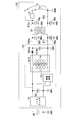
また、図8には、絶縁型DC-DCコンバータ101と共に、低電圧電源60と、ノイズフィルタ70と、コンデンサ80と、インダクタ91と、コンデンサ92と、コンデンサ93と、インダクタ94a(第2ノイズフィルタのうちの1つ)と、インダクタ94b(第2ノイズフィルタのうちの1つ)と、コンデンサ95aと、コンデンサ95bと、コンデンサ96aと、コンデンサ96bと、グラウンドGNDCのパターン配線PT1と、グラウンドGNDHのパターン配線PT2とが示されている。
低電圧電源60は、ノイズを除去するためのノイズフィルタ70とコンデンサ80とを介して、絶縁型DC-DCコンバータ101へ直流電圧を出力している。
低電圧電源60は、ノイズを除去するためのノイズフィルタ70とコンデンサ80とを介して、絶縁型DC-DCコンバータ101へ直流電圧を出力している。
インダクタ94aは、インダクタ91と同様のインダクタである。
インダクタ94aは、コンデンサ95a及びコンデンサ96aと共にノイズフィルタを構成する。
インダクタ94aは、絶縁型DC-DCコンバータ101からグラウンドGNDHに接続されるインバータ制御回路104などの負荷へ電力を供給する経路において、絶縁型DC-DCコンバータ101側のパターン配線PT4aと負荷側のパターン配線PT5aとの間に設けられている。
インダクタ94aは、インダクタ91と共にコモンモード電流による磁束は足し合わされてインダクタに働き、ディファレンシャル電流による磁束は打ち消されてインダクタに働くノイズを除去するコモンモードフィルタを構成する。
インダクタ94aは、コンデンサ95a及びコンデンサ96aと共にノイズフィルタを構成する。
インダクタ94aは、絶縁型DC-DCコンバータ101からグラウンドGNDHに接続されるインバータ制御回路104などの負荷へ電力を供給する経路において、絶縁型DC-DCコンバータ101側のパターン配線PT4aと負荷側のパターン配線PT5aとの間に設けられている。
インダクタ94aは、インダクタ91と共にコモンモード電流による磁束は足し合わされてインダクタに働き、ディファレンシャル電流による磁束は打ち消されてインダクタに働くノイズを除去するコモンモードフィルタを構成する。
コンデンサ95aは、グラウンドGNDLと絶縁型DC-DCコンバータ101側のパターン配線PT4aとの間に設けられている。
コンデンサ96aは、グラウンドGNDLと負荷側のパターン配線PT5aとの間に設けられている。
同様に、インダクタ94bは、インダクタ91と同様のインダクタである。
インダクタ94bは、コンデンサ95b及びコンデンサ96bと共にノイズフィルタを構成する。
インダクタ94bは、絶縁型DC-DCコンバータ101からグラウンドGNDHに接続されるインバータ制御回路104などの負荷へ電力を供給する経路において、絶縁型DC-DCコンバータ101側のパターン配線PT4bと負荷側のパターン配線PT5bとの間に設けられている。
インダクタ94bは、インダクタ91と共にコモンモードフィルタを構成する。
インダクタ94bは、コンデンサ95b及びコンデンサ96bと共にノイズフィルタを構成する。
インダクタ94bは、絶縁型DC-DCコンバータ101からグラウンドGNDHに接続されるインバータ制御回路104などの負荷へ電力を供給する経路において、絶縁型DC-DCコンバータ101側のパターン配線PT4bと負荷側のパターン配線PT5bとの間に設けられている。
インダクタ94bは、インダクタ91と共にコモンモードフィルタを構成する。
コンデンサ95bは、グラウンドGNDLと絶縁型DC-DCコンバータ101側のパターン配線PT4bとの間に設けられている。
コンデンサ96bは、グラウンドGNDLと負荷側のパターン配線PT5bとの間に設けられている。
回路基板100が備えるグラウンドGNDCのパターン配線PT1は、二次側コイルL2aの一端、平滑回路1014aの一端、二次側コイルL2bの一端、平滑回路1014bの一端、コンデンサ92の両端、インダクタ91の一端のそれぞれに接続された領域である。
回路基板100が備えるグラウンドGNDHのパターン配線PT2は、コンデンサ93の両端、インダクタ91の他端、コンデンサ96aの一端、コンデンサ96bの一端のそれぞれに接続された領域である。
回路基板100が備える絶縁型DC-DCコンバータ101側のパターン配線PT4aは、整流回路1013aの一端、平滑回路1014aの他端、コンデンサ95aの一端、インダクタ94aの一端のそれぞれに接続された領域である。
回路基板100が備える負荷側のパターン配線PT5aは、インダクタ94aの他端、コンデンサ96aの一端のそれぞれに接続された領域である。
回路基板100が備える絶縁型DC-DCコンバータ101側のパターン配線PT4bは、整流回路1013bの一端、平滑回路1014bの他端、コンデンサ95bの一端、インダクタ94bの一端のそれぞれに接続された領域である。
回路基板100が備える負荷側のパターン配線PT5bは、インダクタ94bの他端、コンデンサ96bの一端のそれぞれに接続された領域である。
コンデンサ95aの他端、コンデンサ95bの他端、コンデンサ96aの他端、コンデンサ96bの他端のそれぞれは、グラウンドGNDLに間接的に、または、直接的に接続されるパターン配線に接続される。
グラウンドGNDCのパターン配線PT1とグラウンドGNDHのパターン配線PT2とは、図8に示すように、図5で示した本発明の第二の実施形態における接続と同様に、回路基板100上の1か所でインダクタ94aにより接続されている。
絶縁型DC-DCコンバータ101側のパターン配線PT4aと負荷側のパターン配線PT5aとは、図8に示すように、回路基板100上の1か所でインダクタ91により接続されている。
具体的には、絶縁型DC-DCコンバータ101側のパターン配線PT4aと負荷側のパターン配線PT5aのそれぞれは、図9に示すように、インダクタ94aと自身のパターン配線とを接続するための接続領域200(例えば、パッドやランドなど)を有している。インダクタ94aは、絶縁型DC-DCコンバータ101側のパターン配線PT4aと負荷側のパターン配線PT5aのそれぞれの接続領域200と半田付けされている。このように、絶縁型DC-DCコンバータ101側のパターン配線PT4aと負荷側のパターン配線PT5aとは、回路基板100上の1か所でインダクタ94aにより接続されている。
具体的には、絶縁型DC-DCコンバータ101側のパターン配線PT4aと負荷側のパターン配線PT5aのそれぞれは、図9に示すように、インダクタ94aと自身のパターン配線とを接続するための接続領域200(例えば、パッドやランドなど)を有している。インダクタ94aは、絶縁型DC-DCコンバータ101側のパターン配線PT4aと負荷側のパターン配線PT5aのそれぞれの接続領域200と半田付けされている。このように、絶縁型DC-DCコンバータ101側のパターン配線PT4aと負荷側のパターン配線PT5aとは、回路基板100上の1か所でインダクタ94aにより接続されている。
同様に、絶縁型DC-DCコンバータ101側のパターン配線PT4bと負荷側のパターン配線PT5bとは、回路基板100上の1か所でインダクタ94bにより接続されている。
このように、圧縮機制御回路11は、グラウンド側と負荷への電力供給側のそれぞれにノイズフィルタを設けてコモンモードフィルタを構成している。これにより、絶縁型DC-DCコンバータ101で発生したメガヘルツのオーダの周波数帯のノイズが、インバータ制御回路104を介してインバータ主回路105へ伝播する経路を減らす。圧縮機制御回路11は、絶縁型DC-DCコンバータ101で発生したメガヘルツのオーダの周波数帯のノイズが高電圧電源40の系統に回り込むことを防ぐ。圧縮機制御回路11は、高電圧電源40の系統と低電圧電源60の系統とによる回路におけるループの形成を防止することができる。その結果、圧縮機制御回路11は、車両1において、簡易な構成で電磁ノイズの放出を防止することができる。
以上、本発明の第三の実施形態による車両1について説明した。
本発明の第三の実施形態による車両1において、圧縮機制御回路11は、絶縁型DC-DCコンバータ101と、インバータ制御回路104と、回路基板100と、を備える。
絶縁型DC-DCコンバータ101は、一次側回路(入力側)と二次側回路(出力側)とが絶縁されている。インバータ制御回路104は、絶縁型DC-DCコンバータ101から電力が供給される。回路基板100は、絶縁型DC-DCコンバータ101及びインバータ制御回路104を搭載する。回路基板100は、グラウンドGNDCのパターン配線PT1を備える。グラウンドGNDCは、一次側回路が接続される低電圧電源60の系統のグラウンドGNDLのパターン配線PT3、及び、インバータ制御回路104が接続される高電圧電源40の系統のグラウンドGNDHのパターン配線PT2から独立している。グラウンドGNDCは、回路基板100上の1か所のみで高電圧電源40の系統のグラウンドGNDHのパターン配線PT2と接続されている。グラウンドGNDCは、二次側回路が接続されている。
具体的には、例えば、回路基板上の1か所は、インダクタ91などの第1ノイズフィルタを用いて接続されている。また、回路基板上の1か所は、さらに、絶縁型DC-DCコンバータ101からインバータ制御回路104へ電力を供給する経路において絶縁型DC-DCコンバータ101とインバータ制御回路104との間に第1ノイズフィルタと同様の第2ノイズフィルタが設けられている。
このようにすれば、圧縮機制御回路11は、車両1において、簡易な構成で電磁ノイズの放出を防止することができる。
本発明の第三の実施形態による車両1において、圧縮機制御回路11は、絶縁型DC-DCコンバータ101と、インバータ制御回路104と、回路基板100と、を備える。
絶縁型DC-DCコンバータ101は、一次側回路(入力側)と二次側回路(出力側)とが絶縁されている。インバータ制御回路104は、絶縁型DC-DCコンバータ101から電力が供給される。回路基板100は、絶縁型DC-DCコンバータ101及びインバータ制御回路104を搭載する。回路基板100は、グラウンドGNDCのパターン配線PT1を備える。グラウンドGNDCは、一次側回路が接続される低電圧電源60の系統のグラウンドGNDLのパターン配線PT3、及び、インバータ制御回路104が接続される高電圧電源40の系統のグラウンドGNDHのパターン配線PT2から独立している。グラウンドGNDCは、回路基板100上の1か所のみで高電圧電源40の系統のグラウンドGNDHのパターン配線PT2と接続されている。グラウンドGNDCは、二次側回路が接続されている。
具体的には、例えば、回路基板上の1か所は、インダクタ91などの第1ノイズフィルタを用いて接続されている。また、回路基板上の1か所は、さらに、絶縁型DC-DCコンバータ101からインバータ制御回路104へ電力を供給する経路において絶縁型DC-DCコンバータ101とインバータ制御回路104との間に第1ノイズフィルタと同様の第2ノイズフィルタが設けられている。
このようにすれば、圧縮機制御回路11は、車両1において、簡易な構成で電磁ノイズの放出を防止することができる。
<第四の実施形態>
本発明の第四の実施形態による空気調和システムの構成について説明する。
本発明の第四の実施形態による車両1は、図1で示した本発明の第一の実施形態による車両1と同様に、走行用モータ2と、空気調和システム3と、を備える。
本発明の第四の実施形態による空気調和システムの構成について説明する。
本発明の第四の実施形態による車両1は、図1で示した本発明の第一の実施形態による車両1と同様に、走行用モータ2と、空気調和システム3と、を備える。
走行用モータ2は、車両1を走行させるためのモータである。
走行用モータ2は、高電圧電源40から電力を受けて動作する。
走行用モータ2は、高電圧電源40から電力を受けて動作する。
空気調和システム3は、図1で示した本発明の第一の実施形態による空気調和システム3と同様に、インバータ一体型電動圧縮装置10と、熱交換器系機器20と、車両空調コントローラ30と、高電圧電源40と、車両用絶縁型DC-DCコンバータ50と、低電圧電源60と、を備える。
インバータ一体型電動圧縮装置10は、圧縮機制御回路11と、圧縮機モータ106と、圧縮機107と、を備える。
圧縮機制御回路11は、回路基板100と、絶縁型DC-DCコンバータ101と、通信回路102と、絶縁素子103と、インバータ制御回路104と、インバータ主回路105と、を備える。
回路基板100は、高電圧電源40の系統のグラウンドGNDHのパターン配線PT2と、低電圧電源60の系統のグラウンドGNDLのパターン配線PT3と、グラウンドGNDHのパターン配線PT2及びグラウンドGNDLのパターン配線PT3のそれぞれから独立したグラウンドGNDCのパターン配線PT1と、を備える。
グラウンドGNDCのパターン配線PT1は、グラウンドGNDHのパターン配線PT2と回路基板100上の1か所でのみ接続されている。
なお、回路基板100には、絶縁型DC-DCコンバータ101と、通信回路102と、絶縁素子103と、インバータ制御回路104と、インバータ主回路105と、が搭載されている。
グラウンドGNDCのパターン配線PT1は、グラウンドGNDHのパターン配線PT2と回路基板100上の1か所でのみ接続されている。
なお、回路基板100には、絶縁型DC-DCコンバータ101と、通信回路102と、絶縁素子103と、インバータ制御回路104と、インバータ主回路105と、が搭載されている。
次に、本発明の第四の実施形態におけるグラウンドGNDCのパターン配線PT1がグラウンドGNDHのパターン配線PT2と回路基板100上の1か所でのみ接続されていることについて、詳しく説明する。
本発明の第四の実施形態による絶縁型DC-DCコンバータ101は、図10に示すように、制御回路1011と、絶縁トランス1012と、整流回路1013aと、平滑回路1014aと、を備える。
また、図10には、絶縁型DC-DCコンバータ101と共に、低電圧電源60と、ノイズフィルタ70と、コンデンサ80と、コモンモードフィルタ97と、コンデンサ98aと、コンデンサ98bと、コンデンサ99bと、コンデンサ99bと、グラウンドGNDCのパターン配線PT1と、グラウンドGNDHのパターン配線PT2と、が示されている。
低電圧電源60は、ノイズを除去するためのノイズフィルタ70とコンデンサ80とを介して、絶縁型DC-DCコンバータ101へ直流電圧を出力している。
低電圧電源60は、ノイズを除去するためのノイズフィルタ70とコンデンサ80とを介して、絶縁型DC-DCコンバータ101へ直流電圧を出力している。
コモンモードフィルタ97は、第1チョークコイルL11と第2チョークコイルL12とを備える。コモンモードフィルタ97は、コモンモード電流による磁束は足し合わされてインダクタに働き、ディファレンシャル電流による磁束は打ち消されてインダクタに働くノイズを除去するノイズを除去する。
第1チョークコイルL11は、グラウンドGNDCのパターン配線PT1とグラウンドGNDHのパターン配線PT2との間に設けられている。
第2チョークコイルL12は、絶縁型DC-DCコンバータ101からグラウンドGNDHに接続されるインバータ制御回路104などの負荷へ電力を供給する経路において、絶縁型DC-DCコンバータ101側のパターン配線PT4aと負荷側のパターン配線PT5aとの間に設けられている。
コンデンサ98aは、グラウンドGNDCのパターン配線PT1とグラウンドGNDLとの間に設けられている。
コンデンサ99aは、グラウンドGNDHのパターン配線PT2とグラウンドGNDLとの間に設けられている。
コンデンサ99aは、グラウンドGNDHのパターン配線PT2とグラウンドGNDLとの間に設けられている。
コンデンサ98bは、グラウンドGNDLと絶縁型DC-DCコンバータ101側のパターン配線PT4aとの間に設けられている。
コンデンサ99bは、グラウンドGNDLと負荷側のパターン配線PT5aとの間に設けられている。
回路基板100が備えるグラウンドGNDCのパターン配線PT1は、二次側コイルL2aの一端、平滑回路1014aの一端、二次側コイルL2bの一端、コンデンサ98aの一端、第1チョークコイルL11の一端のそれぞれに接続された領域である。
回路基板100が備えるグラウンドGNDHのパターン配線PT2は、第1チョークコイルL11の他端、コンデンサ99aの一端のそれぞれに接続された領域である。
回路基板100が備える絶縁型DC-DCコンバータ101側のパターン配線PT4aは、整流回路1013aの一端、平滑回路1014aの他端、コンデンサ98bの一端、第2チョークコイルL12の一端のそれぞれに接続された領域である。
回路基板100が備える負荷側のパターン配線PT5aは、第2チョークコイルL12の他端端、コンデンサ99bの一端のそれぞれに接続された領域である。
コンデンサ98aの他端、コンデンサ98bの他端、コンデンサ99aの他端、コンデンサ99bの他端のそれぞれは、グラウンドGNDLに間接的に、または、直接的に接続されるパターン配線に接続される。
なお、コンデンサ98a、98b、99a、99bの静電容量値によって、コモンモードフィルタのカットオフ周波数が決定される。
グラウンドGNDCのパターン配線PT1とグラウンドGNDHのパターン配線PT2とは、図10に示すように、回路基板100上の1か所でコモンモードフィルタ97により接続されている。
また、絶縁型DC-DCコンバータ101側のパターン配線PT4aと負荷側のパターン配線PT5aとは、図10に示すように、回路基板100上の1か所でコモンモードフィルタ97により接続されている。
具体的には、グラウンドGNDCのパターン配線PT1、グラウンドGNDHのパターン配線PT2、絶縁型DC-DCコンバータ101側のパターン配線PT4a、負荷側のパターン配線PT5aのそれぞれは、図11に示すように、コモンモードフィルタ97と自身のパターン配線とを接続するための接続領域200(例えば、パッドやランドなど)を有している。コモンモードフィルタ97は、グラウンドGNDCのパターン配線PT1とグラウンドGNDHのパターン配線PT2のそれぞれの接続領域200と半田付けされている。このように、グラウンドGNDCのパターン配線PT1とグラウンドGNDHのパターン配線PT2とは、回路基板100上の1か所でコモンモードフィルタ97により接続されている。
また、コモンモードフィルタ97は、絶縁型DC-DCコンバータ101側のパターン配線PT4aと負荷側のパターン配線PT5aのそれぞれの接続領域200と半田付けされている。このように、絶縁型DC-DCコンバータ101側のパターン配線PT4aと負荷側のパターン配線PT5aとは、回路基板100上の1か所でコモンモードフィルタ97により接続されている。
また、絶縁型DC-DCコンバータ101側のパターン配線PT4aと負荷側のパターン配線PT5aとは、図10に示すように、回路基板100上の1か所でコモンモードフィルタ97により接続されている。
具体的には、グラウンドGNDCのパターン配線PT1、グラウンドGNDHのパターン配線PT2、絶縁型DC-DCコンバータ101側のパターン配線PT4a、負荷側のパターン配線PT5aのそれぞれは、図11に示すように、コモンモードフィルタ97と自身のパターン配線とを接続するための接続領域200(例えば、パッドやランドなど)を有している。コモンモードフィルタ97は、グラウンドGNDCのパターン配線PT1とグラウンドGNDHのパターン配線PT2のそれぞれの接続領域200と半田付けされている。このように、グラウンドGNDCのパターン配線PT1とグラウンドGNDHのパターン配線PT2とは、回路基板100上の1か所でコモンモードフィルタ97により接続されている。
また、コモンモードフィルタ97は、絶縁型DC-DCコンバータ101側のパターン配線PT4aと負荷側のパターン配線PT5aのそれぞれの接続領域200と半田付けされている。このように、絶縁型DC-DCコンバータ101側のパターン配線PT4aと負荷側のパターン配線PT5aとは、回路基板100上の1か所でコモンモードフィルタ97により接続されている。
このように、圧縮機制御回路11は、グラウンド側と負荷への電力供給側にコモンモードフィルタを設けることにより、絶縁型DC-DCコンバータ101で発生したメガヘルツのオーダの周波数帯のノイズが、インバータ制御回路104を介してインバータ主回路105へ伝播する経路を減らす。圧縮機制御回路11は、絶縁型DC-DCコンバータ101で発生したメガヘルツのオーダの周波数帯のノイズが高電圧電源40の系統に回り込むことを防ぐ。圧縮機制御回路11は、高電圧電源40の系統と低電圧電源60の系統とによる回路におけるループの形成を防止することができる。その結果、圧縮機制御回路11は、車両1において、簡易な構成で電磁ノイズの放出を防止することができる。
以上、本発明の第四の実施形態による車両1について説明した。
本発明の第四の実施形態による車両1において、圧縮機制御回路11は、絶縁型DC-DCコンバータ101と、インバータ制御回路104と、回路基板100と、を備える。
絶縁型DC-DCコンバータ101は、一次側回路(入力側)と二次側回路(出力側)とが絶縁されている。インバータ制御回路104は、絶縁型DC-DCコンバータ101から電力が供給される。回路基板100は、絶縁型DC-DCコンバータ101及びインバータ制御回路104を搭載する。回路基板100は、グラウンドGNDCのパターン配線PT1を備える。グラウンドGNDCは、一次側回路が接続される低電圧電源60の系統のグラウンドGNDLのパターン配線PT3、及び、インバータ制御回路104が接続される高電圧電源40の系統のグラウンドGNDHのパターン配線PT2から独立している。グラウンドGNDCは、回路基板100上の1か所のみで高電圧電源40の系統のグラウンドGNDHのパターン配線PT2と接続されている。グラウンドGNDCはm二次側回路が接続されている。
具体的には、例えば、回路基板100上の1か所は、コモンモードフィルタ97が含む第1チョークコイルL11を用いて接続され、かつ、絶縁型DC-DCコンバータ101からインバータ制御回路104へ電力を供給する経路において絶縁型DC-DCコンバータ101とインバータ制御回路104との間に第2チョークコイルL12が設けられている。
このようにすれば、圧縮機制御回路11は、車両1において、簡易な構成で電磁ノイズの放出を防止することができる。
本発明の第四の実施形態による車両1において、圧縮機制御回路11は、絶縁型DC-DCコンバータ101と、インバータ制御回路104と、回路基板100と、を備える。
絶縁型DC-DCコンバータ101は、一次側回路(入力側)と二次側回路(出力側)とが絶縁されている。インバータ制御回路104は、絶縁型DC-DCコンバータ101から電力が供給される。回路基板100は、絶縁型DC-DCコンバータ101及びインバータ制御回路104を搭載する。回路基板100は、グラウンドGNDCのパターン配線PT1を備える。グラウンドGNDCは、一次側回路が接続される低電圧電源60の系統のグラウンドGNDLのパターン配線PT3、及び、インバータ制御回路104が接続される高電圧電源40の系統のグラウンドGNDHのパターン配線PT2から独立している。グラウンドGNDCは、回路基板100上の1か所のみで高電圧電源40の系統のグラウンドGNDHのパターン配線PT2と接続されている。グラウンドGNDCはm二次側回路が接続されている。
具体的には、例えば、回路基板100上の1か所は、コモンモードフィルタ97が含む第1チョークコイルL11を用いて接続され、かつ、絶縁型DC-DCコンバータ101からインバータ制御回路104へ電力を供給する経路において絶縁型DC-DCコンバータ101とインバータ制御回路104との間に第2チョークコイルL12が設けられている。
このようにすれば、圧縮機制御回路11は、車両1において、簡易な構成で電磁ノイズの放出を防止することができる。
なお、本発明の実施形態においてコンデンサ92、93、95a、95b、96a、96b、98a、98b、99a、99bのそれぞれは、個別部品のコンデンサとして説明したが個別部品のコンデンサに限定するものではない。例えば、コンデンサ92、93、95a、95b、96a、96b、98a、98b、99a、99bのそれぞれは、配線などに起因する寄生素子のコンデンサであってもよい。
なお、本発明の実施形態による空気調和システム3は、自動車、電車、船舶などの車両1に備えられてもよい。
なお、本発明の実施形態における処理は、適切な処理が行われる範囲において、処理の順番が入れ替わってもよい。
本発明における記憶部のそれぞれは、適切な情報の送受信が行われる範囲においてどこに備えられていてもよい。また、記憶部のそれぞれは、適切な情報の送受信が行われる範囲において複数存在しデータを分散して記憶していてもよい。
本発明の実施形態について説明したが、上述の車両1における装置のそれぞれは内部に、コンピュータシステムを有していてもよい。そして、上述した処理の過程は、プログラムの形式でコンピュータ読み取り可能な記録媒体に記憶されており、このプログラムをコンピュータが読み出して実行することによって、上記処理が行われる。ここでコンピュータ読み取り可能な記録媒体とは、磁気ディスク、光磁気ディスク、CD-ROM、DVD-ROM、半導体メモリ等をいう。また、このコンピュータプログラムを通信回線によってコンピュータに配信し、この配信を受けたコンピュータがそのプログラムを実行するようにしてもよい。
また、上記プログラムは、前述した機能の一部を実現してもよい。さらに、上記プログラムは、前述した機能をコンピュータシステムにすでに記録されているプログラムとの組み合わせで実現できるファイル、いわゆる差分ファイル(差分プログラム)であってもよい。
本発明のいくつかの実施形態を説明したが、これらの実施形態は、例であり、発明の範囲を限定しない。これらの実施形態は、発明の要旨を逸脱しない範囲で、種々の追加、省略、置き換え、変更を行ってよい。
圧縮機制御回路及び圧縮装置によれば、車両において、簡易な構成で電磁ノイズの放出を防止することができる。
3 空気調和システム
10 インバータ一体型電動圧縮装置
11 圧縮機制御回路
20 熱交換器系機器
30 車両空調コントローラ
40 高電圧電源
50 車両用絶縁型DC-DCコンバータ
60 低電圧電源
70 ノイズフィルタ
80、92、93、95a、95b、96a、96b、98a、98b、99a、99b コンデンサ
90 ゼロオーム抵抗
91、94a、94b インダクタ
97 コモンモードフィルタ
100・・回路基板
101 絶縁型DC-DCコンバータ
102 通信回路
103 絶縁素子
104 インバータ制御回路
105 インバータ主回路
106 圧縮機モータ
107 圧縮機
200 接続領域
1011 制御回路
1012 絶縁トランス
1013a、1013b 整流回路
1014a、1014b 平滑回路
10 インバータ一体型電動圧縮装置
11 圧縮機制御回路
20 熱交換器系機器
30 車両空調コントローラ
40 高電圧電源
50 車両用絶縁型DC-DCコンバータ
60 低電圧電源
70 ノイズフィルタ
80、92、93、95a、95b、96a、96b、98a、98b、99a、99b コンデンサ
90 ゼロオーム抵抗
91、94a、94b インダクタ
97 コモンモードフィルタ
100・・回路基板
101 絶縁型DC-DCコンバータ
102 通信回路
103 絶縁素子
104 インバータ制御回路
105 インバータ主回路
106 圧縮機モータ
107 圧縮機
200 接続領域
1011 制御回路
1012 絶縁トランス
1013a、1013b 整流回路
1014a、1014b 平滑回路
Claims (9)
- 一次側回路と二次側回路とが絶縁されている絶縁型DC-DCコンバータと、
前記絶縁型DC-DCコンバータから電力が供給されるインバータ制御回路と、
を備え、
前記インバータ制御回路が接続される高電圧電源の系統のグラウンドのパターン配線と、前記一次側回路が接続される低電圧電源の系統のグラウンドのパターン配線、及び、前記インバータ制御回路が接続される高電圧電源の系統のグラウンドのパターン配線から独立し、前記二次側回路が接続されるグラウンドのパターン配線とが、1か所のみで接続される圧縮機制御回路。 - 前記1か所は、短絡用素子を用いて接続されている、
請求項1に記載の圧縮機制御回路。 - 前記1か所は、第1ノイズフィルタを用いて接続されている、
請求項1に記載の圧縮機制御回路。 - 前記1か所は、さらに、前記絶縁型DC-DCコンバータから前記インバータ制御回路へ電力を供給する経路において前記絶縁型DC-DCコンバータと前記インバータ制御回路との間に第2ノイズフィルタが設けられている、
請求項3に記載の圧縮機制御回路。 - 前記1か所は、コモンモードフィルタが含む2つのチョークコイルのうちの一方を用いて接続され、かつ、前記絶縁型DC-DCコンバータから前記インバータ制御回路へ電力を供給する経路において前記絶縁型DC-DCコンバータと前記インバータ制御回路との間に前記2つのチョークコイルのうちの他方が設けられている、
請求項1に記載の圧縮機制御回路。 - 前記1か所は、絶縁型DC-DCコンバータとインバータ制御回路とが搭載された回路基板上の1か所である、
請求項1から請求項5の何れか一項に記載の圧縮機制御回路。 - 前記インバータ制御回路により制御され、圧縮機モータを駆動するインバータ主回路、
を備える請求項1から請求項6の何れか一項に記載の圧縮機制御回路。 - 請求項1から請求項7の何れかの圧縮機制御回路と、
前記圧縮機制御回路によって制御される圧縮機モータと、
前記圧縮機モータによって動作し、冷媒を圧縮する圧縮機と、
を備える圧縮装置。 - 請求項1から請求項7の何れかの圧縮機制御回路と、
前記圧縮機制御回路の備えるインバータ制御回路が接続される高電圧電源によって駆動される走行用モータと、
を備える車両。
Applications Claiming Priority (2)
| Application Number | Priority Date | Filing Date | Title |
|---|---|---|---|
| JP2016066577A JP2017184391A (ja) | 2016-03-29 | 2016-03-29 | 圧縮機制御回路、圧縮装置及び車両 |
| JP2016-066577 | 2016-03-29 |
Publications (1)
| Publication Number | Publication Date |
|---|---|
| WO2017170645A1 true WO2017170645A1 (ja) | 2017-10-05 |
Family
ID=59965812
Family Applications (1)
| Application Number | Title | Priority Date | Filing Date |
|---|---|---|---|
| PCT/JP2017/012821 Ceased WO2017170645A1 (ja) | 2016-03-29 | 2017-03-29 | 圧縮機制御回路、圧縮装置及び車両 |
Country Status (2)
| Country | Link |
|---|---|
| JP (1) | JP2017184391A (ja) |
| WO (1) | WO2017170645A1 (ja) |
Cited By (3)
| Publication number | Priority date | Publication date | Assignee | Title |
|---|---|---|---|---|
| CN112352374A (zh) * | 2018-07-09 | 2021-02-09 | 三电汽车部件株式会社 | 开关电源装置及包括该开关电源装置的车载用电动压缩机 |
| CN114097050A (zh) * | 2019-06-20 | 2022-02-25 | 三电高新技术株式会社 | 开关电源装置及具有该装置的车载用电动压缩机和开关电源装置的制造方法 |
| JP2023041377A (ja) * | 2021-09-13 | 2023-03-24 | 株式会社富士通ゼネラル | パワー基板およびそれを用いた空気調和機の室外機 |
Families Citing this family (3)
| Publication number | Priority date | Publication date | Assignee | Title |
|---|---|---|---|---|
| KR102510477B1 (ko) * | 2018-06-19 | 2023-03-16 | 한온시스템 주식회사 | 모터 구동 회로 |
| DE112020005305T5 (de) * | 2019-12-17 | 2022-09-15 | Murata Manufacturing Co., Ltd. | Elektronische schaltung |
| JP7794140B2 (ja) * | 2022-03-18 | 2026-01-06 | 株式会社村田製作所 | 電源装置 |
Citations (4)
| Publication number | Priority date | Publication date | Assignee | Title |
|---|---|---|---|---|
| JPS6447274A (en) * | 1987-08-18 | 1989-02-21 | Fujitsu Ltd | Multi-output converter |
| JP2006311795A (ja) * | 2005-03-31 | 2006-11-09 | Oki Power Tech Co Ltd | 電源回路 |
| JP2008017595A (ja) * | 2006-07-05 | 2008-01-24 | Matsushita Electric Ind Co Ltd | 車両用インバータ装置 |
| JP2008312342A (ja) * | 2007-06-14 | 2008-12-25 | Sanden Corp | 電動圧縮機の制御装置 |
-
2016
- 2016-03-29 JP JP2016066577A patent/JP2017184391A/ja active Pending
-
2017
- 2017-03-29 WO PCT/JP2017/012821 patent/WO2017170645A1/ja not_active Ceased
Patent Citations (4)
| Publication number | Priority date | Publication date | Assignee | Title |
|---|---|---|---|---|
| JPS6447274A (en) * | 1987-08-18 | 1989-02-21 | Fujitsu Ltd | Multi-output converter |
| JP2006311795A (ja) * | 2005-03-31 | 2006-11-09 | Oki Power Tech Co Ltd | 電源回路 |
| JP2008017595A (ja) * | 2006-07-05 | 2008-01-24 | Matsushita Electric Ind Co Ltd | 車両用インバータ装置 |
| JP2008312342A (ja) * | 2007-06-14 | 2008-12-25 | Sanden Corp | 電動圧縮機の制御装置 |
Cited By (4)
| Publication number | Priority date | Publication date | Assignee | Title |
|---|---|---|---|---|
| CN112352374A (zh) * | 2018-07-09 | 2021-02-09 | 三电汽车部件株式会社 | 开关电源装置及包括该开关电源装置的车载用电动压缩机 |
| CN114097050A (zh) * | 2019-06-20 | 2022-02-25 | 三电高新技术株式会社 | 开关电源装置及具有该装置的车载用电动压缩机和开关电源装置的制造方法 |
| EP3982526A4 (en) * | 2019-06-20 | 2023-07-12 | Sanden Corporation | SWITCHING POWER SUPPLY DEVICE AND VEHICLE MOUNTED ELECTRIC COMPRESSOR EQUIPPED THEREOF AND METHOD OF MANUFACTURING SWITCHING POWER SUPPLY DEVICE |
| JP2023041377A (ja) * | 2021-09-13 | 2023-03-24 | 株式会社富士通ゼネラル | パワー基板およびそれを用いた空気調和機の室外機 |
Also Published As
| Publication number | Publication date |
|---|---|
| JP2017184391A (ja) | 2017-10-05 |
Similar Documents
| Publication | Publication Date | Title |
|---|---|---|
| WO2017170645A1 (ja) | 圧縮機制御回路、圧縮装置及び車両 | |
| CN107040232B (zh) | 电路装置 | |
| JP4663404B2 (ja) | 車載用高電圧モータ装置用コモンモードノイズキャンセル回路装置 | |
| JP4540743B2 (ja) | 電気車用電力変換装置 | |
| US12132311B2 (en) | Active harmonics cancellation | |
| KR20190029420A (ko) | 노이즈 신호를 억제하기 위한 emc-필터 | |
| JP5302795B2 (ja) | Dc/dcコンバータ | |
| JP6611999B1 (ja) | 空気調和機 | |
| US11387761B2 (en) | System and method for sinusoidal output and integrated EMC filtering in a motor drive | |
| JP5030157B2 (ja) | スイッチング電源装置 | |
| JP7009325B2 (ja) | スイッチング電源装置及びそれを備えた車載用電動コンプレッサ | |
| JP2015202699A (ja) | 電動圧縮機制御システム及びこれを備えた車両空気調和装置用電動圧縮機 | |
| JP6890087B2 (ja) | 鉄道車両、鉄道車両用アクティブフィルタ装置、および鉄道システム | |
| CN111313658A (zh) | 驱动控制模块和车载空调器 | |
| CN113242809B (zh) | 滤波电路布置结构、电动车辆和电动车辆的工作方法 | |
| KR102793090B1 (ko) | 전류 보상 장치 | |
| US20250030320A1 (en) | Filter component | |
| JP7421141B1 (ja) | ノイズフィルタ及び冷凍サイクル装置 | |
| JP7799214B1 (ja) | ノイズ低減装置および空気調和装置 | |
| KR102611381B1 (ko) | 전류 보상 장치 | |
| Fischer et al. | Active Harmonics Cancellation | |
| JP2012060792A (ja) | 電気車用電力変換装置 | |
| JP2018153001A (ja) | 電力変換装置 | |
| JP2022007010A (ja) | パワーユニット | |
| HK1145232A (en) | Power converting device for electric vehicle |
Legal Events
| Date | Code | Title | Description |
|---|---|---|---|
| NENP | Non-entry into the national phase |
Ref country code: DE |
|
| 121 | Ep: the epo has been informed by wipo that ep was designated in this application |
Ref document number: 17775182 Country of ref document: EP Kind code of ref document: A1 |
|
| 122 | Ep: pct application non-entry in european phase |
Ref document number: 17775182 Country of ref document: EP Kind code of ref document: A1 |