WO2017169983A1 - 緩衝器 - Google Patents
緩衝器 Download PDFInfo
- Publication number
- WO2017169983A1 WO2017169983A1 PCT/JP2017/011238 JP2017011238W WO2017169983A1 WO 2017169983 A1 WO2017169983 A1 WO 2017169983A1 JP 2017011238 W JP2017011238 W JP 2017011238W WO 2017169983 A1 WO2017169983 A1 WO 2017169983A1
- Authority
- WO
- WIPO (PCT)
- Prior art keywords
- spring
- adapter
- shock absorber
- spring receiver
- piston
- Prior art date
- Legal status (The legal status is an assumption and is not a legal conclusion. Google has not performed a legal analysis and makes no representation as to the accuracy of the status listed.)
- Ceased
Links
Images




Classifications
-
- B—PERFORMING OPERATIONS; TRANSPORTING
- B60—VEHICLES IN GENERAL
- B60G—VEHICLE SUSPENSION ARRANGEMENTS
- B60G15/00—Resilient suspensions characterised by arrangement, location or type of combined spring and vibration damper, e.g. telescopic type
- B60G15/02—Resilient suspensions characterised by arrangement, location or type of combined spring and vibration damper, e.g. telescopic type having mechanical spring
- B60G15/06—Resilient suspensions characterised by arrangement, location or type of combined spring and vibration damper, e.g. telescopic type having mechanical spring and fluid damper
- B60G15/062—Resilient suspensions characterised by arrangement, location or type of combined spring and vibration damper, e.g. telescopic type having mechanical spring and fluid damper the spring being arranged around the damper
- B60G15/063—Resilient suspensions characterised by arrangement, location or type of combined spring and vibration damper, e.g. telescopic type having mechanical spring and fluid damper the spring being arranged around the damper characterised by the mounting of the spring on the damper
-
- B—PERFORMING OPERATIONS; TRANSPORTING
- B60—VEHICLES IN GENERAL
- B60G—VEHICLE SUSPENSION ARRANGEMENTS
- B60G15/00—Resilient suspensions characterised by arrangement, location or type of combined spring and vibration damper, e.g. telescopic type
- B60G15/02—Resilient suspensions characterised by arrangement, location or type of combined spring and vibration damper, e.g. telescopic type having mechanical spring
- B60G15/06—Resilient suspensions characterised by arrangement, location or type of combined spring and vibration damper, e.g. telescopic type having mechanical spring and fluid damper
-
- B—PERFORMING OPERATIONS; TRANSPORTING
- B60—VEHICLES IN GENERAL
- B60G—VEHICLE SUSPENSION ARRANGEMENTS
- B60G17/00—Resilient suspensions having means for adjusting the spring or vibration-damper characteristics, for regulating the distance between a supporting surface and a sprung part of vehicle or for locking suspension during use to meet varying vehicular or surface conditions, e.g. due to speed or load
- B60G17/02—Spring characteristics, e.g. mechanical springs and mechanical adjusting means
- B60G17/027—Mechanical springs regulated by fluid means
- B60G17/0272—Mechanical springs regulated by fluid means the mechanical spring being a coil spring
-
- B—PERFORMING OPERATIONS; TRANSPORTING
- B62—LAND VEHICLES FOR TRAVELLING OTHERWISE THAN ON RAILS
- B62J—CYCLE SADDLES OR SEATS; AUXILIARY DEVICES OR ACCESSORIES SPECIALLY ADAPTED TO CYCLES AND NOT OTHERWISE PROVIDED FOR, e.g. ARTICLE CARRIERS OR CYCLE PROTECTORS
- B62J45/00—Electrical equipment arrangements specially adapted for use as accessories on cycles, not otherwise provided for
- B62J45/40—Sensor arrangements; Mounting thereof
- B62J45/41—Sensor arrangements; Mounting thereof characterised by the type of sensor
-
- B—PERFORMING OPERATIONS; TRANSPORTING
- B62—LAND VEHICLES FOR TRAVELLING OTHERWISE THAN ON RAILS
- B62J—CYCLE SADDLES OR SEATS; AUXILIARY DEVICES OR ACCESSORIES SPECIALLY ADAPTED TO CYCLES AND NOT OTHERWISE PROVIDED FOR, e.g. ARTICLE CARRIERS OR CYCLE PROTECTORS
- B62J45/00—Electrical equipment arrangements specially adapted for use as accessories on cycles, not otherwise provided for
- B62J45/40—Sensor arrangements; Mounting thereof
- B62J45/42—Sensor arrangements; Mounting thereof characterised by mounting
-
- B—PERFORMING OPERATIONS; TRANSPORTING
- B62—LAND VEHICLES FOR TRAVELLING OTHERWISE THAN ON RAILS
- B62K—CYCLES; CYCLE FRAMES; CYCLE STEERING DEVICES; RIDER-OPERATED TERMINAL CONTROLS SPECIALLY ADAPTED FOR CYCLES; CYCLE AXLE SUSPENSIONS; CYCLE SIDECARS, FORECARS, OR THE LIKE
- B62K25/00—Axle suspensions
-
- B—PERFORMING OPERATIONS; TRANSPORTING
- B62—LAND VEHICLES FOR TRAVELLING OTHERWISE THAN ON RAILS
- B62K—CYCLES; CYCLE FRAMES; CYCLE STEERING DEVICES; RIDER-OPERATED TERMINAL CONTROLS SPECIALLY ADAPTED FOR CYCLES; CYCLE AXLE SUSPENSIONS; CYCLE SIDECARS, FORECARS, OR THE LIKE
- B62K25/00—Axle suspensions
- B62K25/04—Axle suspensions for mounting axles resiliently on cycle frame or fork
- B62K25/06—Axle suspensions for mounting axles resiliently on cycle frame or fork with telescopic fork, e.g. including auxiliary rocking arms
- B62K25/10—Axle suspensions for mounting axles resiliently on cycle frame or fork with telescopic fork, e.g. including auxiliary rocking arms for rear wheel
-
- B—PERFORMING OPERATIONS; TRANSPORTING
- B62—LAND VEHICLES FOR TRAVELLING OTHERWISE THAN ON RAILS
- B62K—CYCLES; CYCLE FRAMES; CYCLE STEERING DEVICES; RIDER-OPERATED TERMINAL CONTROLS SPECIALLY ADAPTED FOR CYCLES; CYCLE AXLE SUSPENSIONS; CYCLE SIDECARS, FORECARS, OR THE LIKE
- B62K25/00—Axle suspensions
- B62K25/04—Axle suspensions for mounting axles resiliently on cycle frame or fork
- B62K25/28—Axle suspensions for mounting axles resiliently on cycle frame or fork with pivoted chain-stay
-
- F—MECHANICAL ENGINEERING; LIGHTING; HEATING; WEAPONS; BLASTING
- F16—ENGINEERING ELEMENTS AND UNITS; GENERAL MEASURES FOR PRODUCING AND MAINTAINING EFFECTIVE FUNCTIONING OF MACHINES OR INSTALLATIONS; THERMAL INSULATION IN GENERAL
- F16F—SPRINGS; SHOCK-ABSORBERS; MEANS FOR DAMPING VIBRATION
- F16F9/00—Springs, vibration-dampers, shock-absorbers, or similarly-constructed movement-dampers using a fluid or the equivalent as damping medium
- F16F9/32—Details
-
- F—MECHANICAL ENGINEERING; LIGHTING; HEATING; WEAPONS; BLASTING
- F16—ENGINEERING ELEMENTS AND UNITS; GENERAL MEASURES FOR PRODUCING AND MAINTAINING EFFECTIVE FUNCTIONING OF MACHINES OR INSTALLATIONS; THERMAL INSULATION IN GENERAL
- F16F—SPRINGS; SHOCK-ABSORBERS; MEANS FOR DAMPING VIBRATION
- F16F9/00—Springs, vibration-dampers, shock-absorbers, or similarly-constructed movement-dampers using a fluid or the equivalent as damping medium
- F16F9/32—Details
- F16F9/44—Means on or in the damper for manual or non-automatic adjustment; such means combined with temperature correction
- F16F9/46—Means on or in the damper for manual or non-automatic adjustment; such means combined with temperature correction allowing control from a distance, i.e. location of means for control input being remote from site of valves, e.g. on damper external wall
-
- F—MECHANICAL ENGINEERING; LIGHTING; HEATING; WEAPONS; BLASTING
- F16—ENGINEERING ELEMENTS AND UNITS; GENERAL MEASURES FOR PRODUCING AND MAINTAINING EFFECTIVE FUNCTIONING OF MACHINES OR INSTALLATIONS; THERMAL INSULATION IN GENERAL
- F16F—SPRINGS; SHOCK-ABSORBERS; MEANS FOR DAMPING VIBRATION
- F16F9/00—Springs, vibration-dampers, shock-absorbers, or similarly-constructed movement-dampers using a fluid or the equivalent as damping medium
- F16F9/32—Details
- F16F9/56—Means for adjusting the length of, or for locking, the spring or damper, e.g. at the end of the stroke
-
- B—PERFORMING OPERATIONS; TRANSPORTING
- B60—VEHICLES IN GENERAL
- B60G—VEHICLE SUSPENSION ARRANGEMENTS
- B60G2202/00—Indexing codes relating to the type of spring, damper or actuator
- B60G2202/30—Spring/Damper and/or actuator Units
- B60G2202/31—Spring/Damper and/or actuator Units with the spring arranged around the damper, e.g. MacPherson strut
- B60G2202/312—The spring being a wound spring
-
- B—PERFORMING OPERATIONS; TRANSPORTING
- B60—VEHICLES IN GENERAL
- B60G—VEHICLE SUSPENSION ARRANGEMENTS
- B60G2204/00—Indexing codes related to suspensions per se or to auxiliary parts
- B60G2204/10—Mounting of suspension elements
- B60G2204/12—Mounting of springs or dampers
- B60G2204/124—Mounting of coil springs
- B60G2204/1242—Mounting of coil springs on a damper, e.g. MacPerson strut
-
- B—PERFORMING OPERATIONS; TRANSPORTING
- B60—VEHICLES IN GENERAL
- B60G—VEHICLE SUSPENSION ARRANGEMENTS
- B60G2204/00—Indexing codes related to suspensions per se or to auxiliary parts
- B60G2204/40—Auxiliary suspension parts; Adjustment of suspensions
- B60G2204/45—Stops limiting travel
-
- B—PERFORMING OPERATIONS; TRANSPORTING
- B60—VEHICLES IN GENERAL
- B60G—VEHICLE SUSPENSION ARRANGEMENTS
- B60G2206/00—Indexing codes related to the manufacturing of suspensions: constructional features, the materials used, procedures or tools
- B60G2206/01—Constructional features of suspension elements, e.g. arms, dampers, springs
- B60G2206/80—Manufacturing procedures
- B60G2206/82—Joining
- B60G2206/8207—Joining by screwing
-
- B—PERFORMING OPERATIONS; TRANSPORTING
- B60—VEHICLES IN GENERAL
- B60G—VEHICLE SUSPENSION ARRANGEMENTS
- B60G2300/00—Indexing codes relating to the type of vehicle
- B60G2300/12—Cycles; Motorcycles
-
- B—PERFORMING OPERATIONS; TRANSPORTING
- B60—VEHICLES IN GENERAL
- B60G—VEHICLE SUSPENSION ARRANGEMENTS
- B60G2400/00—Indexing codes relating to detected, measured or calculated conditions or factors
- B60G2400/25—Stroke; Height; Displacement
- B60G2400/252—Stroke; Height; Displacement vertical
-
- B—PERFORMING OPERATIONS; TRANSPORTING
- B60—VEHICLES IN GENERAL
- B60G—VEHICLE SUSPENSION ARRANGEMENTS
- B60G2500/00—Indexing codes relating to the regulated action or device
- B60G2500/30—Height or ground clearance
-
- B—PERFORMING OPERATIONS; TRANSPORTING
- B62—LAND VEHICLES FOR TRAVELLING OTHERWISE THAN ON RAILS
- B62K—CYCLES; CYCLE FRAMES; CYCLE STEERING DEVICES; RIDER-OPERATED TERMINAL CONTROLS SPECIALLY ADAPTED FOR CYCLES; CYCLE AXLE SUSPENSIONS; CYCLE SIDECARS, FORECARS, OR THE LIKE
- B62K25/00—Axle suspensions
- B62K25/04—Axle suspensions for mounting axles resiliently on cycle frame or fork
- B62K2025/045—Suspensions with ride-height adjustment
-
- B—PERFORMING OPERATIONS; TRANSPORTING
- B62—LAND VEHICLES FOR TRAVELLING OTHERWISE THAN ON RAILS
- B62K—CYCLES; CYCLE FRAMES; CYCLE STEERING DEVICES; RIDER-OPERATED TERMINAL CONTROLS SPECIALLY ADAPTED FOR CYCLES; CYCLE AXLE SUSPENSIONS; CYCLE SIDECARS, FORECARS, OR THE LIKE
- B62K2201/00—Springs used in cycle frames or parts thereof
- B62K2201/04—Helical springs
-
- B—PERFORMING OPERATIONS; TRANSPORTING
- B62—LAND VEHICLES FOR TRAVELLING OTHERWISE THAN ON RAILS
- B62K—CYCLES; CYCLE FRAMES; CYCLE STEERING DEVICES; RIDER-OPERATED TERMINAL CONTROLS SPECIALLY ADAPTED FOR CYCLES; CYCLE AXLE SUSPENSIONS; CYCLE SIDECARS, FORECARS, OR THE LIKE
- B62K25/00—Axle suspensions
- B62K25/04—Axle suspensions for mounting axles resiliently on cycle frame or fork
- B62K25/28—Axle suspensions for mounting axles resiliently on cycle frame or fork with pivoted chain-stay
- B62K25/283—Axle suspensions for mounting axles resiliently on cycle frame or fork with pivoted chain-stay for cycles without a pedal crank, e.g. motorcycles
-
- B—PERFORMING OPERATIONS; TRANSPORTING
- B62—LAND VEHICLES FOR TRAVELLING OTHERWISE THAN ON RAILS
- B62M—RIDER PROPULSION OF WHEELED VEHICLES OR SLEDGES; POWERED PROPULSION OF SLEDGES OR SINGLE-TRACK CYCLES; TRANSMISSIONS SPECIALLY ADAPTED FOR SUCH VEHICLES
- B62M7/00—Motorcycles characterised by position of motor or engine
- B62M7/02—Motorcycles characterised by position of motor or engine with engine between front and rear wheels
Definitions
- the present invention relates to a shock absorber.
- the shock absorber is used to support the rear wheel of a straddle-type vehicle such as a motorcycle or a tricycle.
- the shock absorber disclosed in JP2010-149548A is configured to adjust a vehicle height by driving a spring support supporting one end of a suspension spring such as a coil spring with a jack.
- the jack of JP2010-149548A includes a housing, a piston that is movably inserted into the housing and forms a liquid chamber in the housing, and a pump that supplies liquid to the liquid chamber.
- the pump is a reciprocating pump having a single pump chamber, and a volume of liquid obtained by multiplying the moving distance by the piston sectional area of the pump is supplied to the liquid chamber. For this reason, since the amount of liquid supplied to the liquid chamber can be known approximately accurately, the position of the spring receiver can be determined approximately accurately from the amount of liquid.
- the vehicle height adjustment amount may be increased for the purpose of improving the foot-holding property when the vehicle is stopped.
- reciprocating pumps are not suitable, and other types of pumps such as gear pumps are suitable.
- gear pumps are suitable.
- internal leakage occurs in pumps such as gear pumps. Therefore, when such a pump is used, the amount of liquid supplied from the pump to the liquid chamber cannot be accurately grasped, and the position of the spring receiver cannot be accurately obtained from the amount of liquid.
- the present invention aims to provide a shock absorber capable of accurately determining the axial position of the spring bearing.
- the shock absorber includes a shock absorber body, a suspension spring that urges the shock absorber body in the extending direction, a spring receiver that supports one end of the suspension spring, and an axial position of the spring receiver.
- a jack to be changed an annular adapter loosely fitted on the outer periphery of the spring receiver, a restricting portion that is provided between the spring receiver and the adapter and restricts the axial movement of the adapter relative to the spring receiver, and a shock absorber body
- a rotation prevention member that is attached to prevent rotation of the adapter, and a stroke sensor provided between the adapter and the rotation prevention member are provided.
- FIG. 1 is a side view schematically showing a vehicle including a shock absorber according to an embodiment of the present invention.
- FIG. 2 is a partial cross-sectional view of the shock absorber according to the embodiment of the present invention in a no-load state, showing a state in which the piston is advanced to the right of the center line to the maximum, Shown in the retracted state.
- FIG. 3 is an enlarged view of a part of FIG.
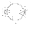
- FIG. 4 is an enlarged cross-sectional view of the shock absorber guide, the rotation preventing member, and the stroke sensor according to the embodiment of the present invention.
- FIG. 5 is a partially enlarged longitudinal sectional view showing the periphery of the restricting portion of the shock absorber according to the modification of the embodiment of the present invention.
- FIG. 1 is a side view schematically showing a vehicle including a shock absorber according to an embodiment of the present invention.
- FIG. 2 is a partial cross-sectional view of the shock absorber according to the embodiment of the present invention in
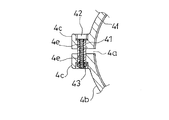
- FIG. 6A is a cross-sectional view showing a modification of the cut-off closing prevention structure in the guide of the shock absorber according to the embodiment of the present invention, and showing an enlarged part of the guide.
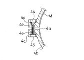
- FIG. 6B is a cross-sectional view illustrating another modified example of the cut-off closing prevention structure in the guide of the shock absorber according to the embodiment of the present invention, in which a part of the guide is enlarged.
- FIG. 7 is an enlarged cross-sectional view of a modification of the shock absorber adapter according to the embodiment of the present invention, together with a rotation preventing member and a stroke sensor.
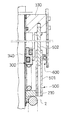
- FIG. 8 is a partially enlarged longitudinal sectional view of a related shock absorber.
- a shock absorber A As shown in FIG. 1, a shock absorber A according to an embodiment of the present invention is provided between a vehicle body B and a rear wheel W of a motorcycle V as a vehicle.
- the shock absorber A includes a shock absorber main body 1, a suspension spring 2 provided on the outer periphery of the shock absorber main body 1, and a lower end of the suspension spring 2 (lower end portion in FIG. 2). 2, a spring receiver 21 that supports the upper end of the suspension spring 2 (the upper end in FIG. 2), a jack 3 that adjusts the position of the spring receiver 21, and the spring receiver 21 and the jack 3.
- the stroke sensor 6 is provided.
- the shock absorber body 1 includes a cylindrical outer shell 10 and a rod 11 that is movably inserted into the outer shell 10, and exhibits a damping force that suppresses relative movement of the outer shell 10 and the rod 11 in the axial direction.
- Brackets 12 and 13 are fixed to the outer shell 10 and the rod 11, respectively.
- a bracket 12 fixed to the outer shell 10 is connected to the vehicle body B (see FIG. 1), and a bracket 13 fixed to the rod 11 is connected to a swing arm b1 (see FIG. 1) that supports the rear wheel W via a link (not shown). Connected.
- the rod 11 enters and exits the outer shell 10 and the shock absorber body 1 expands and contracts, and exhibits a damping force. And the suspension spring 2 expands and contracts together with the shock absorber main body 1, and the shock absorber A expands and contracts.
- the suspension spring 2 is a coil spring formed by winding a wire in a coil shape, and exhibits an elastic force against the compression when compressed.
- the spring receiver 20 is formed in an annular shape and provided on the outer periphery of the rod 11. The movement of the spring receiver 20 in the downward direction in FIG. 2 with respect to the rod 11 is restricted by the lower bracket 13 in FIG.
- the spring receiver 21 has an annular support portion 21a that abuts the upper end of the suspension spring 2 in FIG. 2, and a cylindrical extension portion 21b that extends upward from the support portion 21a in FIG. As for the cylindrical extension part 21b, the lower end in FIG. 2 is connected with the support part 21a.
- the spring receiver 21 is provided on the outer periphery of the outer shell 10 and is supported by the auxiliary spring 22 and the jack 3.
- the flange 14 is fixed to the outer periphery of the upper end portion of the outer shell 10 so as to protrude outward, and the outer periphery of the outer shell 10 lower than the flange 14 in FIG. It has been broken.
- the support portion 21 a of the spring receiver 21 is in sliding contact with the outer periphery of the guide 15 and is movable in the axial direction of the outer shell 10.
- An annular groove (not shown) along the circumferential direction is formed on the outer periphery of both end portions of the guide 15 in the axial direction, and snap rings 16 and 17 are fitted into the annular grooves.
- assistant spring 22, and the jack main body 30 mentioned later of the jack 3 are provided in the outer periphery of the guide 15 so that it may be located in a line substantially vertically from the lower side in FIG. Both snap rings 16 and 17 are used to prevent the removal.
- the jack 3 includes a jack body 30, a pump 31 that supplies hydraulic oil to the jack body 30, and a motor 32 that drives the pump 31.
- the pump 31 and the motor 32 may have any configuration, and a well-known configuration can be adopted. Here, detailed description of the pump 31 and the motor 32 is omitted. In the case where the pump 31 is a gear pump, the pump 31 is inexpensive and excellent in durability, and the hydraulic oil can be quickly supplied to the jack body 30.
- the jack body 30 includes an annular housing 33 that is provided on the outer periphery of the guide 15 and surrounds the guide 15, and an annular piston 34 that is slidably inserted between the housing 33 and the guide 15.
- a liquid chamber L is formed inside the housing 33 by the piston 34.
- the housing 33 has an annular base portion 33a and a cylindrical portion 33b extending downward from the base portion 33a in FIG.
- the housing 33 is arranged so that the base 33a on the bottom side faces upward in FIG.
- the piston 34 is formed in a bottomed cylindrical shape having an annular partition wall 34a and a cylindrical spacer 34b extending downward from the outer periphery of the partition wall 34a in FIG.
- the piston 34 is disposed such that the bottom partition wall 34a faces upward in FIG.
- an annular O-ring (not shown) is provided between the base portion 33a of the housing 33 and the guide 15, between the partition wall portion 34a and the guide 15 of the piston 34, and between the partition wall portion 34a and the cylindrical portion 33b. It is blocked by. Then, the liquid chamber L is defined by the base portion 33 a and the cylindrical portion 33 b of the housing 33, the partition wall portion 34 a of the piston 34, and the guide 15, and the hydraulic oil is filled in the liquid chamber L.
- the liquid chamber L is connected to the pump 31 via a hose or the like. When hydraulic oil is supplied to the liquid chamber L by the pump 31, the piston 34 moves downward in FIG. 2 and the liquid chamber L expands.
- the auxiliary spring 22 is a coil spring formed by winding a wire in a coil shape, and exhibits an elastic force against the compression when compressed.
- the lower end (lower end portion in FIG. 2) of the auxiliary spring 22 is supported by the support portion 21 a of the spring receiver 21, and the upper end (upper end portion in FIG. 2) is supported by the partition portion 34 a of the piston 34.
- the inner diameter of the auxiliary spring 22 is equal to or larger than the inner diameter of the partition wall 34a, and the outer diameter of the auxiliary spring 22 is equal to or smaller than the inner diameter of the spacer 34b. Therefore, the auxiliary spring 22 is inserted inside the spacer 34b. Further, when the piston 34 is retracted as shown on the left side in FIG. 2, the auxiliary spring 22 enters the cylindrical portion 33b while being supported by the partition wall portion 34a.
- the spring receiver 21 supports the upper end of the suspension spring 2 and is movable in the axial direction of the outer shell 10.
- An auxiliary spring 22 is connected in series with the suspension spring 2 via the spring receiver 21.
- a configuration including the suspension spring 2, the spring receiver 21, and the auxiliary spring 22 connected in series in this manner is referred to as a spring member S.
- the elastic force of the spring member S acts on the partition wall 34a of the piston 34, and the jack body 30 is pressed against the flange 14 by the elastic force.
- the housing 33 of the jack body 30 is prevented from coming off from the guide 15 by the upper snap ring 17 in FIG.
- the elastic force of the spring member S also acts on the lower spring receiver 20 in FIG. 2, and the spring receiver 20 is pressed against the bracket 13 by the elastic force.
- FIG. 2 shows the shock absorber A in a no-load state (a state where no load is applied).
- the length of the shock absorber A in the unloaded state corresponds to the natural length of the shock absorber A, and the shock absorber body 1 is fully extended.
- the right side of the center line shows a state where the piston 34 is advanced as much as possible, and the left side shows a state where the piston 34 is retracted as much as possible.
- the shock absorber A As shown on the right side in FIG. 2, in the shock absorber A, the spacer 34 b of the piston 34 comes into contact with the support portion 21 a of the spring receiver 21 when the piston 34 is advanced to the maximum in an unloaded state.
- the suspension spring 2 is bent by a certain amount by the piston 34 and the auxiliary spring 22, and initial deflection is given to the suspension spring 2. That is, a predetermined initial load is applied to the suspension spring 2.
- the shock absorber A may be laid back so that the piston 34 and the spring receiver 21 are separated from each other and the upper side of the spring receiver 21 in FIG. .
- the spring receiver 21 does not interfere with the lower snap ring 16 in FIG. 2 even when the piston 34 is advanced as much as possible. Therefore, the spring receiver 21 moves without being blocked by the snap ring 16. Further, when the shock absorber A is assembled, the snap ring 16 prevents the spring receiver 21 from coming out of the guide 15. Therefore, even if the spring receiver 21 receives the elastic force of the auxiliary spring 22, the shock absorber A can be easily assembled.
- the natural length of the auxiliary spring 22 is obtained by subtracting the initial deflection (compression length) of the suspension spring 2 from the stroke length of the piston 34 (the distance that the piston 34 moves from the maximum advanced state to the maximum retracted state). It is more than the length.
- auxiliary spring 22 a state where the piston 34 is advanced as much as possible and an initial load that gives the suspension spring 2 an initial deflection X (mm) is applied to the suspension spring 2 is defined as an optimum state of the shock absorber A.
- the stroke length of the piston 34 at Y is Y (mm).
- a case where the auxiliary spring 22 is not provided is considered as a comparative example. If the stroke length Y of the piston 34 is within a range that does not exceed the initial deflection X of the suspension spring 2, the suspension spring 2 will not be idle even if the piston 34 is retracted to the maximum in a no-load state. However, without the auxiliary spring 22, the stroke length Y of the piston 34 is increased and the vehicle height adjustment amount is increased without changing the conditions relating to the suspension spring 2, such as the suspension spring 2 and the initial load applied to the suspension spring 2. In such a case, the suspension spring 2 may be idle. Specifically, when the stroke length Y exceeds the initial deflection X, the suspension spring 2 may be idle.
- the shock absorber A includes the auxiliary spring 22, and the natural length of the auxiliary spring 22 is longer than the stroke length Y of the piston 34 minus the initial deflection X, that is, (YX). Therefore, even if the vehicle height adjustment amount is increased without changing the suspension spring 2, the auxiliary spring 22 fills the gap that allows the suspension spring 2 to move in the axial direction (excessive retraction), and the suspension spring 2 plays. It can prevent becoming a state.
- the contact height of the auxiliary spring 22 (the axial length in the most compressed state) is shorter than the axial length of the spacer 34b, and the spring constant of the auxiliary spring 22 is much higher than the spring constant of the suspension spring 2. small.
- the contact height of the auxiliary spring 22 means the axial length of the auxiliary spring 22 in a state where the shock absorber A is most compressed.
- Axial length means the length in the axial direction.
- axial position means a position in the axial direction.
- the auxiliary spring 22 will be described in detail.
- the auxiliary spring 22 In the state where the vehicle weight of the vehicle V (FIG. 1) stopped (still) on the horizontal ground is applied to the shock absorber A, that is, in the 1G state, the auxiliary spring 22 is attached to the spacer 34b.
- the auxiliary spring 22 contracts until it matches the axial length.
- the spring receiver 21 hits the tip of the spacer 34b, and the approach of the spring receiver 21 to the partition wall 34a is restricted. Therefore, the compression of the auxiliary spring 22 is prevented by the spacer 34 b, and the spring receiver 21 is supported by the auxiliary spring 22 and the spacer 34 b of the piston 34.
- the spring constant of the spring member S matches the spring constant of the suspension spring 2, and the vehicle body B is substantially supported only by the suspension spring 2.
- the spacer 34b may be eliminated, and in this case, the auxiliary spring 22 has a close contact height in the 1G state. That is, the spring receiver 21 may contact the spacer 34b in the riding 1G state, or the auxiliary spring 22 may have a close contact height.
- the suspension spring 2 is set so as not to have a contact height even when the shock absorber A is in the most contracted state.
- the adapter 4 includes a mounting portion 4b having a cut 4a in one circumferential direction and formed in a substantially C shape in plan view, and a periphery of the mounting portion 4b.
- a pair of fastening portions 4c, 4c that project outward from opposite ends of the direction, a pair of clamping portions 4d, 4d that project outward from the opposite side of the fastening portion 4c in the mounting portion 4b, and a mounting portion 4b A bolt 40 for closing the cut 4a, and a spacer 41 for preventing the cut 4a from closing.
- the pair of fastening portions 4c and 4c extend in the diameter direction of the attachment portion 4b and have opposing surfaces facing each other.
- the fastening portions 4c and 4c are formed with insertion holes 4e that are substantially orthogonal to the opposing surfaces and penetrate the fastening portions 4c and 4c.
- the spacer 41 is inserted from the insertion hole 4e of one fastening part 4c to the insertion hole 4e of the other fastening part 4c.
- Bolts 40 and 40 are screwed from both ends of the spacer 41. Even if the bolts 40 and 40 are screwed into the spacer 41 to the limit, a gap is formed between the tightening portions 4c and 4c, and the cut 4a is not closed.
- the spacer 41 prevents the inner diameter of the mounting portion 4b from becoming smaller than a predetermined value.
- the recessed part 4f is formed in the inner periphery of the attaching part 4b along the circumferential direction.
- the annular groove 21c along the circumferential direction is formed in the outer periphery of the extension part 21b in the spring receiver 21.
- a snap ring 23 is fitted in the annular groove 21c.
- the outer diameter of the snap ring 23 mounted in the annular groove 21c of the spring receiver 21 is larger than the outer diameter of the portion other than the annular groove 21c in the extension portion 21b, and the snap ring 23 is outward from the outer periphery of the extension portion 21b.
- the portion of the snap ring 23 that protrudes outward from the extension portion 21b when attached to the spring receiver 21 is referred to as a convex portion 21d.
- the convex portion 21 d fits into the concave portion 4 f of the adapter 4.
- the convex portion 21d and the concave portion 4f are both semicircular in longitudinal section.
- the diameter of the circle passing through the top of the convex portion 21d is the maximum outer diameter of the convex portion 21d
- the outer diameter of the portion other than the convex portion 21d in the extension portion 21b is the maximum outer diameter of the extension portion 21b.
- the diameter of a circle passing through the deepest part of the recess 4f when the bolts 40 and 40 are fastened to 41 see FIG.
- the maximum inner diameter of the recess 4f is the maximum inner diameter of the recess 4f, and the inner diameter of the mounting portion 4b other than the recess 4f is the mounting portion 4b.
- the maximum outer diameter of the convex portion 21d is equal to or smaller than the maximum inner diameter of the concave portion 4f, and the maximum outer diameter of the extension portion 21b is equal to or smaller than the minimum inner diameter of the mounting portion 4b.
- the adapter 4 can rotate in the circumferential direction (around the axis of the spring receiver 21) with respect to the spring receiver 21. Further, since the maximum outer diameter of the convex portion 21d is larger than the minimum inner diameter of the mounting portion 4b, the movement of the adapter 4 in the axial direction with respect to the spring receiver 21 is restricted by the convex portion 21d.
- the convex portion 21 d and the concave portion 4 f form a regulating portion 7 that regulates the movement of the adapter 4 in the axial direction with respect to the spring receiver 21. Further, since both the convex portion 21 d and the concave portion 4 f are annular, the restricting portion 7 allows the adapter 4 to rotate in the circumferential direction with respect to the spring receiver 21.
- the pair of sandwiching portions 4 d and 4 d of the adapter 4 extend in parallel with each other along the diameter direction of the mounting portion 4 b and are arranged at a predetermined interval in the circumferential direction of the mounting portion 4 b.
- the anti-rotation member 5 is sandwiched from both sides by the sandwiching portions 4d and 4d.
- channel 4g is formed in the outer peripheral part of the part located between the clamping parts 4d and 4d in the attaching part 4b.
- a spherical input element 60 of a stroke sensor 6 described later is inserted into the groove 4g.
- the anti-rotation member 5 is a rectangular plate-like member extending downward from the base 33a of the housing 33 in FIG.
- the upper end in FIG. 2 of the rotation preventing member 5 is fixed to the base 33a.
- the sandwiching portions 4d (FIG. 4) of the adapter 4 are in contact with both side ends of the anti-rotation member 5 (the end portion on the near side of the paper surface and the end portion on the back surface of the paper surface in FIG. 2).
- the rotation of the attachment portion 4b of the adapter 4 with respect to the anti-rotation member 5 is restricted by the sandwiching portion 4d.
- the width of the anti-rotation member 5 is constant vertically in FIG. Therefore, the adapter 4 can move up and down in FIG.
- the anti-rotation member 5 has an inner surface facing the shock absorber body 1 side.
- the stroke sensor 6 includes a sensor part 61 (FIGS. 3 and 4) attached to the inner surface of the rotation stopper member 5 and an input element 60 (FIGS. 3 and 4) pressed against the sensor part 61 by a spring 62 (FIG. 3). And have.
- the input element 60 is attached to the adapter 4.
- the stroke sensor 6 detects a change in the position of the input element 60 that contacts the sensor unit 61.
- the support portion 21a of the spring receiver 21 is provided with the piston 34.
- the spacer 34b, and the spacer 34b prevents the auxiliary spring 22 from being compressed. Therefore, during normal vehicle travel, the spring member S behaves so as to be composed only of the suspension spring 2.
- the shock absorber A is fully extended, such as when climbing over a level difference, the auxiliary spring 22 is prevented from extending and the suspension spring 2 playing even when the piston 34 is in the last retracted state.
- the support portion 21a of the spring receiver 21 is kept in contact with the spacer 34b.
- the vehicle weight or the like normally acts on the shock absorber A when adjusting the vehicle height for driving the piston 34 as described above. Therefore, the support portion 21 a of the spring receiver 21 contacts the spacer 34 b of the piston 34 and moves while being supported by the piston 34.
- the adapter 4 is attached to the spring receiver 21 in a state in which the axial movement with respect to the spring receiver 21 is restricted, and the pair of holding portions 4 d and 4 d of the adapter 4 sandwich the rotation prevention member 5. Therefore, when the piston 34 is moved, the spring receiver 21 moves upward and downward in FIG. 2 in a state where it abuts against the spacer 34 b of the piston 34, and the adapter 4 extends along the anti-rotation member 5 in FIG. Slide to.
- the position of the input element 60 changes, and the stroke sensor 6 detects the axial displacement of the spring receiver 21 relative to the outer shell 10 based on the position of the input element 60 relative to the sensor unit 61.
- the position of the spring receiver 21 is detected by the stroke sensor 6, even when the vehicle is traveling, the amount of expansion / contraction of the suspension spring 2 varies, and the position of the spring receiver 21 cannot be obtained from the amount of expansion / contraction of the shock absorber body 1.
- the position of the spring receiver 21 can be grasped, and the vehicle height can be adjusted while the vehicle is running.
- the adapter 4 is rotatable with respect to the spring receiver 21. For this reason, when a rotational force acts on the spring receiver 21 due to the compression of the suspension spring 2, even if the adapter 4 is prevented from rotating with respect to the shock absorber body 1 by the anti-rotation member 5, the spring receiver receives the rotational force. 21 can rotate. Therefore, the rotational force is not applied to the holding portion 4d of the adapter 4 that slides with the rotation stopper member 5, and the adapter 4 can slide without resistance. For this reason, even if the spring receiver 21 moves up and down in a state of receiving the rotational force due to the compression of the suspension spring 2, the spring receiver 21 does not tilt and a force is evenly applied to the piston 34. Therefore, it is possible to prevent the piston 34 from being inclined and the piston 34 and the housing 33 from being heavily worn.
- FIG. 8 is a longitudinal sectional view of a shock absorber that can determine the axial position of the spring support regardless of the type of pump.
- the rotation of the spring receiver 210 is restricted by the rotation preventing member 500, and the displacement of the spring receiver 210 is detected by the stroke sensor 600.
- the detent member 500 includes a cylindrical arm 501 attached to a side portion of the annular spring receiver 210 and a rod 502 attached to the housing 330 of the jack 300 and slidably inserted into the arm 501.
- a rotational force is input to the spring receiver 210 due to the contraction of the suspension spring 2, but the rotation of the spring receiver 210 and the arm 501 is restricted by the rod 502.
- the spring receiver 210 moves up and down in FIG. 8 due to the expansion and contraction of the suspension spring 2
- the rod 502 moves in and out of the arm 501 and the rotation preventing member 500 expands and contracts. That is, the rotation stopper member 500 restricts the rotation of the spring receiver 210 while allowing the spring receiver 210 to move in the axial direction. Therefore, even if the stroke sensor 600 is configured to detect one axial displacement in the circumferential direction of the spring receiver 210, the stroke sensor 600 is not twisted. Therefore, the axial position of the spring receiver 210 can be accurately obtained.
- a rotational force due to contraction of the suspension spring 2 acts on the sliding portion of the rod 502 and the arm 501 in the rotation preventing member 500. Therefore, the frictional force between the arm 501 and the rod 502 is increased, and the rotation preventing member 500 may not easily expand and contract.
- the spring receiver 210 When it becomes difficult for the rotation preventing member 500 to expand and contract, in the spring receiver 210, the moving speed on the side connected to the rotation preventing member 500 becomes slower than the moving speed on the side not connected to the rotation preventing member 500.
- the receptacle 210 may be inclined with respect to the axial direction.
- the shock absorber A even if the piston 34 rotates, the axial position of the spring receiver 21 can be easily detected from the axial position of the piston 34.
- the shock absorber A in which the suspension spring 2 applies a rotational force to the piston 34 via the spring receiver 21 when the suspension spring 2 is compressed it is not necessary to restrict the rotation of the spring receiver 21. Axial movement is not hindered. Therefore, it is possible to suppress the spring receiver 21 from being inclined and applying an uneven load to the piston 34. Therefore, wear of the piston 34 and the housing 33 of the jack body 30 can be suppressed.
- the spring receiver 21 has a support portion 21a that supports the upper end (one end) of the suspension spring 2, and an extension portion 21b that extends from the support portion 21a to the upper side (anti-suspension spring side).
- the adapter 4 is attached to the extension portion 21b.
- the extension portion 21b extends from the support portion 21a to the side opposite to the suspension spring 2, and is provided on the auxiliary spring 22 and the piston 34 so as to overlap the outer side (the side opposite to the shock absorber body 1). Therefore, the attachment position of the adapter 4 can be brought close to the base portion 33a of the housing 33 to which the detent member 5 is coupled.
- the configuration of the spring receiver 21 is not limited to the above.
- the extension part 21b may be abolished and the adapter 4 may be attached to the support part 21a.
- it is necessary to shift the detent member 5 downward in FIG. Since the base 33a of the housing 33 must be provided with a connection port for connecting a hose for supplying liquid to the liquid chamber L, it is difficult to move the base 33a downward.
- the shape of the housing 33 becomes complicated.
- the anti-rotation member 5 is connected to the housing 33 without changing the shape of the housing 33, the anti-rotation member 5 must be extended.
- the extension part 21b is provided in the spring receiver 21, and the adapter 4 is attached to the extension part 21b, the shape of the housing 33 can be simplified and the rotation preventing member 5 can be shortened.
- the spring receiver 21 is formed by screwing one end of a cylindrical extension portion 21b to the support portion 21a.
- the support part 21a and the extension part 21b may be integrated in advance as one member.
- the extension portion 21 b is formed in a cylindrical shape, and the inner diameter of the extension portion 21 b is larger than the outer diameter of the cylinder portion 33 b of the housing 33. Therefore, a gap is formed between the extension portion 21b and the cylindrical portion 33b, and the extension portion 21b and the housing 33 do not interfere with each other.
- the extension portion 21 b may be in sliding contact with the outer periphery of the housing 33.
- the configuration of the extension 21b can be changed as appropriate as long as the adapter 4 is supported.
- the extension portion 21b may be configured to include a plurality of rods or one or more plates arranged in the circumferential direction of the support portion 21a.
- the stroke sensor 6 includes an input element 60 provided in the adapter 4 and a sensor unit 61 that is attached to the rotation preventing member 5 and detects the position of the input element 60.
- the adapter 4 is provided close to the anti-rotation member 5 so as to be anti-rotated by the anti-rotation member 5. Therefore, when the input element 60 is provided on the adapter 4 and the sensor unit 61 is provided on the rotation preventing member 5 as described above, the rotational direction of the input element 60 and the sensor unit 61 can be prevented from being shifted, and the input element 60 is connected to the sensor unit. Easy to contact 61.
- the configuration of the sensor when the stroke sensor 6 is a contact type, the configuration of the sensor can be simplified and the sensor is not bulky. Therefore, the buffer A can be prevented from being enlarged and the mountability of the buffer A can be improved.
- the configuration of the stroke sensor 6 is not limited to the above, and can be changed as appropriate.
- a non-contact type sensor may be used as the stroke sensor 6, or a wire type sensor that detects the amount of displacement from the length of the wire drawn with the movement of the adapter 4 with respect to the detent member 5 may be used. .
- a wire type sensor that detects the amount of displacement from the length of the wire drawn with the movement of the adapter 4 with respect to the detent member 5 may be used. .
- Such a change is possible regardless of the configuration of the spring receiver 21.
- the restricting portion 7 has a convex portion 21 d provided on the spring receiver 21 and a concave portion 4 f provided on the adapter 4. Since the restricting portion 7 is formed by the unevenness, the structure of the restricting portion 7 can be extremely simplified and the cost can be reduced. Furthermore, since the outer diameter of the adapter 4 can be reduced, the shock absorber A can be reduced in size.
- the configuration of the restricting portion 7 is not limited to the above, and can be appropriately changed as long as the adapter 4 can be prevented from moving in the axial direction with respect to the spring receiver 21 without hindering the rotation of the adapter 4 with respect to the spring receiver 21.
- the convex portion 21d is formed by the outer peripheral portion of the snap ring 23 attached to the outer periphery of the spring receiver 21.
- the convex part 21d may be formed by projecting a part of the spring receiver 21 outward.
- the restricting portion 7 may be formed by a convex portion 4 h provided on the inner periphery of the adapter 4 and a concave portion 21 e provided on the outer periphery of the spring receiver 21 and into which the convex portion 4 h is fitted. Good.
- the convex portions 21d and 4h may be a plurality of protrusions arranged in the circumferential direction as long as the concave portions 4f and 21e are formed in an annular shape. If the convex portions 21d and 4h are formed in an annular shape, even if the concave portions 4f and 21e are interrupted by the cut 4a or the like as shown in FIG.
- the convex portions 21d and 4h are a plurality of protrusions arranged in the circumferential direction and the concave portions 4f and 21e are interrupted in the circumferential direction, when the adapter 4 rotates with respect to the spring receiver 21, some of the convex portions 21d and 4h (Protrusions) may come off from the recesses 4f and 21e. Some convex portions 21d and 4h (protrusions) once removed from the concave portions 4f and 21e may not be inserted into the concave portions 4f and 21e again.
- the convex portions 21d and 4h are formed in an annular shape, the convex portions 21d and 4h (protrusions) can be prevented from coming off from the concave portions 4f and 21e. Such a change is possible regardless of the configuration of the spring receiver 21 and the stroke sensor 6.
- the adapter 4 is provided with a cut 4a at one place in the circumferential direction. For this reason, if the cut 4a is widened, the adapter 4 can be easily mounted on the outer periphery of the spring receiver 21, and the adapter 4 can be easily prevented from coming off from the outer periphery of the spring receiver 21 by closing the cut 4a.
- the number of cuts 4a can be changed as appropriate.
- the cut 4a may be provided at two places on the attachment portion 4b, and the attachment portion 4b may be divided into two arc-shaped members.
- the attachment portion 4b may be divided into three or more. If the adapter 4 can be divided into a plurality of members, the adapter 4 can be formed of a material that is difficult to elastically deform.
- the attachment portion 4b has elasticity, or after the adapter 4 is attached to the outer periphery of the spring receiver 21, the movement of the adapter 4 in the axial direction relative to the spring receiver 21 can be restricted.
- the cut line 4a may be eliminated, and the attachment portion 4b may be annular. Such a change is possible regardless of the configuration of the spring receiver 21, the stroke sensor 6, and the restricting portion 7.
- the adapter 4 is provided with a cut 4 a and set so that the cut 4 a is not closed.
- the adapter 4 is mounted on the outer periphery of the spring receiver 21 while allowing the adapter 4 to move with respect to the spring receiver 21. (Is loosely fitted).
- the method of loose fitting can be changed as appropriate.
- the configuration for preventing the cut 4a from closing and closing may be changed as shown in FIGS. 6A and 6B.
- the bolt 42 is screwed to the inner periphery of the spacer 41, the tip of the screw shaft of the bolt 42 is protruded from the spacer 41, and the nut 43 is screwed to the protruding portion.
- FIG. 6A the bolt 42 is screwed to the inner periphery of the spacer 41, the tip of the screw shaft of the bolt 42 is protruded from the spacer 41, and the nut 43 is screwed to the protruding portion.
- a long nut 44 with a head is inserted from the insertion hole 4e of one tightening portion 4c through the insertion hole 4e of the other tightening portion 4c, and a bolt 45 is screwed from the tip of the long nut 44.
- the inner diameter of the mounting portion 4b is made larger than the outer diameter of the spring receiver 21 so that the adapter 4 and the spring receiver 21 rotate relative to each other. The resistance at the time can be reduced.
- the state in which the adapter 4 is loosely fitted to the spring receiver 21 is not limited to a state in which a clearance is provided between the adapter 4 and the spring receiver 21, as long as the spring receiver 21 moves relative to the adapter 4.
- the spring receiver 21 may slide the adapter 4.
- a groove 4 i extending in the circumferential direction is provided on the outer periphery of the mounting portion 4 b, and the tightening force of the snap ring 46 fitted in the groove 4 i is set so as to allow the adapter 4 to move with respect to the spring receiver 21. May be. Such a change is possible regardless of the configuration of the spring receiver 21, the stroke sensor 6, and the restricting portion 7.
- the shock absorber A includes a shock absorber body 1, a suspension spring 2 that urges the shock absorber body 1 in the extending direction, and a spring receiver that supports the upper end (one end) of the suspension spring 2 in FIG. 21, a jack 3 that changes the axial position of the spring receiver 21, an annular adapter 4 that is loosely fitted on the outer periphery of the spring receiver 21, and the spring receiver 21 and the adapter 4.
- the restricting portion 7 that restricts the axial movement of the adapter 4 with respect to the anti-rotation member, the anti-rotation member 5 that is attached to the shock absorber body 1 and prevents the adapter 4 from rotating.
- a stroke sensor 6 is provided between the adapter 4 and the anti-rotation member 5.
- the stroke sensor 6 is provided in this way, the position of the spring receiver 21 in the axial direction can be easily obtained regardless of the type of the pump 31 constituting the jack 3. Therefore, it is possible to employ a pump that is optimal for the vehicle height adjustment amount and the vehicle height adjustment timing.
- a pump with internal leakage such as a gear pump or a vane pump
- the pump 31 that supplies hydraulic oil to the liquid chamber L
- the amount of liquid sent from the pump 31 to the liquid chamber L cannot be accurately grasped. For this reason, it is difficult to obtain the position of the spring receiver 21 based on the amount of liquid, and this embodiment is effective for a shock absorber using such a pump 31.
- the gear pump when receiving a signal such as traffic permission by a traffic signal or a stop instruction, the gear pump is suitable for adjusting the vehicle height and obtaining a good footing property when the vehicle is driven and stopped. Because the gear pump is excellent in durability and can increase the discharge amount per unit time, it can be used for a long period of time even if the vehicle height adjustment frequency is large. This is because adjustment is possible.
- the adapter 4 is loosely fitted to the outer periphery of the spring receiver 21 so that the adapter 4 can be fitted to the outer periphery of the spring receiver 21 so that the adapter 4 can move relative to the spring receiver 21.
- the adapter 4 is loosely fitted to the spring receiver 21 and the movement of the adapter 4 in the axial direction with respect to the spring receiver 21 is restricted by the restricting portion 7, the adapter 4 is fixed in the axial direction of the spring receiver 21. It becomes possible to rotate in the circumferential direction along the outer periphery of the spring receiver 21 at the position.
- the rotation of the adapter 4 is restricted by the anti-rotation member 5, while the adapter 4 is rotatable with respect to the spring receiver 21. Therefore, when the suspension spring 2 is compressed and a rotational force acts on the spring receiver 21, the spring receiver 21 can rotate relative to the adapter 4 by receiving the rotational force. Therefore, even if the relative rotation between the adapter 4 and the rotation preventing member 5 is restricted due to the provision of the stroke sensor 6, the rotational force does not substantially act on the clamping portion 4d that restricts the rotation between the adapter 4 and the rotation preventing member 5. Therefore, the frictional force between the clamping portion 4d and the rotation prevention member 5 does not increase, and the adapter 4 can slide along the rotation prevention member 5 without resistance.
- the adapter 4 is provided with a pair of holding portions 4d and 4d, and the anti-rotation member 5 is inserted between the holding portions 4d to prevent the adapter 4 from rotating.
- the structure for restricting the rotation of the adapter 4 can be changed as appropriate.
- the adapter 4 may be provided with a ring, and the anti-rotation member 5 may be inserted into the ring with a cylindrical rod.
- the anti-rotation member 5 is attached to the shock absorber main body 1 via the housing 33, but the anti-rotation member 5 may be directly attached to the shock absorber main body 1, or the housing 33. It may be attached via other members. That is, the anti-rotation member 5 does not have to move with respect to the shock absorber body 1.
- the shock absorber A includes an auxiliary spring 22 interposed between the piston 34 and the spring receiver 21 and a spacer 34 b provided in parallel with the auxiliary spring 22.
- the spacer 34 b is provided on the piston 34.
- the axial length of the spacer 34 b is longer than the contact height of the auxiliary spring 22.
- the suspension spring 2 can be prevented from being idle even if the vehicle height adjustment amount is increased without changing the suspension spring 2.
- the axial length of the spacer 34 b of the piston 34 is longer than the contact height of the auxiliary spring 22. Therefore, no load is applied to the auxiliary spring 22 in a state in which the auxiliary spring 22 is in close contact height, that is, in a state where the coil portions (one turn of the auxiliary spring 22) are in contact with each other. Therefore, it is possible to prevent the stress exceeding the allowable stress from acting on the wire forming the auxiliary spring 22.
- the auxiliary spring 22 is provided inside the spacer 34 b, the auxiliary spring 22 is disposed between the partition wall 34 a of the piston 34 and the spring receiver 21.
- the axial length of the partition wall 34a of the piston 34 is increased, the axial length of the shock absorber A is increased. For this reason, it is difficult to suppress the inclination of the piston 34 by increasing the fitting length of the piston 34 to the outer shell 10.
- the shock absorber A including the auxiliary spring 22 it is preferable to suppress the inclination of the piston 34 by using the adapter 4, the restriction portion 7, the rotation stopper member 5, and the stroke sensor 6 as described above.
- the configuration of the piston 34 is not limited to the above, and can be changed as appropriate.
- the partition wall 34a and the spacer 34b of the piston 34 are integrally formed as one part. However, even if these are separately formed, they may be integrated by welding, bonding, screwing, or the like. Good.
- the spacer 34b may be eliminated from the piston 34, and the spacer 34b may be provided in the spring receiver 21, or the auxiliary spring 22 and the spacer 34b may be eliminated.
- the guide 15 is provided on the outer periphery of the outer shell 10 and the spring receiver 21 and the piston 34 are in sliding contact with the guide 15, but the guide 15 may be eliminated.
- the spring receiver 21 and the piston 34 may be in direct sliding contact with the outer periphery of the outer shell 10.
- the outer periphery of the outer shell 10 is preferably formed smoothly.
- the shock absorber A is set to a so-called inverted type in which the outer shell 10 is connected to the vehicle body B and the rod 11 is connected to the rear wheel W, but the shock absorber A is set to be an upright type. May be. In the upright shock absorber A, the outer shell 10 is connected to the rear wheel W, and the rod 11 is connected to the vehicle body B.
- shock absorber A is provided between the vehicle body B and the rear wheel W of the motorcycle, the shock absorber A may be used for a straddle-type vehicle other than the motorcycle, an automobile, or the like.
Landscapes
- Engineering & Computer Science (AREA)
- Mechanical Engineering (AREA)
- General Engineering & Computer Science (AREA)
- Fluid-Damping Devices (AREA)
- Vehicle Body Suspensions (AREA)
Abstract
緩衝器Aは、緩衝器本体1を伸長方向へ附勢する懸架ばね2の一端を支持するばね受21と、ばね受21の軸方向位置を変更するジャッキ3と、ばね受21の外周に遊嵌される環状のアダプタ4と、ばね受21とアダプタ4との間に設けられて、ばね受21に対するアダプタ4の軸方向の移動を規制する規制部7と、緩衝器本体1に取り付けられてアダプタ4の回り止めをする回り止め部材5と、アダプタ4と回り止め部材5との間に設けたストロークセンサ6とを備える。
Description
本発明は、緩衝器に関する。
従来、緩衝器は、二輪車又は三輪車等の鞍乗型車両の後輪を支持するのに利用されている。JP2010-149548Aに開示される緩衝器は、コイルばねといった懸架ばねの一端を支持するばね受をジャッキで駆動し、車高を調整できるように構成される。
具体的には、JP2010-149548Aのジャッキは、ハウジングと、このハウジング内に移動可能に挿入されてハウジング内に液室を形成するピストンと、液室に液体を供給するポンプとを備える。そして、当該ポンプは単一のポンプ室を有するレシプロ式のポンプであり、ポンプのピストン断面積にその移動距離を乗じることによって得られる容積分の液体が液室に供給される。このため、液室へ供給された液量が略正確にわかるので、当該液量からばね受の位置が略正確に求められる。
車両を支持する緩衝器において、停車時の足つき性の向上を目的として車高調整量を増やす場合がある。この場合、レシプロ式のポンプが不向きであり、ギヤポンプといった他の種類のポンプが適する。しかしながら、ギヤポンプといったポンプでは内部漏れが生じる。そのため、このようなポンプを利用すると、ポンプから液室へ供給される液量を正確に把握できず、上記液量からばね受の位置を正確に求められない。
ポンプから液室へ供給される液量を用いることなくばね受の位置を求めるために、ばね受の側部にストロークセンサを取り付けてばね受の周方向の一ヶ所の変位を検出することも考えられる。しかし、従来の緩衝器では、懸架ばねは圧縮されるとばね受を回転させるので、ストロークセンサが捩じられるとともに、当該センサではばね受の軸方向位置を正確に求められない。
本発明は、ばね受の軸方向位置を正確に求めることができる緩衝器の提供を目的とする。
本発明のある態様によれば、緩衝器は、緩衝器本体と、緩衝器本体を伸長方向へ附勢する懸架ばねと、懸架ばねの一端を支持するばね受と、ばね受の軸方向位置を変更するジャッキと、ばね受の外周に遊嵌される環状のアダプタと、ばね受とアダプタの間に設けられて、ばね受に対するアダプタの軸方向の移動を規制する規制部と、緩衝器本体に取り付けられてアダプタの回り止めをする回り止め部材と、アダプタと回り止め部材との間に設けたストロークセンサとを備える。
以下に本発明の実施形態について、図面を参照しながら説明する。いくつかの図面を通して付された同じ符号は、同じ部品か対応する部品を示す。
図1に示すように、本発明の実施形態に係る緩衝器Aは、車両としての自動二輪車Vの車体Bと後輪Wとの間に設けられる。そして、緩衝器Aは、図2に示すように、緩衝器本体1と、緩衝器本体1の外周に設けられた懸架ばね2と、懸架ばね2の下端(図2における下側の端部)を支持するばね受20と、懸架ばね2の上端(図2における上側の端部)を支持するばね受21と、ばね受21の位置を調整するジャッキ3と、ばね受21とジャッキ3との間に設けられる補助ばね22と、ばね受21の外周に遊嵌される環状のアダプタ4と、アダプタ4の回り止めをする回り止め部材5と、アダプタ4と回り止め部材5との間に設けられたストロークセンサ6とを備える。
緩衝器本体1は、筒状のアウターシェル10と、アウターシェル10内に移動可能に挿入されるロッド11とを備え、アウターシェル10とロッド11の軸方向の相対移動を抑制する減衰力を発揮する。アウターシェル10とロッド11には、それぞれブラケット12,13が固定される。アウターシェル10に固定されるブラケット12が車体B(図1参照)に連結され、ロッド11に固定されるブラケット13が、後輪Wを支えるスイングアームb1(図1参照)に図示しないリンクを介して連結される。路面凹凸による衝撃が後輪Wに入力されると、ロッド11がアウターシェル10に出入りして緩衝器本体1が伸縮し、減衰力を発揮する。そして、緩衝器本体1とともに懸架ばね2が伸縮し、緩衝器Aが伸縮する。
懸架ばね2は、線材をコイル状に巻き回して形成されたコイルばねであり、圧縮されると当該圧縮に抗する弾性力を発揮する。ばね受20は、環状に形成されてロッド11の外周に設けられる。ロッド11に対する図2中下方へのばね受20の移動は、図2中下側のブラケット13により規制される。また、ばね受21は、懸架ばね2の図2中上端に当接する環状の支持部21aと、支持部21aから図2中上方へ延びる筒状の延長部21bとを有する。筒状の延長部21bは、図2中下端が支持部21aに連結される。ばね受21は、アウターシェル10の外周に設けられ、補助ばね22及びジャッキ3で支えられる。
より詳細には、アウターシェル10の上端部外周には、フランジ14が外側に突出するように固定され、アウターシェル10におけるフランジ14よりも図2中下側の外周が筒状のガイド15により覆われている。ばね受21の支持部21aは、ガイド15の外周に摺接し、アウターシェル10の軸方向に移動自在である。ガイド15における軸方向の両端部の外周には、周方向に沿う環状溝(符示せず)が形成され、各環状溝にスナップリング16,17が嵌る。そして、ガイド15の外周に、ばね受21の支持部21a、補助ばね22、及びジャッキ3の後述するジャッキ本体30が図2中下側から順に略縦に並ぶように設けられ、これらが全体として両スナップリング16,17で抜け止めされている。
ジャッキ3は、ジャッキ本体30と、ジャッキ本体30に作動油を供給するポンプ31と、ポンプ31を駆動するモータ32とを備える。ポンプ31及びモータ32は、如何なる構成であってもよく、周知の構成を採用できる。ここではポンプ31及びモータ32の詳細な説明を省略する。なお、ポンプ31がギヤポンプである場合には、ポンプ31が安価であるとともに、耐久性に優れ、ジャッキ本体30へ作動油を素早く供給できる。
ジャッキ本体30は、ガイド15の外周に設けられてガイド15を囲む環状のハウジング33と、ハウジング33とガイド15との間に摺動自在に挿入される環状のピストン34とを備える。ピストン34によって、ハウジング33の内側に液室Lを形成される。ハウジング33は、環状の基部33aと、基部33aから図2中下方へ延びる筒部33bとを有して有底筒状に形成される。そして、ハウジング33は、底側の基部33aが図2中上方を向くように配置される。また、ピストン34は、環状の隔壁部34aと、隔壁部34aの外周部から図2中下方へ延びる筒状のスペーサ34bとを有して有底筒状に形成される。そして、ピストン34は、底側の隔壁部34aが図2中上方を向くように配置されている。
さらに、ハウジング33の基部33aとガイド15との間、ピストン34の隔壁部34aとガイド15との間、及び隔壁部34aと筒部33bとの間は、それぞれ環状のOリング(符示せず)で塞がれている。そして、ハウジング33の基部33a及び筒部33b、ピストン34の隔壁部34a、並びにガイド15によって液室Lが画定され、作動油が液室Lに充填される。液室Lはホース等を介してポンプ31に接続される。ポンプ31により液室Lに作動油が供給されると、ピストン34が図2中下方へ移動して液室Lが拡大する。反対に、ポンプ31により液室Lから作動油が排出されると、ピストン34が図2中上方へ移動して液室Lが縮小する。以下において、液室Lが拡大する方向へのピストン34の移動を「前進」とも称し、液室Lが縮小する方向へのピストン34の移動を「後退」とも称する。
補助ばね22は、線材をコイル状に巻き回して形成されたコイルばねであり、圧縮されると当該圧縮に抗する弾性力を発揮する。補助ばね22の下端(図2における下側の端部)はばね受21の支持部21aにより支えられ、上端(図2における上側の端部)はピストン34の隔壁部34aにより支えられる。補助ばね22の内径は隔壁部34aの内径以上であり、補助ばね22の外径はスペーサ34bの内径以下である。そのため、補助ばね22はスペーサ34bの内側に挿入される。また、図2中左側に示すようにピストン34を後退させると、補助ばね22は隔壁部34aにより支えられたまま筒部33b内に進入する。
ばね受21は、前述のように、懸架ばね2の上端を支えるとともに、アウターシェル10の軸方向に移動自在である。当該ばね受21を介して補助ばね22が懸架ばね2と直列に接続される。以下において、このように直列に接続された懸架ばね2、ばね受21及び補助ばね22からなる構成をばね部材Sと称する。ばね部材Sの弾性力はピストン34の隔壁部34aに作用し、ジャッキ本体30は、上記弾性力によりフランジ14に押し付けられる。
また、ジャッキ本体30のハウジング33は、図2中上側のスナップリング17でガイド15に対して抜け止めされている。ジャッキ本体30がばね部材Sの弾性力によりフランジ14に押し付けられると、アウターシェル10に対する軸方向へのガイド15移動がスナップリング17とフランジ14により規制される。ばね部材Sの弾性力は図2中下側のばね受20にも作用し、ばね受20が上記弾性力によりブラケット13に押し付けられる。その結果、緩衝器本体1が伸縮するとばね部材Sが伸縮し、当該ばね部材Sにより車体B(図1)が弾性支持される。
図2は、無負荷状態(負荷がかかっていない状態)の緩衝器Aを示している。無負荷状態における緩衝器Aの長さが緩衝器Aの自然長に相当し、緩衝器本体1が伸び切る。そして、図2中中心線の右側にピストン34を最大限前進させた状態を示し、左側にピストン34を最大限後退させた状態を示している。
図2中右側に示すように、緩衝器Aでは、無負荷状態においてピストン34が最大限前進している場合には、ピストン34のスペーサ34bがばね受21の支持部21aに接触する。ピストン34と補助ばね22により懸架ばね2が一定量撓み、初期撓みが懸架ばね2に与えられる。つまり、懸架ばね2に所定のイニシャル荷重がかけられる。緩衝器Aは、懸架ばね2に初期撓みを与えた状態で、ピストン34とばね受21が離間し補助ばね22のみでばね受21の図2中上側が支えられるように背呈されてもよい。
また、ばね受21は、ピストン34を最大限前進させた状態でも、図2中下側のスナップリング16に干渉しない。したがって、ばね受21は、スナップリング16に妨げられることなく移動する。また、緩衝器Aの組立時には、スナップリング16は、ばね受21がガイド15から抜け出るのを防止する。そのため、ばね受21が補助ばね22の弾性力を受けても、緩衝器Aを容易に組立てることができる。
図2中左側に示すように、無負荷状態においてピストン34が最大限後退している場合には、ピストン34がハウジング33の基部33aに当接し、懸架ばね2と補助ばね22の長さが自然長(自由高さ)に近くなる。ピストン34の隔壁部34aの図2中上端部における外周側には環状の凹み34cが設けられている。当該凹み34cは、液室Lとホースとをつなぐ流路の開口に対向する。そのため、ピストン34が基部33aに突き当てられた状態においても、作動油の圧力をピストン34の凹み34cに作用させることができる。つまり、最後退時におけるピストン34の受圧面積を大きくすることができる。なお、上記凹み34cを基部33a側に設けてもよい。
補助ばね22の自然長は、ピストン34のストローク長(ピストン34が最大限前進した状態から最大限後退した状態になるまでに移動する距離)から、懸架ばね2の初期撓み(圧縮長)を引いた長さ以上である。
ここで、補助ばね22の作用について説明する。補助ばね22の説明に際して、例えば、ピストン34を最大限前進させ、かつ懸架ばね2に初期撓みX(mm)を与えるイニシャル荷重を懸架ばね2にかけた状態を緩衝器Aの最適状態とし、この状態でのピストン34のストローク長をY(mm)とする。
まず、比較例として、補助ばね22がない場合を考える。ピストン34のストローク長Yが懸架ばね2の初期撓みXを超えない範囲であれば、無負荷状態でピストン34を最大限後退させても懸架ばね2は遊んだ状態にならない。しかし、補助ばね22がない状態で、懸架ばね2、及び懸架ばね2にかけるイニシャル荷重等、懸架ばね2に係る条件を変更せずにピストン34のストローク長Yを増やして車高調整量を増やした場合、懸架ばね2が遊んだ状態になることがある。具体的には、ストローク長Yが初期撓みXを超えると、懸架ばね2が遊んだ状態になることがある。なぜなら、無負荷状態でピストン34が前進限から後退し懸架ばね2がX(mm)伸びて自然長になっても、ピストン34はさらにY-X(mm)後退できるためである。この余剰後退(Y-X)分、懸架ばね2は軸方向に移動可能であり、遊ぶことになる。
これに対して、緩衝器Aは、補助ばね22を備え、補助ばね22の自然長は、ピストン34のストローク長Yから初期撓みXを引いた長さ、即ち(Y-X)よりも長い。そのため、懸架ばね2を変えずに車高調整量を増やしたとしても、補助ばね22は、懸架ばね2が軸方向に動ける分(余剰後退分)の隙間を埋めて、懸架ばね2が遊んだ状態になるのを防止できる。
さらに、補助ばね22の密着高さ(最圧縮状態での軸方向長さ)は、スペーサ34bの軸方向長さよりも短く、補助ばね22のばね定数は、懸架ばね2のばね定数よりも格段に小さい。ここで、「補助ばね22の密着高さ」とは、緩衝器Aが最圧縮した状態での補助ばね22の軸方向長さを意味する。「軸方向長さ」とは、軸方向における長さを意味する。また、以下における「軸方向位置」とは、軸方向における位置を意味する。
補助ばね22について具体的に説明すると、水平な地面上で停車(静止)した車両V(図1)の車重が緩衝器Aにかかる状態、即ち、1G状態では、補助ばね22がスペーサ34bの軸方向長さと一致するまで補助ばね22が縮む。ばね受21はスペーサ34bの先端に突き当たり、隔壁部34aへのばね受21の接近が規制される。よって、補助ばね22の圧縮がスペーサ34bにより妨げられ、ばね受21が補助ばね22とピストン34のスペーサ34bとによって支えられる。
つまり、1G状態では、ばね受21とピストン34の隔壁部34aとの接近がスペーサ34bにより規制され、補助ばね22の圧縮が妨げられる。そのため、ばね部材Sのばね定数は、懸架ばね2のばね定数に一致し、車体Bは実質的に懸架ばね2のみで支えられる。なお、スペーサ34bを廃してもよく、この場合には、1G状態で補助ばね22は密着高さになる。つまり、乗車1G状態でばね受21がスペーサ34bに当接するようにしたり、補助ばね22が密着高さになるようにしたりしてもよい。一方で、懸架ばね2は、緩衝器Aが最収縮した状態であっても密着高さにはならないように設定されている。
図3に示すように、ばね受21に対する軸方向への環状のアダプタ4の移動は、規制部7により規制される。また環状のアダプタ4は、回り止め部材5により緩衝器本体1に対して回り止めされている。より詳細に説明すると、図4に示すように、アダプタ4は、周方向の一カ所に切れ目4aを有して平面視で略C字状に形成される取付部4bと、取付部4bの周方向の両端から相対向して外方へ突出する一対の締め部4c,4cと、取付部4bにおける締め部4cの反対側から外方へ突出する一対の挟持部4d,4dと、取付部4bの切れ目4aを閉めるボルト40と、切れ目4aが閉め切るのを防止するスペーサ41とを有する。
一対の締め部4c,4cは、取付部4bの直径方向に延び、互いに対向する対向面を有する。また、締め部4c,4cには、対向面に略直交し締め部4c,4cを貫通する挿通孔4eが形成されている。スペーサ41は、一方の締め部4cの挿通孔4eから他方の締め部4cの挿通孔4eにかけて挿入される。スペーサ41の両端からボルト40,40が螺合される。そして、ボルト40,40をスペーサ41内に限界までねじ込んだとしても、締め部4c,4cの間に隙間ができて切れ目4aが閉じられない。このように、スペーサ41によって、取付部4bの内径が所定よりも小さくなるのが防止されている。
取付部4bの内周には、周方向に沿って凹部4fが形成されている。また、図3に示すように、ばね受21における延長部21bの外周には、周方向に沿う環状溝21cが形成されている。環状溝21cにはスナップリング23が嵌る。ばね受21の環状溝21cに装着された状態のスナップリング23の外径は、延長部21bにおける環状溝21c以外の部分の外径よりも大きく、スナップリング23は延長部21bの外周から外方へ突出する。
スナップリング23のうち、ばね受21に取り付けられた状態において延長部21bから外方へ突出する部分を凸部21dとする。凸部21dは、アダプタ4の凹部4fに嵌る。凸部21d及び凹部4fは、ともに縦断面が半円状である。そして、凸部21dの頂部を通る円の直径を凸部21dの最大外径とし、延長部21bにおける凸部21d以外の部分の外径を延長部21bの最大外径とし、アダプタ4単体でスペーサ41にボルト40,40を締結した状態(図4参照)での凹部4fの最深部を通る円の直径を凹部4fの最大内径とし、取付部4bの凹部4f以外の部分の内径を取付部4bの最小内径とする。凸部21dの最大外径は凹部4fの最大内径以下であり、延長部21bの最大外径は取付部4bの最小内径以下である。
上記構成によれば、アダプタ4のボルト40(図4参照)を締めても、凸部21dを含むばね受21がアダプタ4で締め付けられない。そのため、アダプタ4は、ばね受21に対して周方向(ばね受21の軸回り)に回転できる。また、凸部21dの最大外径は、取付部4bの最小内径よりも大きいので、凸部21dにより、ばね受21に対する軸方向へのアダプタ4の移動が規制される。つまり、本実施形態においては、凸部21dと凹部4fとが、ばね受21に対する軸方向へのアダプタ4の移動を規制する規制部7を形成する。また、凸部21dと凹部4fは、ともに環状であるので、規制部7は、ばね受21に対する周方向へのアダプタ4の回転を許容する。
アダプタ4の一対の挟持部4d,4dは、図4に示すように、取付部4bの直径方向に沿って互いに平行に延び、取付部4bの周方向に所定の間隔を開けて配置される。回り止め部材5は、挟持部4d,4dによってその両側から挟まれる。そして、取付部4bにおける挟持部4d,4dの間に位置する部分の外周部には、溝4gが形成される。当該溝4gに後述するストロークセンサ6の球状の入力子60が挿入されている。
図2に示すように、回り止め部材5は、ハウジング33の基部33aから図2中下方へ延びる矩形板状の部材である。回り止め部材5の図2中上端が基部33aに固定される。回り止め部材5の両側端(図2における紙面手前側の端部と紙面奥側の端部)には、アダプタ4の挟持部4d(図4)が接している。挟持部4dにより、回り止め部材5に対するアダプタ4の取付部4bの回転が規制される。また、回り止め部材5の幅は図2中上下に一定である。そのため、アダプタ4は回り止め部材5に対して図2中上下に移動できる。
回り止め部材5は、緩衝器本体1の側を向く内側面を有する。ストロークセンサ6は、回り止め部材5の内側面に貼り付けられるセンサ部61(図3,4)と、ばね62(図3)によりセンサ部61に押し当てられる入力子60(図3,4)とを有する。入力子60は、アダプタ4に取り付けられる。そして、ストロークセンサ6は、センサ部61に接触する入力子60の位置の変化を検知する。
以下、本実施形態の緩衝器Aの作動について説明する。
車両Vが走行を開始すると、ポンプ31により液室Lに作動油が供給されてピストン34が前進する。ピストン34、補助ばね22、ばね受21、懸架ばね2、ばね受20及びブラケット13がアウターシェル10に対して下方へ移動し、ロッド11がアウターシェル10から退出して緩衝器Aが伸長する。その結果、車体Bが上昇する。反対に、車両Vを停車させるため速度を落とすと、ポンプ31により液室Lから作動油が排出されてピストン34が後退する。ピストン34、補助ばね22、ばね受21、懸架ばね2、ばね受20及びブラケット13がアウターシェル10に対して上方へ移動し、ロッド11がアウターシェル10に進入して緩衝器Aが収縮する。その結果、車体Bが降下する。
また、通常の車両走行時、具体的には車重、搭乗者の体重、積荷の重量等が緩衝器Aに作用する状態で車両Vが走行するときには、ばね受21の支持部21aがピストン34のスペーサ34bに当接し、当該スペーサ34bで補助ばね22の圧縮が妨げられる。よって、通常の車両走行時には、ばね部材Sは、懸架ばね2のみから構成されるように振る舞う。一方で、段差を乗り越えるときなど、緩衝器Aが伸び切るような場合には、ピストン34が最後退した状態であっても、補助ばね22が伸長して懸架ばね2が遊ぶのを防止する。
また、車両Vの停車時にも車重等が緩衝器Aにかかるので、ばね受21の支持部21aは、スペーサ34bに当接した状態に保たれる。
さらに、前述のようにピストン34を駆動する車高調整時には、通常、車重等が緩衝器Aに作用する。そのため、ばね受21の支持部21aは、ピストン34のスペーサ34bに当接し、当該ピストン34で支えられた状態で移動する。また、アダプタ4は、ばね受21に対する軸方向の移動が規制された状態でばね受21に装着されており、アダプタ4の一対の挟持部4d,4dが回り止め部材5を挟んでいる。このため、ピストン34を移動させると、ばね受21がピストン34のスペーサ34bに当接した状態で図2中下上に移動するとともに、アダプタ4が回り止め部材5に沿って図2中下上にスライドする。入力子60の位置が変わり、ストロークセンサ6は、センサ部61に対する入力子60の位置に基づいて、アウターシェル10に対するばね受21の軸方向の変位を検出する。ストロークセンサ6でばね受21の位置を検出すると、車両走行中等、懸架ばね2の伸縮量が変動して緩衝器本体1の伸縮量からはばね受21の位置を求められない場合であっても、ばね受21の位置を把握でき、車両走行中の車高調整が可能になる。
また、上記アダプタ4は、ばね受21に対して回転可能である。このため、懸架ばね2の圧縮によりばね受21に回転力が作用した場合、回り止め部材5によってアダプタ4が緩衝器本体1に対して回り止めされていても、上記回転力を受けてばね受21が回転できる。よって、回り止め部材5と摺動するアダプタ4の挟持部4dに上記回転力が加えられず、アダプタ4が抵抗なくスライドできる。このため、ばね受21が懸架ばね2の圧縮による回転力を受けた状態で上下に移動したとしてもばね受21が傾かず、ピストン34に均等に力が加えられる。したがって、ピストン34が傾いてピストン34及びハウジング33の摩耗が激しくなるのを防止できる。
ここで、JP2015-150252において提案された関連する緩衝器について、図8を参照して説明する。図8は、ポンプの種類に関わらずばね受の軸方向位置を求めることができる緩衝器の縦断面図である。図8に示すように、関連する緩衝器では、ばね受210の回転が回り止め部材500により規制され、当該ばね受210の変位がストロークセンサ600により検出される。回り止め部材500は、環状のばね受210の側部に取り付けられる筒状のアーム501と、ジャッキ300のハウジング330に取り付けられてアーム501内に摺動自在に挿入されるロッド502とを有する。
関連する緩衝器によれば、懸架ばね2の収縮によりばね受210に回転力が入力されるが、ばね受210及びアーム501の回転はロッド502により規制される。また、懸架ばね2の伸縮によりばね受210が図8中上下に動く場合には、ロッド502がアーム501に出入りして回り止め部材500が伸縮する。つまり、回り止め部材500によって、ばね受210の回転が規制される一方でばね受210の軸方向の移動が許容される。そのため、ストロークセンサ600がばね受210の周方向の一カ所の軸方向変位を検出するように構成されていても、ストロークセンサ600が捩じられない。したがって、ばね受210の軸方向位置を正確に求めることができる。
しかしながら、回り止め部材500におけるロッド502とアーム501の摺動部には、懸架ばね2の収縮による回転力が作用する。そのため、アーム501とロッド502の摩擦力が大きくなって回り止め部材500が伸縮し難くなる可能性がある。回り止め部材500が伸縮し難くなると、ばね受210において、回り止め部材500と連結される側の移動速度が、回り止め部材500と連結されていない側の移動速度と比較して遅くなり、ばね受210が軸方向に対して傾くことがある。ばね受210が傾いた場合には、ジャッキ300によりピストン340にかかる荷重が均等でなくなる(偏荷重がかかる)ので、ピストン340がハウジング330内で傾いて、ピストン340及びハウジング330の摩耗が激しくなる虞がある。
これに対して、本実施形態に係る緩衝器Aでは、ピストン34が回転しても、ピストン34の軸方向位置からばね受21の軸方向位置を容易に検出できる。つまり、懸架ばね2が圧縮時にばね受21を介して回転力をピストン34に作用させる緩衝器Aにおいても、ばね受21の回転を規制する必要がないので、回り止め部材5によってばね受21の軸方向の移動が妨げられない。そのため、ばね受21が傾いてピストン34に偏荷重がかかるのを抑制できる。したがって、ジャッキ本体30のピストン34及びハウジング33の摩耗を抑制できる。
以下、本実施形態に係る緩衝器Aの作用効果について説明する。
本実施形態において、ばね受21は、懸架ばね2の上端(一端)を支持する支持部21aと、支持部21aから上側(反懸架ばね側)へ延びる延長部21bを有する。アダプタ4は、延長部21bに装着されている。前述のように、延長部21bは、支持部21aから懸架ばね2とは反対側へ延びており、補助ばね22及びピストン34に外側(緩衝器本体1とは反対側)に重ねて設けられる。よって、アダプタ4の取付位置を、回り止め部材5が連結されるハウジング33の基部33aに近づけられる。
なお、ばね受21の構成は上記の限りではない。例えば、延長部21bを廃し、支持部21aにアダプタ4を取り付けてもよい。この場合、回り止め部材5を図2中下方へシフトする必要がある。ハウジング33の基部33aには、液室Lへ液体を供給するためのホースを接続する接続口を設けなければならないので、基部33aを下方へ移動するのが難しい。ハウジング33の一部を図2中下側に突出させこの部分に回り止め部材5を連結する場合は、ハウジング33の形状が複雑になる。ハウジング33の形状を変えずに回り止め部材5をハウジング33に連結する場合には、回り止め部材5を延長しなければならない。本実施形態では、ばね受21に延長部21bを設け、当該延長部21bにアダプタ4を取り付けるので、ハウジング33の形状を簡易にするとともに、回り止め部材5を短くできる。
また、ばね受21は、支持部21aに筒状の延長部21bの一端を螺合することで形成されている。支持部21aと延長部21bは、一つの部材として予め一体化されていてもよい。さらに、延長部21bは筒状に形成され、延長部21bの内径は、ハウジング33の筒部33bの外径よりも大きい。そのため、延長部21bと筒部33bとの間に間隙が形成され、延長部21bとハウジング33が干渉しない。延長部21bはハウジング33の外周に摺接していてもよい。延長部21bの構成はアダプタ4を支えられる限り適宜変更できる。例えば、延長部21bは、支持部21aの周方向に並ぶ複数のロッド又は一以上のプレートを有して構成されていてもよい。
また、本実施形態において、ストロークセンサ6は、アダプタ4に設けられる入力子60と、回り止め部材5に取り付けられて、入力子60の位置を検出するセンサ部61とを有する。アダプタ4は、回り止め部材5により回り止めされるように、回り止め部材5と近接して設けられる。よって、前述のように入力子60をアダプタ4に設けるとともに回り止め部材5にセンサ部61を設けると、入力子60とセンサ部61の回転方向のずれを防止できるとともに、入力子60をセンサ部61に接触させ易い。
つまり、上記構成によれば、ストロークセンサ6が接触式である場合にセンサの構成を簡易にできるとともに、センサが嵩張らない。そのため、緩衝器Aの大型化を防止して緩衝器Aの搭載性を良好にできる。なお、ストロークセンサ6の構成は、上記の限りではなく、適宜変更できる。例えば、ストロークセンサ6として、非接触式センサを用いてもよいし、回り止め部材5に対するアダプタ4の移動に伴って引き出されるワイヤの長さから変位量を検出するワイヤ式センサを用いてもよい。このような変更は、ばね受21の構成によらず可能である。
また、本実施形態において、規制部7は、ばね受21に設けられる凸部21dと、アダプタ4に設けられる凹部4fと、を有する。凹凸により規制部7が形成されるので、規制部7の構成を極めて簡易にしてコストを低減できる。さらに、アダプタ4の外径を小さくできるので、緩衝器Aの小型化が可能になる。なお、規制部7の構成は上記の限りではなく、ばね受21に対するアダプタ4の回転を妨げることなくばね受21に対する軸方向へのアダプタ4の移動を阻止できる限りにおいて、適宜変更できる。
本実施形態においては、凸部21dは、ばね受21の外周に装着したスナップリング23の外周部によって形成されている。凸部21dは、ばね受21の一部を外方へ突出させることによって形成されてもよい。また、図5に示すように、規制部7は、アダプタ4の内周に設けられた凸部4hと、ばね受21の外周に設けられ、凸部4hが嵌る凹部21eとにより形成されてもよい。規制部7が凹凸により構成される場合、凹部4f,21eを環状に形成すれば、凸部21d,4hは周方向に並ぶ複数の突起であってもよい。凸部21d,4hを環状に形成すれば、凹部4f,21eが図4に示すように、切れ目4a等により途切れていても、ばね受21に対するアダプタ4の回転は妨げられない。仮に、凸部21d,4hが周方向に複数並ぶ突起であり凹部4f,21eが周方向に途切れていると、ばね受21に対してアダプタ4が回転した際、一部の凸部21d,4h(突起)が凹部4f,21eから外れることがある。一旦凹部4f,21eから外れた一部の凸部21d,4h(突起)は、再度凹部4f,21eに挿入されないことがある。凸部21d,4hが環状に形成されている場合には、凸部21d,4h(突起)が凹部4f,21eから外れるのを防ぐことができる。そして、このような変更は、ばね受21、及びストロークセンサ6の構成によらず可能である。
また、本実施形態において、アダプタ4には、周方向の一カ所に切れ目4aが設けられている。このため、切れ目4aを広げればアダプタ4をばね受21の外周に容易に装着できるとともに、切れ目4aを閉じるとアダプタ4がばね受21の外周から外れるのを容易に阻止できる。切れ目4aの数は適宜変更できる。例えば、切れ目4aを取付部4bの二カ所に設けて、取付部4bを円弧状の二つの部材に分割してもよい。取付部4bを三つ以上に分割してもよい。アダプタ4を複数の部材に分割できるようにすると、アダプタ4を弾性変形し難い材料で形成できる。さらに、取付部4bが伸縮性を有する場合、又は、アダプタ4をばね受21の外周に取り付けた後からばね受21に対する軸方向へのアダプタ4の移動の規制が可能な場合には、アダプタ4の切れ目4aを廃し、取付部4bを環状にしてもよい。このような変更は、ばね受21、ストロークセンサ6、及び規制部7の構成によらず可能である。
また、本実施形態では、アダプタ4に切れ目4aを設けるとともに、切れ目4aを閉じ切らないように設定し、アダプタ4のばね受21に対する動きを許容しつつアダプタ4をばね受21の外周に装着している(遊嵌している)。遊嵌の方法は適宜変更できる。例えば、切れ目4aを閉じ切らないようにするための構成は、図6A及び図6Bに示すように変更してもよい。図6Aでは、ボルト42をスペーサ41の内周に螺合するとともに、ボルト42の螺子軸の先端をスペーサ41から突出させ、当該突出部にナット43を螺合している。また、図6Bでは、ヘッド付の長ナット44を一方の締め部4cの挿通孔4eから他方の締め部4cの挿通孔4eにかけて挿通し、長ナット44の先端からボルト45を螺合している。スペーサ41又は長ナット44を用いて、切れ目4aが閉じ切るのを防止する場合、取付部4bの内径をばね受21の外径よりも大きくして、アダプタ4とばね受21とが相対回転する際の抵抗を小さくできる。
アダプタ4をばね受21に遊嵌した状態とは、アダプタ4とばね受21との間にクリアランスを設けた状態に限られず、ばね受21がアダプタ4に相対的に動くようになっていれば、ばね受21がアダプタ4を摺動してもよい。例えば、図7に示すように、取付部4bの外周に周方向に沿う溝4iを設け、溝4iに嵌るスナップリング46の締付力をアダプタ4のばね受21に対する動きを許容できるように設定してもよい。このような変更は、ばね受21、ストロークセンサ6、及び規制部7の構成によらず可能である。
また、本実施形態において、緩衝器Aは、緩衝器本体1と、緩衝器本体1を伸長方向へ附勢する懸架ばね2と、懸架ばね2の図2中上端(一端)を支持するばね受21と、ばね受21の軸方向位置を変更するジャッキ3と、ばね受21の外周に遊嵌される環状のアダプタ4と、ばね受21とアダプタ4との間に設けられて、ばね受21に対するアダプタ4の軸方向の移動を規制する規制部7と、緩衝器本体1に取り付けられてアダプタ4の回り止めをする回り止め部材5と、アダプタ4と回り止め部材5との間に設けたストロークセンサ6とを備える。
このようにストロークセンサ6を設けると、ジャッキ3を構成するポンプ31の種類によらずばね受21の軸方向の位置を容易に求められる。そのため、車高調整量及び車高調整のタイミングに最適なポンプを採用できる。特に、液室Lに作動油を供給するポンプ31としてギヤポンプ又はベーンポンプ等、内部漏れのあるポンプが用いられる場合には、ポンプ31から液室Lに送られる液体の液量が正確に把握されない。このため、液量に基づいてばね受21の位置を求めるのが難しい、本実施形態は、このようなポンプ31を利用する緩衝器に有効である。そして、交通信号機による通行許可、停止指示等の信号を受けて車両を走行、停車させる際、車高調整をして良好な足つき性を得るには、ギヤポンプの利用が適している。なぜなら、ギヤポンプは、耐久性に優れ、単位時間当たりの吐出量を多くできるので、車高調整回数が多くても長期間の利用が可能であり、車高調整幅が大きくても短時間での調整が可能であるためである。
また、アダプタ4がばね受21の外周に遊嵌されるとは、アダプタ4がばね受21の外周に、ばね受21に対して動けるように、即ち、遊びをもった状態で嵌められることをいう。そして、アダプタ4がばね受21に遊嵌された状態でばね受21に対する軸方向へのアダプタ4の移動が規制部7で規制されると、アダプタ4は、ばね受21の軸方向の所定の位置でばね受21の外周に沿って周方向に回転できるようになる。
上記構成によれば、アダプタ4の回転は回り止め部材5により規制される一方で、アダプタ4はばね受21に対して回転自在である。そのため、懸架ばね2が圧縮されてばね受21に回転力が作用した場合、回転力を受けてばね受21がアダプタ4に対して回転できる。よって、ストロークセンサ6を設けるためアダプタ4と回り止め部材5の相対回転を規制したとしても、アダプタ4と回り止め部材5との回転を規制する挟持部4dには上記回転力が略作用しない。そのため、挟持部4dと回り止め部材5の摩擦力が大きくならず、アダプタ4が回り止め部材5に沿って抵抗なくスライドできる。つまり、アダプタ4の回転を規制しても、アダプタ4が軸方向に円滑に移動してばね受21の軸方向の移動を妨げず、ばね受21が傾いた状態で移動するのを防止できる。このため、ピストン34に均一に荷重をかけられるのでピストン34が傾かず、ピストン34及びハウジング33の摩耗を抑制できる。
なお、本実施形態では、アダプタ4に一対の挟持部4d,4dを設けて、これら挟持部4dの間に回り止め部材5を挿通してアダプタ4の回り止めをしている。アダプタ4の回転を規制する構造は適宜変更できる。例えば、アダプタ4にリングを設けるとともに、回り止め部材5を円柱状のロッドにして上記リングに挿通するようにしてもよい。さらに、本実施形態では、回り止め部材5はハウジング33を介して緩衝器本体1に取り付けられているが、回り止め部材5は、緩衝器本体1に直接取り付けられていてもよいし、ハウジング33以外の他の部材を介して取付けられていてもよい。つまり、回り止め部材5は、緩衝器本体1に対して動かなければよい。
また、本実施形態において、緩衝器Aは、ピストン34とばね受21との間に介装される補助ばね22と、補助ばね22と並列に設けられるスペーサ34bとを備える。スペーサ34bは、ピストン34に設けられる。スペーサ34bの軸方向長さは、補助ばね22の密着高さよりも長い。
このように、補助ばね22を設けると、懸架ばね2を変えずに車高調整量を増やしても、懸架ばね2が遊んだ状態になるのを防止できる。また、ピストン34のスペーサ34bの軸方向長さは補助ばね22の密着高さよりも長い。そのため、補助ばね22が密着高さになった状態、すなわちコイル部(補助ばね22の一巻分)同士が接触した状態で補助ばね22に荷重がかからない。したがって、補助ばね22をなす線材に許容応力以上の応力が作用するのを防止できる。そして、補助ばね22をスペーサ34bの内側に設ける場合、ピストン34の隔壁部34aとばね受21との間に補助ばね22が配置される。そのため、ピストン34の隔壁部34aの軸方向長さを長くすると、緩衝器Aの軸方向長さが長くなる。このような理由から、ピストン34のアウターシェル10に対する嵌合長を長くしてピストン34の傾きを抑制するのが難しい。補助ばね22を備える緩衝器Aでは特に、前述のようにアダプタ4、規制部7、回り止め部材5及びストロークセンサ6を利用してピストン34の傾きを抑制するのが好ましい。
なお、ピストン34の構成は上記の限りではなく、適宜変更できる。例えば、緩衝器Aでは、ピストン34の隔壁部34aとスペーサ34bが一つの部品として一体形成されているが、これらが別々に形成されてから溶接、接着、螺合等で一体化されていてもよい。また、ピストン34からスペーサ34bを廃してばね受21にスペーサ34bを設けてもよく、補助ばね22及びスペーサ34bを廃するとしてもよい。
また、本実施形態において、アウターシェル10の外周にガイド15が設けられ、ガイド15にばね受21及びピストン34が摺接しているが、ガイド15を廃してもよい。具体的には、アウターシェル10の外周に直接ばね受21及びピストン34が摺接していてもよい。この場合には、アウターシェル10の外周は滑らかに形成されることが好ましい。
また、上記緩衝器Aは、アウターシェル10が車体Bに連結されロッド11が後輪Wに連結される、いわゆる倒立型に設定されているが、緩衝器Aは、正立型に設定されていてもよい。正立型の緩衝器Aでは、アウターシェル10が後輪Wに連結され、ロッド11が車体Bに連結される。
また、上記緩衝器Aは、自動二輪車の車体Bと後輪Wとの間に設けられるが、当該緩衝器Aを自動二輪車以外の鞍乗型車両、又は自動車等に利用してもよい。
そして、これらの変更は、ばね受21、ストロークセンサ6、規制部7、及びアダプタ4の構成によらず可能である。
以上、本発明の実施形態について説明したが、上記実施形態は本発明の適用例の一部を示したに過ぎず、本発明の技術的範囲を上記実施形態の具体的構成に限定する趣旨ではない。
本願は2016年3月28日に日本国特許庁に出願された特願2016-063047に基づく優先権を主張し、この出願の全ての内容は参照により本明細書に組み込まれる。
Claims (3)
- 緩衝器であって、
緩衝器本体と、
前記緩衝器本体を伸長方向へ附勢する懸架ばねと、
前記懸架ばねの一端を支持するばね受と、
前記ばね受の軸方向位置を変更するジャッキと、
前記ばね受の外周に遊嵌される環状のアダプタと、
前記ばね受と前記アダプタの間に設けられて、前記ばね受に対する前記アダプタの軸方向の移動を規制する規制部と、
前記緩衝器本体に取り付けられて前記アダプタの回り止めをする回り止め部材と、
前記アダプタと前記回り止め部材との間に設けたストロークセンサとを備える
緩衝器。 - 請求項1に記載の緩衝器であって、
前記アダプタには、周方向の一カ所以上に切れ目が設けられている、
緩衝器。 - 請求項1に記載の緩衝器であって、
前記規制部は、前記ばね受と前記アダプタの一方に設けた凸部と、前記ばね受と前記アダプタの他方に設けられ、前記凸部が嵌る凹部とを有する、
緩衝器。
Priority Applications (2)
| Application Number | Priority Date | Filing Date | Title |
|---|---|---|---|
| US16/089,001 US20190225297A1 (en) | 2016-03-28 | 2017-03-21 | Shock absorber |
| CN201780020854.8A CN109073031A (zh) | 2016-03-28 | 2017-03-21 | 缓冲器 |
Applications Claiming Priority (2)
| Application Number | Priority Date | Filing Date | Title |
|---|---|---|---|
| JP2016-063047 | 2016-03-28 | ||
| JP2016063047A JP6613190B2 (ja) | 2016-03-28 | 2016-03-28 | 緩衝器 |
Publications (1)
| Publication Number | Publication Date |
|---|---|
| WO2017169983A1 true WO2017169983A1 (ja) | 2017-10-05 |
Family
ID=59965420
Family Applications (1)
| Application Number | Title | Priority Date | Filing Date |
|---|---|---|---|
| PCT/JP2017/011238 Ceased WO2017169983A1 (ja) | 2016-03-28 | 2017-03-21 | 緩衝器 |
Country Status (4)
| Country | Link |
|---|---|
| US (1) | US20190225297A1 (ja) |
| JP (1) | JP6613190B2 (ja) |
| CN (1) | CN109073031A (ja) |
| WO (1) | WO2017169983A1 (ja) |
Families Citing this family (5)
| Publication number | Priority date | Publication date | Assignee | Title |
|---|---|---|---|---|
| US11136083B2 (en) * | 2016-09-20 | 2021-10-05 | Shimano Inc. | Bicycle telescopic apparatus |
| DE102018214041A1 (de) * | 2018-08-21 | 2020-02-27 | Bayerische Motoren Werke Aktiengesellschaft | Höhenverstellbares Feder-Dämpfersystem für ein Fahrzeug |
| US11400790B2 (en) * | 2020-01-30 | 2022-08-02 | Schaeffler Technologies AG & Co. KG | Concentric hydraulic ride height actuator for a motor vehicle |
| JP6993442B2 (ja) * | 2020-02-03 | 2022-01-13 | 本田技研工業株式会社 | 運転支援装置 |
| JP7709849B2 (ja) * | 2021-04-30 | 2025-07-17 | ロベルト・ボッシュ・ゲゼルシャフト・ミト・ベシュレンクテル・ハフツング | アダプター、レーダーユニット及び鞍乗型車両 |
Citations (3)
| Publication number | Priority date | Publication date | Assignee | Title |
|---|---|---|---|---|
| JPH07259914A (ja) * | 1994-03-18 | 1995-10-13 | Tokico Ltd | シリンダ装置 |
| JP2013199133A (ja) * | 2012-03-23 | 2013-10-03 | Kyb Co Ltd | 車高調整機能付緩衝器 |
| JP2017032013A (ja) * | 2015-07-30 | 2017-02-09 | Kyb株式会社 | 緩衝器 |
Family Cites Families (12)
| Publication number | Priority date | Publication date | Assignee | Title |
|---|---|---|---|---|
| JPS58142109U (ja) * | 1982-03-20 | 1983-09-24 | トヨタ自動車株式会社 | 自動車の懸架装置 |
| DE3720018C2 (de) * | 1986-12-11 | 1988-09-29 | Horst Klann | Federnspanner |
| JPH01273778A (ja) * | 1988-04-26 | 1989-11-01 | Kayaba Ind Co Ltd | 二輪車の車高調整装置 |
| JP4393313B2 (ja) * | 2004-08-27 | 2010-01-06 | カヤバ工業株式会社 | 緩衝器 |
| US20110298168A1 (en) * | 2010-06-03 | 2011-12-08 | Andreas Groebner | Suspension strut with adjustable spring support system |
| US9873302B2 (en) * | 2012-08-03 | 2018-01-23 | Kyb Corporation | Shock absorber |
| KR20140055338A (ko) * | 2012-10-31 | 2014-05-09 | 엘지이노텍 주식회사 | 에피택셜 웨이퍼 및 그 제조 방법 |
| JP5936127B2 (ja) * | 2012-12-06 | 2016-06-15 | Kyb株式会社 | 車高調整装置 |
| JP2017032014A (ja) * | 2015-07-30 | 2017-02-09 | Kyb株式会社 | 緩衝器 |
| JP6637325B2 (ja) * | 2016-02-12 | 2020-01-29 | Kyb株式会社 | 緩衝器 |
| JP6613189B2 (ja) * | 2016-03-28 | 2019-11-27 | Kyb株式会社 | 緩衝器 |
| US9914335B1 (en) * | 2016-09-14 | 2018-03-13 | Jihshyh International Co., Ltd. | Shock absorber |
-
2016
- 2016-03-28 JP JP2016063047A patent/JP6613190B2/ja not_active Expired - Fee Related
-
2017
- 2017-03-21 US US16/089,001 patent/US20190225297A1/en not_active Abandoned
- 2017-03-21 WO PCT/JP2017/011238 patent/WO2017169983A1/ja not_active Ceased
- 2017-03-21 CN CN201780020854.8A patent/CN109073031A/zh active Pending
Patent Citations (3)
| Publication number | Priority date | Publication date | Assignee | Title |
|---|---|---|---|---|
| JPH07259914A (ja) * | 1994-03-18 | 1995-10-13 | Tokico Ltd | シリンダ装置 |
| JP2013199133A (ja) * | 2012-03-23 | 2013-10-03 | Kyb Co Ltd | 車高調整機能付緩衝器 |
| JP2017032013A (ja) * | 2015-07-30 | 2017-02-09 | Kyb株式会社 | 緩衝器 |
Also Published As
| Publication number | Publication date |
|---|---|
| JP6613190B2 (ja) | 2019-11-27 |
| CN109073031A (zh) | 2018-12-21 |
| US20190225297A1 (en) | 2019-07-25 |
| JP2017180478A (ja) | 2017-10-05 |
Similar Documents
| Publication | Publication Date | Title |
|---|---|---|
| WO2017169697A1 (ja) | 緩衝器 | |
| WO2017169983A1 (ja) | 緩衝器 | |
| EP0212119B2 (en) | Tensioner for toothed drive belts | |
| US4721495A (en) | Autotensioner | |
| US8646583B2 (en) | Dust boot | |
| JP6637325B2 (ja) | 緩衝器 | |
| FR2635569A1 (fr) | Dispositif de serrage automatique pour galet tendeur | |
| US4976659A (en) | Slide rail for tightening a transmission | |
| CN107850169A (zh) | 缓冲器 | |
| US9488243B2 (en) | Damper with a vehicle height adjusting function | |
| US20050148420A1 (en) | Autotensioner | |
| WO2017169984A1 (ja) | 緩衝器 | |
| JP2017032013A (ja) | 緩衝器 | |
| JP2007187272A (ja) | エンジンのベルト張力自動調整装置 | |
| JP7495304B2 (ja) | 補機ベルト用テンショナユニット | |
| JPS5846278Y2 (ja) | 温度補償機構を備えた油圧緩衝器 | |
| KR101251492B1 (ko) | 유체봉입형 엔진 마운트 | |
| JP2017032138A (ja) | 緩衝器 | |
| JP2002054677A (ja) | 油圧緩衝器とそのばね荷重調整方法 | |
| JP4698457B2 (ja) | 油圧式オートテンショナ | |
| WO2017018368A1 (ja) | 緩衝器 | |
| JPH0511403Y2 (ja) | ||
| JPS6262051A (ja) | オ−トテンシヨナ− | |
| JP2025047261A (ja) | 緩衝器 | |
| JP2007232180A (ja) | 油圧式オートテンショナ |
Legal Events
| Date | Code | Title | Description |
|---|---|---|---|
| NENP | Non-entry into the national phase |
Ref country code: DE |
|
| WWE | Wipo information: entry into national phase |
Ref document number: 2017774524 Country of ref document: EP |
|
| ENP | Entry into the national phase |
Ref document number: 2017774524 Country of ref document: EP Effective date: 20181029 |
|
| 121 | Ep: the epo has been informed by wipo that ep was designated in this application |
Ref document number: 17774524 Country of ref document: EP Kind code of ref document: A1 |