WO2017169906A1 - シャッター装置及びシャッター装置の製造方法 - Google Patents
シャッター装置及びシャッター装置の製造方法 Download PDFInfo
- Publication number
- WO2017169906A1 WO2017169906A1 PCT/JP2017/010943 JP2017010943W WO2017169906A1 WO 2017169906 A1 WO2017169906 A1 WO 2017169906A1 JP 2017010943 W JP2017010943 W JP 2017010943W WO 2017169906 A1 WO2017169906 A1 WO 2017169906A1
- Authority
- WO
- WIPO (PCT)
- Prior art keywords
- frame
- blade
- shutter device
- support portion
- support
- Prior art date
- Legal status (The legal status is an assumption and is not a legal conclusion. Google has not performed a legal analysis and makes no representation as to the accuracy of the status listed.)
- Ceased
Links
Images












Classifications
-
- B—PERFORMING OPERATIONS; TRANSPORTING
- B60—VEHICLES IN GENERAL
- B60K—ARRANGEMENT OR MOUNTING OF PROPULSION UNITS OR OF TRANSMISSIONS IN VEHICLES; ARRANGEMENT OR MOUNTING OF PLURAL DIVERSE PRIME-MOVERS IN VEHICLES; AUXILIARY DRIVES FOR VEHICLES; INSTRUMENTATION OR DASHBOARDS FOR VEHICLES; ARRANGEMENTS IN CONNECTION WITH COOLING, AIR INTAKE, GAS EXHAUST OR FUEL SUPPLY OF PROPULSION UNITS IN VEHICLES
- B60K11/00—Arrangement in connection with cooling of propulsion units
- B60K11/02—Arrangement in connection with cooling of propulsion units with liquid cooling
- B60K11/04—Arrangement or mounting of radiators, radiator shutters, or radiator blinds
-
- F—MECHANICAL ENGINEERING; LIGHTING; HEATING; WEAPONS; BLASTING
- F01—MACHINES OR ENGINES IN GENERAL; ENGINE PLANTS IN GENERAL; STEAM ENGINES
- F01P—COOLING OF MACHINES OR ENGINES IN GENERAL; COOLING OF INTERNAL-COMBUSTION ENGINES
- F01P7/00—Controlling of coolant flow
- F01P7/02—Controlling of coolant flow the coolant being cooling-air
- F01P7/10—Controlling of coolant flow the coolant being cooling-air by throttling amount of air flowing through liquid-to-air heat exchangers
Definitions
- the present disclosure relates to a vehicle shutter device and a method for manufacturing the same.
- Air is introduced from the front grille into the engine room in the front part of the vehicle.
- the air is used for heat dissipation in the radiator, heat dissipation in the condenser of the vehicle air conditioner, and the like.
- the engine room is overcooled by the introduced air, which may reduce the fuel efficiency of the vehicle.
- it may be preferable to temporarily suppress the introduction of air into the engine room.
- a shutter device for temporarily suppressing the flow of air introduced into the engine room may be provided in the front portion of the vehicle.
- the shutter device described in the following Patent Document 1 has a configuration including a plurality of plate-like blades (blade members) whose main surface is substantially rectangular. Air flows into the engine room through a gap formed between the blades. When the shutter device is operated and each blade rotates around the support shaft, the end portions of the blades in the short direction are brought into contact with each other, and the gap is eliminated. As a result, the inflow of air into the engine room is suppressed.
- the shutter device as described above is disposed in the interior space of the vehicle, for example, at a position near the front grill, a position near the radiator, or the like.
- the shutter device when a vehicle collision occurs, the shutter device may come into contact with other parts such as a radiator, and not only the shutter device but also other parts may be damaged. From the viewpoint of preventing such damage to other parts, it is desirable that the shutter device is also thin.
- This disclosure is intended to provide a shutter device in which the rigidity does not decrease excessively even if the size of the blade in the short direction is reduced, and a manufacturing method thereof.
- the shutter device is a shutter device for a vehicle, and is a plate-like member provided with a plurality of plates, each of which rotates about a rotation axis along the longitudinal direction thereof, thereby causing an air flow.
- a blade that switches between a state that blocks the air flow and a state that does not block the air flow, a first frame that is a member that supports the blade, and a member that supports the blade, relative to the first frame A movable second frame.
- On one end side in the longitudinal direction of the blade there are a first support portion that is a portion that is rotatably supported by the first frame and a second support portion that is a portion that is rotatably supported by the second frame.
- a second support portion that is a portion that is rotatably supported by the first frame on the other end side in the longitudinal direction of the blade, and a second support portion.
- a fourth support portion which is a portion that is rotatably supported by the frame, is formed so as to be aligned along the short direction of the blade.
- the shutter device configured as described above, not all blades are supported by a single frame, but all blades are supported by both the first frame and the second frame. In other words, the first frame and the second frame are bridged and connected by a plurality of blades. For this reason, even if the dimension in the short direction of each blade is reduced, the rigidity of the entire shutter device does not deteriorate too much.
- the manufacturing method of the shutter device according to the present disclosure is a manufacturing method of the shutter device having the above-described configuration, in which all the blades, the first frame, and the second frame are molded inside the molding die. And a process of assembling the blades so that each blade is supported by the first frame and the second frame.
- the assembly of the plurality of blades to the first frame and the assembly of the plurality of blades to the second frame can be completed at once by moving a part of the mold. .
- the present disclosure it is possible to provide a shutter device and a manufacturing method thereof in which the rigidity does not decrease excessively even if the size of the blade in the short direction is reduced.
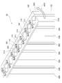
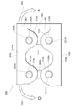
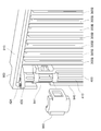
- FIG. 1 is a diagram illustrating an overall configuration of the shutter device according to the first embodiment.
- FIG. 2 is an enlarged view of a portion A in FIG.
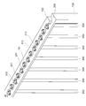
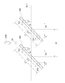
- FIG. 3 is a diagram illustrating the shutter device in a closed state.
- FIG. 4 is a diagram schematically showing the shape of the blade.
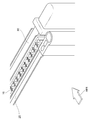
- FIG. 5 is a diagram illustrating a state in which the shutter device is disposed between the radiator and the condenser.
- FIG. 6 is a diagram showing the shape of the support portion formed at the end of the blade.
- FIG. 7 is a diagram for explaining a configuration of a portion where the blade is supported by the first frame and the second frame.
- FIG. 8 is a diagram for explaining a configuration of a portion where the blade is supported by the first frame and the second frame.
- FIG. 8 is a diagram for explaining a configuration of a portion where the blade is supported by the first frame and the second frame.
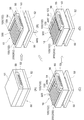
- FIG. 9 is a diagram illustrating a manufacturing process of the shutter device.
- FIG. 10 is a diagram for explaining the state of the shutter device inside the mold.
- FIG. 11 is a diagram illustrating a configuration of a shutter device according to the second embodiment.
- FIG. 12 is a diagram illustrating a state of the blade when the shutter device is fully closed.
- FIG. 13 is a diagram showing a state of the blade in the molding process.
- FIG. 14 is a diagram showing the shape of the support portion formed at the end of the blade.
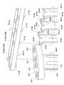
- FIG. 15 is a diagram illustrating a configuration of a shutter device according to the third embodiment.
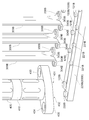
- FIG. 16 is an exploded view showing the structure of part B in FIG.
- FIG. 17 is an exploded view showing the structure of part C in FIG. FIG.
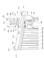
- FIG. 18 is a diagram illustrating a configuration of a shutter unit including a plurality of shutter devices of FIG.
- FIG. 19 is a diagram illustrating a configuration of a holding frame of the shutter unit.
- FIG. 20 is an exploded view showing the structure of part D in FIG.
- FIG. 21 is an exploded view showing the structure of part E in FIG.
- FIG. 22 is an exploded view showing the structure of part F in FIG.
- FIG. 23 is an exploded view showing the structure of part G in FIG.
- FIG. 24 is an exploded view showing the structure of part G in FIG.
- the configuration of the shutter device 10 according to the first embodiment will be described with reference to FIGS.
- the shutter device 10 is a device for temporarily blocking the flow of air flowing into the engine room from a front grill of a vehicle (not shown). As shown in FIG. 5, the shutter device 10 is disposed at a position between the condenser 20 and the radiator 30 in the front side portion of the vehicle.
- the condenser 20 is a part of an air conditioner provided in the vehicle.
- the condenser 20 is a heat exchanger for performing heat exchange between the refrigerant circulating in the refrigeration cycle and the air, thereby radiating heat from the refrigerant to the air.
- the radiator 30 is a heat exchanger for exchanging heat between the cooling water heated in the internal combustion engine of the vehicle and the air and thereby radiating heat from the cooling water to the air. 1 and 5, the flow of air introduced from the front grill into the engine room is indicated by an arrow AR1.
- the engine room when driving at high speeds or in winter, the engine room may be overcooled by the introduced air, which may reduce the fuel efficiency of the vehicle.
- the engine room in order to suppress the air resistance of the vehicle, it may be preferable to temporarily suppress the introduction of air into the engine room.
- the shutter device 10 has a state where the flow of air flowing into the engine room is blocked (hereinafter also referred to as “closed state”), and a state where the air flow is not blocked (hereinafter also referred to as “open state”). Can be switched. By such a switching operation of the shutter device 10, it is possible to temporarily suppress the inflow of air into the engine room.
- the arrangement shown in FIG. 5 is merely an example, and the position where the shutter device 10 is provided is not limited to the above.
- the shutter device 10 may be disposed at a position slightly downstream of the front grill.
- FIG. 1 shows the overall configuration of the shutter device 10 in the open state.
- FIG. 2 is an enlarged view of part A in FIG.
- the shutter device 10 includes a fixed frame 100, a movable frame 200, and a blade 300.
- the fixed frame 100 is a frame formed so as to be rectangular as a whole, and is a member for supporting a blade 300 described later in a rotatable state.
- the material of the fixed frame 100 is polyamide.
- As the material of the fixed frame 100 another resin may be used, or a metal such as aluminum may be used.
- the fixed frame 100 corresponds to the “first frame” in the present embodiment.
- the fixed frame 100 is fixed to, for example, a radiator or a capacitor.
- the fixed frame 100 may be directly fixed to the vehicle body. That is, it may be indirectly fixed to the vehicle body via another member, or may be directly fixed. That is, it is only necessary that the fixed frame 100 is fixed to the vehicle body side.
- the fixed frame 100 has an upper horizontal portion 110, vertical portions 130 and 140, and a lower horizontal portion 120.
- the upper horizontal portion 110 is a portion corresponding to the upper side of the rectangular fixed frame 100.
- the upper horizontal portion 110 is formed with a plurality of protrusions 111 (fixed-side protrusions) that protrude toward the movable frame 200 described later.
- the protrusions 111 are arranged at equal intervals along the longitudinal direction of the upper horizontal portion 110.
- An insertion hole 112 is formed in each protrusion 111.
- the insertion hole 112 is a through hole formed so as to penetrate the protruding portion 111 in the vertical direction.
- the first support portion 301 formed on the blade 300 is inserted into the insertion hole 112 from below. That is, the upper horizontal portion 110 is a portion that supports the first support portion 301 in the fixed frame 100.
- the vertical portion 130 is a portion extending from one end side of the upper horizontal portion 110 toward the lower side.
- the vertical portion 140 is a portion extending from the other end side of the upper horizontal portion 110 toward the lower side.
- the vertical portion 130 and the vertical portion 140 are portions corresponding to the right side and the left side of the rectangular fixed frame 100. Both the vertical part 130 and the vertical part 140 connect the upper horizontal part 110 and the lower horizontal part 120.
- the lower horizontal portion 120 is a portion corresponding to the lower side of the rectangular fixed frame 100.
- the lower end of the vertical portion 130 is connected to one end side of the lower horizontal portion 120, and the lower end of the vertical portion 140 is connected to the other end side of the lower horizontal portion 120.
- the shape of the lower horizontal portion 120 is substantially the same as the shape of the upper horizontal portion 110.
- the lower horizontal portion 120 is formed with a protruding portion (details not shown) having the same shape as the protruding portion 111 of the upper horizontal portion 110.
- an insertion hole (not shown in detail) having the same shape as the insertion hole 112 of the upper horizontal portion 110 is formed in the protruding portion.
- a third support portion 303 (see FIG. 4) formed at the lower end portion of the blade 300 is inserted into the insertion hole from above. That is, the lower horizontal portion 120 is a portion that supports the third support portion 303 in the fixed frame 100.
- the shape of the portion of the lower horizontal portion 120 that supports the blade 300 from below is equal to the shape of the upper horizontal portion 110 shown in FIG. Therefore, in the following description, the protruding portion (fixed-side protruding portion) formed on the lower horizontal portion 120 is referred to as a “projecting portion 111” as in the case of the upper horizontal portion 110. Further, the insertion hole formed in the protruding portion 111 of the lower horizontal portion 120 is referred to as “insertion hole 112” as in the case of the upper horizontal portion 110.
- the movable frame 200 is a frame body that is formed in a rectangular shape as in the fixed frame 100, and is a member that supports the blade 300 in a rotatable state.
- the movable frame 200 is formed to have substantially the same shape as the fixed frame 100, and is disposed so as to face the fixed frame 100 with the blade 300 interposed therebetween.
- the movable frame 200 is formed of the same material (polyamide) as the fixed frame 100.
- the material of the movable frame 200 another resin may be used, or a metal such as aluminum may be used.
- a material different from the material of the fixed frame 100 may be used.
- the movable frame 200 corresponds to the “second frame” in the present embodiment.
- the movable frame 200 is not fixed to the vehicle body side.
- the movable frame 200 is rotatably connected to a second support portion 302 (described later) of each blade 300. For this reason, the movable frame 200 can be moved relative to the fixed frame 100. As will be described later, the opening and closing of the shutter device 10 is switched by moving the movable frame 200.
- the movable frame 200 has an upper horizontal portion 210, vertical portions 230 and 240, and a lower horizontal portion 220.
- the upper horizontal portion 210 is a portion corresponding to the upper side of the rectangular movable frame 200.
- the length of the movable frame 200 is the same as the length of the fixed frame 100.
- the upper horizontal portion 210 is formed with a plurality of protrusions 211 (movable side protrusions) that protrude toward the fixed frame 100.
- the protrusions 211 are arranged at equal intervals along the longitudinal direction of the upper horizontal portion 210. Further, when the shutter device 10 is in the open state as shown in FIG. 2, the position of each protrusion 211 is a position facing the protrusion 111 along the air flow direction (arrow AR1). .
- An insertion hole 212 is formed in each protrusion 211.
- the insertion hole 212 is a through hole formed so as to penetrate the protruding portion 211 in the vertical direction.
- the second support portion 302 formed on the blade 300 is inserted into the insertion hole 212 from below. That is, the upper horizontal portion 210 is a portion that supports the second support portion 302 in the movable frame 200.
- the vertical portion 230 is a portion extending from one end side of the upper horizontal portion 210 toward the lower side.
- the vertical portion 240 is a portion extending from the other end side of the upper horizontal portion 210 toward the lower side.
- the vertical portion 230 and the vertical portion 240 are portions corresponding to the right side and the left side of the rectangular movable frame 200.
- the vertical portion 230 and the vertical portion 240 both connect the upper horizontal portion 210 and the lower horizontal portion 220.
- the lengths of the vertical part 230 and the vertical part 240 are the same as the lengths of the vertical part 130 and the vertical part 140.
- the lower horizontal portion 220 is a portion corresponding to the lower side of the rectangular movable frame 200.
- the lower end of the vertical portion 230 is connected to one end side of the lower horizontal portion 220, and the lower end of the vertical portion 240 is connected to the other end side of the lower horizontal portion 220.
- the shape of the lower horizontal portion 220 is substantially the same as the shape of the upper horizontal portion 210.
- the lower horizontal portion 220 is formed with a protruding portion (details not shown) having the same shape as the protruding portion 211 of the upper horizontal portion 210.
- an insertion hole (not shown in detail) having the same shape as the insertion hole 212 of the upper horizontal portion 210 is formed in the protruding portion.
- the 4th support part 304 (refer FIG. 4) formed in the lower end part of the braid
- the protruding portion (movable side protruding portion) formed on the lower horizontal portion 220 is referred to as a “projecting portion 211” as in the case of the upper horizontal portion 210.
- the insertion hole formed in the protruding portion 211 of the lower horizontal portion 220 is referred to as “insertion hole 212” as in the case of the upper horizontal portion 210.
- the blade 300 is a plate-like member formed so that its main surface is substantially rectangular, and a plurality of blades 300 are provided in the shutter device 10.
- the blade 300 is formed of the same material (polyamide) as the fixed frame 100 or the like.
- As the material of the blade 300 another resin may be used, or a metal such as aluminum may be used.
- a material different from the material of the fixed frame 100 and the movable frame 200 may be used.
- the longitudinal direction of each blade 300 is in the vertical direction, but the longitudinal direction of each blade 300 is in the left-right direction (horizontal direction). It may be.
- the effect of the shutter device 10 described below is the same regardless of the direction in which the longitudinal direction of each blade 300 is aligned.
- each blade 300 is the same as each other.
- Each blade 300 is supported by the fixed frame 100 and the movable frame 200 in a state where the longitudinal direction thereof is along the longitudinal direction of the vertical portion 130 and the like.
- FIG. 4 is a diagram schematically showing the blade 300 as viewed from a direction perpendicular to the main surface.
- a first support portion 301 and a second support portion 302 are formed on one end side (upper end side) in the longitudinal direction of the blade 300.
- a third support portion 303 and a fourth support portion 304 are formed on the other end side (lower end side) in the longitudinal direction of the blade 300.
- the first support portion 301 and the second support portion 302 are protrusions formed so as to protrude further upward from the upper end surface of the blade 300.
- the shapes of the first support portion 301 and the second support portion 302 are shown in a simplified manner. Specific shapes of the first support portion 301 and the like will be described later with reference to FIG.
- the first support portion 301 and the second support portion 302 are formed so as to be aligned along the short direction of the blade 300 (the left-right direction in FIG. 4).
- the first support portion 301 is a portion that is inserted from below into the insertion hole 112 of the upper horizontal portion 110.
- the blade 300 is supported so as to be rotatable with respect to the fixed frame 100.
- the second support portion 302 is a portion that is inserted from below into the insertion hole 212 of the upper horizontal portion 210.
- the blade 300 is supported so as to be rotatable with respect to the movable frame 200.
- the third support portion 303 and the fourth support portion 304 are protrusions formed so as to protrude further downward from the lower end surface of the blade 300.
- the shapes of the third support portion 303 and the fourth support portion 304 are also shown in a simplified manner. Specific shapes of the third support portion 303 and the fourth support portion 304 are equal to a shape obtained by vertically inverting the shape of the first support portion 301 described later.
- 3rd support part 303 and 4th support part 304 are formed so that it may line up along the transversal direction (left-right direction in Drawing 4) of blade 300.
- the third support portion 303 is formed at a position directly below the first support portion 301 along the longitudinal direction of the blade 300 (vertical direction in FIG. 4). For this reason, the central axis of the third support portion 303 coincides with the central axis of the first support portion 301.
- the fourth support portion 304 is formed at a position directly below the second support portion 302 along the longitudinal direction of the blade 300. For this reason, the central axis of the fourth support part 304 coincides with the central axis of the second support part 302.
- the third support portion 303 is a portion that is inserted from above into the insertion hole 112 of the lower horizontal portion 120.
- the blade 300 is supported so as to be rotatable with respect to the fixed frame 100.
- the fourth support portion 304 is a portion that is inserted from above into the insertion hole 212 of the lower horizontal portion 220.
- the blade 300 is supported so as to be rotatable with respect to the movable frame 200.
- each blade 300 In the open state shown in FIG. 2, the normal direction of each blade 300 is parallel to the longitudinal direction of the upper horizontal portion 110 and the like. For this reason, the size of the gap formed between adjacent blades 300, that is, the cross-sectional area of the flow path through which air passes is maximized.
- each blade 300 changes its normal direction while maintaining a parallel state. Thereby, the cross-sectional area of the flow path through which air passes gradually becomes smaller.
- the blades 300 adjacent to each other are in a state in which the end portions in the short direction (that is, the vicinity of the long side) are brought into contact with each other.
- the shutter device 10 is in a closed state.
- the blades 300 rotate around the rotation axis along the longitudinal direction thereof so that the air flow is blocked (closed state in FIG. 3) and the air flow is not blocked (FIG. 3). 2), and functions as a member for switching.
- the central axes of the first support part 301 and the third support part 303 correspond to the “rotation axis” described above.
- the opening / closing operation of the shutter device 10 is realized by an unillustrated actuator provided in the vehicle moving the movable frame 200 (that is, moving the movable frame 200 relative to the fixed frame 100). Thereby, the flow rate of the air flowing into the engine room is adjusted.
- the shutter device 10 configured as described above, not all the blades 300 are supported by a single frame, but all the blades 300 are supported by both the fixed frame 100 and the movable frame 200. In other words, the fixed frame 100 and the movable frame 200 are bridged and connected by the plurality of blades 300. For this reason, even if the dimension in the short direction of each blade 300 is reduced, the rigidity of the entire shutter device 10 does not deteriorate excessively.
- FIG. 6 is a perspective view illustrating an enlarged shape of the first support portion 301 and the vicinity thereof.
- FIG. 7 is a diagram illustrating a part of the shutter device 10 (in the vicinity of the first support portion 301) in the open state as viewed from above.
- the first support portion 301 has a cylindrical portion 310 and a retaining portion 320.
- the cylindrical portion 310 is a portion formed so as to extend upward (along the longitudinal direction of the blade 300) from the upper end surface 309 of the blade 300.
- the cylindrical portion 310 has a cylindrical shape whose central axis is perpendicular to the upper end surface 309.
- the retaining portion 320 is a portion formed so as to extend further upward from the upper surface 311 of the cylindrical portion 310.
- the retaining portion 320 has a pair of projecting portions 330 and 340. These protrusions 330 and 340 are formed so as to extend from the substantially cylindrical portion formed in the central portion of the retaining portion 320 to both sides along the short direction of the blade 300.
- the protruding portions 330 and 340 protrude beyond the edge of the circular upper end surface 309 toward the radially outer side. For this reason, the lower surface 332 of the protrusion 330 and the upper end surface 309 of the blade 300 are opposed to each other. Similarly, the lower surface 332 of the protrusion 330 and the upper end surface 309 of the blade 300 face each other.
- the distance (L21) from the lower surface 332 to the upper end surface 309 is the thickness of the upper horizontal portion 110, specifically, the thickness of the protruding portion 113 (the portion facing the upper end surface 309). It is slightly larger than L22).
- the distance (L21) from the lower surface 342 to the upper end surface 309 is slightly smaller than the thickness of the upper horizontal portion 110, specifically, the thickness (L22) of the protruding portion 114 that is the portion facing the upper end surface 309. Is getting bigger.
- a protrusion 341 is formed at the tip of the protrusion 340 and at the lower end of the side surface.
- the protrusion 341 is formed at a position that becomes the right end portion of the protrusion 340 when the tip is viewed from the front.
- the lower end surface of the protrusion 341 is on the same plane as the lower surface 342.
- a protrusion 331 is formed at the tip of the protrusion 330 and at the lower end of the side surface (not shown in FIG. 6, see FIG. 7).
- the protrusion 331 is formed at a position that becomes the right end portion of the tip portion of the protrusion 330 when the tip portion is viewed from the front. That is, the protrusion 331 and the protrusion 341 are formed at positions that are symmetrical with each other around the central axis of the cylindrical portion 310.
- the lower end surface of the protrusion 331 is on the same plane as the lower surface 332.
- the insertion hole 112 formed in the protruding portion 111 is a substantially circular through hole, but two opposing portions of the edge protrude toward the first support portion 301.
- the shape is like this.
- Two portions of the edge of the insertion hole 112 protruding as described above are shown as protruding portions 113 and 114 in FIG.
- the tip of the protrusion 113 and the tip of the protrusion 114 support the cylindrical portion 310 from the side surface.
- the upper surface of the protruding portion 113 formed on the fixed frame 100 is in contact with the lower surface 332 of the protruding portion 330 formed on the first support portion 301. Further, the lower surface of the protrusion 113 formed on the fixed frame 100 is in contact with the upper end surface 309 of the blade 300. Similarly, the upper surface of the protruding portion 114 formed on the fixed frame 100 is in contact with the lower surface 342 of the protruding portion 340 formed on the first support portion 301. Further, the lower surface of the protrusion 114 formed on the fixed frame 100 is in contact with the upper end surface 309 of the blade 300.
- a protrusion 131 protruding upward is formed on the upper surface of the protrusion 113 formed on the fixed frame 100.
- the protrusion 131 is formed at a position where the protrusion 131 contacts the protrusion 331 formed on the first support portion 301 from the side (right side in FIG. 7) when the shutter device 10 is in the open state of FIG. Yes.
- a protrusion 141 protruding upward is formed on the upper surface of the protrusion 114 formed on the fixed frame 100.
- the protrusion 141 is formed at a position where the protrusion 141 contacts the protrusion 341 formed on the first support portion 301 from the side (left side in FIG. 7) when the shutter device 10 is in the open state of FIG. Yes.
- the movable frame 200 cannot be moved in the direction of the arrow AR4 from the state of FIG. That is, after changing the rotation angle of the blade 300 from the closed state shown in FIG. 3 to the state shown in FIG. 7 (the shutter device 10 is fully open), the rotation angle is changed in the same direction (indicated by the arrow AR4). It can no longer be changed toward (direction).
- the protrusion 131, the protrusion 331, the protrusion 141, and the protrusion 341 function as a stopper mechanism for suppressing the rotation angle of the blade 300 from changing too much as described above.
- the shape of the second support portion 302 is the same as the shape of the first support portion 301 shown in FIGS. 6, 7, and 14. Therefore, in the following description, the cylindrical portion formed in the lower portion of the second support portion 302 is referred to as a “cylindrical portion 310” as in the case of the first support portion 301. Further, the pair of protrusions formed on the second support part 302 are referred to as “protrusion part 330” and “protrusion part 340” as in the case of the first support part 301. Further, the pair of protrusions formed on the second support portion 302 are referred to as “projections 331” and “projections 341” as in the case of the first support portion 301.
- the shape of the insertion hole 212 formed in the movable frame 200 is the same as the shape of the insertion hole 112 formed in the fixed frame 100.
- the part corresponding to the protrusion 113 of the insertion hole 112 is hereinafter referred to as “protrusion 213”.
- a portion corresponding to the protrusion 114 of the insertion hole 112 in the shape of the edge of the insertion hole 212 is hereinafter referred to as a “protrusion 214”.
- the upper surface of the protruding portion 213 formed on the movable frame 200 is in contact with the lower surface of the protruding portion 330 formed on the second support portion 302. Further, the lower surface of the protruding portion 213 formed on the movable frame 200 is in contact with the upper end surface 309 of the blade 300. Similarly, the upper surface of the protruding portion 214 formed on the movable frame 200 is in contact with the lower surface of the protruding portion 340 formed on the second support portion 302. Further, the lower surface of the protrusion 214 formed on the movable frame 200 is in contact with the upper end surface 309 of the blade 300.
- a protrusion 231 protruding upward is formed on the upper surface of the protrusion 213 formed on the movable frame 200.
- the protrusion 231 is formed at a position where the protrusion 231 comes into contact with the protrusion 331 formed on the second support portion 302 from the side (right side in FIG. 7) when the shutter device 10 is in the open state of FIG. Yes.
- a protrusion 241 protruding upward is formed on the upper surface of the protrusion 214 formed on the movable frame 200.
- the protrusion 241 is formed at a position so as to come into contact with the protrusion 341 formed on the second support portion 302 from the side (left side in FIG. 7) when the shutter device 10 is in the open state of FIG. Yes.
- the movable frame 200 is moved in the direction of the arrow AR4 from the state of FIG. 7 also by interference between the projection 231 and the projection 331 of the second support portion 302 and interference between the projection 241 and the projection 341 of the second support portion 302. Is no longer possible.
- the protrusion 231, the protrusion 331 of the second support part 302, the protrusion 241, and the protrusion 341 of the second support part 302 function as a stopper mechanism for suppressing the rotation angle of the blade 300 from changing too much as described above. .
- the protrusions formed as the stopper mechanism are formed on all support parts (first support part 301A, second support part 302A, third support part 303A, and fourth support part 304A) as in this embodiment. However, it may be formed only in a part of the support portions. Further, the projection 331 and the projection 341 may be formed only on some blades 300. That is, a mode in which blades 300 having no protrusions 331 or the like are mixed may be used.
- the shape of the portion of the lower horizontal portion 120 that supports the blade 300 from below is equal to the shape of the upper horizontal portion 110 shown in FIGS. Further, the shape of the portion of the lower horizontal portion 220 that supports the blade 300 from below is equal to the shape of the upper horizontal portion 210 shown in FIGS. Further, the shapes of the third support portion 303 and the fourth support portion 304 are equal to those obtained by vertically inverting the shapes of the first support portion 301 and the second support portion 302 shown in FIGS.
- the structure of the portion where the third support portion 303 is supported by the fixed frame 100 is the same as the structure of the portion where the first support portion 301 is supported by the fixed frame 100.
- the structure of the portion where the fourth support portion 304 is supported by the movable frame 200 is the same as the structure of the portion where the third support portion 303 is supported by the movable frame 200. For this reason, detailed illustration and description of these structures are omitted.
- a point at the tip of the protruding portion 111 (fixed side protruding portion) is shown as a point P11. Moreover, the point used as the bottom of the recessed part formed between the adjacent protrusion parts 111 is shown as the point P12. Similarly, a point at the tip of the protruding portion 211 (movable side protruding portion) is indicated as a point P22. Moreover, the point used as the bottom of the recessed part formed between the adjacent protrusion parts 211 is shown as the point P21.
- the protrusion 113 of the fixed frame 100 does not exist below the protrusion 330 of the first support 301 (the back side of the drawing). Further, the protrusion 114 of the fixed frame 100 does not exist below the protrusion 340 of the first support portion 301.
- the protruding portion 213 of the movable frame 200 does not exist on the lower side of the protruding portion 330 of the second support portion 302. Further, the protrusion 214 of the movable frame 200 does not exist below the protrusion 340 of the second support portion 302.
- the first support portion 301 and the second support portion 302 can be detached from the fixed frame 100 and the movable frame 200 by moving the blade 300 downward.
- the third support portion 303 and the fourth support portion 304 can be detached from the fixed frame 100 and the movable frame 200 by moving the blade 300 upward.
- the rotation angle of each blade 300 in the state of FIG. 8 is hereinafter also referred to as “insertion angle”.
- the rotation angle of the blade 300 is the insertion angle
- either the blade 300 can be detached from the fixed frame 100 or the blade 300 can be detached from the movable frame 200.
- the rotation angle of the blade 300 is different from the insertion angle
- the blade 300 is detached from the fixed frame 100 and the blade 300 is moved to the movable frame 200. It is impossible to detach from.
- FIG. 12 schematically shows the state of the blade 300 when the shutter device 10 is fully closed.
- FIG. 12 is a diagram illustrating two blades 300 adjacent to each other as seen along their respective longitudinal directions.
- L1 the length in the short direction of the blade 300 is shown as L1.
- L2 the distance between the centers of the blades 300 adjacent to each other is indicated as L2.
- L1 is longer than L2.
- each component (the fixed frame 100, the movable frame 200, and the blade 300) constituting the shutter device 10 is formed by resin injection molding. Injection molding is performed using a mold 50.
- the molding die 50 includes an upper die 51, a first lower die 52, a second lower die 53, a first slide die 54, a second slide die 55, a third slide die 56, and a fourth slide die 57. (Not shown in FIG. 9, refer to FIG. 10). In FIG. 9, the entire mold 50 is not shown, but only a part of the mold 50 is shown. Specifically, only the portion for molding the lower side of the shutter device 10 is shown.
- FIG. 9 (A) shows a state where the injection molding of the shutter device 10 is performed in the assembled mold 50. At this time, in the mold 50, the fixed frame 100, the movable frame 200, and the blade 300 are molded at a time. That is, FIG. 9A shows a state in which the molding process is performed in the manufacturing process of the shutter device 10.
- FIG. 10A schematically shows the arrangement of the components of the fixed frame 100, the movable frame 200, and the blade 300 in FIG. 9A in a top view.
- the movable frame 200 is drawn with a dotted line, and the other parts are drawn with a solid line.
- FIG. 10 also schematically shows a part of the mold 50 (the third slide mold 56 and the fourth slide mold 57).
- the fixed frame 100 when the molding process is being performed, the fixed frame 100 is in a state of being divided into two parts (an upper frame 101 and a lower frame 102).
- the upper frame 101 is a part including the upper horizontal part 110 in the fixed frame 100 and is an upper part in use.
- the lower frame 102 is a portion including the lower horizontal portion 120 of the fixed frame 100 and is a portion on the lower side when in use.
- the upper frame 101 and the lower frame 102 are separated from each other along the longitudinal direction of the vertical portion 130 (the vertical direction in FIG. 10A).
- the movable frame 200 is also divided into two parts (an upper frame 201 and a lower frame 202).
- the upper frame 201 is a part including the upper horizontal part 210 in the movable frame 200 and is an upper part in use.
- the lower frame 202 is a portion including the lower horizontal portion 220 of the movable frame 200 and is a portion on the lower side when in use.
- the upper frame 201 and the lower frame 202 are in a state of being separated from each other along the longitudinal direction of the vertical portion 230 (the vertical direction in FIG. 10A).
- the end surface of the vertical portion 130 of the upper frame 101 is shown as an end surface 101S
- the end surface of the vertical portion 140 of the upper frame 101 is shown as an end surface 103S
- an end surface of the vertical portion 130 of the lower frame 102 is shown as an end surface 102S
- an end surface of the vertical portion 140 of the lower frame 102 is shown as an end surface 104S.
- the end surface of the vertical portion 230 of the upper frame 201 is shown as an end surface 201S
- the end surface of the vertical portion 240 of the upper frame 201 is shown as an end surface 203S
- the end surface of the vertical portion 230 of the lower frame 202 is shown as an end surface 202S
- the end surface of the vertical portion 240 of the lower frame 202 is shown as an end surface 204S.
- the end surface 101S and the end surface 102S are opposed to each other, and the end surface 103S and the end surface 104S are opposed to each other. Further, the end surface 201S and the end surface 202S face each other, and the end surface 203S and the end surface 204S face each other.
- the distance between the end face 101S and the end face 102S, the distance between the end face 103S and the end face 104S, the distance between the end face 201S and the end face 202S, and the distance between the end face 203S and the end face 204S are all equal.
- the above distance is shown as G20.
- the distance between the end surface of the blade 300 (upper end surface 309 in FIG. 6) and the upper horizontal portion 110, the distance between the end surface of the blade 300 and the lower horizontal portion 120, the end surface of the blade 300 and the upper horizontal portion 210, And the distance between the end face of the blade 300 and the lower horizontal portion 220 are all equal.
- the above distance is shown as G10.
- G20 is twice as long as G10.
- the positional relationship between the fixed frame 100 and the movable frame 200 is as shown in FIG. That is, the movable frame 200 is offset with respect to the fixed frame 100 so that the protruding portion 111 of the fixed frame 100 and the protruding portion 211 of the movable frame 200 do not overlap in the vertical direction.
- the fixed frame 100 disposed on the upper side is offset to the right with respect to the movable frame 200 disposed on the lower side.
- Each blade 300 is formed in a state of being arranged in a line between the upper frame 101 and the lower frame 102 and between the upper frame 201 and the lower frame 202.
- the arrangement of the blades 300 at this time is in the state shown in FIG. Specifically, the normal direction of the main surface of each blade 300 is inclined by 45 degrees with respect to the longitudinal direction of the upper horizontal portion 110 and the like (left and right direction in FIG. 8). That is, the rotation angle of each blade 300 is the “insertion angle” described above.
- the first support portion 301 overlaps the insertion hole 112 of the upper horizontal portion 110, and the second support portion 302 and the insertion hole 212 of the upper horizontal portion 210. overlapping.
- the third support portion 303 overlaps with the insertion hole 112 of the lower horizontal portion 120, and the fourth support portion 304 overlaps with the insertion hole 212 of the lower horizontal portion 220.
- the first support portion 301 is not inserted through the insertion hole 112.
- the second support 302, the third support 303, and the fourth support 304 are the same applies to the second support 302, the third support 303, and the fourth support 304. Therefore, as shown in FIG. 10A, the fixed frame 100 and the blade 300 do not overlap when viewed from above. Similarly, the movable frame 200 and the blade 300 do not overlap.
- FIG. 13 schematically shows the state of the blade 300 in the molding process.
- FIG. 13 is a diagram illustrating two blades 300 adjacent to each other as seen along their respective longitudinal directions.
- an arrow AR8 indicates the longitudinal direction of the blade 300 (the depth direction in FIG. 13) and the direction in which the plurality of blades 300 are arranged (the direction in which the dotted line DL1 in FIG. 13 extends). Is also a vertical direction. That is, it is the same direction as arrow AR8 which shows the air flow direction in FIG.
- the insertion angle is indicated as “ ⁇ ”.
- a plane indicated by a dotted line DL1 in FIG. 13 is a boundary surface (that is, a parting surface) between the upper mold 51 of the molding die 50 and a lower side portion thereof (second lower mold 53, first slide mold 54). ) Is parallel to the surface.
- the arrow AR8 shown in FIG. 8 can also be said to be a direction perpendicular to this parting surface.
- L1 and L2 are defined as in the case of FIG. 12, in this embodiment, L1 ⁇ cos ⁇ is smaller than L2.
- L1 ⁇ cos ⁇ is smaller than L2.
- the diameter of the first support portion 301 and the like, specifically, the diameter of the cylindrical portion 310 is shown as d in FIG. Further, the distance (center distance) between the first support portion 301 and the second support portion 302 formed on the same blade 300 is indicated as L11 in FIG. In this embodiment, L11 ⁇ cos ⁇ is larger than d.
- L11 ⁇ cos ⁇ is larger than d.
- the first support portion 301 and the second support portion 302 do not overlap, and a gap G2 is formed between them.
- the third support portion 303 and the fourth support portion 304 do not overlap with each other, and a gap G2 is formed between them. Since the blade 300 and the like are molded in such a state, the mold and the first support portion 301 and the like do not interfere with each other during die cutting.
- FIG. 9B When the molding process is completed, as shown in FIG. 9B, the upper mold 51 moves upward, and the first lower mold 52 moves downward (in the direction of arrow AR5). Thereby, the shaping
- the third slide mold 56 moves in the direction of the arrow AR6.
- the third slide mold 56 is a part for molding the fixed frame 100 and the movable frame 200 in the molding process.
- the third slide die 56 is in a state of holding the lower horizontal part 120 of the fixed frame 100 and the lower horizontal part 220 of the movable frame 200 after the molding process is completed.
- An arrow AR6 in FIG. 9C is a direction along the longitudinal direction of the blade 300 and is a direction in which the lower horizontal portion 120 and the like are directed toward the blade 300.
- the third slide mold 56 moves in the direction of the arrow AR6, the lower horizontal portion 120 and the lower horizontal portion 220 both move toward the blade 300 side.
- the third support portion 303 is inserted into the insertion hole 112 of the lower horizontal portion 120
- the fourth support portion 304 is inserted into the insertion hole 212 of the lower horizontal portion 220.
- the fourth slide mold 57 is a part for molding the fixed frame 100 and the movable frame 200 in the same manner as the third slide mold 56, and is an upper horizontal part. 110 and a mold member that holds the upper horizontal portion 210.
- the fourth slide mold 57 moves in the direction opposite to the arrow AR6.
- both the upper horizontal portion 110 and the upper horizontal portion 210 move toward the blade 300 side.
- the first support portion 301 is inserted into the insertion hole 112 of the upper horizontal portion 110
- the second support portion 302 is inserted into the insertion hole 212 of the upper horizontal portion 210.
- FIG. 9C shows a state in which the assembly process is performed in the manufacturing process of the shutter device 10.
- FIG. 10B schematically shows a state where the assembly process of FIG. 9C has been completed in the same manner as in FIG. 10A.
- a projection (not shown) with a retaining mechanism is formed on the end surface 101S, and a recess into which the projection is inserted is formed on the end surface 102S.
- the projection of the end surface 101S is inserted into the recess of the end surface 102S, and both are snap-connected. For this reason, in the state of FIG. 10B, the end surface 101S and the end surface 102S are in contact with each other, and the vertical portion 130 is integrated in this portion.
- the snap connection as described above is similarly performed between the end surface 103S and the end surface 104S, between the end surface 201S and the end surface 202S, and between the end surface 203S and the end surface 204S. Therefore, in the state of FIG. 10B, the upper frame 101 and the lower frame 102 are integrated, and the upper frame 201 and the lower frame 202 are integrated.
- the third slide mold 56 and the fourth slide mold 57 are returned to their original positions. Subsequently, as shown in FIG. 9D, the first slide mold 54 moves in the direction of the arrow AR7.
- the first slide die 54 is a portion for forming the vertical portion 130 of the fixed frame 100 in the forming step. Such a first slide mold 54 is in a state of holding the vertical portion 130 in the fixed frame 100 after the time when the molding process is completed.
- An arrow AR7 in FIG. 9D is a direction along the longitudinal direction of the lower horizontal portion 120, and is a direction in which the vertical portion 130 is directed to a position directly above the vertical portion 230.
- FIG. 9D shows a state where the rotation process is performed in the manufacturing process of the shutter device 10.
- the rotation angle of each blade 300 is an insertion angle (FIG. 8).
- the rotation angle of each blade 300 is different from the insertion angle (FIG. 7). For this reason, when the rotation process is completed, the blade 300 cannot be removed from the fixed frame 100 or the movable frame 200 by moving in the longitudinal direction.
- the protrusions 331 and 341 formed on the first support portion 301 get over the protrusions 131 and 141 formed on the fixed frame 100, respectively.
- the protrusions 331 and 341 formed on the second support portion 302 get over the protrusions 231 and 241 formed on the movable frame 200, respectively.
- the fixed frame can be moved in the direction of the arrow AR3 in FIG. 7, but cannot be moved in the direction of the arrow AR4.
- the shutter device 10 is taken out from the mold 50.
- a part of the mold 50 is moved to assemble the plurality of blades 300 to the fixed frame 100 and to assemble the plurality of blades 300 to the movable frame 200. Can be completed at once.
- the second embodiment will be described with reference to FIG.
- the shutter device 10A according to the second embodiment is different from the first embodiment in the configuration of the portion where the fixed frame 100A and the movable frame 200A support the blade 300A and the configuration of the stopper mechanism.
- Other configurations are the same as those of the first embodiment. Below, it demonstrates only in a different point from 1st Embodiment, The description is abbreviate
- the four support portions (the first support portion 301A, the second support portion 302A, the third support portion 303A, and the fourth support portion 304A) formed on the blade 300A are all simple cylinders. It has a shape.
- the shapes of the insertion holes 112 through which the respective support portions are inserted are all simple circles.
- FIG. 11 only the support structure in the first support portion 301A and the second support portion 302A is shown.
- the support structure in the third support part 303A and the fourth support part 304A is the same as the support structure shown in FIG.
- the first support portion 301A and the like are only rotatably supported by the fixed frame 100A and the movable frame 200A, and a mechanism for preventing the removal such as the protruding portion 330 is not formed. .
- the fixed frame 100A and the movable frame 200A are bridged and connected by the plurality of blades 300A. For this reason, there exists the same effect (improvement of rigidity) as a 1st embodiment.
- the upper horizontal portion 110A when the upper horizontal portion 110A is made thin, there is a concern that the first support portion 301A may be detached from the upper horizontal portion 110 as the upper horizontal portion 110A bends. For this reason, when the rigidity of the upper horizontal portion 110A is low, it is desirable to form a mechanism for preventing the disconnection as in the first embodiment.
- a stopper 160 is formed at a position that is an end of the fixed frame 100A on the vertical portion 140 side (right side in FIG. 11).
- the stopper 160 is a plate-like member formed so as to extend from the fixed frame 100A toward the movable frame 200A side (upper side in FIG. 11).
- the shutter device 10A is in the open state as shown in FIG. 11, the surface 161 on the blade 300A side of the stopper 160 is in contact with the side surface 261 of the movable frame 200A. Therefore, the movable frame 200A can move in the direction of the arrow AR3, but the movable frame 200A cannot move in the direction of the arrow AR4 by the stopper 160.
- the stopper 160 suppresses the change in the rotation angle of the blade 300 by suppressing the movement of the movable frame 200A. That is, the stopper 160 functions as a stopper mechanism similar to the protrusion 131, the protrusion 141, the protrusion 231, the protrusion 241, the protrusion 331, and the protrusion 341 in the first embodiment.
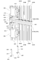
- FIG. 15 shows the overall configuration of the shutter device 10B according to the third embodiment.
- FIG. 16 is an exploded view showing the structure of part B in FIG.
- FIG. 17 is an exploded view showing the structure of part C in FIG.
- the shutter device 10B includes a blade 300B, a second frame 200B, a first frame 100B, and a connecting member 400.
- the blade 300B is a plate-like member formed so that its main surface is substantially rectangular, and a plurality of blades 300B are provided in the shutter device 10B.
- the blade 300B has the same function as the blade 300 of the first embodiment. That is, the blade 300B functions as a member for switching between a state in which the air flow is interrupted and a state in which the air flow is not interrupted by rotating about the rotation axis along the longitudinal direction thereof. It is. 15 to 17 show a state where each blade 300B is parallel to the air passage direction, that is, a state where the shutter device 10B is fully opened.
- a first support portion 301B and a second support portion 302B are formed on one end side (upper end side) in the longitudinal direction of the blade 300B.
- the third support portion 303 ⁇ / b> B and the fourth support portion 304 ⁇ / b> B are formed on the other end side (lower end side) of the blade 300 in the longitudinal direction.
- the first support portion 301B extends from a portion of the blade 300B that faces an upper horizontal portion 110B (described later) in a direction perpendicular to the main surface of the blade 300B. Is formed. A circular through hole 310B is formed in the first support portion 301B so as to penetrate in the vertical direction.
- the first support portion 301B is a portion that is rotatably supported by the upper horizontal portion 110B of the first frame 100B.
- the second support portion 302B extends from a portion of the blade 300B facing an upper horizontal portion 210B described later (portion on the front side in FIG. 16) in a direction opposite to the direction in which the first support portion 301B extends. It is formed as follows. A circular through hole 320B is formed in the second support portion 302B so as to penetrate in the vertical direction. The second support portion 302B is a portion that is rotatably supported by the upper horizontal portion 210B of the second frame 200B.
- the third support portion 303B extends from a portion of the blade 300B that faces a lower horizontal portion 120B described later (portion on the back side in FIG. 17) in one direction perpendicular to the main surface of the blade 300B. Is formed.
- the direction in which the third support portion 303B extends is the same as the direction in which the first support portion 301B extends. That is, the third support portion 303B is formed at a position on the lower side of the first support portion 301B.
- a circular through hole 330B is formed in the third support portion 303B so as to penetrate in the vertical direction.
- the third support portion 303B is a portion that is rotatably supported by the lower horizontal portion 120B of the first frame 100B.
- the fourth support portion 304B extends from a portion of the blade 300B facing a lower horizontal portion 220B described later (a portion on the front side in FIG. 17) toward one direction perpendicular to the main surface of the blade 300B. Is formed.
- the direction in which the fourth support portion 304B extends is the same as the direction in which the second support portion 302B extends. That is, the fourth support portion 304B is formed at a position on the lower side of the second support portion 302B.
- a circular through hole 340B is formed in the fourth support portion 304B so as to penetrate in the vertical direction.
- the fourth support portion 304B is a portion that is rotatably supported by the lower horizontal portion 220B of the second frame 200B.
- the second frame 200B has the same function as the movable frame 200 of the first embodiment, and is a member for supporting each blade 300B in a rotatable state.
- the second frame 200B has an upper horizontal portion 210B and a lower horizontal portion 220B.
- the upper horizontal portion 210B and the lower horizontal portion 220B are provided as separate members. That is, the second frame 200B is divided into an upper horizontal portion 210B and a lower horizontal portion 220B.
- the upper horizontal portion 210B of the second frame 200B is a rod-like member arranged along the upper end portion of each blade 300B, similarly to the upper horizontal portion 210 in the first embodiment.
- a plurality of protrusions 211B are formed on the surface (lower surface) of the upper horizontal portion 210B that faces the blade 300B.
- Each protrusion 211B has a cylindrical shape, and its central axis is along the longitudinal direction of the blade 300B.
- Each protrusion 211B is formed at a position facing the through hole 320B of each blade 300B.
- the outer diameter of the protrusion 211B is slightly smaller than the inner diameter of the through hole 320B. As shown in FIG.
- the protrusion 211B is inserted from above into the through hole 320B in a state in which the central axis thereof coincides with the central axis of the through hole 320B. Thereby, each 2nd support part 302B is rotatably supported by the upper horizontal part 210B.
- the lower horizontal portion 220B of the second frame 200B is a rod-like member arranged along the lower end portion of each blade 300B, similarly to the lower horizontal portion 220 in the first embodiment.
- a plurality of protrusions 221B are formed on the surface (upper surface) of the lower horizontal portion 220B that faces the blade 300B.
- Each protrusion 221B has a cylindrical shape, and its central axis is along the longitudinal direction of the blade 300B.
- Each protrusion 221B is formed at a position facing the through hole 340B of each blade 300B.
- the outer diameter of the protrusion 221B is slightly smaller than the inner diameter of the through hole 340B. As shown in FIG.
- the protrusion 221 ⁇ / b> B is inserted from below into the through hole 340 ⁇ / b> B with its central axis aligned with the central axis of the through hole 340 ⁇ / b> B.
- each 4th support part 304B is rotatably supported by the lower horizontal part 220B.
- the first frame 100B has the same function as the fixed frame 100 of the first embodiment, and is a member for supporting each blade 300B in a rotatable state.
- the first frame 100B has an upper horizontal portion 110B and a lower horizontal portion 120B.
- the upper horizontal portion 110B and the lower horizontal portion 120B are provided as separate members. That is, the first frame 100B is divided into an upper horizontal portion 110B and a lower horizontal portion 120B.
- the upper horizontal portion 110B of the first frame 100B is a bar-like member arranged along the upper end portion of each blade 300B, similarly to the upper horizontal portion 110 in the first embodiment.
- a plurality of protrusions 111B are formed on the surface (lower surface) of the upper horizontal portion 110B that faces the blade 300B. In FIG. 16, since the protrusion 111B is hidden by the second frame 200B, the protrusion 111B is not shown.
- Each projection 111B has a cylindrical shape like the projection 211B shown in FIG. 16, and the central axis thereof is along the longitudinal direction of the blade 300B. Each projection 111B is formed at a position facing the through hole 310B of each blade 300B. The outer diameter of the protrusion 111B is slightly smaller than the inner diameter of the through hole 310B. Just as the protrusion 211B is inserted into the through hole 320B from above, the protrusion 111B is inserted into the through hole 310B from above. Thereby, each 1st support part 301B is rotatably supported by the upper horizontal part 110B.
- the lower horizontal portion 120B of the first frame 100B is a rod-like member arranged along the lower end portion of each blade 300, similarly to the lower horizontal portion 120 in the first embodiment.
- a plurality of protrusions 121B are formed on a surface (upper surface) of the lower horizontal portion 120B that faces the blade 300B.
- Each protrusion 121B has a cylindrical shape, and its central axis is along the longitudinal direction of the blade 300B.
- Each protrusion 121B is formed at a position facing the through hole 330B of each blade 300B.
- the outer diameter of the protrusion 121B is slightly smaller than the inner diameter of the through hole 330B. As shown in FIG.
- the protrusion 121B is inserted from below into the through hole 330B in a state where the central axis thereof coincides with the central axis of the through hole 330B.
- each 3rd support part 303B is rotatably supported by the lower horizontal part 120B.
- the first support portion 301B that is a portion that is rotatably supported by the first frame 100B and the portion that is rotatably supported by the second frame 200B.
- the third support portion 303B that is a portion that is rotatably supported by the first frame 100B and the fourth support portion 304B that is a portion that is rotatably supported by the second frame 200B are included in the blade 300B.
- the blades 300B are formed so as to be aligned along the short direction.
- “formed so as to be aligned along the short direction of the blade 300B” means, for example, that the first support portion 301B and the second support portion 302B are at different positions in the short direction of the blade 300B. It does not mean that the straight line connecting the first support portion 301B and the second support portion 302B is parallel to the short direction.
- the connecting member 400 is a member provided to connect the upper horizontal portion 110B, the lower horizontal portion 120B, the upper horizontal portion 210B, and the lower horizontal portion 220B.
- the pair of connecting members 400 are respectively disposed at positions that are both ends in the direction in which the plurality of blades 300B are arranged.
- connection member 400 The structure of the connecting member 400 arranged on the left side in FIG. As shown in FIGS. 16 and 17, the connection member 400 includes a columnar part 410, an upper flange part 420, and a lower flange part 430.
- the cylindrical portion 410 is a substantially cylindrical portion formed so as to extend along the longitudinal direction of the blade 300B.
- the upper flange portion 420 is a flange formed at the upper end of the cylindrical portion 410.
- the upper flange portion 420 is formed to extend in two directions that are perpendicular to the longitudinal direction of the cylindrical portion 410 and are opposite to each other.
- circular recesses 421 and 422 are formed at positions closer to the center of the upper surface of the upper flange portion 420 so as to recede downward.
- the concave portion 421 is formed at a position facing the upper horizontal portion 110 ⁇ / b> B in the upper flange portion 420.
- the recess 422 is formed at a position facing the upper horizontal portion 210 ⁇ / b> B in the upper flange portion 420.
- a cylindrical projection 212B is formed at a position facing the recess 422 in the lower surface of the upper horizontal portion 210B.
- the outer diameter of the protrusion 212B is slightly smaller than the inner diameter of the recess 422.
- the protrusion 212 ⁇ / b> B is inserted from above into the recess 422 in a state where the center axis thereof coincides with the center axis of the recess 422. Thereby, the upper horizontal portion 210B is rotatably supported by the upper flange portion 420.
- a cylindrical protrusion 112B is formed at a position facing the recess 421 on the lower surface of the upper horizontal portion 110B.
- the protrusion 112B is not shown.
- the outer diameter of the protrusion 112 ⁇ / b> B is slightly smaller than the inner diameter of the recess 421.
- the protrusion 112 ⁇ / b> B is inserted into the recess 421 from above.
- the upper horizontal portion 110B is rotatably supported by the upper flange portion 420.
- a circular through hole 423 is formed at a position in the vicinity of one end of the upper flange portion 420 so as to penetrate the upper flange portion 420 in the vertical direction.
- a circular through hole 424 is formed at a position in the upper flange portion 420 near the other end portion so as to penetrate the upper flange portion 420 in the vertical direction. For this reason, in the upper flange part 420, the through-hole 423, the recessed part 421, the recessed part 422, and the through-hole 424 are formed in a straight line. Applications of the through hole 423 and the through hole 424 will be described later.
- Circular recesses 431 and 432 are formed at positions near the center of the lower surface of the lower flange portion 430 so as to recede upward.
- the concave portion 431 is formed at a position facing the lower horizontal portion 120 ⁇ / b> B in the lower flange portion 430.
- the recess 432 is formed at a position facing the lower horizontal part 220 ⁇ / b> B in the lower flange part 430.
- a cylindrical protrusion 222 ⁇ / b> B is formed at a position facing the recess 432 on the upper surface of the lower horizontal portion 220 ⁇ / b> B.
- the outer diameter of the protrusion 222 ⁇ / b> B is slightly smaller than the inner diameter of the recess 432.
- the protrusion 222 ⁇ / b> B is inserted from below into the recess 432 with its central axis coinciding with the central axis of the recess 432. Accordingly, the lower horizontal portion 220B is rotatably supported by the lower flange portion 430.
- a cylindrical projection 122B is formed at a position facing the concave portion 431 on the upper surface of the lower horizontal portion 120B.
- the outer diameter of the protrusion 122B is slightly smaller than the inner diameter of the recess 431.
- the protrusion 122 ⁇ / b> B is inserted from above into the recess 431 with its central axis coinciding with the central axis of the recess 431. Accordingly, the lower horizontal portion 120B is rotatably supported by the lower flange portion 430.
- a circular through hole 433 is formed at a position in the vicinity of one end of the lower flange portion 430 so as to penetrate the lower flange portion 430 in the vertical direction.
- a circular through hole 434 is formed at a position in the vicinity of the other end of the lower flange portion 430 so as to penetrate the lower flange portion 430 in the vertical direction.
- the through-hole 433, the recessed part 431, the recessed part 432, and the through-hole 434 are formed so that it may align on a straight line. Applications of the through hole 433 and the through hole 434 will be described later.
- the axis along the longitudinal direction of the blade 300B and passing between the first support portion 301B and the second support portion 302B corresponds to the “rotation axis” of the blade 300B.
- the opening degree can be changed by rotating the connecting member 400.
- both the first frame 100B and the second frame 200B move.
- the second frame 200B moves relative to the first frame 100B.
- a shutter unit SU including a plurality of shutter devices 10B will be described with reference to FIGS.
- the shutter unit SU has a configuration in which two shutter devices 10B are arranged in the vertical direction.
- Each shutter device 10B is held by a frame 900 shown in FIG.
- the shutter unit SU can change the opening degree of each shutter device 10 ⁇ / b> B by the driving force of the actuator unit 800.
- the frame 900 has an upper plate portion 910, a lower plate portion 930, an intermediate plate portion 920, and vertical portions 940 and 950, and the whole is a rectangular frame. It has become.
- the upper plate portion 910 is a portion corresponding to the upper side of the rectangular frame 900.
- the upper plate portion 910 is formed in a flat plate shape and is parallel to the upper horizontal portion 110B of the shutter device 10B.
- the lower plate portion 930 is a portion corresponding to the lower side of the rectangular frame 900.
- the lower plate portion 930 is formed in a flat plate shape and is parallel to the lower horizontal portion 120B of the shutter device 10B.
- the middle plate portion 920 is a portion disposed at a position between the upper plate portion 910 and the lower plate portion 930.
- the middle plate portion 920 is formed in a flat plate shape and is parallel to each of the upper plate portion 910 and the lower plate portion 930.
- the distance between the upper plate portion 910 and the middle plate portion 920 is approximately equal to the dimension in the height direction of the shutter device 10B. Further, the distance between the lower plate portion 930 and the middle plate portion 920 is also approximately equal to the dimension in the height direction of the shutter device 10B.
- the vertical portion 940 is a portion extending from the left end side of the upper plate portion 910 toward the lower side.
- the vertical portion 940 is a portion corresponding to the left side of the rectangular frame 900.
- the vertical portion 940 is connected to the left end side of the upper plate portion 910, the left end side of the middle plate portion 920, and the left end side of the lower plate portion 930.
- the vertical portion 950 is a portion extending from the right end side of the upper plate portion 910 toward the lower side.
- the vertical portion 950 is a portion corresponding to the right side of the rectangular frame 900.
- the vertical portion 950 is connected to the right end side of the upper plate portion 910, the right end side of the middle plate portion 920, and the right end side of the lower plate portion 930.
- the shutter device 10B disposed on the upper part of the shutter unit SU is held between the upper plate portion 910 and the middle plate portion 920. Further, the shutter device 10B disposed in the lower part of the shutter unit SU is held between the lower plate portion 930 and the middle plate portion 920.
- the left connecting member 400 of each shutter device 10 ⁇ / b> B is disposed along the vertical portion 940 and is held by the vertical portion 940. Further, the right connecting member 400 of each shutter device 10 ⁇ / b> B is disposed along the vertical portion 950 and is held by the vertical portion 950.
- holding portions 941 and 942 for holding the connecting member 400 are formed in the vertical portion 940 above the middle plate portion 920 so as to line up and down.
- a holding member 960 is fitted in the holding portion 941 in the direction of the arrow.
- the connecting member 400 is held in a freely rotatable state between the holding portion 941 and the holding member 960.
- the holding member 960 is fitted into the holding portion 942, and the connecting member 400 is held between the holding portion 942 and the holding member 960 in a rotatable state.
- holding portions 943 and 944 for holding the connecting member 400 are formed in the vertical portion 940 below the middle plate portion 920 so as to be lined up and down.
- Holding portions 951 and 952 for holding the connecting member 400 are formed in the vertical portion 950 above the middle plate portion 920 so as to be lined up and down.
- Holding portions 953 and 954 for holding the connecting member 400 are formed in the vertical portion 950 below the middle plate portion 920 so as to be lined up and down.
- a holding member 960 is fitted in each holding portion 943 and the like in the same manner as described above, whereby the connecting member 400 is held in a rotatable state.
- FIG. 21 is an exploded view showing the structure in the E part of FIG.
- a disengagement prevention member 600 is provided at a position on the lower side of the lower flange portion 430 across the lower plate portion 930 in the left portion of the shutter unit SU.
- a flange 610 is formed in the upper part of the detachment preventing member 600.
- the flange 610 is formed to extend in two directions that are perpendicular to the longitudinal direction of the cylindrical portion 410 and are opposite to each other. .
- a circular through hole 613 is formed near the tip of one side of the flange 610 so as to penetrate the flange 610 in the vertical direction.
- the central axis of the through hole 613 is coincident with the central axis of the through hole 433 located above the through hole 613.
- a circular through hole 614 is formed so as to penetrate the flange 610 in the vertical direction.
- the central axis of the through hole 614 and the central axis of the through hole 434 thereabove coincide with each other.
- the disengagement prevention member 600 is fixed to the lower flange portion 430 by a pair of pins 620 in a state where the lower plate portion 930, the lower horizontal portion 120B, and the lower horizontal portion 220B are sandwiched between the lower flange portion 430. Yes.
- Each pin 620 has a cylindrical portion 622 and a flange 621.
- the cylindrical part 622 is a cylindrical part formed to extend in the vertical direction.
- the outer diameter of the cylindrical portion 622 is slightly smaller than the inner diameter of the through hole 613 and the through hole 433.
- a concave groove 623 is formed at a position near the upper end portion of the side surface of the cylindrical portion 622.
- the flange 621 is a circular flange formed so as to spread outward from the lower end of the cylindrical portion 622.
- the diameter of the flange 621 is larger than the inner diameter of the through hole 613 and the through hole 433.
- One pin 620 is inserted from the lower side of the through hole 613 so as to penetrate both the through hole 613 and the through hole 433.
- the groove 623 is exposed at a position slightly above the upper surface of the lower flange portion 430.
- a ring-shaped member (not shown) is fitted into the groove 623. This prevents the pin 620 from falling downward.
- the other pin 620 is inserted from the lower side of the through hole 614 so as to penetrate both the through hole 614 and the through hole 434. Similarly to the above, the pin 620 is prevented from being pulled out downward by fitting a ring-shaped member (not shown) into the groove 623.
- the detachment preventing member 600 is attached as described above, thereby preventing the shutter device 10B from being detached from the frame 900. As shown in FIG. 18, such a detachment preventing member 600 is also provided at the upper end portion of the vertical portion 940 of the frame 900 and at the lower end portion of the vertical portion 950 of the frame 900.
- FIG. 22 is an exploded view showing the structure of part F in FIG.
- the lower flange portion 430 of the connecting member 400 disposed above and the upper flange portion 420 of the connecting member 400 disposed below are mutually connected with the intermediate plate portion 920 or the like interposed therebetween.
- a pin 620 is inserted from below into the through hole 423 and the through hole 433 that are vertically opposed to each other. Further, the pin 620 is also inserted from below into the through hole 424 and the through hole 434 that are vertically opposed to each other.
- a ring member (not shown) is fitted in the groove 623 of each pin 620, thereby preventing the pin 620 from falling downward.
- the pair of connecting members 400 arranged vertically in the left part of the shutter unit SU are connected to each other by the pair of pins 620.
- the connecting members 400 arranged vertically in the right portion of the shutter unit SU are also connected to each other by the pins 620.
- FIG. 23 and FIG. 24 are exploded views showing the structure in the G part of FIG. Among these, FIG. 23 shows a state before the actuator unit 800 is attached.
- a drive member 700 is provided at a position on the upper side of the upper flange portion 420 across the upper plate portion 910 in the right side portion of the shutter unit SU.
- the driving member 700 is a member for transmitting the driving force of the actuator unit 800 to the lower connecting member 400 and rotating the connecting member 400 around its central axis.
- the driving member 700 has a driven part 720 and a flange 710.
- the driven portion 720 is formed in a column shape that extends upward.
- a plurality of irregularities for receiving the driving force of the actuator unit 800 are formed on the side surface of the driven portion 720.
- the flange 710 is formed to extend in two directions that are perpendicular to the longitudinal direction of the driven portion 720 and are opposite to each other. Yes.
- a circular through hole 713 is formed near the tip of one side of the flange 710 so as to penetrate the flange 710 in the vertical direction.
- the central axis of the through hole 713 is coincident with the central axis of the through hole 423 below the through hole 713.
- a circular through hole 714 is formed near the tip of the other side of the flange 710 so as to penetrate the flange 710 in the vertical direction.
- the central axis of the through hole 714 and the central axis of the through hole 424 below the through hole 714 coincide with each other.
- the driving member 700 is fixed to the upper flange portion 420 by a pair of pins 620 in a state where the upper plate portion 910, the upper horizontal portion 110B, and the upper horizontal portion 210B are sandwiched between the drive member 700 and the upper flange portion 420.
- the fixing method is the same as the fixing method of the detachment preventing member 600 described with reference to FIG.
- One pin 620 is arranged so as to penetrate the through hole 713 and the through hole 423 from above, and is prevented from being detached by a ring member (not shown).
- the other pin 620 is arranged so as to penetrate the through hole 714 and the through hole 424 from above, and is prevented from coming off by a ring member (not shown).
- the upper plate portion 910 is formed with fastened portions 911 and 913 protruding upward.
- the fastened portion 911 is formed at a position on the right side of the driving member 700.
- a screw hole 912 for receiving the screw 820 is formed on the upper surface of the fastened portion 911.
- the fastened portion 913 is formed at a position on the left side of the drive member 700.
- a screw hole 914 for receiving the screw 820 is formed on the upper surface of the fastened portion 913.
- the actuator unit 800 is a unit in which a rotating electric machine (not shown) is accommodated in the container.
- a flange 810 that extends toward the side is formed at the lower end of the actuator unit 800.
- a through hole 811 penetrating the flange 810 up and down is formed at a position directly above the screw hole 912 in the flange 810.
- a through hole 812 that penetrates the flange 810 up and down is formed at a position directly above the screw hole 914 in the flange 810.
- a screw 820 is inserted into the through hole 811 and the screw hole 912 from above, and a screw 820 is also inserted into the through hole 812 and the screw hole 914 from above.
- the actuator unit 800 is fixed to the upper plate portion 910.
- the driven unit 720 is disposed inside the actuator unit 800.
- a rotating electrical machine not shown
- the driving force is transmitted to the driven unit 720, and the driving member 700 rotates around the central axis of the driven unit 720.
- positioned up and down is adjusted simultaneously.
Landscapes
- Engineering & Computer Science (AREA)
- Chemical & Material Sciences (AREA)
- Combustion & Propulsion (AREA)
- Mechanical Engineering (AREA)
- General Engineering & Computer Science (AREA)
- Transportation (AREA)
- Cooling, Air Intake And Gas Exhaust, And Fuel Tank Arrangements In Propulsion Units (AREA)
Abstract
ブレード(300,300A,300B)の長手方向における一端側には、第1フレーム(100,100A,100B)によって回動自在に支持される部分である第1支持部(301,301A,301B)と、第2フレーム(200,200A,200B)によって回動自在に支持される部分である第2支持部(302,302A,302B)とが、前記ブレードの短手方向に沿って並ぶように形成されている。 ブレードの長手方向における他端側には、前記第1フレームによって回動自在に支持される部分である第3支持部(303,303A,303B)と、前記第2フレームによって回動自在に支持される部分である第4支持部(304,304A,304B)とが、前記ブレードの短手方向に沿って並ぶように形成されている。
Description
本出願は、2016年3月31日に出願された日本国特許出願2016-070212号と、2017年2月10日に出願された日本国特許出願2017-023047号と、に基づくものであって、その優先権の利益を主張するものであり、その特許出願の全ての内容が、参照により本明細書に組み込まれる。
本開示は、車両用のシャッター装置及びその製造方法に関する。
車両の前方側部分にあるエンジンルームには、フロントグリルから空気が導入される。当該空気は、ラジエータにおける放熱や、車両用空調装置の凝縮器における放熱等のために用いられる。しかしながら、例えば高速走行時や冬期においては、導入される空気によってエンジンルームが冷却され過ぎてしまい、車両の燃費効率を低下させてしまうことがある。また、車両の空気抵抗を抑制するために、エンジンルームへの空気の導入を一時的に抑制した方が好ましい場合もある。
そこで、車両の前方側部分には、エンジンルームに導入される空気の流れを一時的に抑制するためのシャッター装置が設けられることがある。例えば下記特許文献1に記載されているシャッター装置は、主面が略長方形となっている板状のブレード(羽根部材)を複数枚備えた構成となっている。空気は、それぞれのブレードの間に形成された隙間を通過してエンジンルーム内に流入する。シャッター装置が動作し、それぞれのブレードが支持軸の周りに回転すると、ブレードの短手方向における端部同士が互いに当接して、上記の隙間が無くなった状態となる。その結果、エンジンルーム内への空気の流入が抑制される。
上記のようなシャッター装置は、車両の内部空間のうち例えばフロントグリルの近傍となる位置や、ラジエータの近傍となる位置等に配置される。車両の内部空間が限られていることに鑑みれば、車両前後方向におけるシャッター装置の寸法は可能な限り小さくすることが望ましい。つまり、可能な限り薄型のシャッター装置とすることが望ましい。
また、車両の衝突が生じた際には、シャッター装置がラジエータ等の他部品に接触し、シャッター装置のみならず他部品も破損してしまう可能性がある。このような他部品の破損を防止する観点からも、やはりシャッター装置を薄型とすることが望ましい。
シャッター装置を薄型とするには、ブレードの短手方向の寸法(幅)を小さくするとともに、シャッター装置に設けられるブレードの枚数を多くすればよい。しかしながら、幅の狭いブレードが多数設けられた構成にすると、シャッター装置全体の剛性が低下し過ぎてしまう可能性がある。
本開示は、ブレードの短手方向における寸法を小さくしても、それに伴って剛性が低下し過ぎてしまうことのないシャッター装置、及びその製造方法を提供することを目的とする。
本開示に係るシャッター装置は、車両用のシャッター装置であって、複数枚設けられた板状の部材であって、それぞれがその長手方向に沿った回転軸を中心に回転することにより、空気流れを遮断する状態と、空気の流れを遮断しない状態と、を切り換えるブレードと、ブレードを支持する部材である第1フレームと、ブレードを支持する部材であって、第1フレームに対して相対的に移動可能な第2フレームと、を備える。ブレードの長手方向における一端側には、第1フレームによって回動自在に支持される部分である第1支持部と、第2フレームによって回動自在に支持される部分である第2支持部とが、ブレードの短手方向に沿って並ぶように形成されており、ブレードの長手方向における他端側には、第1フレームによって回動自在に支持される部分である第3支持部と、第2フレームによって回動自在に支持される部分である第4支持部とが、ブレードの短手方向に沿って並ぶように形成されている。
このような構成のシャッター装置は、全てのブレードが単一のフレームによって支持されているのではなく、全てのブレードが第1フレームと第2フレームとの両方によって支持されている。換言すれば、第1フレームと第2フレームとが、複数のブレードによって架橋され連結された構成となっている。このため、それぞれのブレードの短手方向における寸法を小さくしたとしても、シャッター装置全体の剛性が低下し過ぎてしまうことが無い。
また、本開示に係るシャッター装置の製造方法は、上記のような構成のシャッター装置の製造方法であって、全てのブレード、第1フレーム、及び第2フレームを、成形型の内部で成形する成形工程と、成形型の一部)を動かして、それぞれのブレードが第1フレーム及び第2フレームによって支持された状態とする組み付け工程と、を有する。
このような製造方法によれば、第1フレームに対する複数枚のブレードの組み付け、及び、第2フレームに対する複数枚のブレードの組み付けを、成形型の一部を動かすことによって一度に完了させることができる。このような型内組立工法の採用により、ブレードの枚数が増加した際における製造コストの上昇を抑制することができる。
本開示によれば、ブレードの短手方向における寸法を小さくしても、それに伴って剛性が低下し過ぎてしまうことのないシャッター装置、及びその製造方法が提供される。
以下、添付図面を参照しながら本実施形態について説明する。説明の理解を容易にするため、各図面において同一の構成要素に対しては可能な限り同一の符号を付して、重複する説明は省略する。
図1乃至5を参照しながら、第1実施形態に係るシャッター装置10の構成について説明する。シャッター装置10は、車両(不図示)のフロントグリルからエンジンルームに流入する空気の流れを、一時的に遮断するための装置である。図5に示されるように、シャッター装置10は、車両の前方側部分のうち凝縮器20とラジエータ30との間となる位置に配置される。
凝縮器20は、車両に備えられる空調装置の一部である。凝縮器20は、冷凍サイクルを循環する冷媒と空気との間で熱交換を行わせ、これにより冷媒から空気への放熱を行うための熱交換器である。ラジエータ30は、車両の内燃機関において加熱された冷却水と空気との間で熱交換を行わせ、これにより冷却水から空気への放熱を行うための熱交換器である。図1及び図5では、フロントグリルからエンジンルーム内に導入される空気の流れが矢印AR1で示されている。
例えば高速走行時や冬期においては、導入される空気によってエンジンルームが冷却され過ぎてしまい、車両の燃費効率を低下させてしまうことがある。また、車両の空気抵抗を抑制するために、エンジンルームへの空気の導入を一時的に抑制した方が好ましい場合もある。
シャッター装置10は、エンジンルーム内に流入する空気の流れを遮断する状態(以下では「閉状態」とも表記する)と、空気の流れを遮断しない状態(以下では「開状態」とも表記する)とを切り換えることができる。このようなシャッター装置10の切り換え動作により、エンジンルーム内への空気の流入を一時的に抑制することが可能となる。
尚、図5に示される配置はあくまで一例であって、シャッター装置10が設けられる位置は上記に限定されない。例えば、フロントグリルよりも僅かに下流側となる位置に、シャッター装置10が配置されてもよい。
図1には、開状態となっているシャッター装置10の全体構成が示されている。図2は、図1のA部を拡大して示したものである。両図に示されるように、シャッター装置10は、固定フレーム100と、可動フレーム200と、ブレード300とを備えている。
固定フレーム100は、全体が矩形となるように形成された枠体であって、後述のブレード300を回動自在な状態で支持するための部材である。本実施形態においては、固定フレーム100の材料はポリアミドである。固定フレーム100の材料としては他の樹脂が用いられてもよく、アルミニウムのような金属が用いられてもよい。固定フレーム100は、本実施形態における「第1フレーム」に該当するものである。
固定フレーム100は、例えばラジエータまたはコンデンサに固定される。または、固定フレーム100は、車体に直接的に固定されてもよい。つまり、車体に対し、他の部材を介することにより間接的に固定されてもよいし、直接固定されてもよい。すなわち、固定フレーム100が車体側に固定されていればよい。
固定フレーム100は、上水平部110と、鉛直部130、140と、下水平部120と、を有している。シャッター装置10が車両に取り付けられた状態において、上水平部110は、矩形である固定フレーム100のうち上辺に該当する部分である。図2に示されるように、上水平部110には、後述の可動フレーム200に向かって突出する突出部111(固定側突出部)が複数形成されている。それぞれの突出部111は、これらが上水平部110の長手方向に沿って互いに等間隔で並んでいる。
それぞれの突出部111には挿通穴112が形成されている。挿通穴112は、突出部111を上下方向に貫くように形成された貫通穴である。挿通穴112には、ブレード300に形成された第1支持部301が下方から挿通されている。つまり、上水平部110は、固定フレーム100のうち第1支持部301を支持する部分となっている。
鉛直部130は、上水平部110の一端側から下方側に向かって伸びる部分である。また、鉛直部140は、上水平部110の他端側から下方側に向かって伸びる部分である。鉛直部130及び鉛直部140は、矩形である固定フレーム100のうち右辺及び左辺に該当する部分である。鉛直部130及び鉛直部140は、いずれも上水平部110と下水平部120との間を繋いでいる。
下水平部120は、矩形である固定フレーム100のうち下辺に該当する部分である。下水平部120の一端側には鉛直部130の下端が繋がっており、下水平部120の他端側には鉛直部140の下端が繋がっている。下水平部120の形状は、上水平部110の形状と概ね同一である。下水平部120には、上水平部110の突出部111と同一形状の突出部(詳細は不図示)が形成されている。また、当該突出部には、上水平部110の挿通穴112と同一形状の挿通穴(詳細は不図示)が形成されている。更に、当該挿通穴には、ブレード300の下端部に形成された第3支持部303(図4を参照)が上方から挿通されている。つまり、下水平部120は、固定フレーム100のうち第3支持部303を支持する部分となっている。
尚、下水平部120のうちブレード300を下方から支持している部分の形状は、図2に示される上水平部110の形状を上下反転させたものに等しい。従って、以下の説明においては、下水平部120に形成された突出部(固定側突出部)のことを、上水平部110の場合と同様に「突出部111」と表記する。更に、下水平部120の突出部111に形成された挿通穴のことを、上水平部110の場合と同様に「挿通穴112」と表記する。
可動フレーム200は、固定フレーム100と同様に全体が矩形となるように形成された枠体であって、ブレード300を回動自在な状態で支持するための部材である。可動フレーム200は、固定フレーム100と概ね同一の形状となるように形成されており、ブレード300を挟んで固定フレーム100と対向するように配置されている。本実施形態においては、可動フレーム200は固定フレーム100と同一の材料(ポリアミド)で形成されている。可動フレーム200の材料としては他の樹脂が用いられてもよく、アルミニウムのような金属が用いられてもよい。また、可動フレーム200の材料として、固定フレーム100の材料とは異なる材料が用いられてもよい。可動フレーム200は、本実施形態における「第2フレーム」に該当する。
可動フレーム200は、固定フレーム100とは異なり車体側には固定されていない。可動フレーム200は、それぞれのブレード300の第2支持部302(後述)に対して回動自在な状態で接続されている。このため、可動フレーム200を固定フレーム100に対して相対的に動かすことが可能となっている。後に説明するように、可動フレーム200が動くことによってシャッター装置10の開閉が切り換えられる。
可動フレーム200は、上水平部210と、鉛直部230、240と、下水平部220と、を有している。シャッター装置10が車両に取り付けられた状態において、上水平部210は、矩形である可動フレーム200のうち上辺に該当する部分である。可動フレーム200の長さは、固定フレーム100の長さと同じである。
図2に示されるように、上水平部210には、固定フレーム100に向かって突出する突出部211(可動側突出部)が複数形成されている。それぞれの突出部211は、これらが上水平部210の長手方向に沿って互いに等間隔で並んでいる。また、図2のようにシャッター装置10が開状態となっているときには、それぞれの突出部211の位置は、空気の流れ方向(矢印AR1)に沿って突出部111に対向する位置となっている。
それぞれの突出部211には挿通穴212が形成されている。挿通穴212は、突出部211を上下方向に貫くように形成された貫通穴である。挿通穴212には、ブレード300に形成された第2支持部302が下方から挿通されている。つまり、上水平部210は、可動フレーム200のうち第2支持部302を支持する部分となっている。
鉛直部230は、上水平部210の一端側から下方側に向かって伸びる部分である。また、鉛直部240は、上水平部210の他端側から下方側に向かって伸びる部分である。鉛直部230及び鉛直部240は、矩形である可動フレーム200のうち右辺及び左辺に該当する部分である。鉛直部230及び鉛直部240は、いずれも上水平部210と下水平部220との間を繋いでいる。鉛直部230及び鉛直部240の長さは、鉛直部130及び鉛直部140の長さと同じである。
下水平部220は、矩形である可動フレーム200のうち下辺に該当する部分である。下水平部220の一端側には鉛直部230の下端が繋がっており、下水平部220の他端側には鉛直部240の下端が繋がっている。下水平部220の形状は、上水平部210の形状と概ね同一である。下水平部220には、上水平部210の突出部211と同一形状の突出部(詳細は不図示)が形成されている。また、当該突出部には、上水平部210の挿通穴212と同一形状の挿通穴(詳細は不図示)が形成されている。更に、当該挿通穴には、ブレード300の下端部に形成された第4支持部304(図4を参照)が上方から挿通されている。つまり、下水平部220は、可動フレーム200のうち第4支持部304を支持する部分となっている。
尚、下水平部220のうちブレード300を下方から支持している部分の形状は、図2に示される上水平部210の形状を上下反転させたものに等しい。従って、以下の説明においては、下水平部220に形成された突出部(可動側突出部)のことを、上水平部210の場合と同様に「突出部211」と表記する。更に、下水平部220の突出部211に形成された挿通穴のことを、上水平部210の場合と同様に「挿通穴212」と表記する。図2のようにシャッター装置10が開状態となっているときには、下水平部220に形成されたそれぞれの突出部211の位置は、空気の流れ方向(矢印AR1)に沿って下水平部120の突出部111に対向する位置となっている。
ブレード300は、その主面が略長方形となるように形成された板状の部材であって、シャッター装置10に複数枚設けられている。本実施形態においては、ブレード300は固定フレーム100等と同一の材料(ポリアミド)で形成されている。ブレード300の材料としては他の樹脂が用いられてもよく、アルミニウムのような金属が用いられてもよい。また、ブレード300の材料として、固定フレーム100や可動フレーム200の材料とは異なる材料が用いられてもよい。尚、本実施形態では、それぞれのブレード300の長手方向を上下方向に沿わせた状態となっているのであるが、それぞれのブレード300の長手方向を左右方向(水平方向)に沿わせるような態様であってもよい。それぞれのブレード300の長手方向をどのような方向に沿わせた場合であっても、以下で説明するシャッター装置10の効果は同じである。
それぞれのブレード300の形状は互いに同一である。それぞれのブレード300は、その長手方向を鉛直部130等の長手方向に沿わせた状態で、固定フレーム100及び可動フレーム200によって支持されている。
図4は、ブレード300をその主面に対し垂直な方向から見て模式的に描いた図である。図4に示されるように、ブレード300の長手方向における一端側(上端側)には、第1支持部301及び第2支持部302が形成されている。また、ブレード300の長手方向における他端側(下端側)には、第3支持部303及び第4支持部304が形成されている。
第1支持部301及び第2支持部302は、ブレード300の上端面から更に上方に向けて突出するように形成された突起である。尚、図4においては、第1支持部301及び第2支持部302の形状が簡略化して示されている。第1支持部301等の具体的な形状については、図6等を参照しながら後に説明する。
第1支持部301及び第2支持部302は、ブレード300の短手方向(図4では左右方向)に沿って並ぶように形成されている。既に述べたように、第1支持部301は、上水平部110の挿通穴112に対し下方から挿通される部分となっている。第1支持部301において、ブレード300は固定フレーム100に対して回動自在な状態で支持される。また、第2支持部302は、上水平部210の挿通穴212に対し下方から挿通される部分となっている。第2支持部302において、ブレード300は可動フレーム200に対して回動自在な状態で支持される。
第3支持部303及び第4支持部304は、ブレード300の下端面から更に下方に向けて突出するように形成された突起である。図4においては、第3支持部303及び第4支持部304の形状も簡略化して示されている。第3支持部303及び第4支持部304の具体的な形状は、後に説明する第1支持部301の形状を上下に反転させた形状に等しい。
第3支持部303及び第4支持部304は、ブレード300の短手方向(図4では左右方向)に沿って並ぶように形成されている。第3支持部303は、ブレード300の長手方向(図4では上下方向)に沿って、第1支持部301の直下となる位置に形成されている。このため、第3支持部303の中心軸は、第1支持部301の中心軸と一致している。また、第4支持部304は、ブレード300の長手方向に沿って、第2支持部302の直下となる位置に形成されている。このため、第4支持部304の中心軸は、第2支持部302の中心軸と一致している。
既に述べたように、第3支持部303は、下水平部120の挿通穴112に対し上方から挿通される部分となっている。第3支持部303において、ブレード300は固定フレーム100に対して回動自在な状態で支持される。また、第4支持部304は、下水平部220の挿通穴212に対し上方から挿通される部分となっている。第4支持部304において、ブレード300は可動フレーム200に対して回動自在な状態で支持される。
図2に示される開状態においては、それぞれのブレード300の法線方向が、上水平部110等の長手方向と平行になっている。このため、隣り合うブレード300同士の間に形成された隙間の大きさ、すなわち空気が通過する流路の断面積は最大となっている。
図2の状態から、可動フレーム200が矢印AR2の方向に動くと、それぞれのブレード300は互いに平行な状態を保ちながら、その法線方向を変化させて行く。これにより、空気が通過する流路の断面積は次第に小さくなって行く。最終的には、図3に示されるように、互いに隣り合うブレード300が、その短手方向における端部(つまり長辺の近傍部分)同士を互いに当接させた状態となる。このとき、隣り合うブレード300同士の間に形成された隙間の大きさは0であり、空気が通過する流路の断面積も0であるから、シャッター装置10は閉状態となっている。
このように、ブレード300は、それぞれがその長手方向に沿った回転軸を中心に回転することにより、空気流れを遮断する状態(図3の閉状態)と、空気の流れを遮断しない状態(図2の開状態)と、を切り換えるための部材として機能する。本実施形態では、第1支持部301及び第3支持部303のそれぞれの中心軸が、上記の「回転軸」に該当する。
シャッター装置10の開閉動作は、車両に設けられた不図示のアクチュエータが可動フレーム200を移動させる(つまり、固定フレーム100に対して可動フレーム200を相対的に移動させる)ことによって実現される。これにより、エンジンルーム内に流入する空気の流量が調整される。
以上のような構成のシャッター装置10は、全てのブレード300が単一のフレームによって支持されているのではなく、全てのブレード300が固定フレーム100と可動フレーム200との両方によって支持されている。換言すれば、固定フレーム100と可動フレーム200とが、複数のブレード300によって架橋され連結された構成となっている。このため、それぞれのブレード300の短手方向における寸法を小さくしたとしても、シャッター装置10全体の剛性が低下し過ぎてしまうことが無い。
図6、図7、及び図14を参照しながら、第1支持部301が上水平部110に支持されている部分、における具体的な構成について説明する。図6は、第1支持部301及びその近傍部分の形状を拡大して描いた斜視図である。図7は、開状態におけるシャッター装置10の一部(第1支持部301の近傍)を上方から見て描いた図である。
図6に示されるように、第1支持部301は、円柱部310と、抜け止め部320とを有している。円柱部310は、ブレード300の上端面309から上方に向かって(ブレード300の長手方向に沿って)伸びるように形成された部分である。円柱部310の形状は、その中心軸が上端面309に対して垂直な円柱形状となっている。
抜け止め部320は、円柱部310の上面311から、更に上方に向けて延びるように形成された部分である。抜け止め部320は、一対の突出部330、340を有している。これら突出部330、340は、抜け止め部320の中央部分に形成された略円柱形状の部分から、ブレード300の短手方向に沿って両側に伸びるように形成されている。突出部330、340はいずれも、円形である上端面309の縁を超えて、径方向外側に向けて突出している。このため、突出部330の下面332と、ブレード300の上端面309とが対向している。同様に、突出部330の下面332と、ブレード300の上端面309とが対向している。
図14に示されるように、下面332から上端面309までの距離(L21)は、上水平部110の厚さ、具体的には上端面309に対向する部分である突出部113の厚さ(L22)よりも僅かに大きくなっている。同様に、下面342から上端面309までの距離(L21)は、上水平部110の厚さ、具体的には上端面309に対向する部分である突出部114の厚さ(L22)よりも僅かに大きくなっている。
図6に示されるように、突出部340の先端部であって、その側面のうち下端となる位置には、突起341が形成されている。突起341は、突出部340の先端部のうち、当該先端部を正面から見た場合において右側端部となる位置に形成されている。突起341の下端面は、下面342と同一平面上にある。
突出部330の先端部であって、その側面のうち下端となる位置には、突起331が形成されている(図6では不図示。図7を参照)。突起331は、突出部330の先端部のうち、当該先端部を正面から見た場合において右側端部となる位置に形成されている。つまり、突起331と突起341とは、円柱部310の中心軸の周りにおいて互いに対称となる位置に形成されている。突起331の下端面は、下面332と同一平面上にある。
図7に示されるように、突出部111に形成された挿通穴112は概ね円形の貫通穴となっているのであるが、その縁のうち対向する2箇所が第1支持部301に向かって突出するような形状となっている。挿通穴112の縁のうち上記のように突出した2つの部分が、図7では突出部113、114として示されている。突出部113の先端、及び突出部114の先端は、円柱部310を側面から支持している。
固定フレーム100に形成された突出部113の上面は、第1支持部301に形成された突出部330の下面332に当接している。また、固定フレーム100に形成された突出部113の下面は、ブレード300の上端面309に当接している。同様に、固定フレーム100に形成された突出部114の上面は、第1支持部301に形成された突出部340の下面342に当接している。また、固定フレーム100に形成された突出部114の下面は、ブレード300の上端面309に当接している。
上記のような状態は、図7に示された開状態から、可動フレーム200が矢印AR3の方向に動いて閉状態となるまでの間、常に維持される。従って、固定フレーム100に支持されている状態のブレード300を、そのまま下方側に移動させて固定フレーム100から取り外すことはできなくなっている。
固定フレーム100に形成された突出部113の上面には、上方側に突出する突起131が形成されている。突起131は、シャッター装置10が図7の開状態となっているときにおいて、第1支持部301に形成された突起331に側方(図7では右側)から当接するような位置に形成されている。また、固定フレーム100に形成された突出部114の上面には、上方側に突出する突起141が形成されている。突起141は、シャッター装置10が図7の開状態となっているときにおいて、第1支持部301に形成された突起341に側方(図7では左側)から当接するような位置に形成されている。
突起131と突起331との干渉、及び、突起141と突起341との干渉により、図7の状態から可動フレーム200を矢印AR4の方向に動かすことはできなくなっている。つまり、図3に示される閉状態から、図7に示される状態(シャッター装置10が全開の状態)となるまでブレード300の回転角度を変化させた後、その回転角度を同じ方向(矢印AR4の方向)に向けてそれ以上変化させることはできなくなっている。突起131、突起331、突起141、及び突起341は、ブレード300の回転角度が上記のように変化し過ぎることを抑制するためのストッパ機構として機能する。
本実施形態では、第2支持部302の形状が、図6、図7、図14に示される第1支持部301の形状と同一となっている。従って、以下の説明においては、第2支持部302の下方側部分に形成された円柱部のことを、第1支持部301の場合と同様に「円柱部310」と表記する。また、第2支持部302に形成された一対の突出部のことを、第1支持部301の場合と同様に「突出部330」及び「突出部340」と表記する。更に、第2支持部302に形成された一対の突起のことを、第1支持部301の場合と同様に「突起331」及び「突起341」と表記する。
図7に示されるように、可動フレーム200に形成された挿通穴212の形状は、固定フレーム100に形成された挿通穴112の形状と同一である。挿通穴212の縁の形状のうち、挿通穴112の突出部113に対応する部分のことを、以下では「突出部213」と表記する。また、挿通穴212の縁の形状のうち、挿通穴112の突出部114に対応する部分のことを、以下では「突出部214」と表記する。
可動フレーム200に形成された突出部213の上面は、第2支持部302に形成された突出部330の下面に当接している。また、可動フレーム200に形成された突出部213の下面は、ブレード300の上端面309に当接している。同様に、可動フレーム200に形成された突出部214の上面は、第2支持部302に形成された突出部340の下面に当接している。また、可動フレーム200に形成された突出部214の下面は、ブレード300の上端面309に当接している。
上記のような状態は、図7に示された開状態から、可動フレーム200が矢印AR3の方向に動いて閉状態となるまでの間、常に維持される。従って、可動フレーム200に支持されている状態のブレード300を、そのまま下方側に移動させて可動フレーム200から取り外すことはできなくなっている。
可動フレーム200に形成された突出部213の上面には、上方側に突出する突起231が形成されている。突起231は、シャッター装置10が図7の開状態となっているときにおいて、第2支持部302に形成された突起331に側方(図7では右側)から当接するような位置に形成されている。また、可動フレーム200に形成された突出部214の上面には、上方側に突出する突起241が形成されている。突起241は、シャッター装置10が図7の開状態となっているときにおいて、第2支持部302に形成された突起341に側方(図7では左側)から当接するような位置に形成されている。突起231と第2支持部302の突起331との干渉、及び、突起241と第2支持部302の突起341との干渉によっても、図7の状態から可動フレーム200を矢印AR4の方向に動かすことはできなくなっている。突起231、第2支持部302の突起331、突起241、及び第2支持部302の突起341は、ブレード300の回転角度が上記のように変化し過ぎることを抑制するためのストッパ機構として機能する。
尚、ストッパ機構として形成される突起は、本実施形態のように全ての支持部(第1支持部301A、第2支持部302A、第3支持部303A、第4支持部304A)に形成されていてもよいのであるが、一部の支持部においてのみ形成されていてもよい。また、突起331や突起341が、一部のブレード300にのみ形成されているような態様であってもよい。つまり、突起331等が全く形成されていないブレード300が混在しているような態様であってもよい。
既に述べたように、下水平部120のうちブレード300を下方から支持している部分の形状は、図2や図7に示される上水平部110の形状を上下反転させたものに等しい。また、下水平部220のうちブレード300を下方から支持している部分の形状は、図2や図7に示される上水平部210の形状を上下反転させたものに等しい。更に、第3支持部303及び第4支持部304の形状は、図6や図7に示される第1支持部301及び第2支持部302の形状を上下反転させたものに等しい。
その結果、第3支持部303が固定フレーム100によって支持されている部分の構造は、第1支持部301が固定フレーム100によって支持されている部分の構造と同一となっている。また、第4支持部304が可動フレーム200によって支持されている部分の構造は、第3支持部303が可動フレーム200によって支持されている部分の構造と同一となっている。このため、これらの構造についての具体的な図示や説明については省略する。
図7においては、突出部111(固定側突出部)の先端における点が点P11として示されている。また、隣り合う突出部111の間に形成された凹部の底となる点が点P12として示されている。同様に、突出部211(可動側突出部)の先端における点が点P22として示されている。また、隣り合う突出部211の間に形成された凹部の底となる点が点P21として示されている。
図7に示される状態から、可動フレーム200が矢印AR3の方向に動いて全閉の状態(図2の状態)になると、点P21が点P11に当接し、点P22が点P12に当接する。このような構成により、シャッター装置10の厚さが薄くなっている。
尚、図7に示される状態から、可動フレーム200に対して矢印AR4の方向に比較的大きな力を加えると、突起331が突起131を乗り越えて(他の突起341等についても同様)、図8に示される状態となる。
図8の状態においては、第1支持部301の突出部330の下方側(紙面奥側)に、固定フレーム100の突出部113が存在していない。また、第1支持部301の突出部340の下方側に、固定フレーム100の突出部114が存在していない。
同様に、図8の状態においては、第2支持部302の突出部330の下方側に、可動フレーム200の突出部213が存在していない。また、第2支持部302の突出部340の下方側に、可動フレーム200の突出部214が存在していない。
従って、図8の状態においては、ブレード300を下方側に移動させることにより、第1支持部301及び第2支持部302を固定フレーム100及び可動フレーム200から取り外すことができる。同様に、ブレード300を上方側に移動させることにより、第3支持部303及び第4支持部304を固定フレーム100及び可動フレーム200から取り外すこともできる。
図8の状態における各ブレード300の回転角度のことを、以下では「挿通角度」とも称する。ブレード300の回転角度が挿通角度となっているときには、ブレード300を固定フレーム100から脱着すること、及びブレード300を可動フレーム200から脱着すること、のいずれもが可能となる。一方、図2や図7等に示されるように、ブレード300の回転角度が挿通角度とは異なる角度となっているときには、ブレード300を固定フレーム100から脱着すること、及びブレード300を可動フレーム200から脱着すること、のいずれもが不可能となる。
図12には、シャッター装置10が全閉となっているときの、ブレード300の状態が模式的に示されている。図12は、互いに隣り合う2つのブレード300を、それぞれの長手方向に沿って見て描いた図である。図12では、ブレード300の短手方向における長さがL1として示されている。また、互いに隣り合うブレード300の中心間の距離がL2として示されている。このL2は、シャッター装置10が全開となっている状態において、互いに隣り合うブレード300間の距離、に該当するものである。本実施形態では、L1がL2よりも長くなっている。
その結果、空気の流れ方向(矢印AR8)に沿って見た場合において、シャッター装置10が図12のように全閉となっているときには、ブレード300の短手方向の端部同士が互いに重なった状態となる。このため、シャッター装置10を通過するような空気の流れは確実に遮断される。
図9を参照しながら、シャッター装置10の製造方法について説明する。本実施形態においては、シャッター装置10を構成する各部品(固定フレーム100、可動フレーム200、ブレード300)はいずれも樹脂の射出成形によって形成される。射出成形は、成形型50を用いて行われる。成形型50は、上型51と、第1下型52と、第2下型53と、第1スライド型54と、第2スライド型55と、第3スライド型56と、第4スライド型57(図9では不図示、図10を参照)と、を含む複数の型部材が組まれたものである。尚、図9においては、成形型50の全体が示されているのではなく、成形型50のうち一部のみが示されている。具体的には、シャッター装置10のうち下方側を成形する部分のみが示されている。
図9(A)には、組まれた状態の成形型50の内部において、シャッター装置10の射出成形が行われている状態が示されている。このとき、成形型50の内部では、固定フレーム100、可動フレーム200、及びブレード300の成形が一度に行われる。つまり、図9(A)には、シャッター装置10の製造工程のうち成形工程が行われている状態が示されている。
図10(A)には、図9(A)の内部における固定フレーム100、可動フレーム200、及びブレード300の各部品の配置が、上面視で模式的に示されている。同図においては、可動フレーム200が点線で描かれており、他の部品が実線で描かれている。また、図10においては、成形型50の一部(第3スライド型56、第4スライド型57)も模式的に示されている。
図10(A)に示されるように、成形工程が行われているときには、固定フレーム100は2つの部品(上部フレーム101、下部フレーム102)に分かれた状態となっている。上部フレーム101は、固定フレーム100のうち上水平部110を含む部分であって、使用時において上方側となる部分である。下部フレーム102は、固定フレーム100のうち下水平部120を含む部分であって、使用時において下方側となる部分である。成形工程においては、これら上部フレーム101と下部フレーム102とが、鉛直部130の長手方向(図10(A)では上下方向)に沿って互いに離間した状態となっている。
同様に、成形工程が行われているときには、可動フレーム200も2つの部品(上部フレーム201、下部フレーム202)に分かれた状態となっている。上部フレーム201は、可動フレーム200のうち上水平部210を含む部分であって、使用時において上方側となる部分である。下部フレーム202は、可動フレーム200のうち下水平部220を含む部分であって、使用時において下方側となる部分である。成形工程においては、これら上部フレーム201と下部フレーム202とが、鉛直部230の長手方向(図10(A)では上下方向)に沿って互いに離間した状態となっている。
図10においては、上部フレーム101のうち鉛直部130の端面が端面101Sとして示されており、上部フレーム101のうち鉛直部140の端面が端面103Sとして示されている。また、下部フレーム102のうち鉛直部130の端面が端面102Sとして示されており、下部フレーム102のうち鉛直部140の端面が端面104Sとして示されている。
同様に、上部フレーム201のうち鉛直部230の端面が端面201Sとして示されており、上部フレーム201のうち鉛直部240の端面が端面203Sとして示されている。また、下部フレーム202のうち鉛直部230の端面が端面202Sとして示されており、下部フレーム202のうち鉛直部240の端面が端面204Sとして示されている。
成形工程が行われているときには、端面101Sと端面102Sとが対向しており、端面103Sと端面104Sとが対向している。また、端面201Sと端面202Sとが対向しており、端面203Sと端面204Sとが対向している。
端面101Sと端面102Sとの間の距離、端面103Sと端面104Sとの間の距離、端面201Sと端面202Sとの間の距離、端面203Sと端面204Sとの間の距離は、いずれも等しい。図10では、上記の距離がG20として示されている。
また、ブレード300の端面(図6の上端面309)と上水平部110との間の距離、ブレード300の端面と下水平部120との間の距離、ブレード300の端面と上水平部210との間の距離、ブレード300の端面と下水平部220との間の距離は、いずれも等しい。図10では、上記の距離がG10として示されている。本実施形態では、G20がG10の2倍の距離となっている。
成形工程が行われているときには、固定フレーム100と可動フレーム200との位置関係が、図8に示されるような位置関係となっている。つまり、固定フレーム100の突出部111と、可動フレーム200の突出部211とが、上下方向に重ならないように、固定フレーム100に対して可動フレーム200がオフセットした状態となっている。図10(A)においては、上方側に配置された固定フレーム100が、下方側に配置された可動フレーム200に対し、右側にオフセットした状態となっている。
それぞれのブレード300は、上部フレーム101と下部フレーム102との間であり、且つ上部フレーム201と下部フレーム202との間において、並ぶように配置された状態で成形される。このときにおけるブレード300の配置は、図8に示された状態となっている。具体的には、それぞれのブレード300における主面の法線方向が、上水平部110等の長手方向(図8では左右方向)に対して45度傾斜した状態となっている。つまり、それぞれのブレード300の回転角度が、先に述べた「挿通角度」となっている。
また、ブレード300の長手方向に沿って見たときにおいては、第1支持部301が上水平部110の挿通穴112と重なっており、第2支持部302が上水平部210の挿通穴212と重なっている。同様に、第3支持部303が下水平部120の挿通穴112と重なっており、第4支持部304が下水平部220の挿通穴212と重なっている。
ただし、第1支持部301は挿通穴112に挿通されていない。第2支持部302、第3支持部303、及び第4支持部304についても同様である。従って、図10(A)に示されるように上方から見たときにおいては、固定フレーム100とブレード300とは重なっていない。同様に、可動フレーム200とブレード300とは重なっていない。
図13には、成形工程におけるブレード300の状態が模式的に示されている。図13は、互いに隣り合う2つのブレード300を、それぞれの長手方向に沿って見て描いた図である。図13において矢印AR8で示されるのは、ブレード300の長手方向(図13の紙面奥行方向)、及び、複数のブレード300が並ぶ方向(図13の点線DL1が伸びる方向)、のいずれに対しても垂直な方向である。つまり、図12において空気の流れ方向を示す矢印AR8と同じ方向である。図13では、挿通角度が「θ」として示されている。
尚、図13の点線DL1で示される平面は、成形型50のうち上型51とその下方側部分(第2下型53、第1スライド型54)との間における境界面(すなわち型割り面)に対して平行な面となっている。図8に示される矢印AR8は、この型割り面に対して垂直な方向ともいうことができる。成形工程が完了した際には、上型51が矢印AR8とは反対の方向に移動し、これにより成形型50が開かれた状態になる。
図12の場合と同様にL1及びL2を定義すると、本実施形態では、L1×cosθがL2よりも小さくなっている。その結果、矢印AR8に沿って見た場合には隣り合うブレード300同士が重なっておらず、両者の間に隙間G1が形成されている。このような状態でブレード300等の成形が行われるので、型抜きの際に型とブレード300とが互いに干渉してしまうことが無い。つまり、所謂「アンダーカット」とはならない。
第1支持部301等の直径、具体的には円柱部310の直径が、図13ではdとして示されている。また、同一のブレード300に形成された第1支持部301と第2支持部302との距離(中心間距離)が、図13ではL11として示されている。本実施形態では、L11×cosθがdよりも大きくなっている。その結果、矢印AR8に沿って見た場合には、第1支持部301と第2支持部302とが重なっておらず、両者の間には隙間G2が形成されている。上記と同様に、矢印AR8に沿って見た場合には、第3支持部303と第4支持部304とは重なっておらず、両者の間には隙間G2が形成されている。このような状態でブレード300等の成形が行われるので、型抜きの際に型と第1支持部301等とが互いに干渉してしまうことが無い。
成形工程が完了すると、図9(B)に示されるように、上型51が上方側に移動し、第1下型52が下方側(矢印AR5の方向)に移動する。これにより、成形型50が開かれた状態となる。尚、図9(B)及び後述の図9(C)、図9(D)においては、上型51の図示が省略されている。
続いて、図9(C)に示されるように、第3スライド型56が矢印AR6の方向に移動する。第3スライド型56は、成形工程において、固定フレーム100及び可動フレーム200を成形する部分である。このような第3スライド型56は、成形工程が完了した時点以降は、固定フレーム100のうち下水平部120を保持し、且つ可動フレーム200のうち下水平部220を保持した状態となっている。図9(C)の矢印AR6は、ブレード300の長手方向に沿った方向であり、且つ下水平部120等をブレード300に向かわせる方向となっている。
このため、第3スライド型56が矢印AR6の方向に移動すると、下水平部120及び下水平部220は、いずれもブレード300側に向けて移動する。その結果、下水平部120の挿通穴112に第3支持部303が挿通され、下水平部220の挿通穴212に第4支持部304が挿通される。
また、図9(C)においては図示が省略されているが、第4スライド型57は、第3スライド型56と同様に固定フレーム100及び可動フレーム200を成形する部分であって、上水平部110及び上水平部210を保持する型部材である。図9(C)の工程においては、第4スライド型57が矢印AR6とは反対の方向に移動する。これにより、上水平部110及び上水平部210は、いずれもブレード300側に向けて移動する。その結果、上水平部110の挿通穴112に第1支持部301が挿通され、上水平部210の挿通穴212に第2支持部302が挿通される。
このように、図9(C)の工程においては、成形型50の一部である第3スライド型56及び第4スライド型57を動かすことにより、それぞれのブレード300を、固定フレーム100及び可動フレーム200によって支持された状態としている。つまり図9(C)では、シャッター装置10の製造工程のうち組み付け工程が行われている状態が示されている。
図10(B)には、図9(C)の組み付け工程が完了した状態が、図10(A)と同様の方法で模式的に示されている。本実施形態においては、端面101Sには抜け止め防止機構のついた突起(不図示)が形成されており、端面102Sには当該突起が挿入される凹部が形成されている。組み付け工程の際には、端面101Sの突起が端面102Sの凹部に挿入され、両者がスナップ接続される。このため、図10(B)の状態においては、端面101Sと端面102Sが当接しており、当該部分において鉛直部130が一体化されている。
上記のようなスナップ接続は、端面103Sと端面104Sとの間、端面201Sと端面202Sとの間、及び端面203Sと端面204Sとの間でも同様に行われる。従って、図10(B)の状態においては、上部フレーム101と下部フレーム102とが一体化し、上部フレーム201、下部フレーム202とが一体化している。
尚、組み付け工程が行われているときにおいては、それぞれのブレード300の回転角度は変化せず、挿通角度のままとなっている。
組み付け工程が完了すると、第3スライド型56及び第4スライド型57は、それぞれ元の位置に戻される。続いて、図9(D)に示されるように、第1スライド型54が矢印AR7の方向に移動する。第1スライド型54は、成形工程において、固定フレーム100のうち鉛直部130を成形する部分である。このような第1スライド型54は、成形工程が完了した時点以降は、固定フレーム100のうち鉛直部130を保持した状態となっている。図9(D)の矢印AR7は、下水平部120の長手方向に沿った方向であり、且つ鉛直部130を鉛直部230の直上となる位置に向かわせる方向となっている。
このため、第1スライド型54が矢印AR7の方向に移動すると、固定フレーム100は、可動フレーム200の直上となる位置に移動する。このとき、それぞれのブレード300は固定フレーム100及び可動フレーム200によって支持されているのであるから、固定フレーム100の移動に伴ってその回転角度を変化させる。具体的には、図8に示される状態から、図7に示される状態へと変化する。
上記のように、図9(D)の工程では、成形型50の一部である第1スライド型54を動かして、固定フレーム100に対して可動フレーム200を相対的に移動させることにより、それぞれのブレード300を、それぞれの回転軸を中心に回転させている。つまり図9(D)では、シャッター装置10の製造工程のうち回転工程が行われている状態が示されている。
回転工程の開始時においては、各ブレード300の回転角度は挿通角度となっている(図8)。一方、回転工程の終了時においては、各ブレード300の回転角度は挿通角度とは異なる角度となっている(図7)。このため、回転工程が終了した時点では、ブレード300をその長手方向に移動させ、固定フレーム100や可動フレーム200から取り外すことはできなくなっている。
尚、回転工程の途中、具体的には回転工程が終了する直前においては、固定フレーム100に形成された突起131、141を、第1支持部301に形成された突起331、341がそれぞれ乗り越える。それと共に、可動フレーム200に形成された突起231、241を、第2支持部302に形成された突起331、341がそれぞれ乗り越える。このため、回転工程が終了した時点以降は、固定フレームを図7の矢印AR3の方向に移動させることはできる一方で、矢印AR4の方向に移動させることはできなくなっている。
回転工程が終了すると、成形型50からシャッター装置10が取り出される。このように、本実施形態に係る製造方法においては、固定フレーム100に対する複数枚のブレード300の組み付け、及び、可動フレーム200に対する複数枚のブレード300の組み付けを、成形型50の一部を動かすことによって一度に完了させることができる。このような型内組立工法の採用により、ブレード300の枚数が増加した際における製造コストの上昇を抑制することができる。
図11を参照しながら、第2実施形態について説明する。第2実施形態に係るシャッター装置10Aは、固定フレーム100Aや可動フレーム200Aがブレード300Aを支持している部分の構成、及び、ストッパ機構の構成において、第1実施形態と異なっている。その他の構成については第1実施形態と同一である。以下では、第1実施形態と異なる点においてのみ説明し、第1実施形態と共通する点についてはその説明を省略する。
本実施形態においては、ブレード300Aに形成された4つの支持部(第1支持部301A、第2支持部302A、第3支持部303A、第4支持部304A)の形状が、いずれも単純な円柱形状となっている。また、それぞれの支持部が挿通される挿通穴112等の形状が、いずれも単純な円形となっている。尚、図11においては、第1支持部301A及び第2支持部302Aにおける支持構造のみが示されている。第3支持部303A及び第4支持部304Aにおける支持構造については、図11に示される支持構造を上下反転させたものに等しいので、その図示及び説明を省略する。
本実施形態においては、第1支持部301A等は、固定フレーム100Aや可動フレーム200Aによって回転自在に支持されているだけであって、突出部330等のような抜け防止の機構は形成されていない。このような態様であっても、第1実施形態の場合と同様に、固定フレーム100Aと可動フレーム200Aとが、複数のブレード300Aによって架橋され連結された構成となっている。このため、第1実施形態と同一の効果(剛性の向上)を奏する。
尚、例えば上水平部110Aを細くした場合には、上水平部110Aの撓みに伴って第1支持部301Aが上水平部110から外れてしまうことが懸念される。このため、上水平部110Aの剛性が低いような場合には、第1実施形態のような抜け防止の機構を形成しておくことが望ましい。
本実施形態では、固定フレーム100Aのうち鉛直部140側(図11では右側)の端部となる位置に、ストッパ160が形成されている。ストッパ160は、固定フレーム100Aから可動フレーム200A側(図11では上側)に向かって伸びるように形成された板状の部材である。図11のようにシャッター装置10Aが開状態となっているときには、ストッパ160のうちブレード300A側の面161が、可動フレーム200Aの側面261に当接している。このため、可動フレーム200Aが矢印AR3の方向に動くことは可能である一方で、可動フレーム200Aが矢印AR4の方向に動くことは、ストッパ160によってできなくなっている。このように、ストッパ160は、可動フレーム200Aの動きを抑制することで、ブレード300の回転角度が変化することを抑制するものである。つまり、ストッパ160は、第1実施形態における突起131、突起141、突起231、突起241、突起331、及び突起341と同様の、ストッパ機構として機能するものである。
図15乃至図17を参照しながら、第3実施形態について説明する。図15には、第3実施形態に係るシャッター装置10Bの全体の構成が示されている。図16は、図15のB部における構造を示す分解組立図である。図17は、図15のC部における構造を示す分解組立図である。シャッター装置10Bは、ブレード300Bと、第2フレーム200Bと、第1フレーム100Bと、連結部材400とを備えている。
ブレード300Bは、その主面が略長方形となるように形成された板状の部材であって、シャッター装置10Bに複数枚設けられている。ブレード300Bは、第1実施形態のブレード300と同様の機能を有するものである。つまり、ブレード300Bは、それぞれがその長手方向に沿った回転軸を中心に回転することにより、空気流れを遮断する状態と、空気の流れを遮断しない状態と、を切り換えるための部材として機能するものである。図15乃至図17においては、それぞれのブレード300Bが空気の通過方向に対して平行となっている状態、すなわちシャッター装置10Bが全開となっている状態が示されている。
図16に示されるように、ブレード300Bの長手方向における一端側(上端側)には、第1支持部301B及び第2支持部302Bが形成されている。また、図17に示されるように、ブレード300の長手方向における他端側(下端側)には、第3支持部303B及び第4支持部304Bが形成されている。
第1支持部301Bは、ブレード300Bのうち後述の上水平部110Bと対向する部分(図16では紙面奥側の部分)から、ブレード300Bの主面に対して垂直な一方向に向かって伸びるように形成されている。第1支持部301Bには、上下方向に貫くように円形の貫通穴310Bが形成されている。第1支持部301Bは、第1フレーム100Bの上水平部110Bによって回動自在に支持される部分となっている。
第2支持部302Bは、ブレード300Bのうち後述の上水平部210Bと対向する部分(図16では紙面手前側の部分)から、第1支持部301Bが伸びる方向とは反対の方向に向かって伸びるように形成されている。第2支持部302Bには、上下方向に貫くように円形の貫通穴320Bが形成されている。第2支持部302Bは、第2フレーム200Bの上水平部210Bによって回動自在に支持される部分となっている。
第3支持部303Bは、ブレード300Bのうち後述の下水平部120Bと対向する部分(図17では紙面奥側の部分)から、ブレード300Bの主面に対して垂直な一方向に向かって伸びるように形成されている。第3支持部303Bが伸びる方向は、第1支持部301Bが伸びる方向と同じである。つまり、第3支持部303Bは第1支持部301Bの下方側となる位置に形成されている。第3支持部303Bには、上下方向に貫くように円形の貫通穴330Bが形成されている。第3支持部303Bは、第1フレーム100Bの下水平部120Bによって回動自在に支持される部分となっている。
第4支持部304Bは、ブレード300Bのうち後述の下水平部220Bと対向する部分(図17では紙面手前側の部分)から、ブレード300Bの主面に対して垂直な一方向に向かって伸びるように形成されている。第4支持部304Bが伸びる方向は、第2支持部302Bが伸びる方向と同じである。つまり、第4支持部304Bは第2支持部302Bの下方側となる位置に形成されている。第4支持部304Bには、上下方向に貫くように円形の貫通穴340Bが形成されている。第4支持部304Bは、第2フレーム200Bの下水平部220Bによって回動自在に支持される部分となっている。
第2フレーム200Bは、第1実施形態の可動フレーム200と同様の機能を有するものであり、それぞれのブレード300Bを回動自在な状態で支持するための部材である。第2フレーム200Bは、上水平部210Bと下水平部220Bとを有している。本実施形態では、上水平部210Bと下水平部220Bとが互いに別体の部材として設けられている。つまり、第2フレーム200Bが上水平部210Bと下水平部220Bとに分かれた構成となっている。
第2フレーム200Bの上水平部210Bは、第1実施形態における上水平部210と同様に、それぞれのブレード300Bの上端部分に沿うように配置された棒状の部材である。上水平部210Bのうちブレード300Bと対向する面(下面)には、複数の突起211Bが形成されている。それぞれの突起211Bは円柱形状となっており、その中心軸がブレード300Bの長手方向に沿っている。それぞれの突起211Bは、それぞれのブレード300Bの貫通穴320Bと対向する位置に形成されている。突起211Bの外径は、貫通穴320Bの内径よりも僅かに小さい。図16に示されるように、突起211Bは、その中心軸を貫通穴320Bの中心軸と一致させた状態で、貫通穴320Bに対して上方から挿通されている。これにより、それぞれの第2支持部302Bは上水平部210Bによって回動自在に支持されている。
第2フレーム200Bの下水平部220Bは、第1実施形態における下水平部220と同様に、それぞれのブレード300Bの下端部分に沿うように配置された棒状の部材である。下水平部220Bのうちブレード300Bと対向する面(上面)には、複数の突起221Bが形成されている。それぞれの突起221Bは円柱形状となっており、その中心軸がブレード300Bの長手方向に沿っている。それぞれの突起221Bは、それぞれのブレード300Bの貫通穴340Bと対向する位置に形成されている。突起221Bの外径は、貫通穴340Bの内径よりも僅かに小さい。図17に示されるように、突起221Bは、その中心軸を貫通穴340Bの中心軸と一致させた状態で、貫通穴340Bに対して下方から挿通されている。これにより、それぞれの第4支持部304Bは下水平部220Bによって回動自在に支持されている。
第1フレーム100Bは、第1実施形態の固定フレーム100と同様の機能を有するものであり、それぞれのブレード300Bを回動自在な状態で支持するための部材である。第1フレーム100Bは、上水平部110Bと下水平部120Bとを有している。本実施形態では、上水平部110Bと下水平部120Bとが互いに別体の部材として設けられている。つまり、第1フレーム100Bが上水平部110Bと下水平部120Bとに分かれた構成となっている。
第1フレーム100Bの上水平部110Bは、第1実施形態における上水平部110と同様に、それぞれのブレード300Bの上端部分に沿うように配置された棒状の部材である。上水平部110Bのうちブレード300Bと対向する面(下面)には、複数の突起111Bが形成されている。尚、図16においては突起111Bが第2フレーム200Bにより隠れてしまっているので、突起111Bは図示されていない。
それぞれの突起111Bは、図16に示される突起211Bと同様に円柱形状となっており、その中心軸がブレード300Bの長手方向に沿っている。それぞれの突起111Bは、それぞれのブレード300Bの貫通穴310Bと対向する位置に形成されている。突起111Bの外径は、貫通穴310Bの内径よりも僅かに小さい。突起211Bが貫通穴320Bに上方から挿通されているのと同様に、突起111Bは、貫通穴310Bに対して上方から挿通されている。これにより、それぞれの第1支持部301Bは上水平部110Bによって回動自在に支持されている。
第1フレーム100Bの下水平部120Bは、第1実施形態における下水平部120と同様に、それぞれのブレード300の下端部分に沿うように配置された棒状の部材である。下水平部120Bのうちブレード300Bと対向する面(上面)には、複数の突起121Bが形成されている。それぞれの突起121Bは円柱形状となっており、その中心軸がブレード300Bの長手方向に沿っている。それぞれの突起121Bは、それぞれのブレード300Bの貫通穴330Bと対向する位置に形成されている。突起121Bの外径は、貫通穴330Bの内径よりも僅かに小さい。図17に示されるように、突起121Bは、その中心軸を貫通穴330Bの中心軸と一致させた状態で、貫通穴330Bに対して下方から挿通されている。これにより、それぞれの第3支持部303Bは下水平部120Bによって回動自在に支持されている。
以上のように、本実施形態に係るシャッター装置10Bでも、第1フレーム100Bによって回動自在に支持される部分である第1支持部301Bと、第2フレーム200Bによって回動自在に支持される部分である第2支持部302Bとが、ブレード300Bの上端側において、ブレード300Bの短手方向に沿って並ぶように形成されている。また、第1フレーム100Bによって回動自在に支持される部分である第3支持部303Bと、第2フレーム200Bによって回動自在に支持される部分である第4支持部304Bとが、ブレード300Bの上端側において、ブレード300Bの短手方向に沿って並ぶように形成されている。
尚、上記における「ブレード300Bの短手方向に沿って並ぶように形成されている」とは、例えば第1支持部301Bと第2支持部302Bとが、ブレード300Bの短手方向において互いに異なる位置に形成されていることを意味するのであって、第1支持部301Bと第2支持部302Bとを結ぶ直線が、上記短手方向と平行になることを意味するのではない。
連結部材400は、上水平部110B、下水平部120B、上水平部210B、及び下水平部220Bを連結するように設けられた部材である。本実施形態では、一対の連結部材400が、複数のブレード300Bが並ぶ方向における両端となる位置にそれぞれ配置されている。
図15における左側に配置されている方の連結部材400の構成について説明する。図16及び図17に示されるように、当該連結部材400は、円柱部410と、上フランジ部420と、下フランジ部430とを有している。円柱部410は、ブレード300Bの長手方向に沿って伸びるように形成された概ね円柱形状の部分である。
上フランジ部420は、円柱部410の上端に形成されたフランジである。上フランジ部420は、円柱部410の長手方向に対して垂直な方向であり、且つ互いに反対方向である2つの方向に向かって伸びるように形成されている。
図16に示されるように、上フランジ部420の上面のうち中央寄りとなる位置には、下方側に向けて後退するように円形の凹部421、422が形成されている。凹部421は、上フランジ部420ののうち上水平部110Bと対向する位置に形成されている。凹部422は、上フランジ部420ののうち上水平部210Bと対向する位置に形成されている。
上水平部210Bの下面のうち凹部422と対向する位置には、円柱形状の突起212Bが形成されている。突起212Bの外径は、凹部422の内径よりも僅かに小さい。突起212Bは、その中心軸を凹部422の中心軸と一致させた状態で、凹部422に対して上方から挿通されている。これにより、上水平部210Bは、上フランジ部420によって回動自在に支持されている。
上水平部110Bの下面のうち凹部421と対向する位置には、円柱形状の突起112Bが形成されている。尚、図16においては突起112Bが第2フレーム200Bにより隠れてしまっているので、突起112Bは図示されていない。突起112Bの外径は、凹部421の内径よりも僅かに小さい。突起212Bが凹部422に上方から挿通されているのと同様に、突起112Bは、凹部421に対して上方から挿通されている。これにより、上水平部110Bは、上フランジ部420によって回動自在に支持されている。
尚、上フランジ部420のうち一方側の先端部近傍となる位置には、上フランジ部420を上下方向に貫くように円形の貫通穴423が形成されている。また、上フランジ部420のうち他方側の先端部近傍となる位置には、上フランジ部420を上下方向に貫くように円形の貫通穴424が形成されている。このため、上フランジ部420においては、貫通穴423、凹部421、凹部422、及び貫通穴424が、一直線上に並ぶように形成されている。貫通穴423及び貫通穴424の用途については後述する。
下フランジ部430の下面のうち中央寄りとなる位置には、上方側に向けて後退するように円形の凹部431、432が形成されている。凹部431は、下フランジ部430ののうち下水平部120Bと対向する位置に形成されている。凹部432は、下フランジ部430のうち下水平部220Bと対向する位置に形成されている。
図17に示されるように、下水平部220Bの上面のうち凹部432と対向する位置には、円柱形状の突起222Bが形成されている。突起222Bの外径は、凹部432の内径よりも僅かに小さい。突起222Bは、その中心軸を凹部432の中心軸と一致させた状態で、凹部432に対して下方から挿通されている。これにより、下水平部220Bは、下フランジ部430によって回動自在に支持されている。
下水平部120Bの上面のうち凹部431と対向する位置には、円柱形状の突起122Bが形成されている。突起122Bの外径は、凹部431の内径よりも僅かに小さい。突起122Bは、その中心軸を凹部431の中心軸と一致させた状態で、凹部431に対して上方から挿通されている。これにより、下水平部120Bは、下フランジ部430によって回動自在に支持されている。
尚、下フランジ部430のうち一方側の先端部近傍となる位置には、下フランジ部430を上下方向に貫くように円形の貫通穴433が形成されている。また、下フランジ部430のうち他方側の先端部近傍となる位置には、下フランジ部430を上下方向に貫くように円形の貫通穴434が形成されている。このため、下フランジ部430においては、貫通穴433、凹部431、凹部432、及び貫通穴434が、一直線上に並ぶように形成されている。貫通穴433及び貫通穴434の用途については後述する。
図16の矢印AR11で示されるように、連結部材400を円柱部410の中心軸周りに回転させると、連結部材400によって支持されている上水平部110B及び上水平部210Bは、それぞれ矢印AR12、AR13で示される方向に移動する。また、連結部材400によって支持されている下水平部120B及び下水平部220Bも、上記と同様に移動する。その結果、それぞれのブレード300Bは矢印AR14の方向に回転し、空気が通過する流路の断面積は次第に小さくなって行く。最終的には、互いに隣り合うブレード300Bが、その短手方向における端部(つまり長辺の近傍部分)同士を互いに当接させた状態となる。このとき、隣り合うブレード300同士の間に形成された隙間の大きさは0であり、空気が通過する流路の断面積も0であるから、シャッター装置10は閉状態となっている。
本実施形態では、ブレード300Bの長手方向に沿った軸であって、第1支持部301Bと第2支持部302Bとの間を通る軸が、ブレード300Bの「回転軸」に該当する。
このように、本実施形態に係るシャッター装置10Bでは、連結部材400を回転させることによってその開度を変化させることができる。このとき、第1実施形態の場合と異なり、第1フレーム100B及び第2フレーム200Bの両方が移動する。換言すれば、第2フレーム200Bが、第1フレーム100Bに対して相対的に移動する。このような態様であっても、第1実施形態について説明したものと同様の効果を奏する。
シャッター装置10Bを複数備えたシャッターユニットSUについて、図18乃至図24を参照しながら説明する。図18に示されるように、シャッターユニットSUは、2つのシャッター装置10Bが上下に並ぶように配置された構成となっている。それぞれのシャッター装置10Bは、図19に示されるフレーム900によって保持されている。後に説明するように、シャッターユニットSUは、アクチュエータユニット800の駆動力により、それぞれのシャッター装置10Bの開度を変化させることが可能となっている。
図19に示されるように、フレーム900は、上板部910と、下板部930と、中板部920と、鉛直部940、950とを有しており、その全体が矩形の枠体となっている。
上板部910は、矩形であるフレーム900のうち上辺に該当する部分である。上板部910は平坦な板状に形成されており、シャッター装置10Bの上水平部110Bに対して平行となっている。
下板部930は、矩形であるフレーム900のうち下辺に該当する部分である。下板部930は平坦な板状に形成されており、シャッター装置10Bの下水平部120Bに対して平行となっている。
中板部920は、上板部910と下板部930との間となる位置に配置された部分である。中板部920は平坦な板状に形成されており、上板部910及び下板部930のそれぞれに対して平行となっている。上板部910と中板部920と間の距離は、シャッター装置10Bの高さ方向の寸法と概ね等しい。また、下板部930と中板部920と間の距離も、シャッター装置10Bの高さ方向の寸法と概ね等しい。
鉛直部940は、上板部910の左端側から下方側に向かって伸びる部分である。鉛直部940は、矩形であるフレーム900のうち左辺に該当する部分である。鉛直部940には、上板部910の左端側、中板部920の左端側、及び下板部930の左端側のそれぞれが繋がっている。
鉛直部950は、上板部910の右端側から下方側に向かって伸びる部分である。鉛直部950は、矩形であるフレーム900のうち右辺に該当する部分である。鉛直部950には、上板部910の右端側、中板部920の右端側、及び下板部930の右端側のそれぞれが繋がっている。
図18に示されるように、シャッターユニットSUの上側部分に配置されるシャッター装置10Bは、上板部910と中板部920との間において保持されている。また、シャッターユニットSUの下側部分に配置されるシャッター装置10Bは、下板部930と中板部920との間において保持されている。それぞれのシャッター装置10Bのうち左側の連結部材400は、鉛直部940に沿って配置されており、鉛直部940によって保持されている。また、それぞれのシャッター装置10Bのうち右側の連結部材400は、鉛直部950に沿って配置されており、鉛直部950によって保持されている。
図19に示されるように、鉛直部940のうち中板部920よりも上方側の部分には、連結部材400を保持するための保持部941、942が上下に並ぶように形成されている。図20に示されるように、保持部941には、保持部材960が矢印の方向に嵌め込まれている。連結部材400は、保持部941と保持部材960との間において回転自在な状態で保持されている。上記と同様に、保持部942にも保持部材960が嵌め込まれており、連結部材400が保持部942と保持部材960との間において回転自在な状態で保持されている。
図19に示されるように、鉛直部940のうち中板部920よりも下方側の部分には、連結部材400を保持するための保持部943、944が上下に並ぶように形成されている。鉛直部950のうち中板部920よりも上方側の部分には、連結部材400を保持するための保持部951、952が上下に並ぶように形成されている。鉛直部950のうち中板部920よりも下方側の部分には、連結部材400を保持するための保持部953、954が上下に並ぶように形成されている。それぞれの保持部943等には、上記と同様に保持部材960が嵌め込まれており、これにより連結部材400が回転自在な状態で保持されている。
図21に示されるのは、図18のE部における構造を示す分解組立図である。同図に示されるように、シャッターユニットSUの左側部分のうち、下板部930を挟んで下フランジ部430の下方側となる位置には、外れ防止部材600が設けられている。外れ防止部材600のうち上方側の部分にはフランジ610が形成されている。フランジ610は、連結部材400の下フランジ部430と同様に、円柱部410の長手方向に対して垂直な方向であり、且つ互いに反対方向である2つの方向に向かって伸びるように形成されている。
フランジ610の一方側の先端近傍には、フランジ610を上下方向に貫くように円形の貫通穴613が形成されている。貫通穴613の中心軸と、その上方にある貫通穴433の中心軸とは互いに一致している。
フランジ610の他方側の先端近傍には、フランジ610を上下方向に貫くように円形の貫通穴614が形成されている。貫通穴614の中心軸と、その上方にある貫通穴434の中心軸とは互いに一致している。
外れ防止部材600は、下フランジ部430との間に下板部930、下水平部120B、及び下水平部220Bを挟み込んだ状態で、下フランジ部430に対して一対のピン620により固定されている。それぞれのピン620は、円柱部622とフランジ621とを有している。円柱部622は、上下方向に伸びるように形成された円柱形状の部分である。円柱部622の外径は、貫通穴613や貫通穴433の内径よりも僅かに小さい。円柱部622の側面のうち上端部近傍となる位置には、凹状の溝623が形成されている。
フランジ621は、円柱部622の下端部から外側に向けて広がるように形成された円形のフランジである。フランジ621の直径は、貫通穴613や貫通穴433の内径よりも大きい。
一方のピン620は、貫通穴613の下方側から、貫通穴613及び貫通穴433の両方を貫くように挿通されている。両貫通穴をピン620が貫いた状態においては、溝623が下フランジ部430の上面よりも僅かに上方側となる位置で露出している。当該状態において、溝623には不図示のリング状部材が嵌め込まれる。これにより、ピン620が下方側に抜けてしまうことが防止される。
他方のピン620は、貫通穴614の下方側から、貫通穴614及び貫通穴434の両方を貫くように挿通されている。このピン620も上記と同様に、溝623に不図示のリング状部材が嵌め込まれ、これにより下方側に抜けてしまうことが防止される。
シャッターユニットSUでは、外れ防止部材600が上記のように取り付けられていることにより、シャッター装置10Bがフレーム900から外れてしまうことが防止されている。このような外れ防止部材600は、図18に示されるように、フレーム900のうち鉛直部940の上端部、及びフレーム900のうち鉛直部950の下端部にも設けられている。
図22に示されるのは、図18のF部における構造を示す分解組立図である。同図に示されるように、上方に配置された連結部材400の下フランジ部430と、下方に配置された連結部材400の上フランジ部420とは、中板部920等を間に挟んで互いに対向している。上下に対向する貫通穴423及び貫通穴433には、ピン620が下方から挿通されている。また、上下に対向する貫通穴424及び貫通穴434にも、ピン620が下方から挿通されている。それぞれのピン620の溝623には、不図示のリング部材が嵌め込まれており、これによりピン620が下方に抜けてしまうことが防止されている。
このように、シャッターユニットSUのうち左側部分において上下に並ぶ一対の連結部材400は、一対のピン620によって互いに連結されている。これと同様に、シャッターユニットSUのうち右側部分において上下に並ぶ連結部材400も、ピン620によって互いに連結されている。このため、上側に配置されたシャッター装置10Bの連結部材400が回転すると、それに伴って、下側に配置されたシャッター装置10Bの連結部材400も同方向に回転する。つまり、上側に配置されたシャッター装置10Bの開度を変化させると、下側に配置されたシャッター装置10Bの開度も同様に変化する。
図23及び図24に示されるのは、図18のG部における構造を示す分解組立図である。このうち、図23では、アクチュエータユニット800が取り付けられる前の状態が示されている。
図23に示されるように、シャッターユニットSUの右側部分のうち、上板部910を挟んで上フランジ部420の上方側となる位置には、駆動部材700が設けられている。駆動部材700は、アクチュエータユニット800の駆動力を下方側の連結部材400に伝達し、当該連結部材400をその中心軸周りに回転させるための部材である。
駆動部材700は、被駆動部720とフランジ710とを有している。被駆動部720は、上方に向けて伸びるような柱状に形成されている。被駆動部720の側面には、アクチュエータユニット800の駆動力を受けるための複数の凹凸が形成されている。
フランジ710は、連結部材400の上フランジ部420と同様に、被駆動部720の長手方向に対して垂直な方向であり、且つ互いに反対方向である2つの方向に向かって伸びるように形成されている。
フランジ710の一方側の先端近傍には、フランジ710を上下方向に貫くように円形の貫通穴713が形成されている。貫通穴713の中心軸と、その下方にある貫通穴423の中心軸とは互いに一致している。
フランジ710の他方側の先端近傍には、フランジ710を上下方向に貫くように円形の貫通穴714が形成されている。貫通穴714の中心軸と、その下方にある貫通穴424の中心軸とは互いに一致している。
駆動部材700は、上フランジ部420との間に上板部910、上水平部110B、及び上水平部210Bを挟み込んだ状態で、上フランジ部420に対して一対のピン620により固定されている。その固定方法は、図21を参照しながら説明した外れ防止部材600の固定方法と同じである。一方のピン620は、貫通穴713及び貫通穴423を上方から貫くように配置された状態で、不図示のリング部材による抜け止めが施されている。他方のピン620は、貫通穴714及び貫通穴424を上方から貫くように配置された状態で、不図示のリング部材による抜け止めが施されている。以上のような構成により、被駆動部720がその中心軸周りに回転すると、それに伴って、下方にある連結部材400も同方向に回転する。
図24に示されるように、上板部910には、上方に突出する被締結部911、913が形成されている。被締結部911は、駆動部材700よりも右側となる位置に形成されている。被締結部911の上面には、ビス820を受け入れるための螺子穴912が形成されている。被締結部913は、駆動部材700よりも左側となる位置に形成されている。被締結部913の上面には、ビス820を受け入れるための螺子穴914が形成されている。
アクチュエータユニット800は、容器の内部に不図示の回転電機を収容したユニットである。アクチュエータユニット800の下端部には、側方に向かって広がるフランジ810が形成されている。フランジ810のうち螺子穴912の直上となる位置には、フランジ810を上下に貫く貫通穴811が形成されている。フランジ810のうち螺子穴914の直上となる位置には、フランジ810を上下に貫く貫通穴812が形成されている。
貫通穴811及び螺子穴912にはビス820が上方側から挿通されており、貫通穴812及び螺子穴914にもビス820が上方側から挿通されている。これにより、アクチュエータユニット800が上板部910に固定されている。被駆動部720はアクチュエータユニット800の内部に配置されている。アクチュエータユニット800が備える不図示の回転電機が駆動されると、その駆動力が被駆動部720に伝達され、駆動部材700は被駆動部720の中心軸周りに回転する。これにより、上下に配置されたそれぞれのシャッター装置10Bの開度が同時に調整される。
以上、具体例を参照しつつ本実施形態について説明した。しかし、本開示はこれらの具体例に限定されるものではない。これら具体例に、当業者が適宜設計変更を加えたものも、本開示の特徴を備えている限り、本開示の範囲に包含される。前述した各具体例が備える各要素およびその配置、条件、形状などは、例示したものに限定されるわけではなく適宜変更することができる。前述した各具体例が備える各要素は、技術的な矛盾が生じない限り、適宜組み合わせを変えることができる。
Claims (16)
- 車両用のシャッター装置(10,10A,10B)であって、
複数枚設けられた板状の部材であって、それぞれがその長手方向に沿った回転軸を中心に回転することにより、空気流れを遮断する状態と、空気の流れを遮断しない状態と、を切り換えるブレード(300,300A,300B)と、
前記ブレードを支持する部材である第1フレーム(100,100A,100B)と、
前記ブレードを支持する部材であって、前記第1フレームに対して相対的に移動可能な第2フレーム(200,200A,200B)と、を備え、
前記ブレードの長手方向における一端側には、前記第1フレームによって回動自在に支持される部分である第1支持部(301,301A,301B)と、前記第2フレームによって回動自在に支持される部分である第2支持部(302,302A,302B)とが、前記ブレードの短手方向に沿って並ぶように形成されており、
前記ブレードの長手方向における他端側には、前記第1フレームによって回動自在に支持される部分である第3支持部(303,303A,303B)と、前記第2フレームによって回動自在に支持される部分である第4支持部(304,304A,304B)とが、前記ブレードの短手方向に沿って並ぶように形成されている、シャッター装置。 - 前記第1フレームのうち前記第1支持部を支持する部分(110B)と、前記第1フレームのうち前記第3支持部を支持する部分(120B)とが、互いに別体となっており、
前記第2フレームのうち前記第2支持部を支持する部分(210B)と、前記第2フレームのうち前記第4支持部を支持する部分(220B)とが、互いに別体となっている、請求項1に記載のシャッター装置。 - 空気の流れを遮断する状態から全開の状態となるまで前記ブレードの回転角度が変化した場合に、前記回転角度が同じ方向に向けてそれ以上変化することを抑制するストッパ機構(131,141,231,241,331,341,160)が設けられている、請求項1に記載のシャッター装置。
- 前記ストッパ機構(160)は、前記第2フレームの動きを抑制することで、前記回転角度の変化を抑制するものである、請求項3に記載のシャッター装置。
- 前記ストッパ機構は、
前記第1フレームに形成された突起(131,141)と、前記第1支持部に形成された突起(331,341)との干渉、及び、前記第2フレームに形成された突起(231,241)と、前記第2支持部に形成された突起(331,341)との干渉により、前記回転角度の変化を抑制するものである、請求項3に記載のシャッター装置。 - 前記ブレードの回転角度が所定の挿通角度となっているときには、前記ブレードを前記第1フレームから脱着すること、及び前記ブレードを前記第2フレームから脱着すること、のいずれもが可能となり、
前記ブレードの回転角度が前記挿通角度とは異なる角度となっているときには、前記ブレードを前記第1フレームから脱着すること、及び前記ブレードを前記第2フレームから脱着すること、のいずれもが不可能となるように、
前記第1支持部、前記第2支持部、前記第3支持部、及び前記第4支持部がそれぞれ構成されている、請求項1に記載のシャッター装置。 - 前記第1フレームのうち前記第1支持部を支持する部分、及び、前記第1フレームのうち前記第3支持部を支持する部分には、前記第2フレームに向けて突出する第1突出部(111)が複数形成されており、
前記第2フレームのうち前記第2支持部を支持する部分、及び、前記第2フレームのうち前記第4支持部を支持する部分には、前記第1フレームに向けて突出する第2突出部(211)が複数形成されており、
空気の流れを遮断する全閉状態となっているときには、
前記第1突出部の先端が、前記第2フレームのうち互いに隣り合う前記第2突出部の間に形成された凹部に当接し、
前記第2突出部の先端が、前記第1フレームのうち互いに隣り合う前記第1突出部の間に形成された凹部に当接する、請求項1に記載のシャッター装置。 - 前記第1支持部、前記第2支持部、前記第3支持部、及び前記第4支持部は、いずれも、
前記ブレードの端面から前記ブレードの長手方向に沿って伸びる円柱部と、
前記円柱部の先端から、前記長手方向とは垂直な方向に突出する突出部と、を有する形状となっており、
前記端面から前記突出部までの距離は、
前記第1フレーム又は前記第2フレームのうち、前記端面に対向する部分の厚さよりも大きい、請求項1に記載のシャッター装置。 - 前記ブレードの短手方向における長さは、全開となっている状態において互いに隣り合う前記ブレード間の距離よりも長い、請求項1に記載のシャッター装置。
- 前記第1フレームが車体側に固定される、請求項1乃至9のいずれか1項に記載のシャッター装置。
- 車両用のシャッター装置の製造方法であって、
前記シャッター装置は、
複数枚設けられた板状の部材であって、それぞれがその長手方向に沿った回転軸を中心に回転することにより、空気流れを遮断する状態と、空気の流れを遮断しない状態と、を切り換えるブレードと、
前記ブレードを支持する部材である第1フレームと、
前記ブレードを支持する部材であって、前記第1フレームに対して相対的に移動可能な第2フレームと、を備え
前記ブレードの長手方向における一端側には、前記第1フレームによって回動自在に支持される部分である第1支持部と、前記第2フレームによって回動自在に支持される部分である第2支持部とが、前記ブレードの短手方向に沿って並ぶように形成されており、
前記ブレードの長手方向における他端側には、前記第1フレームによって回動自在に支持される部分である第3支持部と、前記第2フレームによって回動自在に支持される部分である第4支持部とが、前記ブレードの短手方向に沿って並ぶように形成されているものであって、
全ての前記ブレード、前記第1フレーム、前記第2フレームを、成形型(50)の内部で成形する成形工程と、
前記成形型の一部(54,56,57)を動かして、それぞれの前記ブレードが前記第1フレーム及び前記第2フレームによって支持された状態とする組み付け工程と、を有するシャッター装置の製造方法。 - 前記組み付け工程の後に実行される工程であって、
前記成形型の一部(54)を動かして、前記第1フレームに対して前記第2フレームを相対的に移動させることにより、それぞれの前記ブレードを、それぞれの前記回転軸を中心に回転させる回転工程を更に有する、請求項11に記載のシャッター装置の製造方法。 - 前記シャッター装置は、
前記ブレードの回転角度が所定の挿通角度となっているときには、前記ブレードを前記第1フレームから脱着すること、及び前記ブレードを前記第2フレームから脱着すること、のいずれもが可能となり、
前記ブレードの回転角度が前記挿通角度とは異なる角度となっているときには、前記ブレードを前記第1フレームから脱着すること、及び前記ブレードを前記第2フレームから脱着すること、のいずれもが不可能となるように、
前記第1支持部、前記第2支持部、前記第3支持部、及び前記第4支持部がそれぞれ構成されているものであって、
前記成形工程、及び前記組み付け工程が行われているときには、前記回転角度は前記挿通角度となっており、
前記回転工程が完了したときにおいては、前記回転角度は前記挿通角度とは異なる角度となっている、請求項12に記載のシャッター装置の製造方法。 - 前記シャッター装置は、
前記第1フレームに形成された突起と、前記第1支持部に形成された突起との干渉、及び、前記第2フレームに形成された突起と、前記第2支持部に形成された突起との干渉により、前記ブレードの回転角度の変化を抑制するストッパ機構が設けられたものであって、
前記回転工程においては、
前記第1フレームに形成された突起を、前記第1支持部に形成された突起が乗り越えると共に、前記第2フレームに形成された突起を、前記第2支持部に形成された突起が乗り越える、請求項13に記載のシャッター装置の製造方法。 - 前記成形工程においては、
前記ブレードの長手方向、及び、複数の前記ブレードが並ぶ方向、のいずれに対しても垂直な方向から見たときに、隣り合う前記ブレードが互いに重ならない状態となっている、請求項11に記載のシャッター装置の製造方法。 - 前記成形工程においては、
前記ブレードの長手方向、及び、複数の前記ブレードが並ぶ方向、のいずれに対しても垂直な方向から見たときに、
前記第1支持部と前記第2支持部とが互いに重ならない状態となっており、
前記第3支持部と前記第4支持部とが互いに重ならない状態となっている、請求項11に記載のシャッター装置の製造方法。
Priority Applications (2)
| Application Number | Priority Date | Filing Date | Title |
|---|---|---|---|
| DE112017001667.3T DE112017001667T5 (de) | 2016-03-31 | 2017-03-17 | Verschlussvorrichtung und Verfahren zum Herstellen einer Verschlussvorrichtung |
| US16/088,981 US20200324641A1 (en) | 2016-03-31 | 2017-03-17 | Shutter device and method for manufacturing shutter device |
Applications Claiming Priority (4)
| Application Number | Priority Date | Filing Date | Title |
|---|---|---|---|
| JP2016070212 | 2016-03-31 | ||
| JP2016-070212 | 2016-03-31 | ||
| JP2017-023047 | 2017-02-10 | ||
| JP2017023047A JP6447643B2 (ja) | 2016-03-31 | 2017-02-10 | シャッター装置及びシャッター装置の製造方法 |
Publications (1)
| Publication Number | Publication Date |
|---|---|
| WO2017169906A1 true WO2017169906A1 (ja) | 2017-10-05 |
Family
ID=59964289
Family Applications (1)
| Application Number | Title | Priority Date | Filing Date |
|---|---|---|---|
| PCT/JP2017/010943 Ceased WO2017169906A1 (ja) | 2016-03-31 | 2017-03-17 | シャッター装置及びシャッター装置の製造方法 |
Country Status (1)
| Country | Link |
|---|---|
| WO (1) | WO2017169906A1 (ja) |
Citations (7)
| Publication number | Priority date | Publication date | Assignee | Title |
|---|---|---|---|---|
| JPS59114412U (ja) * | 1983-01-21 | 1984-08-02 | 徳永 亘由 | ラジエ−タ−ダンパ− |
| JP2003035224A (ja) * | 2001-07-25 | 2003-02-07 | Denso Corp | 内燃機関装置 |
| JP2008520488A (ja) * | 2004-11-22 | 2008-06-19 | ベール ゲーエムベーハー ウント コー カーゲー | エンジン冷却するための空気流を調節する装置および折り畳みフラップを形成する方法 |
| JP2011098596A (ja) * | 2009-11-04 | 2011-05-19 | Mitsubishi Fuso Truck & Bus Corp | ハイブリッド電気自動車のエンジン温度制御装置 |
| JP2014069788A (ja) * | 2012-10-02 | 2014-04-21 | Yachiyo Industry Co Ltd | グリルシャッタ |
| JP2016055718A (ja) * | 2014-09-08 | 2016-04-21 | カルソニックカンセイ株式会社 | グリルシャッター |
| JP2016137747A (ja) * | 2015-01-26 | 2016-08-04 | シロキ工業株式会社 | 車両用シャッター装置の製造方法 |
-
2017
- 2017-03-17 WO PCT/JP2017/010943 patent/WO2017169906A1/ja not_active Ceased
Patent Citations (7)
| Publication number | Priority date | Publication date | Assignee | Title |
|---|---|---|---|---|
| JPS59114412U (ja) * | 1983-01-21 | 1984-08-02 | 徳永 亘由 | ラジエ−タ−ダンパ− |
| JP2003035224A (ja) * | 2001-07-25 | 2003-02-07 | Denso Corp | 内燃機関装置 |
| JP2008520488A (ja) * | 2004-11-22 | 2008-06-19 | ベール ゲーエムベーハー ウント コー カーゲー | エンジン冷却するための空気流を調節する装置および折り畳みフラップを形成する方法 |
| JP2011098596A (ja) * | 2009-11-04 | 2011-05-19 | Mitsubishi Fuso Truck & Bus Corp | ハイブリッド電気自動車のエンジン温度制御装置 |
| JP2014069788A (ja) * | 2012-10-02 | 2014-04-21 | Yachiyo Industry Co Ltd | グリルシャッタ |
| JP2016055718A (ja) * | 2014-09-08 | 2016-04-21 | カルソニックカンセイ株式会社 | グリルシャッター |
| JP2016137747A (ja) * | 2015-01-26 | 2016-08-04 | シロキ工業株式会社 | 車両用シャッター装置の製造方法 |
Similar Documents
| Publication | Publication Date | Title |
|---|---|---|
| JP6447643B2 (ja) | シャッター装置及びシャッター装置の製造方法 | |
| EP2583851B1 (en) | Grille shutter apparatus | |
| JPWO2014207784A1 (ja) | 航空機用エンジンの熱交換器 | |
| US10443482B2 (en) | Thermostat valve with temperature responsive thermo-element | |
| EP2111964A2 (en) | Injection molding machine with coupling guide device | |
| US12409724B2 (en) | Air flap having mixed-type door structure | |
| US20190089226A1 (en) | Motor cooling fan unit, motor, and exhaust unit | |
| KR101936726B1 (ko) | 액티브 에어 플랩 | |
| WO2017169906A1 (ja) | シャッター装置及びシャッター装置の製造方法 | |
| JP7206266B2 (ja) | 能動エアロシステムインモールドアセンブリのヒンジモジュール式フレーム | |
| JP6241220B2 (ja) | グリルシャッタ装置及びその製造方法 | |
| BR102018071235A2 (pt) | Método de fabricação de núcleo de máquina elétrica rotativa e núcleo de máquina elétrica rotativa | |
| KR102116028B1 (ko) | 차량의 액티브 에어 플랩 | |
| US12331847B2 (en) | Noise attenuation assembly for flow control devices | |
| WO2021019954A1 (ja) | シャッター装置 | |
| JP7172154B2 (ja) | シャッター装置 | |
| KR102562656B1 (ko) | 오일쿨러 | |
| US20250326290A1 (en) | Cassette for a device for controlling the circulation of an air flow of a motor vehicle and shutter for such a cassette | |
| KR101575311B1 (ko) | 차량용 에어 가이드 유닛 | |
| WO2019021650A1 (ja) | シャッター装置 | |
| KR20150070770A (ko) | 액티브 에어 플랩 | |
| US12320311B2 (en) | Valve device | |
| CN223740050U (zh) | 阀装置和热管理系统 | |
| US20200240722A1 (en) | Support assembly for finned tube type heat exchangers | |
| JP2022047415A (ja) | 車両のシャッタ装置 |
Legal Events
| Date | Code | Title | Description |
|---|---|---|---|
| 121 | Ep: the epo has been informed by wipo that ep was designated in this application |
Ref document number: 17774447 Country of ref document: EP Kind code of ref document: A1 |
|
| 122 | Ep: pct application non-entry in european phase |
Ref document number: 17774447 Country of ref document: EP Kind code of ref document: A1 |