WO2017168955A1 - 自動ブレーキ制御装置及びコンピュータプログラム - Google Patents
自動ブレーキ制御装置及びコンピュータプログラム Download PDFInfo
- Publication number
- WO2017168955A1 WO2017168955A1 PCT/JP2017/001219 JP2017001219W WO2017168955A1 WO 2017168955 A1 WO2017168955 A1 WO 2017168955A1 JP 2017001219 W JP2017001219 W JP 2017001219W WO 2017168955 A1 WO2017168955 A1 WO 2017168955A1
- Authority
- WO
- WIPO (PCT)
- Prior art keywords
- brake
- operation timing
- driver
- change
- control device
- Prior art date
- Legal status (The legal status is an assumption and is not a legal conclusion. Google has not performed a legal analysis and makes no representation as to the accuracy of the status listed.)
- Ceased
Links
Images


Classifications
-
- B—PERFORMING OPERATIONS; TRANSPORTING
- B60—VEHICLES IN GENERAL
- B60T—VEHICLE BRAKE CONTROL SYSTEMS OR PARTS THEREOF; BRAKE CONTROL SYSTEMS OR PARTS THEREOF, IN GENERAL; ARRANGEMENT OF BRAKING ELEMENTS ON VEHICLES IN GENERAL; PORTABLE DEVICES FOR PREVENTING UNWANTED MOVEMENT OF VEHICLES; VEHICLE MODIFICATIONS TO FACILITATE COOLING OF BRAKES
- B60T7/00—Brake-action initiating means
- B60T7/12—Brake-action initiating means for automatic initiation; for initiation not subject to will of driver or passenger
-
- A—HUMAN NECESSITIES
- A61—MEDICAL OR VETERINARY SCIENCE; HYGIENE
- A61B—DIAGNOSIS; SURGERY; IDENTIFICATION
- A61B5/00—Measuring for diagnostic purposes; Identification of persons
- A61B5/145—Measuring characteristics of blood in vivo, e.g. gas concentration or pH-value ; Measuring characteristics of body fluids or tissues, e.g. interstitial fluid or cerebral tissue
- A61B5/1455—Measuring characteristics of blood in vivo, e.g. gas concentration or pH-value ; Measuring characteristics of body fluids or tissues, e.g. interstitial fluid or cerebral tissue using optical sensors, e.g. spectral photometrical oximeters
- A61B5/14551—Measuring characteristics of blood in vivo, e.g. gas concentration or pH-value ; Measuring characteristics of body fluids or tissues, e.g. interstitial fluid or cerebral tissue using optical sensors, e.g. spectral photometrical oximeters for measuring blood gases
- A61B5/14553—Measuring characteristics of blood in vivo, e.g. gas concentration or pH-value ; Measuring characteristics of body fluids or tissues, e.g. interstitial fluid or cerebral tissue using optical sensors, e.g. spectral photometrical oximeters for measuring blood gases specially adapted for cerebral tissue
-
- A—HUMAN NECESSITIES
- A61—MEDICAL OR VETERINARY SCIENCE; HYGIENE
- A61B—DIAGNOSIS; SURGERY; IDENTIFICATION
- A61B5/00—Measuring for diagnostic purposes; Identification of persons
- A61B5/16—Devices for psychotechnics; Testing reaction times ; Devices for evaluating the psychological state
- A61B5/18—Devices for psychotechnics; Testing reaction times ; Devices for evaluating the psychological state for vehicle drivers or machine operators
-
- B—PERFORMING OPERATIONS; TRANSPORTING
- B60—VEHICLES IN GENERAL
- B60T—VEHICLE BRAKE CONTROL SYSTEMS OR PARTS THEREOF; BRAKE CONTROL SYSTEMS OR PARTS THEREOF, IN GENERAL; ARRANGEMENT OF BRAKING ELEMENTS ON VEHICLES IN GENERAL; PORTABLE DEVICES FOR PREVENTING UNWANTED MOVEMENT OF VEHICLES; VEHICLE MODIFICATIONS TO FACILITATE COOLING OF BRAKES
- B60T8/00—Arrangements for adjusting wheel-braking force to meet varying vehicular or ground-surface conditions, e.g. limiting or varying distribution of braking force
- B60T8/17—Using electrical or electronic regulation means to control braking
- B60T8/171—Detecting parameters used in the regulation; Measuring values used in the regulation
-
- B—PERFORMING OPERATIONS; TRANSPORTING
- B60—VEHICLES IN GENERAL
- B60W—CONJOINT CONTROL OF VEHICLE SUB-UNITS OF DIFFERENT TYPE OR DIFFERENT FUNCTION; CONTROL SYSTEMS SPECIALLY ADAPTED FOR HYBRID VEHICLES; ROAD VEHICLE DRIVE CONTROL SYSTEMS FOR PURPOSES NOT RELATED TO THE CONTROL OF A PARTICULAR SUB-UNIT
- B60W40/00—Estimation or calculation of non-directly measurable driving parameters for road vehicle drive control systems not related to the control of a particular sub unit, e.g. by using mathematical models
- B60W40/08—Estimation or calculation of non-directly measurable driving parameters for road vehicle drive control systems not related to the control of a particular sub unit, e.g. by using mathematical models related to drivers or passengers
-
- G—PHYSICS
- G06—COMPUTING OR CALCULATING; COUNTING
- G06F—ELECTRIC DIGITAL DATA PROCESSING
- G06F3/00—Input arrangements for transferring data to be processed into a form capable of being handled by the computer; Output arrangements for transferring data from processing unit to output unit, e.g. interface arrangements
- G06F3/01—Input arrangements or combined input and output arrangements for interaction between user and computer
- G06F3/011—Arrangements for interaction with the human body, e.g. for user immersion in virtual reality
- G06F3/015—Input arrangements based on nervous system activity detection, e.g. brain waves [EEG] detection, electromyograms [EMG] detection, electrodermal response detection
-
- G—PHYSICS
- G08—SIGNALLING
- G08G—TRAFFIC CONTROL SYSTEMS
- G08G1/00—Traffic control systems for road vehicles
- G08G1/16—Anti-collision systems
-
- G—PHYSICS
- G08—SIGNALLING
- G08G—TRAFFIC CONTROL SYSTEMS
- G08G1/00—Traffic control systems for road vehicles
- G08G1/16—Anti-collision systems
- G08G1/161—Decentralised systems, e.g. inter-vehicle communication
- G08G1/163—Decentralised systems, e.g. inter-vehicle communication involving continuous checking
-
- G—PHYSICS
- G08—SIGNALLING
- G08G—TRAFFIC CONTROL SYSTEMS
- G08G1/00—Traffic control systems for road vehicles
- G08G1/16—Anti-collision systems
- G08G1/165—Anti-collision systems for passive traffic, e.g. including static obstacles, trees
-
- G—PHYSICS
- G08—SIGNALLING
- G08G—TRAFFIC CONTROL SYSTEMS
- G08G1/00—Traffic control systems for road vehicles
- G08G1/16—Anti-collision systems
- G08G1/166—Anti-collision systems for active traffic, e.g. moving vehicles, pedestrians, bikes
-
- A—HUMAN NECESSITIES
- A61—MEDICAL OR VETERINARY SCIENCE; HYGIENE
- A61B—DIAGNOSIS; SURGERY; IDENTIFICATION
- A61B5/00—Measuring for diagnostic purposes; Identification of persons
- A61B5/0059—Measuring for diagnostic purposes; Identification of persons using light, e.g. diagnosis by transillumination, diascopy, fluorescence
- A61B5/0075—Measuring for diagnostic purposes; Identification of persons using light, e.g. diagnosis by transillumination, diascopy, fluorescence by spectroscopy, i.e. measuring spectra, e.g. Raman spectroscopy, infrared absorption spectroscopy
-
- A—HUMAN NECESSITIES
- A61—MEDICAL OR VETERINARY SCIENCE; HYGIENE
- A61B—DIAGNOSIS; SURGERY; IDENTIFICATION
- A61B5/00—Measuring for diagnostic purposes; Identification of persons
- A61B5/01—Measuring temperature of body parts ; Diagnostic temperature sensing, e.g. for malignant or inflamed tissue
-
- A—HUMAN NECESSITIES
- A61—MEDICAL OR VETERINARY SCIENCE; HYGIENE
- A61B—DIAGNOSIS; SURGERY; IDENTIFICATION
- A61B5/00—Measuring for diagnostic purposes; Identification of persons
- A61B5/02—Detecting, measuring or recording for evaluating the cardiovascular system, e.g. pulse, heart rate, blood pressure or blood flow
- A61B5/021—Measuring pressure in heart or blood vessels
-
- A—HUMAN NECESSITIES
- A61—MEDICAL OR VETERINARY SCIENCE; HYGIENE
- A61B—DIAGNOSIS; SURGERY; IDENTIFICATION
- A61B5/00—Measuring for diagnostic purposes; Identification of persons
- A61B5/16—Devices for psychotechnics; Testing reaction times ; Devices for evaluating the psychological state
- A61B5/163—Devices for psychotechnics; Testing reaction times ; Devices for evaluating the psychological state by tracking eye movement, gaze, or pupil change
-
- A—HUMAN NECESSITIES
- A61—MEDICAL OR VETERINARY SCIENCE; HYGIENE
- A61B—DIAGNOSIS; SURGERY; IDENTIFICATION
- A61B5/00—Measuring for diagnostic purposes; Identification of persons
- A61B5/68—Arrangements of detecting, measuring or recording means, e.g. sensors, in relation to patient
- A61B5/6887—Arrangements of detecting, measuring or recording means, e.g. sensors, in relation to patient mounted on external non-worn devices, e.g. non-medical devices
- A61B5/6893—Cars
-
- B—PERFORMING OPERATIONS; TRANSPORTING
- B60—VEHICLES IN GENERAL
- B60T—VEHICLE BRAKE CONTROL SYSTEMS OR PARTS THEREOF; BRAKE CONTROL SYSTEMS OR PARTS THEREOF, IN GENERAL; ARRANGEMENT OF BRAKING ELEMENTS ON VEHICLES IN GENERAL; PORTABLE DEVICES FOR PREVENTING UNWANTED MOVEMENT OF VEHICLES; VEHICLE MODIFICATIONS TO FACILITATE COOLING OF BRAKES
- B60T2201/00—Particular use of vehicle brake systems; Special systems using also the brakes; Special software modules within the brake system controller
- B60T2201/02—Active or adaptive cruise control system; Distance control
- B60T2201/022—Collision avoidance systems
-
- B—PERFORMING OPERATIONS; TRANSPORTING
- B60—VEHICLES IN GENERAL
- B60T—VEHICLE BRAKE CONTROL SYSTEMS OR PARTS THEREOF; BRAKE CONTROL SYSTEMS OR PARTS THEREOF, IN GENERAL; ARRANGEMENT OF BRAKING ELEMENTS ON VEHICLES IN GENERAL; PORTABLE DEVICES FOR PREVENTING UNWANTED MOVEMENT OF VEHICLES; VEHICLE MODIFICATIONS TO FACILITATE COOLING OF BRAKES
- B60T2210/00—Detection or estimation of road or environment conditions; Detection or estimation of road shapes
- B60T2210/30—Environment conditions or position therewithin
- B60T2210/32—Vehicle surroundings
-
- B—PERFORMING OPERATIONS; TRANSPORTING
- B60—VEHICLES IN GENERAL
- B60T—VEHICLE BRAKE CONTROL SYSTEMS OR PARTS THEREOF; BRAKE CONTROL SYSTEMS OR PARTS THEREOF, IN GENERAL; ARRANGEMENT OF BRAKING ELEMENTS ON VEHICLES IN GENERAL; PORTABLE DEVICES FOR PREVENTING UNWANTED MOVEMENT OF VEHICLES; VEHICLE MODIFICATIONS TO FACILITATE COOLING OF BRAKES
- B60T2220/00—Monitoring, detecting driver behaviour; Signalling thereof; Counteracting thereof
- B60T2220/02—Driver type; Driving style; Driver adaptive features
-
- B—PERFORMING OPERATIONS; TRANSPORTING
- B60—VEHICLES IN GENERAL
- B60W—CONJOINT CONTROL OF VEHICLE SUB-UNITS OF DIFFERENT TYPE OR DIFFERENT FUNCTION; CONTROL SYSTEMS SPECIALLY ADAPTED FOR HYBRID VEHICLES; ROAD VEHICLE DRIVE CONTROL SYSTEMS FOR PURPOSES NOT RELATED TO THE CONTROL OF A PARTICULAR SUB-UNIT
- B60W40/00—Estimation or calculation of non-directly measurable driving parameters for road vehicle drive control systems not related to the control of a particular sub unit, e.g. by using mathematical models
- B60W40/08—Estimation or calculation of non-directly measurable driving parameters for road vehicle drive control systems not related to the control of a particular sub unit, e.g. by using mathematical models related to drivers or passengers
- B60W2040/0818—Inactivity or incapacity of driver
-
- B—PERFORMING OPERATIONS; TRANSPORTING
- B60—VEHICLES IN GENERAL
- B60W—CONJOINT CONTROL OF VEHICLE SUB-UNITS OF DIFFERENT TYPE OR DIFFERENT FUNCTION; CONTROL SYSTEMS SPECIALLY ADAPTED FOR HYBRID VEHICLES; ROAD VEHICLE DRIVE CONTROL SYSTEMS FOR PURPOSES NOT RELATED TO THE CONTROL OF A PARTICULAR SUB-UNIT
- B60W40/00—Estimation or calculation of non-directly measurable driving parameters for road vehicle drive control systems not related to the control of a particular sub unit, e.g. by using mathematical models
- B60W40/08—Estimation or calculation of non-directly measurable driving parameters for road vehicle drive control systems not related to the control of a particular sub unit, e.g. by using mathematical models related to drivers or passengers
- B60W2040/0872—Driver physiology
-
- B—PERFORMING OPERATIONS; TRANSPORTING
- B60—VEHICLES IN GENERAL
- B60W—CONJOINT CONTROL OF VEHICLE SUB-UNITS OF DIFFERENT TYPE OR DIFFERENT FUNCTION; CONTROL SYSTEMS SPECIALLY ADAPTED FOR HYBRID VEHICLES; ROAD VEHICLE DRIVE CONTROL SYSTEMS FOR PURPOSES NOT RELATED TO THE CONTROL OF A PARTICULAR SUB-UNIT
- B60W50/00—Details of control systems for road vehicle drive control not related to the control of a particular sub-unit, e.g. process diagnostic or vehicle driver interfaces
- B60W2050/0062—Adapting control system settings
- B60W2050/0075—Automatic parameter input, automatic initialising or calibrating means
-
- B—PERFORMING OPERATIONS; TRANSPORTING
- B60—VEHICLES IN GENERAL
- B60W—CONJOINT CONTROL OF VEHICLE SUB-UNITS OF DIFFERENT TYPE OR DIFFERENT FUNCTION; CONTROL SYSTEMS SPECIALLY ADAPTED FOR HYBRID VEHICLES; ROAD VEHICLE DRIVE CONTROL SYSTEMS FOR PURPOSES NOT RELATED TO THE CONTROL OF A PARTICULAR SUB-UNIT
- B60W2540/00—Input parameters relating to occupants
- B60W2540/22—Psychological state; Stress level or workload
-
- B—PERFORMING OPERATIONS; TRANSPORTING
- B60—VEHICLES IN GENERAL
- B60W—CONJOINT CONTROL OF VEHICLE SUB-UNITS OF DIFFERENT TYPE OR DIFFERENT FUNCTION; CONTROL SYSTEMS SPECIALLY ADAPTED FOR HYBRID VEHICLES; ROAD VEHICLE DRIVE CONTROL SYSTEMS FOR PURPOSES NOT RELATED TO THE CONTROL OF A PARTICULAR SUB-UNIT
- B60W2556/00—Input parameters relating to data
- B60W2556/10—Historical data
Definitions
- This disclosure relates to an automatic brake control device and a computer program.
- an automatic brake control device that operates a brake device is provided for the purpose of avoiding a collision with an obstacle such as a preceding vehicle or a pedestrian or shifting to a safe speed (see, for example, Patent Document 1).
- This type of automatic brake control device operates the brake device to stop the vehicle if there is a possibility of collision with an obstacle while the vehicle speed remains constant (that is, the event). Normally, the vehicle stops immediately before the obstacle. The brake device is not operated at the limit operation timing at which the brake device is stopped, and the brake device is operated at an operation timing having a margin. In addition, when this type of automatic brake control device accelerates and the vehicle speed increases, the brake device is operated at an operation timing at which the vehicle speed reaches the caution speed to shift the vehicle speed to a safe speed. However, there are some drivers who feel that the brake operation is too slow or too fast when the margin and the attention speed are constant.
- the present disclosure provides an automatic brake control device and a computer program that can operate a brake device at an operation timing preferred by a driver and can enhance driving comfort.
- the brain activity state acquisition unit acquires the driver's brain activity state.
- the change determination unit determines whether or not it is necessary to change the operation timing of the brake, using the activity state of the driver's brain after operating the brake device. When it is determined that the operation timing of the brake needs to be changed, the change control unit changes the operation timing of the brake.
- the operation state of the driver's brain is determined by operating the brake device.
- the operation timing of the brake can be changed by utilizing the occurrence of the change.
- the brake device can be operated at an operation timing preferred by the driver, and driving comfort can be enhanced.
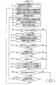
- FIG. 1 is a functional block diagram illustrating an embodiment.
- FIG. 2 is a diagram showing a table showing how the brake operation timing is changed
- FIG. 3 is a flowchart.
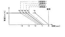
- FIG. 4 is a diagram (No. 1) showing a mode of changing the operation timing of the brake
- FIG. 5 is a diagram (part 2) illustrating a mode of changing the operation timing of the brake.
- the automatic brake control system 1 includes an automatic brake control device 2, a brain activity state detection unit 3, a mental state detection unit 4, a physical condition detection unit 5, a gaze direction detection unit 6, a conversation detection unit 7, It has a situation detection unit 8, a vehicle speed detection unit 9, and a brake device 10.
- the automatic brake control device 2 controls the output of the brake operation signal to the brake device 10 using the detection signals input from the detection units 3 to 9.
- the brain activity state detection unit 3 detects the activity state of the driver's brain using NIRS (Near Infra-Red Spectroscopy) technology.
- NIRS Near Infra-Red Spectroscopy
- the brain it is considered that two systems, an information transmission system responsible for neural activity, and an energy supply system supporting neural activity are closely related.
- nerve activity occurs, the blood vessels around it expand, and a regulating mechanism that supplies a lot of arterial blood including oxygen and glucose as energy sources works.
- the tissue near the active nerve it is assumed that the blood flow volume and the blood volume increase, and the oxidation state of blood (that is, the ratio between the oxyhemoglobin concentration and the deoxyhemoglobin concentration) changes.
- This relationship between neural activity and cerebral blood response is called neurovascular coupling, and the NIRS technique detects the concentration of local hemoglobin in the brain based on the assumption that neurovascular coupling exists. Detects driver brain activity status.
- the brain activity state detection unit 3 irradiates the driver's scalp with near infrared light, and receives light that is irregularly reflected by the irradiated near infrared light.
- the light component of the near-infrared light diffuses into the brain tissue due to the high biological permeability that penetrates the skin and bones, and about 20 ⁇ from the scalp. It reaches the cerebral cortex at a depth of 30 mm. Then, due to the property that the light absorption characteristics differ between the oxyhemoglobin concentration and the deoxyhemoglobin concentration in the blood, the light component irregularly reflected at a location several cm away from the irradiation point is detected.
- the brain activity state detection unit 3 detects the light component in this manner, thereby estimating the change between the oxyhemoglobin concentration and the deoxyhemoglobin concentration in the cerebral cortex, and detects the activity state of the driver's brain. In addition to the oxyhemoglobin concentration and deoxyhemoglobin concentration in the cerebral cortex, the brain activity state detection unit 3 also estimates the change in total hemoglobin concentration, which is the sum of both, and detects the driver's brain activity state. good. When detecting the activity state of the driver's brain, the brain activity state detection unit 3 outputs a detection signal indicating the detection result to the automatic brake control device 2.
- the mental state detection unit 4 detects whether or not the driver's mental state is, for example, a depressed state, and outputs a detection signal indicating the detection result to the automatic brake control device 2.
- the physical condition detection unit 5 detects the physical condition of the driver based on the driver's body temperature, heart rate, pulse rate, and the like, and outputs a detection signal indicating the detection result to the automatic brake control device 2.
- the line-of-sight direction detection unit 6 includes a driver photographing camera that photographs the upper body of the driver while the driver is sitting in the driver's seat.
- the line-of-sight direction detection unit 6 detects the driver's line-of-sight direction by analyzing the movement of the driver's head and eyeballs from the video captured by the driver photographing camera, and outputs a detection signal indicating the detection result to the automatic brake control device 2. Output to.
- the driver photographing camera is a CCD (Charge-Coupled Device) image sensor, a CMOS (Complementary-Metal-Oxide Semiconductor) image sensor, or the like, and may be singular or plural.
- the in-conversation detection unit 7 is configured to include a speaker that collects voices uttered by passengers including the driver.
- the in-conversation detection unit 7 analyzes the collected sound to detect whether or not the driver is in conversation with the passenger, and outputs a detection signal indicating the detection result to the automatic brake control device 2.
- the surrounding situation detection unit 8 is configured to include a vehicle surrounding photographing camera for photographing the periphery of the vehicle, a radar (LADAR: Laser Detection and Ranging), a rider (LIDAR: Light Detection and Ranging), and the like. These vehicle periphery photographing cameras, radars, and riders are disposed, for example, at the front portion of the vehicle body, the rear portion of the vehicle body, the right side portion of the vehicle body, and the left side portion of the vehicle body.
- the surrounding situation detection unit 8 detects a situation around the vehicle by analyzing a video taken by the vehicle surrounding photographing camera and a sensor signal from a radar or a rider, and outputs a detection signal indicating the detection result to the automatic brake control device 2. To do.
- the surrounding situation detection unit 8 detects the distance from the vehicle to the obstacle and the current safe speed as the situation around the vehicle.
- the surrounding state detection unit 8 may detect the state around the vehicle based on various types of traffic information such as the distance to the intersection and the road type in cooperation with the navigation system.
- the vehicle speed detection unit 9 includes, for example, a vehicle speed sensor.
- the vehicle speed detection unit 9 detects the vehicle speed and outputs a detection signal indicating the detection result to the automatic brake control device 2.
- the brake device 10 receives a brake operation signal from the automatic brake control device 2, the brake device 10 performs a brake operation.
- the automatic brake control device 2 includes a control unit 11 and a storage unit 12.
- the control unit 11 includes a microcomputer having a CPU (Central Processing Unit), a ROM (Read Only Memory), a RAM (Random Access Memory), and an I / O (Input / Output).
- the control unit 11 executes processing corresponding to the computer program by executing the computer program stored in the non-transitional tangible recording medium, and controls the overall operation of the automatic brake control device 2.
- the control unit 11 includes a brain activity state acquisition unit 11a, a mental state acquisition unit 11b, a physical condition acquisition unit 11c, a determination criterion setting unit 11d, a change determination unit 11e, a gaze direction determination unit 11f, and a determination unit during conversation 11g and a change control unit 11h.
- Each of these units 11a to 11h is configured by a computer program executed by the control unit 11, and is realized by software.
- the brain activity state acquisition unit 11a acquires the activity state of the driver's brain based on the detection signal input from the brain activity state detection unit 3.
- the mental state acquisition unit 11 b acquires the driver's mental state based on the detection signal input from the mental state detection unit 4.
- the physical condition acquisition unit 11 c acquires the physical condition of the driver based on the detection signal input from the physical condition detection unit 5.
- the determination criterion setting unit 11d uses a determination criterion for determining the driver's brain activity state based on the driver's mental state acquired by the mental state acquisition unit 11b and the driver's physical condition acquired by the physical condition acquisition unit 11c. Set.
- the change determination unit 11e needs to change the brake operation timing by comparing the degree of comfort and discomfort and the degree of tension as the driver's brain activity state acquired by the brain activity state acquisition unit 11a with the above-described determination criteria. Determine presence or absence.
- the line-of-sight direction determination unit 11 f determines the line-of-sight direction of the driver based on the detection signal input from the line-of-sight direction detection unit 6. Whether or not the driver is in conversation is determined based on the detection signal input from the during-conversation determination unit 11g and the during-conversation detection unit 7.
- the change control unit 11h changes the brake operation timing when the change determination unit 11e determines that the brake operation timing needs to be changed.
- the storage unit 12 stores the operation timing of the brake, the mental state of the driver, and the physical condition, and also stores a table indicating how the operation timing of the brake is changed as shown in FIG.
- the table is divided into four items, which do not change the operation timing of the brake, which is one step earlier, one step later, and two steps earlier, depending on the combination of the degree of comfort and discomfort.
- the control unit 11 performs an automatic brake control process.
- the control unit 11 starts the automatic brake control process when a start condition for the automatic brake control process is established, for example, the ignition switch is switched from OFF to ON.
- a start condition for the automatic brake control process for example, the ignition switch is switched from OFF to ON.
- the control unit 11 may use, for example, the automatic brake control processing start condition that the vehicle speed is equal to or higher than a certain speed or that the driver has performed a predetermined operation.
- the control unit 11 When the control unit 11 starts the automatic brake control process, the control unit 11 obtains the final brake operation timing at the previous operation stored in the storage unit 12 (S1).
- the control unit 11 uses the detection signal input from the mental state detection unit 4 to acquire the driver's mental state by the mental state acquisition unit 11b and uses the detection signal input from the physical condition detection unit 5 to determine the physical condition of the driver. Is acquired by the physical condition acquisition unit 11c (S2), and the acquired mental state and physical condition of the driver are stored in the storage unit 12 (S3).
- the control unit 11 uses the stored mental state and physical condition of the driver to set a determination criterion for determining the driver's brain activity state by the determination criterion setting unit 11d (S4).
- the control unit 11 acquires the distance from the vehicle to the obstacle and the current safe speed using the detection signal input from the surrounding state detection unit 8 (S5, S6), and uses the detection signal input from the vehicle speed detection unit 9.
- the current vehicle speed is acquired (S7).
- the control unit 11 uses the change determination unit 11e to determine whether or not the brake operation is necessary using the distance from the vehicle to the obstacle, the current safe speed, and the current vehicle speed (S8).
- S8: NO the control unit 11 determines whether or not an end condition for the automatic brake control process is satisfied (S9).
- control unit 11 determines that a brake operation is necessary for the purpose of avoiding a collision with an obstacle such as a preceding vehicle or a pedestrian or shifting to a safe speed (S8: YES)
- the control unit 11 outputs a brake operation signal. It outputs to the brake device 10 and operates the brake device 10 (S10).
- the control unit 11 uses the detection signal input from the brain activity state detection unit 3 to acquire the degree of comfort and discomfort and the degree of tension as the driver's brain activity state. (S11, S12, corresponding to the brain activity state acquisition procedure).
- the control unit 11 determines whether or not it is necessary to change the operation timing of the brake using the degree of comfort and discomfort and the degree of tension (S13, corresponding to a change determination procedure). In other words, the control unit 11 uses the table stored in the storage unit 12 and does not change the operation timing of the brake. Select.
- the control unit 11 determines that the degree of comfortable discomfort is comfortable and the degree of tension is low, it determines that there is no need to change the operation timing of the brake. That is, the control unit 11 determines that the brake operation is performed at the operation timing preferred by the driver if the degree of comfortable discomfort is comfortable and the degree of tension is low, and there is no need to change the operation timing of the brake. judge. If the control unit 11 determines that it is not necessary to change the brake operation timing (S13: NO), in this case as well, it is determined whether or not the termination condition for the automatic brake control process is satisfied (S9).
- the control unit 11 determines that the degree of comfort and discomfort is comfortable but the degree of tension is high, it determines that the brake operation timing needs to be advanced by one step. That is, if the degree of comfort and discomfort is comfortable but the degree of tension is high, the control unit 11 determines that the current brake operation timing is slightly late, and the brake operation timing needs to be advanced by one step. judge. If the controller 11 determines that the degree of comfort and discomfort is uncomfortable and the degree of tension is low, the controller 11 determines that the brake operation timing needs to be delayed by one step. That is, if the degree of comfort discomfort is unpleasant and the degree of tension is low, the control unit 11 determines that the current brake operation timing is slightly earlier, and the brake operation timing needs to be delayed by one step. judge.
- the controller 11 determines that the degree of comfort and discomfort is unpleasant and the degree of tension is high, the controller 11 determines that the brake operation timing needs to be advanced by two stages. That is, if the degree of comfort and discomfort is unpleasant and the degree of tension is high, the control unit 11 determines that the current brake operation timing is considerably late and determines that the brake operation timing needs to be advanced by two stages. To do.
- the control unit 11 uses the detection signal input from the gaze direction detection unit 6 to determine whether the driver's gaze direction is the traveling direction of the vehicle. Determination is performed by the determination unit 11f (S14). When determining that the driver's line-of-sight direction is not the vehicle traveling direction (S14: NO), the control unit 11 also determines whether or not the termination condition for the automatic brake control process is satisfied (S9). That is, when the driver's line-of-sight direction is not the traveling direction of the vehicle, the driver does not recognize how the brake operation has been performed, and there is a high possibility that the result of the brake operation is not reflected in the brain activity state. Therefore, the control unit 11 does not change the operation timing of the brake thereafter.
- the control unit 11 uses the detection signal input from the during-conversation detection unit 7 to determine whether the driver is in conversation. Determine (S15). If it determines with the driver
- the brake operation timing is advanced by one step selected by the table earlier by one step, delayed by one step, and advanced by two steps. (S16, corresponding to the change control procedure).
- the control unit 11 changes the brake operation timing in this manner, the control unit 11 stores the changed brake operation timing in the storage unit 12 (S17), and determines whether or not the condition for terminating the automatic brake control process is satisfied. (S9).
- the control part 11 will determine whether it is the update timing of the determination reference of the predetermined period set, for example beforehand (S18). ). If it determines with it not being the update timing of a determination standard (S18: NO), the control part 11 will return to step S5 and will repeat step S5 and subsequent steps. If the control unit 11 determines that it is the update timing of the determination criterion (S18: YES), the control unit 11 returns to step S2 and repeats step S2 and subsequent steps. On the other hand, when the control unit 11 determines that an end condition of the automatic brake control process such as the ignition switch switching from on to off is satisfied (S9: YES), the automatic brake control process ends.
- the control unit 11 changes the operation timing of the brake as follows by performing the series of processes described above.
- the situation in which automatic brake control is performed includes the case of performing a collision avoidance with an obstacle such as a preceding vehicle or a pedestrian, and the case of performing a transition to a safe speed. Each case will be described below.
- the control unit 11 determines that the brake device 10 may collide with an obstacle while the vehicle speed remains constant (that is, the course).
- the vehicle is stopped by operating the vehicle, but normally, the brake device 10 is not operated at “tx” shown in FIG. 4 which is the limit operation timing at which the vehicle stops immediately before the obstacle, and a default is given with a margin.
- the brake device 10 is operated at “ta” shown in FIG.
- the controller 11 determines that the degree of comfort and discomfort is comfortable and the degree of tension is low as the activity state of the driver's brain after operating the brake device 10, there is no need to change the operation timing of the brake.
- the brake operation timing is continued at the default operation timing.
- the control unit 11 determines that the degree of comfortable discomfort is comfortable but the degree of tension is high, the control unit 11 determines that the brake operation timing needs to be advanced by one step, and FIG. 4 shows the brake operation timing. It changes from “ta” to “tb” so that the degree of tension decreases at the next brake operation timing. Further, when the control unit 11 determines that the degree of comfort discomfort is uncomfortable and the degree of tension is low, the control unit 11 determines that the brake operation timing needs to be delayed by one step, and from “ta” illustrated in FIG. tc ", and the degree of comfort and discomfort becomes comfortable at the next brake operation timing.
- control unit 11 determines that the degree of comfortable discomfort is uncomfortable and the degree of tension is high, the control unit 11 determines that the brake operation timing needs to be advanced two stages, and from “ta” illustrated in FIG. "td", and the degree of tension decreases and the degree of comfort and discomfort becomes comfortable at the next brake operation timing.
- the control unit 11 performs automatic brake control 1.33 seconds earlier than the limit operation timing, and sets the acceleration of deceleration to 90 m / s ⁇ 2 (s squared) which is the limit acceleration. It is assumed that the acceleration is -77 ⁇ 10 ⁇ 6 (10 6) m / s ⁇ 2.
- the control unit 11 performs automatic brake control 0.9 seconds earlier than the limit operation timing at the operation timing one stage later, and the acceleration obtained by making the deceleration acceleration slower than the limit acceleration of 90 m / s ⁇ 2. It is assumed that ⁇ 83 ⁇ 10 ⁇ 6 m / s ⁇ 2.
- the control unit 11 performs automatic brake control 1.75 seconds earlier than the limit operation timing at the operation timing one step earlier, and makes the acceleration of deceleration slower than the limit acceleration of 90 m / s ⁇ 2. It is assumed that ⁇ 72 ⁇ 10 ⁇ 6 m / s ⁇ 2.
- the control unit 11 performs automatic brake control 2.17 seconds earlier than the limit operation timing at the operation timing that is two steps earlier, and makes the acceleration of deceleration slower than the limit acceleration of 90 m / s ⁇ 2. -67.5 ⁇ 10 ⁇ 6 m / s ⁇ 2.
- the control unit 11 determines that the degree of comfortable discomfort is comfortable and the degree of tension is low as the activity state of the driver's brain after operating the brake device 10.
- the brake operation timing is continued at “ta” shown in FIG. 5 which is the default operation timing.
- the control unit 11 determines that the degree of comfortable discomfort is comfortable but the degree of tension is high, the control unit 11 determines that the brake operation timing needs to be advanced by one step, and FIG. 5 shows the brake operation timing. It changes from “ta” to “tb” so that the degree of tension decreases at the next brake operation timing. Further, when the control unit 11 determines that the degree of comfort discomfort is uncomfortable and the degree of tension is low, the control unit 11 determines that the brake operation timing needs to be delayed by one step, and “ta” shown in FIG. tc ", and the degree of comfort and discomfort becomes comfortable at the next brake operation timing.
- control unit 11 determines that the degree of comfort discomfort is uncomfortable and the degree of tension is high, the control unit 11 determines that the brake operation timing needs to be advanced by two stages, and from “ta” illustrated in FIG. "td", and the degree of tension decreases and the degree of comfort and discomfort becomes comfortable at the next brake operation timing.
- the control unit 11 performs automatic brake control with a caution speed of 38 km / h, a safe speed of 28 km / h, and a deceleration acceleration of ⁇ 30.3 ⁇ 10 ⁇ 6 m / s ⁇ 2.
- the control unit 11 performs automatic brake control with an attention speed of 40 km / h at an operation timing one step later, a safety speed of 30 km / h, and a deceleration acceleration of ⁇ 57.6 ⁇ 10 ⁇ 6 m / s ⁇ 2. .
- the control unit 11 performs automatic brake control at a speed of attention of 36 km / h at an operation timing one step earlier, a safety speed of 26 km / h, and a deceleration acceleration of ⁇ 20.6 ⁇ 10 ⁇ 6 m / s ⁇ 2. .
- the control unit 11 performs automatic brake control with an attention speed of 34 km / h at an operation timing two steps earlier, a safe speed of 24 km / h, and a deceleration acceleration of ⁇ 15.6 ⁇ 10 ⁇ 6 m / s ⁇ 2. .
- the following effects can be obtained.
- the operation is performed by operating the brake device 10.
- the action timing of the brake can be changed by utilizing the change in the activity state of the person's brain.
- the brake device 10 can be operated at the operation timing preferred by the driver, and driving comfort can be enhanced.
- the degree of comfort and discomfort and the degree of tension are acquired as the brain activity state, and each of them is compared with a determination criterion to determine whether it is necessary to change the operation timing of the brake. Changes in the driver's brain activity state can be determined using the degree of discomfort and the degree of tension as indices.
- the mental state and physical condition of the driver are acquired, and the determination standard is set according to the mental state and physical condition of the driver. Therefore, the driver's mental state and physical condition are taken into consideration. Changes in brain activity can be determined.
- the automatic brake control device 2 periodically updates the judgment criteria during the driving period, so that even if the driver's mental state and physical condition change during the driving period, the judgment criteria suitable for the change are set one by one. It is possible to appropriately determine the change in the activity state of the driver's brain.
- the brake device 10 for the purpose of avoiding collision with an obstacle and shifting to a safe speed, it is determined whether or not it is necessary to change the operation timing of the brake.
- the brake device 10 can be operated at the operation timing preferred by the driver.
- the automatic brake control device 2 even if it is determined that the brake operation timing needs to be changed, if it is determined that the driver's line-of-sight direction is not the traveling direction of the vehicle or the driver is talking, the brake operation Since the timing is not changed, it is possible to avoid changing the brake operation timing in a situation where there is a high possibility that the result of the brake operation is not reflected in the brain activity state, and the brake operation timing is changed. Reliability can be increased.
- the configuration in which the operation timing of the brake is not changed when the driver's line-of-sight direction is not in the traveling direction of the vehicle or the driver is in conversation is illustrated. It is not necessary to determine whether the driver's line-of-sight direction is the traveling direction of the vehicle or whether the driver is talking.
- the driver may be notified of the change of the brake operation timing by display or voice output.
Landscapes
- Engineering & Computer Science (AREA)
- Health & Medical Sciences (AREA)
- Physics & Mathematics (AREA)
- Life Sciences & Earth Sciences (AREA)
- Transportation (AREA)
- Mechanical Engineering (AREA)
- General Physics & Mathematics (AREA)
- General Health & Medical Sciences (AREA)
- Biomedical Technology (AREA)
- Heart & Thoracic Surgery (AREA)
- Medical Informatics (AREA)
- Veterinary Medicine (AREA)
- Biophysics (AREA)
- Pathology (AREA)
- Public Health (AREA)
- Animal Behavior & Ethology (AREA)
- Surgery (AREA)
- Molecular Biology (AREA)
- Neurology (AREA)
- Theoretical Computer Science (AREA)
- General Engineering & Computer Science (AREA)
- Automation & Control Theory (AREA)
- Mathematical Physics (AREA)
- Spectroscopy & Molecular Physics (AREA)
- Child & Adolescent Psychology (AREA)
- Educational Technology (AREA)
- Hospice & Palliative Care (AREA)
- Psychiatry (AREA)
- Psychology (AREA)
- Social Psychology (AREA)
- Developmental Disabilities (AREA)
- Optics & Photonics (AREA)
- Dermatology (AREA)
- Human Computer Interaction (AREA)
- Neurosurgery (AREA)
- Regulating Braking Force (AREA)
- Traffic Control Systems (AREA)
- Control Of Driving Devices And Active Controlling Of Vehicle (AREA)
- Measurement Of The Respiration, Hearing Ability, Form, And Blood Characteristics Of Living Organisms (AREA)
Priority Applications (1)
| Application Number | Priority Date | Filing Date | Title |
|---|---|---|---|
| US16/086,369 US10960859B2 (en) | 2016-03-29 | 2017-01-16 | Automatic brake control apparatus and computer-readable non-transitory storage medium |
Applications Claiming Priority (2)
| Application Number | Priority Date | Filing Date | Title |
|---|---|---|---|
| JP2016-065643 | 2016-03-29 | ||
| JP2016065643A JP6579014B2 (ja) | 2016-03-29 | 2016-03-29 | 自動ブレーキ制御装置及びコンピュータプログラム |
Publications (1)
| Publication Number | Publication Date |
|---|---|
| WO2017168955A1 true WO2017168955A1 (ja) | 2017-10-05 |
Family
ID=59962901
Family Applications (1)
| Application Number | Title | Priority Date | Filing Date |
|---|---|---|---|
| PCT/JP2017/001219 Ceased WO2017168955A1 (ja) | 2016-03-29 | 2017-01-16 | 自動ブレーキ制御装置及びコンピュータプログラム |
Country Status (3)
| Country | Link |
|---|---|
| US (1) | US10960859B2 (enExample) |
| JP (1) | JP6579014B2 (enExample) |
| WO (1) | WO2017168955A1 (enExample) |
Families Citing this family (11)
| Publication number | Priority date | Publication date | Assignee | Title |
|---|---|---|---|---|
| US11173919B2 (en) * | 2016-07-20 | 2021-11-16 | Toyota Motor Europe | Control device, system and method for determining a comfort level of a driver |
| JP6878785B2 (ja) * | 2016-07-29 | 2021-06-02 | 日産自動車株式会社 | 制動制御方法及び制動制御装置 |
| JP6702113B2 (ja) * | 2016-09-16 | 2020-05-27 | 日産自動車株式会社 | 運転支援方法及び運転支援装置 |
| US11214280B2 (en) * | 2017-01-26 | 2022-01-04 | Ford Global Technologies, Llc | Autonomous vehicle providing driver education |
| JP2019026165A (ja) * | 2017-08-02 | 2019-02-21 | ローベルト ボッシュ ゲゼルシャフト ミット ベシュレンクテル ハフツング | 制御装置、車体挙動制御システム、モータサイクル、及び、制御方法 |
| CN111655149B (zh) * | 2018-03-15 | 2024-08-23 | 松下知识产权经营株式会社 | 用于推断用户的心理状态的系统、记录介质以及方法 |
| JP7188073B2 (ja) * | 2018-12-27 | 2022-12-13 | 日産自動車株式会社 | 車両制御方法及び車両制御装置 |
| US11780445B2 (en) * | 2020-01-13 | 2023-10-10 | Ford Global Technologies, Llc | Vehicle computer command system with a brain machine interface |
| US11721234B2 (en) * | 2020-10-14 | 2023-08-08 | GM Global Technology Operations LLC | Methods and systems to autonomously train drivers |
| CN112356841B (zh) * | 2020-11-26 | 2021-12-24 | 中国人民解放军国防科技大学 | 一种基于脑机交互的车辆控制方法及装置 |
| CN113276810B (zh) * | 2021-06-18 | 2022-11-29 | 北京百度网讯科技有限公司 | 用于车辆的制动方法、装置和设备 |
Citations (3)
| Publication number | Priority date | Publication date | Assignee | Title |
|---|---|---|---|---|
| JP2008037201A (ja) * | 2006-08-03 | 2008-02-21 | Toyota Motor Corp | 運転支援装置 |
| JP2011238133A (ja) * | 2010-05-12 | 2011-11-24 | Toyota Motor Corp | 運転支援装置 |
| JP2011248535A (ja) * | 2010-05-25 | 2011-12-08 | Toyota Motor Corp | 運転者状態判定装置、及び運転者支援装置 |
Family Cites Families (9)
| Publication number | Priority date | Publication date | Assignee | Title |
|---|---|---|---|---|
| JP2008247118A (ja) * | 2007-03-29 | 2008-10-16 | Mazda Motor Corp | 車両用運転支援装置 |
| JP2009018625A (ja) * | 2007-07-10 | 2009-01-29 | Toyota Motor Corp | 走行制御装置 |
| JP2010038821A (ja) | 2008-08-07 | 2010-02-18 | Sharp Corp | 情報処理装置および情報処理方法 |
| JP4500369B2 (ja) * | 2008-09-19 | 2010-07-14 | パナソニック株式会社 | 注意散漫検出装置、注意散漫検出方法およびコンピュータプログラム |
| JP5565136B2 (ja) * | 2010-06-25 | 2014-08-06 | 日産自動車株式会社 | 運転操作支援装置及び運転操作支援方法 |
| US9751534B2 (en) * | 2013-03-15 | 2017-09-05 | Honda Motor Co., Ltd. | System and method for responding to driver state |
| JP6128026B2 (ja) | 2014-03-17 | 2017-05-17 | 株式会社デンソー | 自動ブレーキシステム |
| JP2016013753A (ja) * | 2014-07-01 | 2016-01-28 | トヨタ自動車株式会社 | 車両用情報報知装置 |
| JP2016020177A (ja) * | 2014-07-15 | 2016-02-04 | 株式会社デンソー | 運転制御装置 |
-
2016
- 2016-03-29 JP JP2016065643A patent/JP6579014B2/ja active Active
-
2017
- 2017-01-16 US US16/086,369 patent/US10960859B2/en active Active
- 2017-01-16 WO PCT/JP2017/001219 patent/WO2017168955A1/ja not_active Ceased
Patent Citations (3)
| Publication number | Priority date | Publication date | Assignee | Title |
|---|---|---|---|---|
| JP2008037201A (ja) * | 2006-08-03 | 2008-02-21 | Toyota Motor Corp | 運転支援装置 |
| JP2011238133A (ja) * | 2010-05-12 | 2011-11-24 | Toyota Motor Corp | 運転支援装置 |
| JP2011248535A (ja) * | 2010-05-25 | 2011-12-08 | Toyota Motor Corp | 運転者状態判定装置、及び運転者支援装置 |
Also Published As
| Publication number | Publication date |
|---|---|
| US20190100175A1 (en) | 2019-04-04 |
| JP6579014B2 (ja) | 2019-09-25 |
| US10960859B2 (en) | 2021-03-30 |
| JP2017177933A (ja) | 2017-10-05 |
Similar Documents
| Publication | Publication Date | Title |
|---|---|---|
| JP6579014B2 (ja) | 自動ブレーキ制御装置及びコンピュータプログラム | |
| US12195050B2 (en) | Driver eyeball behavior information processing apparatus, processing system, processing method, and processing program | |
| US20190337521A1 (en) | Method and control unit for operating a self-driving car | |
| US10173667B2 (en) | Occupant based vehicle control | |
| US20190344790A1 (en) | Travel support device | |
| JP6213282B2 (ja) | 運転支援装置 | |
| US20190016344A1 (en) | Method for adjusting at least one operating parameter of a transportation vehicle, system for adjusting at least one operating parameter of a transportation vehicle, and transportation vehicle | |
| CN110254373A (zh) | 清醒度保持装置 | |
| US11430231B2 (en) | Emotion estimation device and emotion estimation method | |
| CN110871809A (zh) | 控制机动车辆中的车辆系统的方法 | |
| US20220169284A1 (en) | Vehicle control device | |
| CN107428342A (zh) | 用于运行机动车的方法和对应的机动车 | |
| JP6756174B2 (ja) | 車両制御装置 | |
| US20230278565A1 (en) | Driving assistance device | |
| JP2021066275A (ja) | 車両制御装置 | |
| US20220258771A1 (en) | Method to detect driver readiness for vehicle takeover requests | |
| JP2008204107A (ja) | 不注意警告装置、不注意警告装置の車両機器制御方法及び車両制御装置のプログラム | |
| JP2019008777A (ja) | 運転支援装置、記録装置、運転支援システム、運転支援方法およびプログラム | |
| US20200269857A1 (en) | Control system of vehicle, control method of the same, and non-transitory computer-readable storage medium | |
| JP2017049636A (ja) | 運転者状態検出装置 | |
| JP2019127238A (ja) | 車両の制御装置 | |
| JP7046748B2 (ja) | 運転者状態判定装置および運転者状態判定方法 | |
| JP2019020786A (ja) | 運転支援方法及び運転支援装置 | |
| JP2020097396A (ja) | 車両のルート及び/又は運転スタイルを室内状況に従って変更するための方法及び装置 | |
| WO2018211966A1 (ja) | 運転者監視装置、運転者監視方法及び運転者監視のためのプログラム |
Legal Events
| Date | Code | Title | Description |
|---|---|---|---|
| NENP | Non-entry into the national phase |
Ref country code: DE |
|
| 121 | Ep: the epo has been informed by wipo that ep was designated in this application |
Ref document number: 17773505 Country of ref document: EP Kind code of ref document: A1 |
|
| 122 | Ep: pct application non-entry in european phase |
Ref document number: 17773505 Country of ref document: EP Kind code of ref document: A1 |