WO2017168822A1 - 建設機械 - Google Patents
建設機械 Download PDFInfo
- Publication number
- WO2017168822A1 WO2017168822A1 PCT/JP2016/084103 JP2016084103W WO2017168822A1 WO 2017168822 A1 WO2017168822 A1 WO 2017168822A1 JP 2016084103 W JP2016084103 W JP 2016084103W WO 2017168822 A1 WO2017168822 A1 WO 2017168822A1
- Authority
- WO
- WIPO (PCT)
- Prior art keywords
- boom
- control valve
- pressure
- arm
- direction control
- Prior art date
- Legal status (The legal status is an assumption and is not a legal conclusion. Google has not performed a legal analysis and makes no representation as to the accuracy of the status listed.)
- Ceased
Links
Images


Classifications
-
- E—FIXED CONSTRUCTIONS
- E02—HYDRAULIC ENGINEERING; FOUNDATIONS; SOIL SHIFTING
- E02F—DREDGING; SOIL-SHIFTING
- E02F9/00—Component parts of dredgers or soil-shifting machines, not restricted to one of the kinds covered by groups E02F3/00 - E02F7/00
- E02F9/20—Drives; Control devices
- E02F9/22—Hydraulic or pneumatic drives
- E02F9/2221—Control of flow rate; Load sensing arrangements
-
- E—FIXED CONSTRUCTIONS
- E02—HYDRAULIC ENGINEERING; FOUNDATIONS; SOIL SHIFTING
- E02F—DREDGING; SOIL-SHIFTING
- E02F9/00—Component parts of dredgers or soil-shifting machines, not restricted to one of the kinds covered by groups E02F3/00 - E02F7/00
- E02F9/20—Drives; Control devices
- E02F9/22—Hydraulic or pneumatic drives
- E02F9/2278—Hydraulic circuits
- E02F9/2292—Systems with two or more pumps
-
- E—FIXED CONSTRUCTIONS
- E02—HYDRAULIC ENGINEERING; FOUNDATIONS; SOIL SHIFTING
- E02F—DREDGING; SOIL-SHIFTING
- E02F3/00—Dredgers; Soil-shifting machines
- E02F3/04—Dredgers; Soil-shifting machines mechanically-driven
- E02F3/28—Dredgers; Soil-shifting machines mechanically-driven with digging tools mounted on a dipper- or bucket-arm, i.e. there is either one arm or a pair of arms, e.g. dippers, buckets
- E02F3/36—Component parts
- E02F3/42—Drives for dippers, buckets, dipper-arms or bucket-arms
- E02F3/43—Control of dipper or bucket position; Control of sequence of drive operations
-
- E—FIXED CONSTRUCTIONS
- E02—HYDRAULIC ENGINEERING; FOUNDATIONS; SOIL SHIFTING
- E02F—DREDGING; SOIL-SHIFTING
- E02F9/00—Component parts of dredgers or soil-shifting machines, not restricted to one of the kinds covered by groups E02F3/00 - E02F7/00
- E02F9/20—Drives; Control devices
- E02F9/2025—Particular purposes of control systems not otherwise provided for
- E02F9/2029—Controlling the position of implements in function of its load, e.g. modifying the attitude of implements in accordance to vehicle speed
-
- E—FIXED CONSTRUCTIONS
- E02—HYDRAULIC ENGINEERING; FOUNDATIONS; SOIL SHIFTING
- E02F—DREDGING; SOIL-SHIFTING
- E02F9/00—Component parts of dredgers or soil-shifting machines, not restricted to one of the kinds covered by groups E02F3/00 - E02F7/00
- E02F9/20—Drives; Control devices
- E02F9/22—Hydraulic or pneumatic drives
- E02F9/2221—Control of flow rate; Load sensing arrangements
- E02F9/2239—Control of flow rate; Load sensing arrangements using two or more pumps with cross-assistance
- E02F9/2242—Control of flow rate; Load sensing arrangements using two or more pumps with cross-assistance including an electronic controller
-
- E—FIXED CONSTRUCTIONS
- E02—HYDRAULIC ENGINEERING; FOUNDATIONS; SOIL SHIFTING
- E02F—DREDGING; SOIL-SHIFTING
- E02F9/00—Component parts of dredgers or soil-shifting machines, not restricted to one of the kinds covered by groups E02F3/00 - E02F7/00
- E02F9/20—Drives; Control devices
- E02F9/22—Hydraulic or pneumatic drives
- E02F9/2264—Arrangements or adaptations of elements for hydraulic drives
- E02F9/2267—Valves or distributors
-
- F—MECHANICAL ENGINEERING; LIGHTING; HEATING; WEAPONS; BLASTING
- F15—FLUID-PRESSURE ACTUATORS; HYDRAULICS OR PNEUMATICS IN GENERAL
- F15B—SYSTEMS ACTING BY MEANS OF FLUIDS IN GENERAL; FLUID-PRESSURE ACTUATORS, e.g. SERVOMOTORS; DETAILS OF FLUID-PRESSURE SYSTEMS, NOT OTHERWISE PROVIDED FOR
- F15B11/00—Servomotor systems without provision for follow-up action; Circuits therefor
- F15B11/02—Systems essentially incorporating special features for controlling the speed or actuating force of an output member
- F15B11/028—Systems essentially incorporating special features for controlling the speed or actuating force of an output member for controlling the actuating force
-
- F—MECHANICAL ENGINEERING; LIGHTING; HEATING; WEAPONS; BLASTING
- F15—FLUID-PRESSURE ACTUATORS; HYDRAULICS OR PNEUMATICS IN GENERAL
- F15B—SYSTEMS ACTING BY MEANS OF FLUIDS IN GENERAL; FLUID-PRESSURE ACTUATORS, e.g. SERVOMOTORS; DETAILS OF FLUID-PRESSURE SYSTEMS, NOT OTHERWISE PROVIDED FOR
- F15B11/00—Servomotor systems without provision for follow-up action; Circuits therefor
- F15B11/02—Systems essentially incorporating special features for controlling the speed or actuating force of an output member
- F15B11/04—Systems essentially incorporating special features for controlling the speed or actuating force of an output member for controlling the speed
- F15B11/044—Systems essentially incorporating special features for controlling the speed or actuating force of an output member for controlling the speed by means in the return line, i.e. "meter out"
-
- F—MECHANICAL ENGINEERING; LIGHTING; HEATING; WEAPONS; BLASTING
- F15—FLUID-PRESSURE ACTUATORS; HYDRAULICS OR PNEUMATICS IN GENERAL
- F15B—SYSTEMS ACTING BY MEANS OF FLUIDS IN GENERAL; FLUID-PRESSURE ACTUATORS, e.g. SERVOMOTORS; DETAILS OF FLUID-PRESSURE SYSTEMS, NOT OTHERWISE PROVIDED FOR
- F15B11/00—Servomotor systems without provision for follow-up action; Circuits therefor
- F15B11/08—Servomotor systems without provision for follow-up action; Circuits therefor with only one servomotor
-
- F—MECHANICAL ENGINEERING; LIGHTING; HEATING; WEAPONS; BLASTING
- F15—FLUID-PRESSURE ACTUATORS; HYDRAULICS OR PNEUMATICS IN GENERAL
- F15B—SYSTEMS ACTING BY MEANS OF FLUIDS IN GENERAL; FLUID-PRESSURE ACTUATORS, e.g. SERVOMOTORS; DETAILS OF FLUID-PRESSURE SYSTEMS, NOT OTHERWISE PROVIDED FOR
- F15B11/00—Servomotor systems without provision for follow-up action; Circuits therefor
- F15B11/16—Servomotor systems without provision for follow-up action; Circuits therefor with two or more servomotors
- F15B11/17—Servomotor systems without provision for follow-up action; Circuits therefor with two or more servomotors using two or more pumps
Definitions
- the present invention relates to a construction machine.
- a construction machine has a hydraulic actuator such as a hydraulic cylinder that drives a mounted front working device, an operating device operated by an operator, a hydraulic pump, and an operation pilot pressure corresponding to an operation amount of the operating device.
- a directional control valve is driven to provide a control valve for controlling the flow rate and direction of pressure oil supplied from the hydraulic pump to the hydraulic actuator.
- control valve is equipped with a relief valve to prevent damage to the hydraulic equipment.
- a load pressure corresponding to an excavation reaction force (excavation load) is generated inside the hydraulic actuator that drives the front working device.
- the relief valve opens when the pressure in the hydraulic circuit does not exceed the pressure resistance of the hydraulic equipment due to the increase in load pressure, and releases the pressure oil to the tank. The energy of the pressure oil released from the relief valve is released as heat and is lost. Therefore, in a general control valve, directional control valves of different hydraulic actuators are arranged in parallel on the same pump line, and when the pressure in the hydraulic circuit rises, pressure oil is supplied to the actuator with a relatively low load pressure. By flowing (so-called diversion), the pressure rise in the hydraulic circuit is suppressed and loss due to the relief operation is avoided.
- a trajectory control device for a construction machine that always converges the front work device tip to a target trajectory through a good trajectory that matches a human feeling regardless of the amount of operation of the operator (for example, patents) Reference 1).
- the trajectory control device calculates the position and orientation of the front working device based on the signal from the angle detector, and calculates the target speed vector of the front working device based on the signal from the operation lever device.
- the target speed vector is corrected so as to be directed to a point that has advanced a predetermined distance forward from a point on the target locus that is the shortest distance from the front working device tip, and corresponds to the corrected target speed vector.
- a target pilot pressure for driving the hydraulic control valve is calculated.
- the proportional solenoid valve provided in the operation hydraulic circuit is controlled so as to generate the calculated target pilot pressure.
- control device for a hydraulic construction machine that is individually controlled (for example, see Patent Document 2).
- the control device includes first and second boom control valves that control the flow of pressure oil to the boom cylinder, and first and second arm control valves that control the flow of pressure oil to the arm cylinder.
- a proportional valve for generating a pilot signal is attached, and a control signal is obtained using a map set for each work mode according to the boom lever stroke and arm lever stroke signal, thereby controlling each proportional valve. .
- the trajectory control device for a construction machine described in Patent Document 1 controls an operation pilot pressure that drives and controls a control valve that constitutes a conventional construction machine, whereby a directional control valve arranged in parallel on the same pump line. Adjust the opening and converge the front work equipment tip to the target trajectory. For this reason, when the excavation load increases, there is a possibility that the flow rate changes and the front working device tip deviates from the target locus, and convergence to the target locus after deviating may be delayed.
- the front working device is driven by the boom cylinder and the arm cylinder to perform excavation (leveling work) by horizontal pulling
- the load pressure in the direction of extension of the boom cylinder Is higher than the load pressure in the extension direction of the arm cylinder, it is necessary to reduce the opening degree of the directional control valve for the arm and increase the opening degree of the directional control valve for the boom.
- the load pressure of the arm cylinder increases due to the reaction force from the excavation object, and as a result, the boom is lifted upward via the arm that receives the reaction force.
- the load pressure decreases, the load pressure of the arm cylinder becomes higher than the load pressure of the boom cylinder, and the partial flow rate to the boom cylinder increases.
- the speed of the arm cylinder decreases, and conversely, the speed of the boom cylinder increases, and the speed balance may be lost, and the front end of the front working device may deviate from the target locus.
- the above-described construction machine trajectory control device controls the operation pilot pressure in accordance with the deviation after the front working device tip deviates from the target trajectory due to a change in the partial flow rate, so that convergence to the target trajectory may be delayed. There was sex.
- the present invention has been made on the basis of the above-described matters, and its purpose is to perform water averaging and perform a predetermined amount while avoiding loss due to relief even if the excavation load increases in a work such as a slope shaping work. It is to provide a construction machine capable of obtaining finishing accuracy.
- the present application includes a plurality of means for solving the above-described problems.
- a first hydraulic actuator, a second hydraulic actuator, a work machine driven by the first hydraulic actuator and the second hydraulic actuator A first hydraulic pump, a second hydraulic pump, and a first pump line that is a discharge oil passage of the first hydraulic pump, and controls a flow rate and a direction of pressure oil supplied to the first hydraulic actuator.
- a first speed increasing direction control that is provided in a first direction control valve and a second pump line that is a discharge oil passage of the second hydraulic pump and controls a flow rate and a direction of pressure oil supplied to the first hydraulic actuator.
- a second direction control for controlling a flow rate and direction of pressure oil provided to the second hydraulic actuator and provided in a valve and a second pump line which is a discharge oil passage of the second hydraulic pump;
- a first excavation load sensor that detects an excavation load applied to the work implement;
- a first acceleration control unit that drives the first acceleration direction control valve, and the first acceleration control. The unit controls the drive amount of the first acceleration direction control valve according to the excavation load detected by the excavation load sensor.
- the drive amount of the first speed increasing direction control valve configured to be diverted with the second direction control valve is controlled according to the excavation load, loss due to relief is avoided even when the excavation load increases.
- the deviation from the target locus can be prevented by suppressing the diversion. As a result, a predetermined finishing accuracy can be ensured.
- 1 is a perspective view showing a hydraulic excavator provided with a first embodiment of a construction machine of the present invention.
- 1 is a configuration diagram illustrating a hydraulic drive device for a construction machine including a first embodiment of a construction machine according to the present invention. It is a conceptual diagram which shows the structure of the main controller which comprises 1st Embodiment of the construction machine of this invention. It is a control block diagram which shows an example of the calculation content of the main spool control part of the main controller which comprises 1st Embodiment of the construction machine of this invention. It is a control block diagram which shows an example of the calculation content of the boom acceleration control part of the main controller which comprises 1st Embodiment of the construction machine of this invention.
- FIG. 1 is a perspective view showing a hydraulic excavator provided with a first embodiment of a construction machine of the present invention.
- the excavator includes a lower traveling body 9, an upper swing body 10, and a work machine 15.
- the lower traveling body 9 has left and right crawler traveling devices and is driven by left and right traveling hydraulic motors 3b and 3a (only the left side 3b is shown).
- the upper swing body 10 is mounted on the lower traveling body 9 so as to be swingable and is driven to swing by the swing hydraulic motor 4.
- the upper swing body 10 includes an engine 14 as a prime mover and a hydraulic pump device 2 driven by the engine 14.
- the work machine 15 is attached to the front part of the upper swing body 10 so as to be able to be lifted.
- the upper swing body 10 is provided with a driver's cab.
- the right operating lever device 1a for traveling, the left operating lever device 1b for traveling, the right operating lever device 1c for instructing the operation and turning operation of the work implement 15 are provided.
- An operation device such as the left operation lever device 1d is disposed.
- the work machine 15 has an articulated structure including a boom 11, an arm 12, and a bucket 8, and the boom 11 is rotated up and down with respect to the upper swing body 10 by expansion and contraction of the boom cylinder 5.
- the bucket 8 pivots up and down and back and forth with respect to the boom 11 by expansion and contraction, and the bucket 8 rotates up and down and front and back with respect to the arm 12 by expansion and contraction of the bucket cylinder 7.
- an angle detector 13 a that is provided in the vicinity of the connecting portion between the upper swing body 10 and the boom 11 and detects the angle of the boom 11, and the connection between the boom 11 and the arm 12.
- an angle detector 13b for detecting the angle of the arm 12
- an angle detector 13c for detecting the angle of the bucket 8 provided in the vicinity of the arm 12 and the bucket 8.
- the angle signals detected by these angle detectors 13a to 13c are input to the main controller 100 described later.
- the control valve 20 is a flow of pressure oil (flow rate and direction) supplied from the hydraulic pump device 2 to each of the hydraulic actuators such as the boom cylinder 5, the arm cylinder 6, the bucket cylinder 7 and the left and right traveling hydraulic motors 3b and 3a. ).
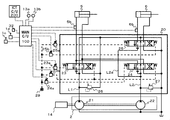
- FIG. 2 is a block diagram showing a hydraulic drive device for a construction machine provided with the first embodiment of the construction machine of the present invention.
- the description will be made assuming that only the boom cylinder 5 and the arm cylinder 6 are provided as hydraulic actuators, and illustration and description of a drain circuit and the like not directly related to the embodiment of the present invention are omitted. . Further, description of a load check valve and the like having the same configuration and operation as those of a conventional hydraulic drive device will be omitted.
- the hydraulic drive device includes a hydraulic pump device 2, a boom cylinder 5 as a first hydraulic actuator, an arm cylinder 6 as a second hydraulic actuator, a right operation lever device 1c, and a left operation lever device 1d.
- a control valve 20, a main controller 100, and an information controller 200 are provided.
- the hydraulic pump device 2 includes a first hydraulic pump 21 and a second hydraulic pump 22.
- the first hydraulic pump 21 and the second hydraulic pump 22 are driven by the engine 14 and discharge pressure oil to the first pump line L1 and the second pump line L2, respectively.
- the first hydraulic pump 21 and the second hydraulic pump 22 are described as fixed displacement hydraulic pumps, but the present invention is not limited to this, and a variable displacement hydraulic pump is used. It may be configured.
- the control valve 20 includes two pump lines including a first pump line L1 and a second pump line L2.
- a boom direction control valve 23 as a first direction control valve is connected to the first pump line L1, and the pressure oil discharged from the first hydraulic pump 21 is supplied to the boom cylinder 5.
- a boom speed increasing direction control valve 24 as a first speed increasing direction control valve and an arm direction control valve 25 as a second direction control valve are connected to the second pump line L2, and the second hydraulic pressure is controlled.
- the pressure oil discharged from the pump 22 is supplied to the boom cylinder 5 and the arm cylinder 6.
- the boom speed increasing direction control valve 24 and the arm direction control valve 25 are configured to be diverted by a parallel circuit L2a.
- Relief valves 26 and 27 are individually provided for the first pump line L1 and the second pump line L2. When the pressure of each pump line reaches a preset relief pressure, the respective relief valves 26 and 27 are opened to release the pressure oil to the tank.
- the boom direction control valve 23 is driven and operated by pilot pressure oil supplied to the pressure receiving part via the electromagnetic proportional valves 23a and 23b.
- the boom speed increasing direction control valve 24 is received by electromagnetic proportional valves 24a and 23b (shared with the boom direction control valve 23), and the arm direction control valve 25 is received by each valve via the electromagnetic proportional valves 25a and 25b.
- the pilot pressure oil is supplied to the part and operates.
- the right operation lever device 1c outputs a voltage signal corresponding to the operation amount and operation direction of the operation lever to the main controller 100 as a boom operation signal.
- the left operation lever device 1d outputs a voltage signal corresponding to the operation amount and operation direction of the operation lever to the main controller 100 as an arm operation signal.
- the boom cylinder 5 is provided with a boom cylinder bottom chamber side pressure sensor 5b for detecting the pressure of the bottom side oil chamber, and the arm cylinder 6 detects the pressure of the bottom side oil chamber.
- An arm cylinder bottom chamber side pressure sensor 6b is provided as a sensor. The boom cylinder bottom chamber side pressure sensor 5b and the arm cylinder bottom chamber side pressure sensor 6b output the detected pressure signals to the main controller 100, respectively.
- the mode setting switch 32 is arranged in the cab and allows the operator to select whether or not to enable semi-automatic control in the work of the construction machine. True: semi-automatic control is enabled or false : Enables selection of semi-automatic control disabled.
- the main controller 100 includes a semi-automatic control enable flag transmitted from the mode setting switch 32, target surface information transmitted from the information controller 200, boom angle signals, arm angle signals, boom cylinders transmitted from the angle detectors 13a and 13b, respectively.
- the boom bottom pressure signal and the arm bottom pressure signal respectively transmitted from the bottom chamber side pressure sensor 5b and the arm cylinder bottom chamber side pressure sensor 6b are input, and the electromagnetic proportional valves 23a, 23b, 24a, Command signals for driving 25a and 25b are output to each.
- the information controller 200 since the calculation performed by the information controller 200 is not directly related to the present invention, the description thereof is omitted.
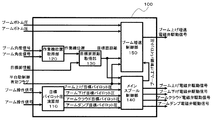
- FIG. 3 is a conceptual diagram showing the configuration of the main controller constituting the first embodiment of the construction machine of the present invention
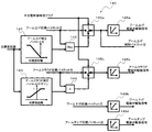
- FIG. 4 is the main spool of the main controller constituting the first embodiment of the construction machine of the present invention.
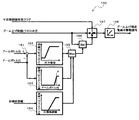
- FIG. 5 is a control block diagram showing an example of the calculation contents of the boom speed increasing control unit of the main controller constituting the first embodiment of the construction machine of the present invention. is there.
- the main controller 100 includes a target pilot pressure calculation unit 110, a work implement position acquisition unit 120, a target surface distance acquisition unit 130, a main spool control unit 140, and a boom acceleration control unit 150. It has.
- the target pilot pressure calculation unit 110 receives the boom operation amount signal from the right operation lever device 1c and the arm operation amount signal from the left operation lever device 1d, and the boom raising target pilot pressure and the boom according to the input signal.
- the lowering target pilot pressure, the arm cloud target pilot pressure, and the arm dump target pilot pressure are calculated and output to the main spool control unit 140.
- the boom raising target pilot pressure increases as the boom operation amount increases in the boom raising direction
- the boom lowering target pilot pressure increases as the boom operation amount increases in the boom lowering direction
- the arm cloud target pilot pressure increases as the arm operation amount increases in the arm cloud direction
- the arm dump target pilot pressure increases as the arm operation amount increases in the arm dump direction.
- the work machine position acquisition unit 120 receives the boom angle signal and the arm angle signal from the angle detectors 13a and 13b, and uses the geometric information of the boom 11 and the arm 12 that is set in advance according to the input signal to bucket. 8 is calculated and output to the target surface distance acquisition unit 130 as a work implement position signal.
- the work machine position is calculated as one point in a coordinate system fixed to the construction machine, for example.
- the work machine position is not limited to this, and may be calculated as a plurality of point groups in consideration of the shape of the work machine 15. Moreover, you may perform the calculation similar to the locus
- the target surface distance acquisition unit 130 inputs the target surface information transmitted from the information controller 200 and the work machine position signal from the work machine position acquisition unit 120, and the distance between the work machine 15 and the construction target surface (hereinafter referred to as “work machine surface”). Is calculated and output to the main spool control unit 140 and the boom speed increase control unit 150.
- the target plane information is given as, for example, two points in a two-dimensional plane coordinate system fixed to the construction machine.
- the target surface information is not limited to this, and may be given as three points constituting a plane in the global three-dimensional coordinate system. In this case, it is necessary to perform coordinate conversion to the same coordinate system as the work machine position.
- the target surface distance may be calculated using the point closest to the target surface information. Moreover, you may perform the calculation similar to the shortest distance (DELTA) h of the trajectory control apparatus of the construction machine described in patent document 1.
- DELTA shortest distance
- the main spool control unit 140 includes a semi-automatic control enable flag transmitted from the mode setting switch 32, a boom raising target pilot pressure from the target pilot pressure calculating unit 110, a boom lowering target pilot pressure, an arm cloud target pilot pressure, When the arm dump target pilot pressure and the target surface distance signal from the target surface distance acquisition unit 130 are input and the semi-automatic control valid flag is true, each target pilot pressure is corrected and calculated according to the target surface distance.
- the boom raising solenoid valve drive signal, the boom lower solenoid valve drive signal, the arm cloud solenoid valve drive signal, and the arm dump solenoid valve drive signal are calculated, and the electromagnetic proportional valves 23a, 23b, 25a, 25b corresponding to the respective signals are calculated.
- a drive signal for driving is output. Details of the calculation performed by the main spool control unit 140 will be described later.
- the boom acceleration control unit 150 includes a semi-automatic control enable flag transmitted from the mode setting switch 32, a boom raising control pilot pressure from the main spool control unit 140, a target surface distance signal from the target surface distance acquisition unit 130,
- the boom cylinder bottom side oil chamber pressure signal (hereinafter also referred to as a boom bottom pressure signal) and the arm cylinder bottom side oil chamber pressure signal (hereinafter also referred to as arm bottom pressure signals) respectively transmitted from the pressure sensors 5b and 6b are input. Then, the boom raising target pilot pressure is corrected and calculated, the boom raising acceleration electromagnetic valve driving signal is calculated, and the driving signal for driving the electromagnetic proportional valve 24a is output. Details of the calculation performed by the boom acceleration control unit 150 will be described later.
- the main spool control unit 140 includes a boom raising correction pilot pressure table 141, a maximum value selector 142, an arm cloud correction pilot pressure gain table 143, a multiplier 144, selectors 145a and 145c, and a solenoid valve drive signal table. 146a, 146b, 146c, and 146d.
- the boom raising correction pilot pressure table 141 inputs a target surface distance signal, calculates a boom raising correction pilot pressure using a preset table, and outputs it to the maximum value selector 142.
- the maximum value selector 142 receives the boom raising target pilot pressure and the boom raising correction pilot pressure, selects one of the maximum values, and outputs it to the second input terminal of the selector 145a.
- the boom raising correction pilot pressure table 141 is set so that the boom raising correction pilot pressure increases as the target surface distance increases in the negative direction, that is, as the work implement 15 enters the target surface deeper. Thereby, the boom raising operation is performed according to the target surface distance, and entry of the work machine 15 into the target surface can be restricted.
- the selector 145a inputs the boom raising target pilot pressure signal to the first input terminal, the output signal of the above-described maximum value selector 142 to the second input terminal, and the semi-automatic control valid flag signal to the switching input terminal. To do.
- the selector 145a selectively outputs the boom raising target pilot pressure signal when the semi-automatic control valid flag signal is false, and the boom raising target pilot pressure signal and the boom raising corrected pilot pressure signal when the semi-automatic control valid flag signal is true.
- Select and output the maximum value of either The output signal from the selector 145a is output to the solenoid valve drive signal table 146a and the boom speed increasing control unit 150 as a boom raising control pilot pressure signal.
- the solenoid valve drive signal table 146a calculates and outputs a solenoid valve drive signal using a preset table according to the input boom raising control pilot pressure signal, and drives the solenoid proportional valve 23a.
- the electromagnetic valve drive signal table 146b calculates and outputs an electromagnetic valve drive signal using a preset table in accordance with the input boom up / down target pilot pressure signal, and drives the electromagnetic proportional valve 23b.
- the arm cloud correction pilot pressure gain table 143 inputs a target surface distance signal, calculates an arm cloud correction pilot pressure gain using a table set in advance according to the target surface distance, and outputs the calculated value to the multiplier 144. .
- the multiplier 144 receives the arm cloud target pilot pressure and the arm cloud correction pilot pressure gain, multiplies the input values, and outputs the result to the second input terminal of the selector 145c.
- the arm cloud correction pilot pressure gain table 143 is set so that the arm cloud correction pilot pressure gain decreases as the target surface distance increases in the negative direction, that is, as the work implement 15 enters the target surface deeper. Thereby, arm cloud speed becomes small according to target surface distance, and the penetration
- the selector 145c inputs the arm cloud target pilot pressure signal to the first input terminal, the output signal of the multiplier 144 described above to the second input terminal, and the semi-automatic control valid flag signal to the switching input terminal.
- the selector 145c selectively outputs the arm cloud target pilot pressure signal when the semi-automatic control valid flag signal is false, and the arm cloud target pilot pressure signal and the arm cloud corrected pilot pressure gain when the semi-automatic control valid flag signal is true.
- the arm cloud correction pilot pressure signal multiplied by is selectively output.
- the output signal from the selector 145c is output to the electromagnetic valve drive signal table 146c as an arm cloud control pilot pressure signal.
- the electromagnetic valve drive signal table 146c calculates and outputs an electromagnetic valve drive signal using a preset table according to the input arm cloud control pilot pressure signal, and drives the electromagnetic proportional valve 25a.
- the solenoid valve drive signal table 146d calculates and outputs a solenoid valve drive signal using a preset table in accordance with the input arm dump target pilot pressure signal, and drives the solenoid proportional valve 25b.
- boom raising target pilot pressure and the arm cloud target pilot pressure may be corrected by the vector direction correction described in Patent Document 1.
- the boom acceleration control unit 150 includes a subtractor 151, a pilot pressure upper limit value table 152, a second pilot pressure upper limit value table 153, a third pilot pressure upper limit value table 154, a maximum value selector 155, and a minimum value.
- a selector 156, a selector 157, and a solenoid valve drive signal table 158 are provided.
- the subtracter 151 receives the boom bottom pressure signal and the arm bottom pressure signal, calculates the pressure deviation by subtracting the arm bottom pressure signal from the boom bottom pressure signal, and outputs the pressure deviation to the pilot pressure upper limit value table 152.
- a small pressure deviation indicates that the arm bottom pressure increases with respect to the boom bottom pressure, and this indicates that the excavation load applied to the work implement 15 has increased.
- the pilot pressure upper limit value table 152 calculates a pilot pressure upper limit value using a preset table according to the input pressure deviation, and outputs it to the maximum value selector 155.
- the pilot pressure upper limit value table 152 is set so that the pilot pressure upper limit value decreases as the pressure deviation between the boom bottom pressure signal and the arm bottom pressure signal decreases, that is, as the excavation load applied to the work implement 15 increases.
- the second pilot pressure upper limit value table 153 calculates the second pilot pressure upper limit value using a preset table according to the input arm bottom pressure signal, and outputs it to the maximum value selector 155.
- the second pilot pressure upper limit value table 153 is set so that the second pilot pressure upper limit value increases as the arm bottom pressure signal increases. It should be noted that the arm bottom pressure indicated by the dotted line A in the figure is substantially coincident with the relief pressure, and the second pilot pressure upper limit value is maximized until the arm bottom pressure substantially coincides with the relief pressure. By doing this, it is detected that the arm bottom pressure has increased and approached the relief pressure, the boom raising acceleration pilot pressure discharged by the electromagnetic proportional valve 24a is increased, and the meter-in opening of the boom acceleration direction control valve 24 is increased. Enlarge.
- the third pilot pressure upper limit value table 154 receives the target surface distance signal, calculates a third pilot pressure upper limit value using a preset table, and outputs it to the maximum value selector 155.
- the third pilot pressure upper limit value table 154 is set so that the second pilot pressure upper limit value increases as the target surface distance increases.
- the maximum value selector 155 inputs the pilot pressure upper limit value, the second pilot pressure upper limit value, and the third pilot pressure upper limit value, selects any one of the maximum values, corrects the pilot pressure upper limit value, and sets the minimum value.
- the data is output to the selector 156.
- the minimum value selector 156 inputs the boom raising control pilot pressure generated by the operator's lever operation and the pilot pressure upper limit value from the maximum value selector 155, and selects any one of the minimum values to thereby control the boom raising control pilot.
- the pressure is corrected and output to the second input terminal of the selector 157.
- the selector 157 inputs the boom raising control pilot pressure signal to the first input terminal, the output signal of the above-described minimum value selector 156 to the second input terminal, and the semi-automatic control valid flag signal to the switching input terminal. To do.
- the selector 157 selectively outputs the boom raising control pilot pressure signal when the semi-automatic control valid flag signal is false, and when the semi-automatic control valid flag signal is true, the boom raising control pilot pressure is selected as the boom bottom pressure and arm bottom pressure.
- the value corrected according to the target surface distance is selected and output.
- the output signal from the selector 157 is output to the solenoid valve drive signal table 158.
- the electromagnetic valve driving signal table 158 calculates and outputs a boom raising acceleration electromagnetic valve driving signal using a preset table according to the boom raising control pilot pressure, and drives the electromagnetic proportional valve 24a.
- FIG. 6 is a flowchart showing an example of a calculation flow of the boom speed increasing control unit of the main controller constituting the first embodiment of the construction machine of the present invention.
- the boom acceleration control unit 150 of the main controller 100 determines whether or not semi-automatic control is valid (step S101). Specifically, it is determined whether the semi-automatic control valid flag signal is true or false. If the semi-automatic control valid flag signal is true (step S102), the process proceeds. If not, the process proceeds to return.
- the boom acceleration control unit 150 calculates the pilot pressure upper limit value, the second pilot pressure upper limit value, and the third pilot pressure upper limit value (steps S102, S103, S104). Specifically, it is executed by the above-described pilot pressure upper limit value table 152, second pilot pressure upper limit value table 153, and third pilot pressure upper limit value table 154.
- the boom acceleration control unit 150 determines whether or not the pilot pressure upper limit value exceeds the second pilot pressure upper limit value (step S105). If the pilot pressure upper limit exceeds the second pilot pressure upper limit (step S107), the process proceeds to step S107. Otherwise, the process proceeds to (step S106).
- step S105 when the pilot pressure upper limit value is not exceeding the second pilot pressure upper limit value, the boom acceleration control unit 150 sets the pilot pressure upper limit value to the second pilot pressure upper limit value (step S106). Thereafter, the process proceeds to (Step S107).
- the boom acceleration control unit 150 determines whether or not the pilot pressure upper limit value exceeds the third pilot pressure upper limit value (step S107). If the pilot pressure upper limit exceeds the third pilot pressure upper limit (step S109), the process proceeds to step S109. Otherwise, the process proceeds to (step S108).
- step S107 if the pilot pressure upper limit value is not exceeding the third pilot pressure upper limit value, the boom acceleration control unit 150 sets the pilot pressure upper limit value to the third pilot pressure upper limit value (step S108). Thereafter, the process proceeds to (Step S109).
- the boom acceleration control unit 150 determines whether or not the boom control pilot pressure is less than the pilot pressure upper limit value (step S109). When the boom control pilot pressure is less than the pilot pressure upper limit value, the process proceeds to return, and the boom raising acceleration solenoid valve 24a is controlled according to the boom raising control pilot pressure. In this case, the control of the drive amount of the boom speed increasing direction control valve 24 by the excavation load or the like, which is a feature of the present invention, is not executed. When the boom control pilot pressure is not less than the pilot pressure upper limit value, the process proceeds to (Step S110).
- step S109 when the boom control pilot pressure is not less than the pilot pressure upper limit value, the boom acceleration control unit 150 sets the boom raising control pilot pressure to the pilot pressure upper limit value (step S110). Specifically, the boom raising acceleration electromagnetic valve 24a is controlled according to the pilot pressure upper limit value. As a result, the driving amount of the boom speed increasing direction control valve 24 is controlled by the excavation load or the like, so that even if the excavation load increases, the loss due to the relief is avoided and the diversion is suppressed and the deviation from the target locus is avoided. Can be prevented.
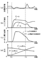
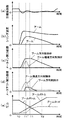
- FIG. 7A is a characteristic diagram showing an example of time-series operation of a conventional construction machine
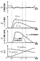
- FIG. 7B is a characteristic diagram showing an example of time-series operation of the construction machine in one embodiment of the construction machine of the present invention.
- FIG. 7A shows an example in which the boom direction control valve 23 and the boom acceleration direction control valve 24 are driven with the same pilot pressure
- FIG. 7B shows the boom direction control valve 23 and the boom acceleration direction control valve 24 individually. An example of driving with pilot pressure is shown.
- the horizontal axis indicates time
- the vertical axis indicates (a) target surface distance, (b) cylinder speed, (c) meter-in opening area, (d) arm bottom pressure and cylinder bottom pressure.
- the target surface distance refers to the distance between the work machine 15 and the construction target surface.
- Time T1 indicates the time when the pressure of the arm bottom pressure of the arm cylinder 6 becomes higher than the boom bottom pressure of the boom cylinder 5.
- FIG. 7B also operates in the same manner as in FIG. 7A until time T1 '.
- the meter-in opening area of the boom speed increasing direction control valve 24 decreases as shown in FIG.
- the flow rate that passes through the acceleration direction control valve 24 does not increase.
- the balance between the boom cylinder speed and the arm cylinder speed is maintained as shown in FIG.
- the drive amount of the first speed increasing direction control valve configured to be divertable with the second direction control valve is controlled according to the excavation load, Even if the excavation load increases, loss due to relief can be avoided and the diversion can be suppressed to prevent deviation from the target locus. As a result, a predetermined finishing accuracy can be ensured.
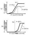
- FIG. 8A is an opening characteristic diagram showing an example of an opening characteristic of a boom direction control valve and a boom speed increasing direction control valve in a conventional construction machine
- FIG. 8B is a boom direction constituting a second embodiment of the construction machine of the present invention. It is an opening characteristic figure which shows an example of the opening characteristic of a control valve and a boom acceleration direction control valve.
- the configuration of the hydraulic drive device is substantially the same as that of the first embodiment, but the opening area characteristic with respect to the pilot pressure is changed from the characteristic of the general prior art. Different points.
- FIG. 8A shows the opening area on the boom raising side of the boom direction control valve 23 with respect to the boom raising pilot pressure in the conventional construction machine
- FIG. 8A shows the boom raising acceleration pilot pressure in the conventional construction machine.
- the opening area on the boom raising side of the boom speed increasing direction control valve 24 is shown.
- FIG. 8B shows the opening area on the boom raising side of the boom direction control valve 23 with respect to the boom raising pilot pressure in the second embodiment of the present invention
- the opening area on the boom raising side of the boom acceleration direction control valve 24 with respect to the boom raising acceleration pilot pressure in the second embodiment is shown.
- the solid line indicates the meter-in opening area characteristic
- the broken line indicates the meter-out opening area characteristic.
- the opening area of the meter-in and the opening area of the meter-out are simultaneously opened with respect to each boom raising pilot pressure. Generally it is set.
- the boom direction control valve 23 has a meter-in opening area larger than a meter-out opening area with respect to the boom raising pilot pressure.
- the boom acceleration direction control valve 24 is set so as to start increasing, and the opening area of the meter-out with respect to the boom raising acceleration pilot pressure is larger than the opening area of the meter-in as shown in FIG. Is also set to start increasing first.
- the meter out of the boom acceleration direction control valve 24 is compared.
- the pilot pressure at the beginning of opening of the boom speed increasing direction control valve 24 is set to a value lower than the pilot pressure at the beginning of opening of the boom direction control valve 23.
- the opening area of the boom meter-out can be adjusted only by the boom speed increasing direction control valve 24 in the region where the pilot pressure is low, that is, the region where the boom speed is low.
- the boom raising pilot pressure is given as the broken line Pi1 shown in FIG. 8B (a)
- the boom raising acceleration pilot pressure is given as the broken line Pi2 shown in FIG. 8B (b).
- the total meter-out opening area is The embodiment is smaller than the prior art.
- the meter-in opening area of the boom acceleration direction control valve 24 is closed and the meter-out opening area is reduced simultaneously. Therefore, the boom rod pressure can be increased. As a result, a decrease in load pressure in the extending direction of the boom cylinder 5 due to the excavation reaction force can be prevented, so that the speed balance between the arm cylinder 6 and the boom cylinder 5 is maintained. As a result, a predetermined finishing accuracy can be obtained.
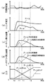
- FIG. 9A is a characteristic diagram showing an example of time-series operation of a construction machine to which a directional control valve having an opening area characteristic of the prior art is applied in the second embodiment of the construction machine of the present invention
- FIG. It is a characteristic view which shows an example of the time series operation
- the horizontal axis indicates time
- the vertical axis indicates (a) target surface distance, (b) cylinder speed, (c) meter-in opening area, (d) meter-out opening area, (e ) Arm bottom pressure and cylinder bottom pressure are shown respectively.
- the target surface distance refers to the distance between the work machine 15 and the construction target surface.
- Time T1 indicates the time when the arm bottom pressure of the arm cylinder 6 becomes higher than the boom bottom pressure of the boom cylinder 5
- time T2 indicates the time when the boom bottom pressure of the boom cylinder 5 becomes substantially zero. ing.
- the pilot pressure acting on the boom speed increasing direction control valve 24 is limited as described above, and as a result, as shown in FIG. Since the meter-in opening area of the speed direction control valve 24 decreases, the flow rate passing through the boom speed increase direction control valve 24 does not increase, and the balance between the boom cylinder speed and the arm cylinder speed is maintained as shown in FIG. It is. At this time, as shown in (d), the meter-out opening area of the boom accelerating direction control valve 24 also decreases. However, since the meter-out opening area of the boom direction control valve 23 is relatively large, the total meter-out opening is Since it becomes relatively large, the increase amount of the boom rod pressure shown in (e) is small.
- the boom bottom pressure further decreases due to the excavation reaction force as shown in (e), and when it reaches approximately 0, the boom cylinder 5 starts to extend at a speed equal to or higher than the supply flow rate as shown in (b).
- the target surface distance shown in (a) increases. In other words, this causes a problem that the work machine 15 is lifted from the construction target surface.
- the boom bottom pressure further decreases due to the excavation reaction force, and even when the boom bottom pressure reaches approximately 0, the boom rod pressure is relatively large as shown in (e).
- the boom cylinder 5 can be prevented from extending at a speed higher than the supply flow rate. As a result, the target surface distance is kept near 0 as shown in FIG.
- the present invention is not limited to the above-described embodiment, and includes various modifications.
- the present invention has been described by taking the boom cylinder 5 and the arm cylinder 6 as an example, but the present invention is not limited thereto.
Landscapes
- Engineering & Computer Science (AREA)
- General Engineering & Computer Science (AREA)
- Mechanical Engineering (AREA)
- Physics & Mathematics (AREA)
- Fluid Mechanics (AREA)
- Mining & Mineral Resources (AREA)
- Civil Engineering (AREA)
- Structural Engineering (AREA)
- Operation Control Of Excavators (AREA)
- Fluid-Pressure Circuits (AREA)
Priority Applications (4)
| Application Number | Priority Date | Filing Date | Title |
|---|---|---|---|
| CN201680070727.4A CN108368861B (zh) | 2016-03-31 | 2016-11-17 | 工程机械 |
| US16/074,132 US10633825B2 (en) | 2016-03-31 | 2016-11-17 | Construction machine |
| KR1020187014982A KR102110887B1 (ko) | 2016-03-31 | 2016-11-17 | 건설 기계 |
| EP16897038.2A EP3438468B1 (en) | 2016-03-31 | 2016-11-17 | Construction machine with speed-up control section |
Applications Claiming Priority (2)
| Application Number | Priority Date | Filing Date | Title |
|---|---|---|---|
| JP2016-070130 | 2016-03-31 | ||
| JP2016070130A JP6495857B2 (ja) | 2016-03-31 | 2016-03-31 | 建設機械 |
Publications (1)
| Publication Number | Publication Date |
|---|---|
| WO2017168822A1 true WO2017168822A1 (ja) | 2017-10-05 |
Family
ID=59962878
Family Applications (1)
| Application Number | Title | Priority Date | Filing Date |
|---|---|---|---|
| PCT/JP2016/084103 Ceased WO2017168822A1 (ja) | 2016-03-31 | 2016-11-17 | 建設機械 |
Country Status (6)
| Country | Link |
|---|---|
| US (1) | US10633825B2 (enExample) |
| EP (1) | EP3438468B1 (enExample) |
| JP (1) | JP6495857B2 (enExample) |
| KR (1) | KR102110887B1 (enExample) |
| CN (1) | CN108368861B (enExample) |
| WO (1) | WO2017168822A1 (enExample) |
Cited By (2)
| Publication number | Priority date | Publication date | Assignee | Title |
|---|---|---|---|---|
| CN111032967A (zh) * | 2017-12-14 | 2020-04-17 | 日立建机株式会社 | 作业机械 |
| WO2022209510A1 (ja) * | 2021-03-30 | 2022-10-06 | 株式会社小松製作所 | 油圧ショベルの油圧システム、油圧ショベル、及び油圧ショベルの制御方法 |
Families Citing this family (21)
| Publication number | Priority date | Publication date | Assignee | Title |
|---|---|---|---|---|
| JP6633464B2 (ja) * | 2016-07-06 | 2020-01-22 | 日立建機株式会社 | 作業機械 |
| JP6707064B2 (ja) * | 2017-08-24 | 2020-06-10 | 日立建機株式会社 | 油圧式作業機械 |
| US11105066B2 (en) * | 2018-03-15 | 2021-08-31 | Hitachi Construction Machinery Co., Ltd. | Work machine |
| CN109083223B (zh) * | 2018-07-27 | 2023-11-21 | 山东临工工程机械有限公司 | 远程遥控装载机的液压系统 |
| JP7141894B2 (ja) * | 2018-09-05 | 2022-09-26 | 日立建機株式会社 | 作業機械 |
| JP7149140B2 (ja) * | 2018-09-18 | 2022-10-06 | 川崎重工業株式会社 | マルチコントロールバルブユニット及び油圧ショベル用油圧駆動装置 |
| JP7283910B2 (ja) * | 2019-02-01 | 2023-05-30 | 株式会社小松製作所 | 建設機械の制御システム、建設機械、及び建設機械の制御方法 |
| JP7268435B2 (ja) * | 2019-03-22 | 2023-05-08 | コベルコ建機株式会社 | 作業機械の油圧駆動装置 |
| JP7370724B2 (ja) * | 2019-04-05 | 2023-10-30 | 株式会社竹内製作所 | 作業用車両の作動制御装置 |
| JP7253478B2 (ja) * | 2019-09-25 | 2023-04-06 | 日立建機株式会社 | 作業機械 |
| JP7816687B2 (ja) | 2019-09-26 | 2026-02-18 | 住友建機株式会社 | ショベル、ショベルの表示装置、及びショベルの制御装置 |
| JP2021095775A (ja) * | 2019-12-18 | 2021-06-24 | 株式会社神戸製鋼所 | 作業機械の作業補助装置および作業現場における施工面認識方法 |
| GB2593488B (en) | 2020-03-24 | 2024-05-22 | Bamford Excavators Ltd | Hydraulic system |
| FI131037B1 (fi) | 2020-06-03 | 2024-08-08 | Ponsse Oyj | Työkoneen puomiston ohjaaminen |
| CN111764459A (zh) * | 2020-07-10 | 2020-10-13 | 三一重机有限公司 | 挖掘机的液压泵的启动控制方法 |
| CN112482485A (zh) * | 2020-11-10 | 2021-03-12 | 徐州徐工挖掘机械有限公司 | 执行机构轨迹控制方法、装置、控制器以及存储介质 |
| JP7444032B2 (ja) * | 2020-11-16 | 2024-03-06 | コベルコ建機株式会社 | 建設機械 |
| CN113153844B (zh) * | 2021-05-31 | 2023-07-25 | 上海三一重机股份有限公司 | 液压系统及其控制方法、以及作业机械 |
| JP7705331B2 (ja) * | 2021-09-30 | 2025-07-09 | キャタピラー エス エー アール エル | 作業機械における油圧制御システム |
| CN117957351A (zh) * | 2022-03-31 | 2024-04-30 | 日立建机株式会社 | 作业机械 |
| US20250269873A1 (en) * | 2024-02-28 | 2025-08-28 | Aptiv Technologies AG | Path Determination for Autonomous Vehicle Parking |
Citations (2)
| Publication number | Priority date | Publication date | Assignee | Title |
|---|---|---|---|---|
| JPH10176347A (ja) * | 1996-12-19 | 1998-06-30 | Sumitomo Constr Mach Co Ltd | 油圧ショベル制御回路 |
| JP2007100779A (ja) * | 2005-10-03 | 2007-04-19 | Kayaba Ind Co Ltd | 油圧制御装置 |
Family Cites Families (19)
| Publication number | Priority date | Publication date | Assignee | Title |
|---|---|---|---|---|
| DE2656032B2 (de) * | 1976-12-10 | 1979-09-13 | Danfoss A/S, Nordborg (Daenemark) | Hydraulisches System mit mindestens zwei Verbrauchern |
| JP3767914B2 (ja) | 1993-12-27 | 2006-04-19 | 日立建機株式会社 | 油圧建設機械の制御装置 |
| JP3059378B2 (ja) * | 1996-04-17 | 2000-07-04 | 住友建機株式会社 | 油圧ショベルの制御回路 |
| JP3571142B2 (ja) | 1996-04-26 | 2004-09-29 | 日立建機株式会社 | 建設機械の軌跡制御装置 |
| JPH11131532A (ja) * | 1997-10-28 | 1999-05-18 | Shin Caterpillar Mitsubishi Ltd | 建設機械の制御回路 |
| JP4209705B2 (ja) * | 2003-03-17 | 2009-01-14 | 日立建機株式会社 | 作業機の油圧回路 |
| JP4410512B2 (ja) * | 2003-08-08 | 2010-02-03 | 日立建機株式会社 | 油圧駆動装置 |
| KR100601458B1 (ko) * | 2004-12-16 | 2006-07-18 | 두산인프라코어 주식회사 | 굴삭기의 붐-암 복합동작 유압제어장치 |
| JP2007024103A (ja) * | 2005-07-13 | 2007-02-01 | Hitachi Constr Mach Co Ltd | 油圧駆動装置 |
| JP5275187B2 (ja) * | 2009-09-17 | 2013-08-28 | 住友建機株式会社 | 建設機械の油圧回路 |
| KR101652112B1 (ko) * | 2009-12-23 | 2016-08-29 | 두산인프라코어 주식회사 | 하이브리드 굴삭기 붐 구동시스템 및 그 제어방법 |
| JP5647052B2 (ja) * | 2011-03-25 | 2014-12-24 | 日立建機株式会社 | ハイブリッド式建設機械 |
| JP5356477B2 (ja) * | 2011-09-06 | 2013-12-04 | 住友建機株式会社 | 建設機械 |
| JP5938356B2 (ja) * | 2013-02-22 | 2016-06-22 | 日立建機株式会社 | 油圧ショベルの油圧駆動装置 |
| CN203614479U (zh) * | 2013-11-08 | 2014-05-28 | 宣化钢铁集团有限责任公司 | 一种具有高同步精度的中间包升降液压装置 |
| WO2015137329A1 (ja) * | 2014-03-11 | 2015-09-17 | 住友重機械工業株式会社 | ショベル |
| US20170121930A1 (en) * | 2014-06-02 | 2017-05-04 | Komatsu Ltd. | Construction machine control system, construction machine, and method of controlling construction machine |
| CN204729370U (zh) * | 2015-07-02 | 2015-10-28 | 四川海洋特种技术研究所 | 一种水下液压系统浅水测试装置用液压动力单元 |
| CN105518222B (zh) * | 2015-09-25 | 2018-02-02 | 株式会社小松制作所 | 作业机械的控制装置、作业机械以及作业机械的控制方法 |
-
2016
- 2016-03-31 JP JP2016070130A patent/JP6495857B2/ja active Active
- 2016-11-17 KR KR1020187014982A patent/KR102110887B1/ko active Active
- 2016-11-17 CN CN201680070727.4A patent/CN108368861B/zh active Active
- 2016-11-17 US US16/074,132 patent/US10633825B2/en active Active
- 2016-11-17 EP EP16897038.2A patent/EP3438468B1/en active Active
- 2016-11-17 WO PCT/JP2016/084103 patent/WO2017168822A1/ja not_active Ceased
Patent Citations (2)
| Publication number | Priority date | Publication date | Assignee | Title |
|---|---|---|---|---|
| JPH10176347A (ja) * | 1996-12-19 | 1998-06-30 | Sumitomo Constr Mach Co Ltd | 油圧ショベル制御回路 |
| JP2007100779A (ja) * | 2005-10-03 | 2007-04-19 | Kayaba Ind Co Ltd | 油圧制御装置 |
Cited By (8)
| Publication number | Priority date | Publication date | Assignee | Title |
|---|---|---|---|---|
| CN111032967A (zh) * | 2017-12-14 | 2020-04-17 | 日立建机株式会社 | 作业机械 |
| CN111032967B (zh) * | 2017-12-14 | 2022-02-25 | 日立建机株式会社 | 作业机械 |
| US11555294B2 (en) | 2017-12-14 | 2023-01-17 | Hitachi Construction Machinery Co., Ltd. | Work machine |
| WO2022209510A1 (ja) * | 2021-03-30 | 2022-10-06 | 株式会社小松製作所 | 油圧ショベルの油圧システム、油圧ショベル、及び油圧ショベルの制御方法 |
| JP2022154940A (ja) * | 2021-03-30 | 2022-10-13 | 株式会社小松製作所 | 油圧ショベルの油圧システム、油圧ショベル、及び油圧ショベルの制御方法 |
| CN116897236A (zh) * | 2021-03-30 | 2023-10-17 | 株式会社小松制作所 | 液压挖掘机的液压系统、液压挖掘机、以及液压挖掘机的控制方法 |
| US12084837B2 (en) | 2021-03-30 | 2024-09-10 | Komatsu Ltd. | Hydraulic system of excavator, excavator, and method for controlling excavator |
| JP7688503B2 (ja) | 2021-03-30 | 2025-06-04 | 株式会社小松製作所 | 油圧ショベルの油圧システム、油圧ショベル、及び油圧ショベルの制御方法 |
Also Published As
| Publication number | Publication date |
|---|---|
| EP3438468A1 (en) | 2019-02-06 |
| JP6495857B2 (ja) | 2019-04-03 |
| US20190338494A1 (en) | 2019-11-07 |
| CN108368861B (zh) | 2019-10-18 |
| EP3438468B1 (en) | 2022-01-26 |
| JP2017180712A (ja) | 2017-10-05 |
| CN108368861A (zh) | 2018-08-03 |
| US10633825B2 (en) | 2020-04-28 |
| EP3438468A4 (en) | 2020-05-20 |
| KR102110887B1 (ko) | 2020-05-14 |
| KR20180075624A (ko) | 2018-07-04 |
Similar Documents
| Publication | Publication Date | Title |
|---|---|---|
| JP6495857B2 (ja) | 建設機械 | |
| CN110392755B (zh) | 液压式作业机械 | |
| KR102255674B1 (ko) | 작업 기계 | |
| US11286644B2 (en) | Hydraulic actuator for excavation work machine | |
| CN108368689B (zh) | 液压工程机械的控制装置 | |
| US10227997B2 (en) | Hydraulic drive system for work machine | |
| KR102091504B1 (ko) | 건설 기계 | |
| US10584722B2 (en) | Hydraulic fluid energy regeneration apparatus of work machine | |
| US10767674B2 (en) | Construction machine | |
| CN112424483B (zh) | 工程机械 | |
| JP6782852B2 (ja) | 建設機械 | |
| CN114423907A (zh) | 工程机械 | |
| JP2013249900A (ja) | 油圧駆動回路 | |
| WO2019180798A1 (ja) | 建設機械 |
Legal Events
| Date | Code | Title | Description |
|---|---|---|---|
| ENP | Entry into the national phase |
Ref document number: 20187014982 Country of ref document: KR Kind code of ref document: A |
|
| NENP | Non-entry into the national phase |
Ref country code: DE |
|
| WWE | Wipo information: entry into national phase |
Ref document number: 2016897038 Country of ref document: EP |
|
| ENP | Entry into the national phase |
Ref document number: 2016897038 Country of ref document: EP Effective date: 20181031 |
|
| 121 | Ep: the epo has been informed by wipo that ep was designated in this application |
Ref document number: 16897038 Country of ref document: EP Kind code of ref document: A1 |