WO2017168784A1 - 建設機械 - Google Patents
建設機械 Download PDFInfo
- Publication number
- WO2017168784A1 WO2017168784A1 PCT/JP2016/075993 JP2016075993W WO2017168784A1 WO 2017168784 A1 WO2017168784 A1 WO 2017168784A1 JP 2016075993 W JP2016075993 W JP 2016075993W WO 2017168784 A1 WO2017168784 A1 WO 2017168784A1
- Authority
- WO
- WIPO (PCT)
- Prior art keywords
- handrail
- mirror device
- mirror
- cab
- upper swing
- Prior art date
- Legal status (The legal status is an assumption and is not a legal conclusion. Google has not performed a legal analysis and makes no representation as to the accuracy of the status listed.)
- Ceased
Links
Images


Classifications
-
- B—PERFORMING OPERATIONS; TRANSPORTING
- B60—VEHICLES IN GENERAL
- B60R—VEHICLES, VEHICLE FITTINGS, OR VEHICLE PARTS, NOT OTHERWISE PROVIDED FOR
- B60R1/00—Optical viewing arrangements; Real-time viewing arrangements for drivers or passengers using optical image capturing systems, e.g. cameras or video systems specially adapted for use in or on vehicles
- B60R1/02—Rear-view mirror arrangements
- B60R1/08—Rear-view mirror arrangements involving special optical features, e.g. avoiding blind spots, e.g. convex mirrors; Side-by-side associations of rear-view and other mirrors
-
- E—FIXED CONSTRUCTIONS
- E02—HYDRAULIC ENGINEERING; FOUNDATIONS; SOIL SHIFTING
- E02F—DREDGING; SOIL-SHIFTING
- E02F9/00—Component parts of dredgers or soil-shifting machines, not restricted to one of the kinds covered by groups E02F3/00 - E02F7/00
- E02F9/16—Cabins, platforms, or the like, for drivers
Definitions
- the present invention relates to a construction machine such as a hydraulic excavator provided with a front device on the front side of a revolving frame.
- a hydraulic excavator which is a typical example of a construction machine, is provided with a self-propelled lower traveling body, an upper revolving body that is turnably mounted on the lower traveling body, and an upper revolving body that can be raised and lowered. And a front device.
- the upper swing body constitutes a support structure to be attached to the lower traveling body, and a swing frame in which a foot portion of a front device is attached to an intermediate portion in the left and right directions on the front side of the support structure;
- a cab provided on the left side in the left and right directions with the foot portion of the front device interposed therebetween, and a right side position in the left and right directions with the foot portion of the front device interposed therebetween.
- An oil storage tank provided obliquely rearward, and a main side mirror device provided on the right side of the cab across the foot portion of the front device for visually observing the rear including the oil storage tank from within the cab.
- the hydraulic excavator is working while checking the surrounding conditions when performing various work.
- an operator who has boarded the cab sends a line of sight to the right front and visually observes the main side mirror device.
- the operator can view the right side portion of the upper swing body and its surroundings, which are normally not visible from inside the cab, by viewing them on the main side mirror device.
- the foot portion of the front device is arranged on the right side of the cab. Accordingly, when the front device is in a working posture, specifically, when the foot portion of the front device is tilted forward, the foot when the main side mirror device is viewed from inside the cab is blocked by the foot portion. Thereby, there exists a problem that the right side site
- the present invention has been made in view of the above-described problems of the prior art, and an object of the present invention is to visually check the side portion of the upper swing body including the oil storage tank and its surroundings from the cab regardless of the working posture of the front device. It is to provide a construction machine that can be used.
- a construction machine includes a self-propelled lower traveling body, an upper revolving body that is turnably mounted on the lower traveling body, and a front device that is provided to be able to move up and down on the front side of the upper revolving body.
- a cab provided on one side of the left and right directions sandwiching the front device on the front side of the upper swing body, and an operator to visually check the side of the upper swing body from the cab
- a main side mirror device provided on the other side of the left and right directions sandwiching the front device on the front side of the revolving unit, and provided on the other side of the upper revolving unit and obliquely behind the cab.
- a handrail is provided at an upper position of the oil storage tank, and the handrail has a rear view for visually observing a side and a rear side of the upper swing body. If a mirror device is installed, , Foresight mirror device for viewing the side and front of the upper rotating body is provided.
- the side portion of the upper swing body and its periphery can be visually observed from within the cab regardless of the working posture of the front device.
- FIG. 1 It is a front view which shows the hydraulic shovel applied to the 1st Embodiment of this invention. It is a top view which shows the hydraulic shovel which abbreviate
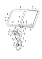
- FIG. 6 It is the perspective view which looked at the handrail, rear-view mirror apparatus, and front-view mirror apparatus by the 2nd Embodiment of this invention from the same position as FIG. It is a perspective view which shows the handrail in FIG. 6, a rear-view mirror apparatus, and a front-view mirror apparatus. It is the disassembled perspective view which looked at the state which isolate
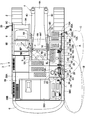
- FIG. 1 to FIG. 5 show a first embodiment of a construction machine according to the present invention.
- a hydraulic excavator 1 constitutes a construction machine used for excavation work of earth and sand.
- the hydraulic excavator 1 is provided with a self-propelled crawler-type lower traveling body 2, an upper revolving body 3 that is turnably mounted on the lower traveling body 2, and an upper revolving body 3 that can be raised and lowered.
- the front device 4 the front device 4.
- the front device 4 includes a boom 4A attached to the front side of a swing frame 5 to be described later, an arm 4B attached to the tip of the boom 4A so as to move up and down, and a front end of the arm 4B.
- the bucket 4C is movably attached, and includes a boom cylinder 4D, an arm cylinder 4E, and a bucket cylinder 4F that drive the bucket 4C.
- the boom 4A is pivotally attached to the left and right vertical plates 5B and 5C of the revolving frame 5 described later.
- the left and right boom cylinders 4D are pivotally attached to the cylinder bracket 5E at the base end side.
- the front device 4 has, for example, a posture in which the boom 4A is tilted deeply to excavate a deep hole (most fully movable position), and excavation at a high position, as indicated by a two-dot chain line in FIG.
- the boom 4A is swung up and down with the posture (the highest lifting position) which is raised by rotating the boom 4A to the rearmost side.
- the revolving frame 5 constitutes a support structure for the upper revolving structure 3.
- the revolving frame 5 as a support structure has a thick flat plate-like bottom plate 5A extending in the front and rear directions, and is erected on the bottom plate 5A, and has a predetermined interval in the left and right directions. Attached to the front and rear of the left and right vertical plates 5B and 5C extending in the front and rear directions, and a plurality of protruding beams extending outward in the left and right directions from the vertical plates 5B and 5C.
- a left side frame (not shown) extending in the direction and a right side frame 5D (see FIG. 1) are configured.
- a cylinder bracket 5E to which the base end side of the boom cylinder 4D is attached is provided on the front side of each of the vertical plates 5B and 5C.
- the counterweight 6 is provided on the rear side of the turning frame 5. This counterweight 6 balances the weight with the front device 4 and is formed as a heavy object having a circular arc on the rear side.
- the engine 7 is located on the front side of the counterweight 6 and mounted on the rear side of the turning frame 5 (illustrated by a dotted line in FIG. 1).
- the engine 7 is mounted on the revolving frame 5 in a horizontally placed state extending in the left and right directions.
- a hydraulic pump 8 is attached to the right side of the engine 7.
- the hydraulic pump 8 is driven by the engine 7 to supply hydraulic oil from a hydraulic oil tank 10 described later to hydraulic actuators such as a traveling motor of the lower traveling body 2 and the cylinders 4D, 4E, and 4F of the front device 4. It is discharged as pressure oil toward
- the cab 9 is provided on the front side of the revolving frame 5 and on the left side which is one side of the left and right directions with the foot part 4A1 of the boom 4A interposed therebetween.
- the cab 9 is formed of a box-like body extending in the front and rear directions, and has a front window 9A, a rear window, a left window (both not shown), and a right window for securing a peripheral field of view. 9B is provided.
- a cab handrail 9 ⁇ / b> C is provided so as to be gripped when moving up and down to the upper swing body 3 and extending upward and downward.
- a driver's seat 9D Inside the cab 9, a driver's seat 9D, various operation levers and the like (not shown) are arranged.
- the driver's seat 9D is seated by an operator, and has an eye point EP at a position where the operator's head is disposed.
- the actual eye point of the operator cannot be determined at a single point because the head is swung left, right, up, or down.
- the eye point EP has an average position. This makes it easy to understand the position of the eye line EL described later.
- the hydraulic oil tank 10 is disposed on the other side position in the left and right directions across the foot portion 4A1 of the boom 4A constituting the front device 4, that is, on the right side (outside) of the right vertical plate 5C of the swivel frame 5. . Furthermore, the hydraulic oil tank 10 is located on the front side of the engine 7 that is obliquely behind the cab 9.
- the hydraulic oil tank 10 is formed as a rectangular parallelepiped pressure vessel extending in the upward and downward directions, and constitutes an oil storage tank of the present invention. As shown in FIG. 4, a work handrail 23 to be described later is attached to the upper surface 10 ⁇ / b> A of the hydraulic oil tank 10 so as to be located outside in the left and right directions.
- the fuel tank 11 is disposed on the right side of the right vertical plate 5C of the revolving frame 5 on the front side of the hydraulic oil tank 10.
- This fuel tank 11 is formed as a rectangular parallelepiped container extending upward and downward, and constitutes the oil storage tank of the present invention together with the hydraulic oil tank 10.
- a fuel supply port 11 ⁇ / b> B for supplying fuel is provided on the upper surface 11 ⁇ / b> A of the fuel tank 11.
- a work front handrail 18, which will be described later is attached on the outside in the left and right directions so as to be continuous with the work handrail 23 in the front and rear directions.
- an attachment member 16 for a lifting handrail 14 to be described later is attached to the front end portion of the upper surface 11A that is on the front side of the front handrail 18 for work.
- the lowermost step 12 is provided so as to protrude from the right front end of the revolving frame 5 (see FIG. 2).
- the lowermost step 12 is a first step that is used when the user steps up and down on the upper swing body 3.
- the article storage case 13 is located on the front side of the fuel tank 11 and is provided on the right front side of the revolving frame 5.
- a tool or the like can be stored in the article storage case 13.
- the upper surface and the front surface of the article storage case 13 are a second step 13A located on the front side and a third step 13B located on the rear side of step 13A.
- the operator can easily ascend on the upper swing body 3 by stepping on the lowermost step 12 and the steps 13A and 13B of the article storage case 13 in order from the lower traveling body 2.
- an operation in the reverse order is performed, it is possible to descend from the upper swing body 3 to the ground.
- the elevating handrail 14 is disposed along the outside of the article storage case 13 between the front end portion of the revolving frame 5 and the front position of the fuel tank 11.
- the elevating handrail 14 is secured when the operator moves up and down to the upper swing body 3 by using the lower step 12 and the steps 13A and 13B of the article storage case 13 as a foothold, thereby assuring safety during raising and lowering.
- the lifting handrail 14 includes a handrail member 15, an attachment member 16, and a reinforcing member 17.
- the handrail member 15 is formed by bending a cylindrical pipe material or the like, and is provided between the front end of the revolving frame 5 and the front position of the fuel tank 11.
- the handrail member 15 includes a front pipe portion 15A extending upward from the right side of the lowermost step 12 at the front end of the revolving frame 5, and an inclined pipe portion extending obliquely rearward upward from the upper end portion of the front pipe portion 15A.
- the lower end portion of the front pipe portion 15 ⁇ / b> A is bolted to the front end of the swivel frame 5.
- the inclined pipe portion 15B and the upper pipe portion 15C are disposed at a height position at which the operator can grip the lower step 12 and the steps 13A and 13B of the article storage case 13 when moving up and down. Has been.
- the attachment member 16 is integrally attached to the lower end portion of the rear pipe portion 15D of the handrail member 15 by using a fixing means such as welding.
- the attachment member 16 is formed, for example, by bending the lower part of one plate material in an L shape in the front side.
- the attachment member 16 serves as a bracket for fixing the rear side of the handrail member 15 to the upper surface 11A of the fuel tank 11, and is bolted to, for example, the frontmost portion of the upper surface 11A.
- the reinforcing member 17 extends from the mounting member 16 to the front side, and its front end is fixed to the inclined pipe portion 15B of the handrail member 15.
- the reinforcing member 17 increases the strength of the handrail member 15 and is formed of a cylindrical pipe material or the like, similar to the handrail member 15.
- the front handrail 18 for work is disposed in the upper position of the fuel tank 11 so as to extend forward and rearward along the outside of the fuel tank 11, and is fixed to the upper surface 11 ⁇ / b> A of the fuel tank 11. That is, the front handrail 18 for work is located outside the fuel tank 11 in the left and right directions, and is disposed so as to continue to the rear of the handrail 14 for raising and lowering.
- the front handrail 18 for work is provided in order to ensure safety when the worker works on the fuel tank 11.
- the work handrail 18 includes a handrail member 19, a front mounting member 20, a rear mounting member 21, and a reinforcing member 22.
- the handrail member 19 is formed by using a cylindrical pipe material or the like like the handrail member 15 of the elevating handrail 14 and bending the pipe material into a gate shape.
- the handrail member 19 includes an upper pipe portion 19A extending frontward and rearward at substantially the same height as the upper pipe portion 15C of the handrail member 15 constituting the elevating handrail 14, and a front end of the upper pipe portion 19A.
- a front pipe portion 19B extending downward from the upper portion and a rear pipe portion 19C extending downward from the rear end portion of the upper pipe portion 19A are formed.
- the front attachment member 20 is integrally attached to the lower end portion of the front pipe portion 19B of the handrail member 19 using a fixing means such as welding.
- the front mounting member 20 is formed, for example, by bending the lower part of one plate material in an L shape on the rear side.
- the front mounting member 20 serves as a bracket for fixing the front side of the handrail member 15 to the upper surface 11A of the fuel tank 11, and is bolted to, for example, a front portion of the upper surface 11A.
- the front mounting member 20 is provided in the vicinity of the mounting member 16 of the elevating handrail 14.
- the rear attachment member 21 is integrally attached to the lower end portion of the rear pipe portion 19C of the handrail member 19 using welding means or the like so as to face the front attachment member 20 in the front and rear directions.
- the rear mounting member 21 is formed in the same manner as the front mounting member 20 by, for example, bending the lower part of one plate material in an L shape to the front side.
- the rear attachment member 21 serves as a bracket for fixing the rear side of the handrail member 19 to the upper surface 11A of the fuel tank 11, and is bolted to the rear portion of the upper surface 11A, for example.
- the reinforcing member 22 is provided to extend substantially parallel to the upper pipe portion 19A at a position spaced downward from the upper pipe portion 19A of the handrail member 19.
- the reinforcing member 22 is formed of a cylindrical pipe material or the like extending in the front and rear directions.
- the front end of the reinforcing member 22 is fixed to the upper and lower intermediate portions of the front pipe portion 19B using welding means or the like, and the rear end is fixed to the upper and lower intermediate portions of the rear pipe portion 19C. .
- the reinforcing member 22 increases the strength of the handrail member 19.
- the rear handrail 23 for work is arranged at the upper position of the hydraulic oil tank 10 so as to extend forward and rearward along the hydraulic oil tank 10, and is fixed to the upper surface 10 ⁇ / b> A of the hydraulic oil tank 10. Accordingly, the rear handrail 23 for work is disposed so as to be connected to the rear of the front handrail 18 for work.
- the work handrail 23 is provided to ensure safety when the worker works on the hydraulic oil tank 10.
- the rear handrail 23 for work has the same basic structure as the front handrail 18 for work described above, only having a smaller front and rear dimension.
- the work rear handrail 23 is similar to the work front handrail 18 in that the handrail member 24 includes the upper pipe portion 24A, the front pipe portion 24B, and the rear pipe portion 24C, and the front pipe portion 24B of the handrail member 24.
- a front attachment member 25 attached to the lower end portion of the rail
- a rear attachment member 26 attached to the lower end portion of the rear pipe portion 24C of the handrail member 24, an intermediate portion of the front pipe portion 24B and an intermediate portion of the rear pipe portion 24C.
- a reinforcing member 27 fixed to the head.
- the front mounting member 25 is bolted to the front side portion of the upper surface 10A of the hydraulic oil tank 10 and the rear mounting member 26 is bolted to the rear side portion of the upper surface 10A of the hydraulic oil tank 10.
- the work rear handrail 23 is provided at the upper position of the hydraulic oil tank 10.
- the front mounting member 25 is provided in the vicinity of the rear mounting member 21 of the work handrail 18.
- the rear handrail 23 for work is provided at the upper position of the hydraulic oil tank 10
- most of the rear handrail 23 for work may be disposed on the upper side of the hydraulic oil tank 10. That is, as long as the rear handrail 23 for work is disposed on the upper side of the hydraulic oil tank 10, the front mounting member 25 may be mounted on the fuel tank 11, and the rear mounting member 26 may be attached to an exterior cover 38 described later. It may be attached to the upper surface cover portion 38A.
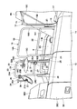
- the main side mirror device 28 is provided on the right side of the cab 9 with the foot portion 4A1 of the boom 4A constituting the front device 4 interposed therebetween. Specifically, the main side mirror device 28 is located on the front side of the article storage case 13 and is provided on the right side of the lowermost step 12. Specifically, the main side mirror device 28 is attached to the elevating handrail 14 disposed at the right front corner of the upper swing body 3. The main side mirror device 28 is for visually observing the rear side including the hydraulic oil tank 10 and the fuel tank 11 from the inside of the cab 9, that is, the right side portion of the upper swing body 3 and its periphery.
- the base side of the main side mirror device 28 is attached to the front pipe portion 15A of the handrail member 15 that constitutes the lifting handrail 14. That is, the main side mirror device 28 includes a stay 28A having a distal end extending leftward and rightward (right) and a mirror main body 28B attached to the distal end of the stay 28A.
- the main side mirror device 28 adjusts the mounting angle between the stay 28A and the mirror main body 28B, and the right side portion of the upper swing body 3 that cannot be directly seen by an operator who has boarded the cab 9 and its side
- the surrounding area can be reflected.
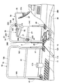
- the visible range in this case is, for example, the visible range A surrounded by a solid line in FIG.
- the operator in the cab 9 can visually recognize the right side portion of the upper swing body 3 by visually observing the main side mirror device 28.
- the boom 4A and the boom cylinder 4D of the front device 4 are arranged between the cab 9 and the main side mirror device 28, the boom 4A and the boom cylinder 4D of the front device 4 are arranged. Therefore, as shown in FIG. 1, in the state where the boom 4A is tilted forward, the operator in the cab 9 can see the main side mirror device 28 by being blocked by the foot portion 4A1 of the boom 4A or the boom cylinder 4D. Disappear.
- each of the rear-view mirror device 29 and the front-view mirror device 34 will be described.
- the rear-view mirror device 29 and the front-view mirror device 34 are obstructed by the front device 4 and when the main side mirror device 28 cannot be seen from the cab 9, the right side portion of the upper swing body 3 and its periphery are visually observed. Is provided to do.
- the rear-view mirror device 29 is for visually observing the rear of the hydraulic oil tank 10 located in the middle between the front and rear direction of the upper swing body 3 (on the right side and rear side of the upper swing body 3). Is provided.
- the rearview mirror device 29 includes a clamp member 30, a stay 31, a mirror body 32, and a positioning member 33, which will be described later.
- the rear-view mirror device 29 is disposed at a position where the rear side mirror device 28 can be seen from inside the cab 9 while avoiding the front device 4 when the main side mirror device 28 cannot be seen from inside the cab 9 due to the posture of the front device 4. Yes. Specifically, as shown by a two-dot chain line in FIG. 1, in a posture in which the boom 4A of the front device 4 rises to the rearmost side, the rear end of the foot portion 4A1 of the boom 4A is the rear-view mirror device 29. Can be an obstacle to visual inspection.
- the left corner portion on the cab 9 side of the left and right rear ends of the foot portion 4A1 is set as a point P.
- the rear-view mirror device 29 has a straight line connecting the eye point EP of the operator in the cab 9 and the point P at the left corner of the foot portion 4A1 of the boom 4A that rises to the rearmost side.
- the line of sight is EL
- the rearview mirror device 29 is arranged in a range in front of the straight line EA.
- This straight line EA is the eye movement position when the operator in the cab 9 turns back and looks back, and is set to a position rotated backward by an angle ⁇ from the position of the eye point EP of the operator.
- the angle ⁇ is currently set to 45 ° rearward (135 ° clockwise or counterclockwise from the immediately preceding side) according to JIS standards.
- the clamp member 30 is attached to the front portion of the reinforcing member 27 that constitutes the rear handrail 23 for work.
- the clamp member 30 includes a pair of first clamp 30A and second clamp 30B that are arranged to face each other with the reinforcing member 27 interposed therebetween, and the first clamp 30A and the second clamp 30B so as to sandwich the reinforcing member 27.
- a plurality of screwed, for example, two bolts 30C are used.
- the clamp member 30 is fixed to the reinforcing member 27 by tightening each bolt 30C. Thereby, the clamp member 30 can adjust the angle of the mirror main body 32 described later in the circumferential direction of the reinforcing member 27 in a state where each bolt 30C is loosened.
- the stay 31 is formed of a pipe material or a bar material attached to the first clamp 30A of the clamp member 30.
- the base 31 of the stay 31 is attached to the reinforcing member 27 of the rear handrail 23 for work via the clamp member 30. Furthermore, the stay 31 extends in the radial direction of the reinforcing member 27, then bends in an L shape and extends rearward, and a mirror body 32 is provided on the tip side thereof.
- the mirror body 32 is provided on the tip side of the stay 31.
- the mirror body 32 has a mirror surface on the front side, and a joint portion 32A is provided on the back side.
- the joint portion 32 ⁇ / b> A can adjust the mounting angle of the mirror main body 32, and can fix the angle and position with respect to the stay 31 in a tightened state. Thereby, the mirror main body 32 can adjust the angle with respect to the stay 31 by the joint part 32A.
- the mirror main body 32 is arranged at a position (position shown in FIGS. 3 and 4) where the stay 31 is tilted to the outside in the left and right directions.
- This position is the basic position of the rearview mirror device 29 that is arranged during normal operation.
- the rearview mirror device 29 can be folded to the rear handrail 23 side by loosening the clamp member 30, and this state is such that the rearview mirror device 29 does not protrude during transportation. This is the transport position stored on the slide 23 side.
- the rear-view mirror device 29 is arranged at the basic position so that the rear-view mirror device 29 is arranged on the rear side of the operator's eye line EL in the cab 9, so that the boom 4A of the front device 4 rises to the rearmost side. Even in the state of taking the posture, it can be visually observed from inside the cab 9.
- the visible range of the rearview mirror device 29 at this time is, for example, a visible range B surrounded by a two-dot chain line in FIG.
- the positioning member 33 prevents the rearview mirror device 29 from rotating below the basic position described above due to its own weight or vibration accompanying the operation of the vehicle body, and is positioned at this basic position. It is.
- the positioning member 33 is fixed to the reinforcing member 27 of the work handrail 23 by welding means or the like.
- the positioning member 33 is configured by a block body that is located between the clamps 30 ⁇ / b> A and 30 ⁇ / b> B of the clamp member 30 and protrudes outward in the radial direction of the reinforcing member 27.
- the positioning member 33 comes into contact with the second clamp 30B at this basic position, so that the rearview mirror device is at this position. 29 can be positioned.
- the rearview mirror device 29 can be held at the basic position, and a troublesome positioning operation when returning from the transport position to the basic position can be omitted.
- the front-view mirror device 34 visually observes the front of the hydraulic oil tank 10 located in the middle of the front and rear direction of the upper swing body 3 (on the right side and forward of the upper swing body 3). Is provided. Similar to the rear-view mirror device 29, the front-view mirror device 34 includes a clamp member 35, a stay 36, a mirror body 37, and the like, which will be described later. Since the front-view mirror device 34 has substantially the same configuration as the rear-view mirror device 29, the description thereof will be simplified.
- the front-view mirror device 34 is arranged behind the operator's eye line EL in the cab 9. On the other hand, the front-view mirror device 34 is disposed in a range on the front side of the straight line EA that is the position of movement to the rear of the eyes.
- the clamp member 35 is attached to the upper part of the rear pipe portion 24 ⁇ / b> C constituting the handrail member 24 of the work handrail 23.
- the clamp member 35 includes a pair of first clamp 35A, second clamp 35B, and bolt 35C, similarly to the clamp member 30 of the rearview mirror device 29.
- the clamp member 35 is fixedly attached to the rear pipe portion 24C, and the angle of a mirror main body 37 to be described later is adjusted in the circumferential direction (horizontal direction) of the rear pipe portion 24C in a state where each bolt 35C is loosened. be able to.
- the stay 36 is formed of a pipe material or a bar material attached to the first clamp 35 ⁇ / b> A of the clamp member 35.
- the base end side of the stay 36 is attached to the rear pipe portion 24 ⁇ / b> C of the handrail member 24 via the clamp member 35. Further, the stay 36 extends in the radial direction of the rear pipe portion 24C, then bends in an L shape and extends downward.
- the mirror body 37 is provided on the tip side of the stay 36.
- the mirror main body 37 has a mirror surface on the front side and a joint portion 37A on the back side in substantially the same manner as the mirror main body 32 of the rearview mirror device 29.
- the mirror body 37 is attached to the stay 36 via a joint portion 37A so that the angle can be adjusted.
- the mirror main body 37 is disposed at a position (position shown in FIGS. 3 and 4) where the stay 36 is rotated leftward and rightward.
- This position is the basic position of the foreground mirror device 34 that is disposed during normal operation.
- the front-view mirror device 34 can be arranged at the transport position stored by rotating to the left so that the front-view mirror device 34 does not protrude during transport by loosening the clamp member 35.
- the front-view mirror device 34 is disposed behind the operator's line of sight EL in the cab 9 in a state of being disposed at the basic position, similarly to the rear-view mirror device 29. Therefore, the front-view mirror device 34 can be viewed from inside the cab 9 even when the boom 4A is in a standing posture.
- the visible range of the front-view mirror device 34 at this time is, for example, a visual range C surrounded by a one-dot chain line in FIG.
- the operator in the cab 9 visually observes the visual range B of the rear-view mirror device 29 and the visual range C of the front-view mirror device 34 by viewing the rear-view mirror device 29 and the front-view mirror device 34. Can do. Thus, even when the main side mirror device 28 cannot be viewed with the front device 4, the viewing range A of the main side mirror device 28 is changed to the viewing range B of the rear view mirror device 29 and the viewing range C of the front view mirror device 34. And can be supplemented by.
- the front-view mirror device 34 can be provided with a positioning member similar to the positioning member 33.
- this positioning member it is possible to prevent positional displacement of the front-view mirror device 34 due to vibration or the like, and it is possible to omit troublesome positioning work when returning from the transport position to the basic position.
- the exterior cover 38 is provided in a range from the rear side of the cab 9 to the counterweight 6.
- the exterior cover 38 includes an upper surface cover portion 38A that covers the engine 7 and the like, a left surface cover portion 38B that extends downward from the left end of the upper surface cover portion 38A, and a lower surface that extends downward from the right end of the upper surface cover portion 38A.
- a right cover portion 38C and an openable and closable engine cover portion 38D provided on the upper surface cover portion 38A.
- the cab mirror device 39 is provided on the cab handrail 9C of the cab 9.
- the cab mirror device 39 is configured in substantially the same manner as the main side mirror device 28.
- the cab mirror device 39 visually observes the rear side including the left side of the upper swing body 3 from the cab 9.
- the hydraulic excavator 1 according to the first embodiment has the above-described configuration. Next, the operation of the hydraulic excavator 1 will be described.
- the operator gets on the cab 9 and sits in the driver's seat 9D.
- the lower traveling body 2 can be driven to move the hydraulic excavator 1 forward or backward.
- an operator seated in the driver's seat 9D can perform earth excavation work and the like by moving the front device 4 up and down by operating an operation lever.
- the foot part 4A1 and the boom cylinder 4D of the boom 4A constituting the front device 4 are arranged. Therefore, in a state where the boom 4A of the front device 4 is tilted forward, that is, in the state of the front device 4 shown in FIG. 1, the line of sight when viewing the main side mirror device 28 from the cab 9 is viewed by the foot portion 4A1 and the like. It will be blocked. Thereby, the operator in the cab 9 cannot see the right side part of the upper swing body 3 and its periphery.
- the working rear handrail 23 is provided at the upper position of the hydraulic oil tank 10 that constitutes the oil storage tank to be gripped when moving up and down to the upper swing body.
- the rear handrail 23 for work is provided with a rear-view mirror device 29 for visually observing the rear of the hydraulic oil tank 10 (on the right side and the rear of the upper swing body 3), and in front of the hydraulic oil tank 10 (upper part).
- a front-view mirror device 34 for visually observing the right side and the front side of the revolving structure 3 is provided.
- the front device 4 when viewing the main side mirror device 28 from inside the cab 9, the front device 4 may be obstructed and the main side mirror device 28 may not be visible.
- the operator in the cab 9 visually observes the rear-view mirror device 29 and the front-view mirror device 34 arranged on the right rear side, so that the right side position of the upper swing body 3, that is, the rear view.
- the viewing range B of the mirror device 29 and the viewing range C of the front-view mirror device 34 can be viewed.
- the viewing range A of the main side mirror device 28 is changed from the viewing range B of the rear view mirror device 29 to the front view mirror device 34.
- This can be compensated by the visual range C.
- the operator in the cab 9 visually observes the main side mirror device 28, the rear view mirror device 29, and the front view mirror device 34, so that the hydraulic oil tank 10, fuel
- the side part of the upper swing body 3 including the tank 11 and its periphery can be visually observed, and the safety during work can be improved.
- the rear-view mirror device 29 and the front-view mirror device 34 are such that the boom 4A of the front device 4 rises to the rearmost side, the operator's eyepoint EP in the cab 9 and the rear of the boom 4A of the front device 4 It is arranged behind the position of the eye line EL connecting the point P at the left corner as the end. Therefore, the rear-view mirror device 29 and the front-view mirror device 34 can always be viewed from inside the cab 9 regardless of the working posture of the front device 4.
- the rearview mirror device 29 includes a stay 31 attached to the reinforcing member 27 of the rear handrail 23 for work on the proximal end side, and a mirror main body 32 provided on the distal end side of the stay 31.
- the front-view mirror device 34 includes a stay 36 attached to the rear pipe portion 24C of the handrail member 24 whose base end side constitutes the rear handrail 23 for work, and a mirror main body 37 provided on the front end side of the stay 36. It is comprised including.
- the mirror body 32 of the rearview mirror device 29 and the mirror body 37 of the frontview mirror device 34 can each adjust the angle with respect to the work rear handrail 23.
- the rearview mirror device 29 can appropriately adjust the viewing range B reflected on the mirror main body 32 according to the physique of the operator, the situation at the work site, and the like.
- the front-view mirror device 34 can appropriately adjust the viewing range C reflected on the mirror body 37. That is, the rearview mirror device 29 can obtain an optimum field of view according to the situation.
- each mirror device 29, 34 is attached at a position excluding the upper pipe portion 24A of the rear handrail 23 for work, it is possible to secure a sufficient margin for gripping the handrail, and to turn the operator upward. It is possible to ensure safety during work and movement on the body 3.
- the stay 31 is provided with a clamp member 30 for fixing to the rear handrail 23 for work.
- the stay 36 is provided with a clamp member 35 for fixing to the rear handrail 23 for work.
- a positioning member 33 for positioning the clamp member 30 is provided on the reinforcing member 27 of the rear handrail 23 for work. Therefore, the positioning member 33 can position the rear-view mirror device 29 at the basic position where the rear-view mirror device 29 is tilted outward in the left and right directions. Moreover, even if vibrations or the like are applied during operation, the rearview mirror device 29 can be held at the basic position, so that safety during work can be improved. Further, the troublesome positioning work for returning the rearview mirror device 29 from the transport position stored on the rear handrail 23 side to the basic position can be omitted.
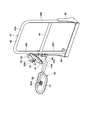
- FIGS. 6 to 8 show a construction machine according to a second embodiment of the present invention.
- a feature of the present embodiment is that the handrail is provided with a handrail-side mirror mount, and the handrail-side mirror mount is supported by a common mirror in which a rearview mirror device and a frontview mirror device are supported.
- a support is provided, and the handrail side mirror mount and the common mirror support are fixed using a screw member.
- the same components as those in the first embodiment described above are denoted by the same reference numerals, and description thereof is omitted.
- the rear handrail 41 for work according to the second embodiment is substantially the same as the rear handrail 23 for work according to the first embodiment, along the hydraulic oil tank 10 at the upper position of the hydraulic oil tank 10. It is fixed to the upper surface 10A of the hydraulic oil tank 10 in a state extending in the front and rear directions.
- the work rear handrail 41 includes a handrail member 42 including an upper pipe portion 42A, a front pipe portion 42B, and a rear pipe portion 42C, and a front pipe portion 42B of the handrail member 42.
- the reinforcing member 45 is fixed to the reinforcing member 45.
- the rear handrail 41 for work according to the second embodiment is in accordance with the first embodiment in that a handrail side mirror attachment 46 described later is provided on the rear pipe portion 42C of the handrail member 42. This is different from the rear handrail 23 for work.
- the rear pipe portion 42C of the handrail member 42 has a columnar solid portion 42C1 on the lower side from the intermediate portion in the upper and lower directions in order to ensure the strength for welding the handrail side mirror attachment 46. It has become.
- the solid portion 42C1 it is also possible to increase the strength against welding by increasing the thickness dimension of the pipe member from the upper and lower intermediate portions to the lower side.
- the handrail-side mirror fixture 46 of the rear handrail 41 for work is formed of a rectangular flat plate elongated in the left and right directions, and is fixed to the rear pipe portion 42C of the handrail member 42 using welding means. .
- the handrail-side mirror fixture 46 is provided on the rear upper side of the solid part 42C1 of the rear pipe part 42C at a position facing the reinforcing member 45. Accordingly, the entire deformation (curvature, warpage, etc.) of the rear pipe portion 42 ⁇ / b> C that occurs when the handrail-side mirror fixture 46 is welded to the rear pipe portion 42 ⁇ / b> C can be suppressed by the reinforcing member 45. Further, the partial deformation of the rear pipe portion 42C can be suppressed by the solid portion 42C1.
- the handrail side mirror attachment 46 is provided with a plurality of, for example, three female screw holes 46A, for example, at positions sandwiching the rear pipe portion 42C.
- a common mirror support 47 (rear-view mirror device 49, front-view mirror device 52) described later is not rotated on the handrail-side mirror mount 46. So that it can be firmly fixed.
- the common mirror support 47 is provided so as to face the handrail side mirror attachment 46 of the rear handrail 41 for work.
- the common mirror support 47 is a contact plate portion 47A made of a flat plate in surface contact with the handrail side mirror mount 46, and is bent in an L shape from the right end portion of the contact plate portion 47A and extends rearward. Arm portion 47B.
- the contact plate portion 47A is provided with a bolt insertion hole 47C at a position corresponding to each female screw hole 46A of the handrail side mirror attachment 46.
- the common mirror support 47 is a bolt 48 as a screw member inserted into each bolt insertion hole 47C in a state in which the contact plate portion 47A is in contact (surface contact) with the handrail-side mirror attachment 46 from the rear surface side. Is screwed into the female screw hole 46A of the handrail side mirror attachment 46. Thereby, the common mirror support 47 can be integrally attached to the handrail-side mirror attachment 46. In this state, the rearview mirror device 49 and the frontview mirror device 52 are supported by the common mirror support 47.
- the rear-view mirror device 49 according to the second embodiment is similar to the rear-view mirror device 29 according to the first embodiment in that the hydraulic oil tank 10 is located in the middle between the front and rear directions of the upper swing body 3.
- the rear side (right side and rear side of the upper swing body 3) is visually observed, and is provided on the rear handrail 41 for work.
- the rearview mirror device 49 includes a stay 50 and a mirror main body 51.
- the operator in the cab 9 turns around the rear side and visually observes the oblique rear right side.
- the rear-view mirror device 49 is arranged in a range in front of the straight line EA described in the first embodiment.
- the stay 50 is formed of a pipe material or a bar material attached to the common mirror support 47.
- the base 50 (front end) of the stay 50 is attached to the arm portion 47B of the common mirror support 47 using welding means or the like.
- the stay 50 is provided with a mirror main body 51 on the front end side extending linearly rearward.
- the mirror body 51 is provided on the tip side of the stay 50.
- This mirror main body 51 has a mirror surface on the front side and a joint portion 51A on the back side in substantially the same manner as the mirror main body 32 according to the first embodiment.
- the mirror body 51 is attached to the stay 50 via the joint portion 51A so that the angle can be adjusted.
- the front-view mirror device 52 is for visually observing the front of the hydraulic oil tank 10 located in the middle between the front and rear of the upper swing body 3 (on the right side and the front of the upper swing body 3). Is provided.
- the front-view mirror device 52 includes a stay 53 and a mirror main body 54 which will be described later.
- the front-view mirror device 52 is similar to the rear-view mirror device 49 when the operator in the cab 9 visually observes the right rear side of the foot 4A1 of the boom 4A that rises to the rearmost side. It is arranged behind the position of a straight line (line of sight) passing through the rear end.
- the front-view mirror device 52 is disposed in a range in front of the straight line EA.
- the stay 53 is formed of a pipe material or a bar material attached to the common mirror support 47.
- the stay 53 is attached to the contact plate portion 47A of the common mirror support 47 using welding means or the like on the base end side (lower end side) extending upward and downward.
- a mirror main body 54 is provided on the tip side of the stay 53 that is bent in an L shape and extends to the right.
- the mirror body 54 is provided on the tip side of the stay 53.
- the mirror main body 54 has a front-side mirror surface and a rear-side joint portion 54A, almost the same as the mirror main body 51 described above.
- the mirror main body 54 is attached to the stay 53 via the joint portion 54A so that the angle can be adjusted.
- the rearview mirror device 49 has a viewing range equivalent to the viewing range B of the rearview mirror device 29 according to the first embodiment.
- the front-view mirror device 52 has a viewing range equivalent to the viewing range C of the front-view mirror device 34 according to the first embodiment.
- the viewing range A of the main side mirror device 28 described above can be supplemented by the viewing range of the rearview mirror device 49 and the viewing range of the frontview mirror device 52.
- the handrail 41 for work is provided with the handrail-side mirror attachment 46.
- the handrail side mirror mount 46 is provided with a common mirror support on which the rearview mirror device 49 and the frontview mirror device 52 are supported.
- the handrail side mirror mounting tool 46 and the common mirror support tool 47 are fixed using bolts 48.
- the handrail-side mirror mount 46 and the common mirror support 47 can be fixed by the respective bolts 48 while being in surface contact with each other. Therefore, compared with the case where a clamp member is attached to a pipe, since the position shift by vibration etc. can be suppressed, a favorable visual field can be provided stably and safety can be improved.
- the handrail side mirror attachment 46 of the work rear handrail 41 is provided at a position facing the reinforcing member 45 in the rear pipe portion 42C, the rear side when the handrail side mirror attachment 46 is welded.
- the deformation (curvature, warpage, etc.) of the entire pipe portion 42 ⁇ / b> C can be suppressed by the reinforcing member 45.
- the handrail side mirror attachment 46 is welded to the solid portion 42C1 of the rear pipe portion 42C, partial deformation can also be suppressed.
- the handrail-side mirror attachment 46 made of a flat plate can be easily attached to the rear pipe portion 42C, and the size of the female screw hole 46A can be appropriately set.
- the size of the bolt 48 is increased. Mounting strength can be increased.
- the work rear handrail 23 is provided at the upper position of the hydraulic oil tank 10 as an oil storage tank, and the rear view mirror device 29 and the front view mirror device 34 are provided on the work rear handrail 23.
- the present invention is not limited to this, and the rear handrail 23 for work is provided on the upper position of the fuel tank 11 as an oil storage tank, and the rearview mirror device 29 and the frontview mirror device 34 are provided on the rear handrail 23 for work. It is good.
- This configuration can also be applied to the second embodiment.
- the crawler type hydraulic excavator 1 is described as an example of the construction machine.
- the present invention is not limited to this, and can be widely applied to other construction machines such as a wheeled hydraulic excavator and a hydraulic crane.
Landscapes
- Engineering & Computer Science (AREA)
- Multimedia (AREA)
- Mechanical Engineering (AREA)
- Mining & Mineral Resources (AREA)
- Civil Engineering (AREA)
- General Engineering & Computer Science (AREA)
- Structural Engineering (AREA)
- Rear-View Mirror Devices That Are Mounted On The Exterior Of The Vehicle (AREA)
- Component Parts Of Construction Machinery (AREA)
Applications Claiming Priority (2)
| Application Number | Priority Date | Filing Date | Title |
|---|---|---|---|
| JP2016-063843 | 2016-03-28 | ||
| JP2016063843A JP6567453B2 (ja) | 2016-03-28 | 2016-03-28 | 建設機械 |
Publications (1)
| Publication Number | Publication Date |
|---|---|
| WO2017168784A1 true WO2017168784A1 (ja) | 2017-10-05 |
Family
ID=59963914
Family Applications (1)
| Application Number | Title | Priority Date | Filing Date |
|---|---|---|---|
| PCT/JP2016/075993 Ceased WO2017168784A1 (ja) | 2016-03-28 | 2016-09-05 | 建設機械 |
Country Status (2)
| Country | Link |
|---|---|
| JP (1) | JP6567453B2 (enExample) |
| WO (1) | WO2017168784A1 (enExample) |
Families Citing this family (1)
| Publication number | Priority date | Publication date | Assignee | Title |
|---|---|---|---|---|
| JP7118866B2 (ja) * | 2018-11-20 | 2022-08-16 | 株式会社加藤製作所 | 建設機械 |
Citations (9)
| Publication number | Priority date | Publication date | Assignee | Title |
|---|---|---|---|---|
| JPH0642419U (ja) * | 1992-11-18 | 1994-06-07 | 株式会社小松製作所 | 走行車両のバックミラー取付構造 |
| JP2002088817A (ja) * | 2000-09-14 | 2002-03-27 | Hitachi Constr Mach Co Ltd | 建設機械の手摺 |
| JP2006290030A (ja) * | 2005-04-06 | 2006-10-26 | Daito Press Kogyo Kk | 建設機械用サイドミラー支持装置 |
| JP2009101787A (ja) * | 2007-10-22 | 2009-05-14 | Komatsu Ltd | ミラー支持装置 |
| JP2009214557A (ja) * | 2008-03-06 | 2009-09-24 | Yanmar Co Ltd | 旋回作業車のサイドミラー装置 |
| JP2010163775A (ja) * | 2009-01-14 | 2010-07-29 | Caterpillar Japan Ltd | 作業機械 |
| JP2012062691A (ja) * | 2010-09-16 | 2012-03-29 | Hitachi Constr Mach Co Ltd | 建設機械 |
| JP2014047564A (ja) * | 2012-08-31 | 2014-03-17 | Hitachi Constr Mach Co Ltd | 建設機械 |
| JP5629015B1 (ja) * | 2013-02-18 | 2014-11-19 | 株式会社小松製作所 | 油圧ショベル |
Family Cites Families (1)
| Publication number | Priority date | Publication date | Assignee | Title |
|---|---|---|---|---|
| KR100861562B1 (ko) * | 2006-11-24 | 2008-10-02 | 볼보 컨스트럭션 이키프먼트 홀딩 스웨덴 에이비 | 접이식 건설중장비용 핸드레일 |
-
2016
- 2016-03-28 JP JP2016063843A patent/JP6567453B2/ja active Active
- 2016-09-05 WO PCT/JP2016/075993 patent/WO2017168784A1/ja not_active Ceased
Patent Citations (9)
| Publication number | Priority date | Publication date | Assignee | Title |
|---|---|---|---|---|
| JPH0642419U (ja) * | 1992-11-18 | 1994-06-07 | 株式会社小松製作所 | 走行車両のバックミラー取付構造 |
| JP2002088817A (ja) * | 2000-09-14 | 2002-03-27 | Hitachi Constr Mach Co Ltd | 建設機械の手摺 |
| JP2006290030A (ja) * | 2005-04-06 | 2006-10-26 | Daito Press Kogyo Kk | 建設機械用サイドミラー支持装置 |
| JP2009101787A (ja) * | 2007-10-22 | 2009-05-14 | Komatsu Ltd | ミラー支持装置 |
| JP2009214557A (ja) * | 2008-03-06 | 2009-09-24 | Yanmar Co Ltd | 旋回作業車のサイドミラー装置 |
| JP2010163775A (ja) * | 2009-01-14 | 2010-07-29 | Caterpillar Japan Ltd | 作業機械 |
| JP2012062691A (ja) * | 2010-09-16 | 2012-03-29 | Hitachi Constr Mach Co Ltd | 建設機械 |
| JP2014047564A (ja) * | 2012-08-31 | 2014-03-17 | Hitachi Constr Mach Co Ltd | 建設機械 |
| JP5629015B1 (ja) * | 2013-02-18 | 2014-11-19 | 株式会社小松製作所 | 油圧ショベル |
Also Published As
| Publication number | Publication date |
|---|---|
| JP2017179731A (ja) | 2017-10-05 |
| JP6567453B2 (ja) | 2019-08-28 |
Similar Documents
| Publication | Publication Date | Title |
|---|---|---|
| US7445272B2 (en) | Upper frame structure for supporting cab of construction machinery | |
| US20180044150A1 (en) | Moving device for counterweight | |
| JP5666234B2 (ja) | 建設機械 | |
| US8998234B2 (en) | Construction machine | |
| US7665801B2 (en) | Structure of upper frame for supporting cabin of construction machinery | |
| JP5865313B2 (ja) | 建設機械 | |
| JP5996122B2 (ja) | 作業車両のキャブ及びその製造方法 | |
| US7987942B2 (en) | Upper frame for excavator | |
| JP2019049117A (ja) | 建設機械 | |
| JP6567453B2 (ja) | 建設機械 | |
| JP2007205100A (ja) | 建設機械の車体フレームおよび建設機械 | |
| JP6847528B2 (ja) | 建設機械 | |
| CN110226009B (zh) | 液压挖掘机 | |
| JP6915952B2 (ja) | 作業機械 | |
| JP6224565B2 (ja) | 建設機械 | |
| JP7085971B2 (ja) | 作業車両 | |
| WO2017183287A1 (ja) | 小型油圧ショベル | |
| WO2005003468A1 (ja) | 建設機械及びその突出物 | |
| JP2007063839A (ja) | 建設機械用保護構造物及び建設機械用キャブ | |
| JP6262118B2 (ja) | 建設機械の旋回フレーム | |
| JP2008063812A (ja) | 建設機械のコンソールボックスの取付け構造 | |
| JP7557414B2 (ja) | 建設機械 | |
| JP7061592B2 (ja) | 作業機械 | |
| JP4920570B2 (ja) | 建設機械におけるキャブ補強構造 | |
| JP2010070939A (ja) | 建設機械 |
Legal Events
| Date | Code | Title | Description |
|---|---|---|---|
| NENP | Non-entry into the national phase |
Ref country code: DE |
|
| 121 | Ep: the epo has been informed by wipo that ep was designated in this application |
Ref document number: 16897001 Country of ref document: EP Kind code of ref document: A1 |
|
| 122 | Ep: pct application non-entry in european phase |
Ref document number: 16897001 Country of ref document: EP Kind code of ref document: A1 |