WO2017164286A1 - 音響機器の設定方法及び音響機器 - Google Patents
音響機器の設定方法及び音響機器 Download PDFInfo
- Publication number
- WO2017164286A1 WO2017164286A1 PCT/JP2017/011645 JP2017011645W WO2017164286A1 WO 2017164286 A1 WO2017164286 A1 WO 2017164286A1 JP 2017011645 W JP2017011645 W JP 2017011645W WO 2017164286 A1 WO2017164286 A1 WO 2017164286A1
- Authority
- WO
- WIPO (PCT)
- Prior art keywords
- configuration
- input
- speaker
- signal processing
- output
- Prior art date
- Legal status (The legal status is an assumption and is not a legal conclusion. Google has not performed a legal analysis and makes no representation as to the accuracy of the status listed.)
- Ceased
Links
Images




Classifications
-
- H—ELECTRICITY
- H03—ELECTRONIC CIRCUITRY
- H03G—CONTROL OF AMPLIFICATION
- H03G3/00—Gain control in amplifiers or frequency changers
- H03G3/002—Control of digital or coded signals
-
- H—ELECTRICITY
- H03—ELECTRONIC CIRCUITRY
- H03G—CONTROL OF AMPLIFICATION
- H03G3/00—Gain control in amplifiers or frequency changers
- H03G3/20—Automatic control
- H03G3/30—Automatic control in amplifiers having semiconductor devices
- H03G3/3005—Automatic control in amplifiers having semiconductor devices in amplifiers suitable for low-frequencies, e.g. audio amplifiers
-
- H—ELECTRICITY
- H03—ELECTRONIC CIRCUITRY
- H03G—CONTROL OF AMPLIFICATION
- H03G3/00—Gain control in amplifiers or frequency changers
- H03G3/20—Automatic control
- H03G3/30—Automatic control in amplifiers having semiconductor devices
- H03G3/3005—Automatic control in amplifiers having semiconductor devices in amplifiers suitable for low-frequencies, e.g. audio amplifiers
- H03G3/3026—Automatic control in amplifiers having semiconductor devices in amplifiers suitable for low-frequencies, e.g. audio amplifiers the gain being discontinuously variable, e.g. controlled by switching
-
- H—ELECTRICITY
- H03—ELECTRONIC CIRCUITRY
- H03G—CONTROL OF AMPLIFICATION
- H03G5/00—Tone control or bandwidth control in amplifiers
- H03G5/16—Automatic control
- H03G5/165—Equalizers; Volume or gain control in limited frequency bands
-
- H—ELECTRICITY
- H03—ELECTRONIC CIRCUITRY
- H03G—CONTROL OF AMPLIFICATION
- H03G7/00—Volume compression or expansion in amplifiers
- H03G7/002—Volume compression or expansion in amplifiers in untuned or low-frequency amplifiers, e.g. audio amplifiers
-
- H—ELECTRICITY
- H04—ELECTRIC COMMUNICATION TECHNIQUE
- H04R—LOUDSPEAKERS, MICROPHONES, GRAMOPHONE PICK-UPS OR LIKE ACOUSTIC ELECTROMECHANICAL TRANSDUCERS; ELECTRIC HEARING AIDS; PUBLIC ADDRESS SYSTEMS
- H04R3/00—Circuits for transducers
- H04R3/12—Circuits for transducers for distributing signals to two or more loudspeakers
- H04R3/14—Cross-over networks
-
- H—ELECTRICITY
- H03—ELECTRONIC CIRCUITRY
- H03G—CONTROL OF AMPLIFICATION
- H03G2201/00—Indexing scheme relating to subclass H03G
- H03G2201/10—Gain control characterised by the type of controlled element
- H03G2201/103—Gain control characterised by the type of controlled element being an amplifying element
-
- H—ELECTRICITY
- H04—ELECTRIC COMMUNICATION TECHNIQUE
- H04R—LOUDSPEAKERS, MICROPHONES, GRAMOPHONE PICK-UPS OR LIKE ACOUSTIC ELECTROMECHANICAL TRANSDUCERS; ELECTRIC HEARING AIDS; PUBLIC ADDRESS SYSTEMS
- H04R3/00—Circuits for transducers
- H04R3/04—Circuits for transducers for correcting frequency response
-
- H—ELECTRICITY
- H04—ELECTRIC COMMUNICATION TECHNIQUE
- H04R—LOUDSPEAKERS, MICROPHONES, GRAMOPHONE PICK-UPS OR LIKE ACOUSTIC ELECTROMECHANICAL TRANSDUCERS; ELECTRIC HEARING AIDS; PUBLIC ADDRESS SYSTEMS
- H04R3/00—Circuits for transducers
- H04R3/12—Circuits for transducers for distributing signals to two or more loudspeakers
-
- H—ELECTRICITY
- H04—ELECTRIC COMMUNICATION TECHNIQUE
- H04S—STEREOPHONIC SYSTEMS
- H04S7/00—Indicating arrangements; Control arrangements, e.g. balance control
- H04S7/30—Control circuits for electronic adaptation of the sound field
- H04S7/308—Electronic adaptation dependent on speaker or headphone connection
Definitions
- the present invention relates to a method for setting an audio device such as a power amplifier that can be easily set in accordance with a use form of a speaker, and an audio device.
- Non-Patent Document 1 An example of the speaker processor is shown in Non-Patent Document 1.
- This speaker processor includes components of various functions for speaker adjustment, such as an equalizer and a delay, and the user changes the parameters of each component to adjust the effect of signal processing. If the speaker processor is adjusted well, it is possible to apply optimum processing to various speakers.
- ⁇ Speaker system types include a full-range system that covers the entire audible band and a subwoofer that is in charge of only the low frequency range in the audible band.
- a system that includes a low-frequency speaker and a high-frequency speaker and has a dedicated input terminal for each speaker and that can be connected to a bi-amplifier.
- each speaker system has sound characteristics peculiar to the same system. For example, the frequency bandwidths that can be output are different, or the output sound pressure level and allowable input power within the bands are different.
- a plurality of speaker systems may be used in combination.
- the user should use a speaker processor to adjust the output signal of each channel (ch) of the power amplifier to characteristics suitable for the speaker system connected to that channel.
- the user should appropriately set a signal path or the like in the speaker processor in accordance with the use form of the speaker.
- an object of the present invention is to provide a method for setting an audio device such as a power amplifier that can be easily set in accordance with the use form of a speaker even for a low-skilled user.
- a power amplifier setting method includes an audio device including a signal processing unit connected to an n input unit and an m output unit, where n and m are integers of 1 or more, respectively.
- the first step of preparing a plurality of configuration data, the second step of receiving from the user the selection of one output configuration from the plurality of output configurations, and the selected output configuration One of a plurality of amplifier modes based on a third step of receiving a selection of one input configuration from the selected input configuration from the user, the selected output configuration, and the selected input configuration.
- the main step is to include a fourth step of selecting an amplifier mode and a fifth step of selecting configuration data corresponding to the selected amplifier mode and applying it to signal processing performed by the signal processing unit. It is characterized such.
- the present invention can be implemented in an arbitrary manner such as a system and an apparatus, in addition to being implemented as a method as described above.
- FIG. 3 is a block diagram showing an algorithm of signal processing of a digital signal processing unit 21 of the power amplifier 1.
- FIG. It is a block diagram which shows the algorithm of SP signal processing 43 of the digital signal processing part 21.
- FIG. It is a figure which shows the connection in route control a, b of the digital signal processing part 21.
- FIG. It is a table for demonstrating the amplifier mode selected by the power amplifier 1, and route control a and b according to it.
- FIG. 1 is a block diagram showing a configuration of a power amplifier 1 which is one embodiment of the setting method of the present invention.
- the power amplifier 1 in FIG. 1 basically has a 2-channel configuration of Ach (A channel) and Bch (B channel), and is connected by a bus 24 to a CPU (Central Processing Unit) 10, a flash memory 11, and a RAM ( Random Access Memory) 12, other I / O 13, operator 14, display 15, waveform input unit 20, digital signal processing unit 21, D / A / A / D unit 22, and analog power amplification unit 23.
- the digital signal processing unit 21 described above is composed of one or more DSPs (Digital Signal Processors).
- DSPs Digital Signal Processors
- the CPU 10 is a control means for comprehensively controlling the operation of the power amplifier 1, and by executing a control program stored in the memory 11, parameters can be edited according to the operation of the operator 14, 15 or the signal processing of the digital signal processing unit 21 is controlled.
- the flash memory 11 is a rewritable nonvolatile memory, and stores a plurality of configuration data, a plurality of SP presets corresponding to a plurality of speakers, and the like in addition to the control program.
- One of the plurality of configuration data is specified in an amplifier mode to be described later, and each configuration data defines a sound signal path from the input unit to the output unit and signal processing in the path.
- the RAM 12 is a volatile memory in which the CPU 10 writes and reads various data, and is used as a work memory of the CPU 10 and a current memory that stores a plurality of parameters for controlling the current operation of the amplifier 1.
- the other I / O 13 is an interface for communicating by connecting various external devices. Any other standard such as Ethernet (trademark), USB (Universal Serial Bus), etc., can be used for communication in the I / O 13, and wired wireless is also acceptable.
- the display 15 is a display unit that displays various information according to the control of the CPU 10, and is configured by, for example, a liquid crystal panel (LCD) or a light emitting diode (LED).
- the waveform input unit 20 receives two sound signals (inputs, analog Ach and Bch) from the external source 2 via the two input terminals of the amplifier 1. Signal) is converted into a digital sound signal and supplied to the digital signal processing unit 21.
- the digital signal processing unit 21 performs signal processing such as crossover processing, delay processing, equalizer processing, limiter processing, and dynamics processing on the two digital sound signals, and converts the processed two sound signals to D / A. Output to A / D unit 22.
- the D / A / A / D unit 22 converts the two digital sound signals into analog sound signals and supplies them to the analog power amplifier 23.
- the analog power amplifier 23 power-amplifies each of the two analog sound signals, and outputs the power-amplified Ach and Bch sound signals (output signals) to the one or two speakers 3 connected to the speaker terminals.
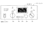
- FIG. 2 The configuration of the operation panel of the power amplifier 1 is shown in FIG. As shown in FIG. 2, a rectangular display 15 is provided at the upper center of the operation panel, and a seesaw-type power switch 31 is provided at the lower left side. On the right side of the switch 31, an Ach knob 30a for controlling the gain of the Ach sound signal and an Ach button 30b on which “A” is written are arranged vertically, and on the right side there are a menu key (Menu) 30c and a return key 30d. Arranged side by side.
- a rotary encoder with a push switch (hereinafter referred to as “encoder”) 30e on the right side, a Bch knob 30f for controlling the gain of the Bch sound signal on the right side, and a Bch button 30g on which “B” is written Placed in.
- a power lamp (POWER) and a warning lamp (ALERT) are arranged above the power switch 31, and a first lamp (PL1) is located above the Ach button 30b, and a second lamp (PL2) is located above the Bch button 30g. Be placed.
- the CPU 10 controls the Ach or Bch signal gain in the amplifier 1 in accordance with the amount of operation.
- FIG. 2 a home screen that mainly displays the current gains of Ach and Bch is displayed on the display 15.
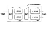
- FIG. 3 shows a block diagram of signal processing executed by the digital signal processing unit 21.
- the upper arrow is Ach
- the lower arrow is Bch.
- the two sound signals Ach and Bch from the waveform input unit 20 are supplied to a route control a block denoted by reference numeral 40.
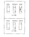
- the route control a one of DUAL / PARALLEL / SUM shown in FIG. 5A is connected according to the input configuration selected by the user.
- (a1) In DUAL the supplied Ach sound signal is output as an Ach sound signal
- the supplied Bch sound signal is output as a Bch sound signal.
- the supplied Ach sound signal is output as two sound signals Ach and Bch.
- the Ach and Bch sound signals output from the IN signal processing 41a and 41b are supplied to the route control b block denoted by reference numeral 42.
- the route control b one of the DUAL / PARALLEL / SINGLE connections shown in FIG. 5B is performed according to the input configuration selected by the user.
- the supplied Ach sound signal is output as an Ach sound signal
- the supplied Bch sound signal is output as a Bch sound signal.
- the supplied Ach sound signal is output as two sound signals Ach and Bch.
- b3 In SINGLE the supplied Ach sound signal is output as an Ach sound signal, and a silent sound signal is output as a Bch sound signal.
- FIG. 4 shows a block diagram of an example of signal processing of the SP signal processing 43a and 43b.
- the SP signal processing 43a, 43b is composed of a plurality of blocks including a cascaded crossover 50, a delay 51, an equalizer (EQ) 52, and a limiter 53.
- the parameter set used by each block of the SP signal processing unit is initialized based on an amplifier mode and an SP preset described later when the configuration data is applied.
- speakers 3 connected to the power amplifier 1 There are various types of speakers 3 connected to the power amplifier 1, and combinations thereof are also various. For example, there is a type that covers the entire audible band from low to high (FULL: full range system), a type that covers the low range in the audible band (SUB: subwoofer), and some of the wide range systems are low. There is a type (BI-AMP: bi-amplifier) that has a high-frequency speaker terminal and a high-frequency speaker terminal. These types of speakers are used in appropriate combinations according to the purpose of use. The input configuration and output configuration of the digital signal processing unit 21 are set according to the type and usage of the speaker 3 connected to the amplifier 1.
- FULL full range system
- SUV low range in the audible band
- BI-AMP bi-amplifier
- the [output configuration] is set by the user in accordance with the type of the one or two speakers 3 connected to the two output terminals of the Ach and Bch of the amplifier 1 and the usage form thereof. Then, according to the set [output configuration], the configuration of each of the two sound signals output by the amplifier 1 (which type of speaker sound signal) is determined. [Input configuration] is based on whether the input signals of a plurality of channels of the amplifier 1 are all used, only a part thereof, or whether the input signals are mixed when using all.
- an amplifier mode that defines what speaker 3 is connected to the power amplifier 1 and what signal is input is determined.
- the user first selects one output configuration, then selects an input configuration from the narrowed candidates, and based on the selected output configuration and input configuration.
- One amplifier mode is selected.
- a table of amplifier modes shown as a matrix of a plurality of output configurations and a plurality of input configurations as options is shown in FIG. This table has a row in which six output configurations are arranged and a column in which five input configurations are arranged. There are 30 selection frames (cells) in the table, and it is possible to set an amplifier mode in each selection frame.
- the amplifier mode which is not necessary is omitted, and the number of options is limited. For example, it is limited to 15 modes.
- One of the 15 amplifier modes is selected based on the output configuration and input configuration selected by the user.
- [FULL + FULL] is one type of speaker system (entire system) that covers the entire audible band at the two output terminals of Ach and Bch of amplifier 1 (total system). 2 units) Output configuration to be connected.
- This speaker system is not limited to 1 way but may be 2 way or 3 way. In this case, a sound signal in the entire audible band is supplied from the amplifier 1 to each speaker system.
- [SUB + SUB] is an output configuration in which one (sub-woofer) type speaker system (subwoofer) responsible for the low frequency range of the audible frequency is connected to the two output terminals of Ach and Bch of amplifier 1 one by one (total of two). is there.
- a low frequency sound signal is supplied from the amplifier 1 to each speaker system.
- [FULL + SUB] is an output configuration in which a FULL type speaker system is connected to the Ach output terminal of the amplifier 1 and a SUB type speaker system is connected to the Bch output terminal of the amplifier 1.
- the FULL type speaker system is supplied with a sound signal in which the low frequency band of the entire audible band is cut from the amplifier 1, and the SUB type speaker system is supplied with the low frequency sound signal. Is supplied.
- [BI-AMP] provides a bi-amp connectable speaker system (BI-AMP type), and the amplifier 1's Ach output terminal has a high-frequency speaker terminal for the BI-AMP type speaker system.
- This is an output configuration in which the low-frequency speaker terminal of the BI-AMP type speaker system is connected to the Bch output terminal of the amplifier 1 to drive the bi-amplifier.
- a low-frequency sound signal is supplied from the amplifier 1 to the high-frequency speaker terminal, and a low-frequency sound signal is supplied to the low-frequency speaker terminal. Is supplied.
- the [FULL (BOOST)] is connected to the Ach output terminal of the amplifier 1 by connecting one FULL type speaker system and using the total power that can be supplied by the analog power amplifier 23 for Ach power amplification.
- one loudspeaker system can be sounded louder than when two loudspeaker systems are connected (Boost operation) ).
- Boost operation a sound signal in the entire audible band is supplied to the Ach speaker system from the amplifier 1, and even if a speaker is connected to Bch, a silent sound signal is supplied to the speaker system. There is no sound.
- [SUB (BOOST)] is an output configuration in which a single SUB type speaker system is connected to the Ach output terminal of the amplifier 1 and the entire power is used for Ach power amplification to drive the speaker system strongly. is there. Similarly to the above, one loudspeaker system is sounded with a louder sound (Boost operation).
- [Input 2ch, mixed] is an input configuration for Boost operation, and the user inputs two independent sound signals to Ach and Bch of the amplifier 1, and the amplifier 1 inputs two inputs according to the corresponding configuration data.
- the input configuration is limited by the selected output configuration, and only that input configuration can be selected. For example, when the user selects [FULL + FULL], any input configuration of [input 2 ch, all stages 2 ch] [input 1 ch, all stages 2 ch] [input 2 ch, mixed] can be selected.
- the amplifier 1 selects one amplifier mode corresponding to the selected output configuration and input configuration, and sets configuration data corresponding to that mode. This is applied to the digital signal processing unit 21. For example, when [input 2ch, all stages 2ch] is selected, the mode 1 amplifier mode is selected.
- the route control a is set to (a1) DUAL, the Ach input signal is processed by the IN signal processing 41a, and the Bch input signal is processed by the IN signal processing 41b.
- the route control b is set to (b1) DUAL, the sound signal processed by the IN signal processing 41a is processed by the SP signal processing 43a, and the sound signal processed by the IN signal processing 41b is processed by the SP signal processing 43b. Is done.
- the settings of the route control a and the route control b are collectively indicated by “(a1, b1)” (FIG. 6).
- the parameter set of each block of the SP signal processing 43a and 43b is selected by the user according to the selected configuration data of mode 1 and the speaker 3 connected to the outputs of Ach and Bch.
- An initial setting value is set based on two SP presets corresponding to a FULL type two-speaker system (two [FULL]). In this mode 1, sound signals in all audible frequency bands that have been subjected to signal processing suitable for the two connected speakers 3 are output from the Ach and Bch of the amplifier 1.
- the memory 11 stores a plurality of configuration data corresponding to a plurality of amplifier modes.
- Each configuration data includes setting of route control a and b, speaker information designating each type of two speakers to be connected to Ach and Bch, and processing for determining the type of processing performed in each block of two SP signal processing It includes information and defines the path of the sound signal from the input section to the output section of the digital signal processing section 21 and the signal processing in that path. That is, by applying the configuration data according to the amplifier mode to the digital signal processing unit 21, the operation of the power amplifier 1 in the amplifier mode is realized.
- the speaker 3 connected to each output of the power amplifier 1 includes types such as FULL, SUB, and BI-AMP.
- the speaker 3 connected from the amplifier 1 has the frequency characteristics and phase characteristics of the speaker 3.
- the amplifier 1 applies a parameter set (multiple parameters) to each block of the SP signal processing 43a (43b) based on the SP preset selected by the user according to the speaker 3 connected thereto. Initial setting.
- the SP preset for each speaker is a parameter set prepared for the speaker by the manufacturer of the speaker, such as a parameter for flattening frequency characteristics, a parameter indicating delay time, a parameter indicating allowable input, The recommended cut-off frequency is included.
- the crossover 50 extracts a low-frequency sound signal or a high-frequency sound signal from the input sound signal based on the designated cutoff frequency according to the combination of the connected speakers 3.
- the configuration data of the selected amplifier mode specifies whether the high frequency or low frequency is extracted from the sound signal at the crossover 50 of each channel and output, or the sound signal is output as it is.
- the cutoff frequency is determined based on the SP preset selected by the user, and the Ach input signal is set to a low frequency at the cutoff frequency.
- the EQ 52 is an equalizer that adjusts the frequency characteristics of the sound signal, and is used here to flatten the frequency characteristics of the sound emitted from the connected speaker 3.
- the EQ 52 may be used to make a sound close to a desired frequency characteristic.
- the limiter 53 limits the level of the sound signal so that the power value of the output from the analog power amplifier 23 does not exceed the specified limit value.
- the limit value is set according to the power that can be output from the analog power amplifier 23 and the allowable input of the connected speaker 3. During BOOST operation, the limit value is relaxed to enable high output.
- the delay 51 delays and outputs the sound signal by a designated delay time. In general, it is used to align the phases of sound emitted from a plurality of speakers 3, but in the case of [FULL + SUB] and [BI-AMP] in particular, a high frequency speaker and a low frequency speaker are used. Used for phase alignment.
- the amplifier 1 selects the corresponding mode 2 and the configuration data of mode 2 is sent to the digital signal processing unit 21.
- (a2, 1b1) is set in the route controls a and b. That is, the route control a is set to (a2) PARALLEL, and the route control b is set to (b1) DUAL.
- the parameter sets of the SP signal processing 43a and 43b are initially set based on the configuration data of mode 2 and the two SP presets of the two FULL type speaker systems (two [FULL]) selected by the user. A set value is set. Sound signals in the entire audible band subjected to signal processing (flattening of frequency characteristics, phase control, power limitation, etc.) suitable for the two connected [FULL] type speakers 3 are sent from the Ach and Bch of the amplifier 1. Is output.
- the amplifier 1 selects the corresponding mode 3 and applies the configuration data of mode 3 to the digital signal processing unit 21.
- A3, b1 is set in the route control a and b, and the parameter set of the SP signal processing 43a and 43b is set to the configuration data of mode 3 and two SP presets of two [FULL] selected by the user. Initialized based on.
- the amplifier 1 selects the corresponding mode 8 and applies the configuration data of mode 8 to the digital signal processing unit 21.
- A1, b2 is set in the route control a, b
- the parameter set of the SP signal processing 43a, 43b is the mode 8 configuration data and two SP presets [SUB] and [FULL] selected by the user. Based on the above, an initial setting value is set.
- the SUB type speaker 3 ([SUB]) connected to the Ach of the amplifier 1 further receives a low-frequency sound signal extracted from the Ach input signal based on the cutoff frequency at the Ach crossover 50.
- the FULL type speaker 3 ([FULL]) output after being subjected to signal processing suitable for the speaker 3 and connected to the Bch of the amplifier 1 is connected to the Bch of the amplifier 1 based on the cutoff frequency at the Bch crossover 50.
- the high frequency sound signal extracted from the input signal is output after further signal processing suitable for the speaker 3 is performed.
- the cut-off frequencies for extracting the high frequency and low frequency sound signals should be matched.
- the amplifier 1 determines one cut-off frequency based on two SP presets [FULL] and [SUB] selected by the user.
- the recommended cutoff frequency of the [FULL] SP preset is lower than the recommended cutoff frequency of the [SUB] SP preset, increase the [FULL] cutoff frequency and increase the [SUB] (recommended) cutoff frequency. If the recommended cutoff frequency of the [FULL] SP preset is higher than the recommended cutoff frequency of the [SUB] SP preset, raise the [SUB] cutoff frequency and set the [FULL] (recommended) It is better to match the cutoff frequency.
- the amplifier 1 selects the corresponding mode 4 and applies the configuration data of mode 4 to the digital signal processing unit 21.
- A3, b1 is set in the route control a, b, and the SP signal processing 43a, 43b parameter set is applied with mode 4 configuration data and two SP presets of two [SUB] selected by the user. Is done.
- the [SUB] type speaker 3 connected to the Ach of the amplifier 1 outputs a low-frequency sound signal extracted from the Ach input signal based on the cutoff frequency suitable for the speaker 3 at the crossover 50.
- the [SUB] type speaker 3 connected to the Bch of the amplifier 1 outputs a low-frequency sound signal extracted from the Bch input signal based on the cutoff frequency suitable for the speaker 3 at the crossover 50. Is done. As the cutoff frequency of each channel, the recommended cutoff frequency included in the SP preset selected for that channel is used.
- the amplifier 1 selects the corresponding mode 10 and applies the configuration data of mode 10 to the digital signal processing unit 21.
- (A1, b2) is set in the route control a, b, and the parameter set of each block of the SP signal processing 43a, 43b is one of the configuration data of mode 10 and the [BI-AMP] type selected by the user.
- An initial setting value is set based on one SP preset corresponding to the speaker system.
- the low-frequency speaker terminal of the BI-AMP type speaker 3 connected to the Ach of the amplifier 1 outputs a low-frequency sound signal extracted based on the cutoff frequency by the Ach crossover 50, and the amplifier A high-frequency sound signal extracted based on the cut-off frequency at the Bch crossover 50 is output to the high-frequency speaker terminal of the speaker 3 connected to one Bch.
- the cut-off frequencies for extracting the high-frequency and low-frequency sound signals are the same (one), and are set to the two crossovers 50 as they are.
- the amplifier 1 selects the corresponding mode 11 and applies the configuration data of mode 11 to the digital signal processing unit 21.
- A3, b2 is set in the route control a and b, and the parameter set of the SP signal processing 43a and 43b is set to the configuration data of mode 11 and one SP preset of [BI-AMP] selected by the user. Based on this, an initial set value is set.
- the amplifier 1 selects mode 12 and applies the configuration data of mode 12 to the digital signal processing unit 21.
- (A1, b3) is set in the route control a, b, and the parameter set of the block of the SP signal processing 43a is the configuration data of mode 12 and the SP preset of the [FULL] type speaker system selected by the user. Based on this, an initial set value is set.
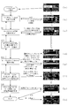
- FIG. 8 shows a flowchart of the configuration wizard process of the power amplifier 1 according to the present invention and a display screen displayed at each processing step.
- the CPU 10 causes the display 15 to display the [MENU] screen of ⁇ a >>.
- the [MENU] screen when the user turns the encoder 30e on the panel to move the cursor in the screen to [CONFIG WIZARD] and pushes the encoder 30e, the CPU 10 starts this configuration wizard process.
- the push switch of the encoder 30e functions as an enter key.
- the cursor moves on one screen and the parameter value changes on another screen.
- each selection screen described below displays a check column for each option, and the check column for the most recently selected option is checked.
- step S10 corresponds to the function of the first receiving unit that receives the selection of one output configuration from the plurality of output configurations from the user.
- step S11 the CPU 10 displays the [ROUTING] screen of ⁇ c >> on the display unit 15.
- the input configuration limited according to the output configuration selected in step S10 is displayed, and the user moves the cursor to temporarily select one of them. For example, if [FULL + FULL] is selected in step S10, [IN: 2CH ALL: 2CH] (input 2ch, all stages 2ch), [IN: 1CH ALL: 2CH] (input 1ch, all stages 2ch), [ Three input configurations are displayed: IN: 2CH MIX] (input 2ch, mixed).
- the user pushes the encoder 30e to confirm the selection of the input configuration.
- step S11 corresponds to the function of the second receiving unit that receives from the user the selection of one input configuration among the input configurations limited by the selected output configuration.
- step S11 corresponds to the function of the second receiving unit that receives from the user the selection of one input configuration among the input configurations limited by the selected output configuration.
- the icon of each amplifier mode displayed here includes a text of the input configuration and output configuration of the amplifier mode, and a schematic diagram of processing in the amplifier mode.
- ⁇ c >>, since [FULL + FULL] is selected and [IN: 2CH ALL: 2CH] is temporarily selected, the corresponding [Mode 1 (a1.b1)] icon is displayed.
- the CPU 10 selects one amplifier mode (for example, mode 1) corresponding to the selected output configuration and input configuration, and proceeds to step S13.
- This step S12 corresponds to the function of the selection unit that selects one amplifier mode from among a plurality of amplifier modes based on the selected output configuration and the selected input configuration.
- step S13 the CPU 10 first causes the display 15 to display the [SP ⁇ SERIES] screen of ⁇ d >>.
- the [SP SERIES] screen of ⁇ d >> displays the target channel, the type of speaker that should be connected to that channel in the selected amplifier mode, and the speaker system product that matches that type as selection candidates.
- the target channel is [A] and the speaker type [FULL], and [A], [CBR], including [FULL] type products as selection candidates 3 series of [Club IV] and [ ⁇ GENERIC>] and [ ⁇ FLAT>] indicating general products are displayed.
- the user moves the cursor to temporarily select any one of those series or general products.
- the desired series or general product is provisionally selected, the user pushes the encoder 30e to confirm the selection of the series or general product.
- the CPU 10 checks the corresponding rectangular check box and proceeds to the next process in step S13 ([NEXT]).
- ⁇ d >> the [CBR] series is selected. If the user presses the return key 30d during the above process, the CPU 10 returns to the previous process (S11) ([BACK]) and can execute the input configuration selection process again.
- the CPU 10 causes the display 15 to display the [SP MODEL] screen of ⁇ e >>.
- the target channel [A] the speaker type [FULL] of the target channel
- the products corresponding to the [FULL] type in the selected [CBR] series are displayed.
- the user moves the cursor to temporarily select one of these products.
- the user pushes the encoder 30e to confirm the selection of the product (SP preset).
- the CPU 10 checks the corresponding rectangular check box, and when the selected configuration data specifies the Bch speaker type in addition to Ach (mode 1 to mode 9), the next processing in step S13 If only the Ach speaker type is designated (mode 10 to mode 15), the process proceeds to step S14.
- the CPU 10 returns to the previous process ([BACK]) and executes the series selection process again.
- the Ach speaker type of the selected configuration data is [FULL]
- only [FULL] type products SP presets
- the Ach speaker type is [SUB]
- only [SUB] type products are displayed on the same screen as [BI-AMP]
- only [BI-AMP] type products are displayed as selection candidates.
- the CPU 10 displays a screen asking the user whether or not to select the product selected in Ach also in Bch. 15 is displayed. If the response is made when the user selects, the CPU 10 selects the same product (SP preset) as Ach in Bch, and proceeds to step S14.
- the CPU 10 selects one series from the user on the [SP SERIES] screen of Bch as in the case of Ach described above. Next, selection of one product (SP preset) is received from the user on the [SP MODEL] screen.
- the CPU 10 When the user presses the return key 30d during each selection process, the CPU 10 returns to the previous selection process ([BACK]) and executes the previous selection process again. Then, when the selection of the Ach and Bch SP presets is completed, the CPU 10 proceeds to step S14.
- step S14 the CPU 10 includes the setting of the route control a and b and the parameter set of the SP signal processing 43a and 43b based on the configuration data of the selected amplifier mode and the selected 1 or 2 SP preset. Determine one configuration plan (multiple parameter values). Then, the CPU 10 causes the display 15 to display the [CONFIRMATION] screen of ⁇ f >> including the determined setting plan. The user turns the encoder 30e, scrolls the setting plan in the [CONFIRMATION] screen, and confirms each parameter value. If there is no problem, the user pushes the encoder 30e and instructs application. As a result, the CPU 10 proceeds to step S15 ([APPLY]). If there is any problem, the user operates the return key 30d, and the CPU 10 returns to the previous process (S13) ([BACK]), and the Ach or Bch SP preset selection process performed immediately before. Run again.
- step S15 the CPU 10 sets each parameter value of the setting plan determined in step S14 as an initial value in a parameter set such as route control a and b, SP signal processing 43a and 43b, and performs signal processing thereof. Apply a configuration plan.
- the CPU 10 displays a [CONFIG WIZARD] screen including [EXECUTED!] On the display unit 15 to notify the user that the setting of the power amplifier 1 is completed. For example, when mode 1 is selected and [CBR12] is selected for chA and chB, the Ach of amplifier 1 outputs a sound signal that has been subjected to signal processing suitable for CBR12 on the Ach input signal and amplified in power.
- Steps S14 and S15 described above correspond to the function of the application unit that selects configuration data corresponding to the selected amplifier mode from the plurality of configuration data and applies the signal processing performed by the signal processing unit.
- the CPU 10 ends the configuration wizard process, and the CPU 10 causes the display 15 to display the home screen of ⁇ h >>.
- the Ach and Bch products for example, [CBR12]
- different products [SW115V]) are displayed for Ach and Bch.
- Each parameter value set based on the setting plan is not a fixed value and can be individually adjusted by a user on another screen (not shown).
- each block of the digital signal processing unit 21 performs signal processing corresponding to the selected amplifier mode (configuration data) and the selected product (SP preset). For example, in the SP signal processing 43 for a channel in which one [FULL] type product is selected regardless of the mode, a parameter set is set based on the SP preset corresponding to that product. Similarly, the SP preset of the [SUB] product is applied to the SP signal processing 43 of the channel for which a certain [SUB] product is selected. When any of modes 7 to 9 is selected and a [FULL] product and a [SUB] product are selected, the SP is based on the two SP presets of the [FULL] product and the [SUB] product. A cutoff frequency in the crossover 50 of the signal processing 43 is determined.
- the user can adjust the parameter values of the IN signal processing 41a and 41b and the SP signal processing 43a and 43b using the user interface of the amplifier 1. For example, when the user turns the Ach knob 30a, the CPU 10 changes the gain of Ach. Moreover, the edit screen of the crossover 50 can be entered, the cutoff frequency can be selected, and the value can be changed by the encoder 30e.
- the present invention can also be applied to acoustic devices other than 2ch, for example, acoustic devices such as 4ch and 8ch.
- acoustic devices such as 4ch and 8ch.
- two channels may be paired, and the method of the present invention may be applied to each pair, or a group may be formed by three or more channels and the method of the present invention may be applied to each group.
- the number of sound signal input units and output units may be the same as in the above-described embodiment, but is not limited thereto, and may be a different number.
- the power amplifier setting method of the present invention is not limited to the power amplifier, and is applied to various acoustic devices connected to the front stage of the power amplifier, such as a speaker processor and a stage box for extending the input / output of the digital mixer. it can.
- Ach is used, but Bch may be used.
- modes 7 to 11 the low frequency is processed by Ach and the high frequency is processed by Bch.
- the processing may be reversed.
- there are six output configuration options but it is not necessary to limit to six. For example, only three of [FULL + FULL], [SUB + SUB], and [FULL + SUB] in the table of FIG. 6 may be used.
- the input configuration options need not be limited to the embodiment. In the present invention, the number of modes to be selected may be smaller than the product of the number of output configurations and the number of input configurations.
- the output configuration and the input configuration limited according to the output configuration are presented to the user, the user is allowed to specify the output configuration and the input configuration, and the specified output configuration and input configuration are specified.
- the present invention is characterized in that a limited amplifier mode is presented to the user and one of the amplifier modes is selected. That is, the user first selects an output configuration (easy to understand), and then the user selects one input configuration from among the input configurations limited by the selected output configuration, and these are selected. Based on the output configuration and the input configuration, one amplifier mode is selected from the plurality of amplifier modes, and the configuration data corresponding to the selected amplifier mode is applied to the signal processing performed by the signal processing unit. First, the user selects an output configuration that is relatively easy, and then selects an input configuration from among the narrowed options, so that the setting according to the usage pattern of the speaker can be easily performed.
- the amplifier mode selected by the user includes information on what kind of speaker is connected to the power amplifier, so that SP presets that can be selected in the amplifier mode are narrowed down. That is, first, one piece of configuration data is selected from a plurality of pieces of configuration data in accordance with the user's selection operation. Next, a speaker corresponding to the selected configuration data is extracted from the plurality of speakers, and the user selects one speaker from the extracted speakers. Then, the selected configuration data and the preset corresponding to the selected speaker are applied to the signal processing performed by the signal processing unit.
- Each configuration data contains information on what type of speaker to connect, and by narrowing down the choices of the speaker based on that type, the user can easily make settings that match the usage pattern of the speaker. Can do.
Landscapes
- Engineering & Computer Science (AREA)
- Multimedia (AREA)
- Physics & Mathematics (AREA)
- Acoustics & Sound (AREA)
- Signal Processing (AREA)
- Health & Medical Sciences (AREA)
- General Health & Medical Sciences (AREA)
- Otolaryngology (AREA)
- Amplifiers (AREA)
- Circuit For Audible Band Transducer (AREA)
Abstract
まず、ユーザが1つの出力構成を選択すると(S10)、選択された出力構成に応じて、入力構成の選択肢が制限される。さらに、ユーザが、その1つの入力構成を選択すると(S11)、選択された出力構成および入力構成に応じた1つのアンプモードが選択される(S12)。選択されたアンプモードのコンフィグデータに基づいて、音信号の処理経路が決まり、ユーザの選択したSPプリセットと合わせて、信号処理部のパラメータが設定される(S14)。これにより、ユーザは、スピーカの使用形態に合わせた音響機器の設定を容易に行うことができる。
Description
この発明は、スピーカの使用形態に合わせた設定を容易に行うことができるパワーアンプ等の音響機器の設定方法、及び音響機器に関する。
従来の信号処理機能を有さないパワーアンプでは、スピーカを最適に鳴らすために、内部にイコライザやフィルタを備え、スピーカから放音される音の特性を均一にしたり、音作りするためのスピーカプロセッサを前段に接続する使い方もあった。
そのスピーカプロセッサの例を非特許文献1に示す。このスピーカプロセッサは、イコライザーやディレイ等、スピーカー調整用の各種機能のコンポーネントを備え、ユーザが各コンポーネントのパラメータを変更して、信号処理の効果を調整する。スピーカプロセッサを上手く調整すれば、種々のスピーカーに、最適なプロセッシングをかけることができる。
そのスピーカプロセッサの例を非特許文献1に示す。このスピーカプロセッサは、イコライザーやディレイ等、スピーカー調整用の各種機能のコンポーネントを備え、ユーザが各コンポーネントのパラメータを変更して、信号処理の効果を調整する。スピーカプロセッサを上手く調整すれば、種々のスピーカーに、最適なプロセッシングをかけることができる。
ヤマハ株式会社 SPEAKERPROCESSOR SP2060 取扱説明書[online], [平成28年 1月27日検索],インターネット<http://download.yamaha.com/api/asset/file?language=ja&site=countrysite-master.prod.wsys.yamaha.com&asset_id=47915>
スピーカシステムのタイプには、全可聴帯域をカバーする全域システム、可聴帯域中の低域だけを担当するサブウーファがある。また、全域システムの中には、低域スピーカと高域スピーカを備え、その各スピーカの専用の入力端子を備えた、バイアンプ接続可能なシステムがある。また、各スピーカシステムは、同じタイプのシステムであってもそのシステム特有の音特性を有している。例えば、出せる周波数帯域幅が異なっていたり、その帯域内の出力音圧レベルや許容入力電力が異なっていたりする。また、複数のスピーカシステムが組み合わされて使用される場合もある。ユーザは、スピーカプロセッサを用いて、パワーアンプの各チャンネル(ch)の出力信号を、そのchに接続されているスピーカシステムに適した特性に調整すべきである。また、ユーザは、スピーカの使用形態に応じて、スピーカプロセッサ内の信号経路等を適宜設定すべきである。
しかしながら、スピーカプロセッサに、使用形態やスピーカの特性に合わせて、信号経路や各コンポーネントのパラメータ値を設定することは、スキルの低いユーザや初心者には難しいという問題があった。
そこで、本発明は、スキルの低いユーザであってもスピーカの使用形態に合わせた設定を容易に行えるパワーアンプ等の音響機器の設定方法を提供することを目的としている。
上記目的を達成するために、本発明のパワーアンプの設定方法は、n及びmをそれぞれ1以上の整数とする時、n入力部およびm出力部に接続された信号処理部を備えた音響機器の設定方法であって、複数のコンフィグデータを用意する第1ステップと、複数の出力構成の中からの1の出力構成の選択を、ユーザから受け取る第2ステップと、選択された出力構成で制限された入力構成の中からの1の入力構成の選択を、ユーザから受け取る第3ステップと、選択された出力構成と、選択された入力構成とに基づいて、複数のアンプモードの中から1つのアンプモードを選択する第4ステップと、選択されたアンプモードに応じたコンフィグデータを選択して、前記信号処理部が行う信号処理に適用する第5ステップとを備えることを最も主要な特徴としている。
本発明は、上記のように方法として実施する他、システム、装置等、任意の態様で実施することができる。
本発明は、上記のように方法として実施する他、システム、装置等、任意の態様で実施することができる。
上述した本発明によれば、スキルの低いユーザであっても、パワーアンプ等の音響機器をスピーカの使用形態に合わせて容易に設定することができる。
以下、本発明を実施するための形態を図面に基づいて具体的に説明する。
まず、図1に、本発明の設定方法の1つの実施形態であるパワーアンプ1の構成を示すブロック図を示す。
図1のパワーアンプ1は、基本的にAch(A channel)とBch(B channel)との2ch構成であり、バス24で接続された、CPU(Central Processing Unit)10、フラッシュメモリ11、RAM(Random Access Memory)12、その他I/O13、操作子14、表示器15と、波形入力部20、デジタル信号処理部21、D/A・A/D部22、アナログ電力増幅部23とを備えている。上記したデジタル信号処理部21は、1乃至複数のDSP(Digital Signal Processor)で構成される。
まず、図1に、本発明の設定方法の1つの実施形態であるパワーアンプ1の構成を示すブロック図を示す。
図1のパワーアンプ1は、基本的にAch(A channel)とBch(B channel)との2ch構成であり、バス24で接続された、CPU(Central Processing Unit)10、フラッシュメモリ11、RAM(Random Access Memory)12、その他I/O13、操作子14、表示器15と、波形入力部20、デジタル信号処理部21、D/A・A/D部22、アナログ電力増幅部23とを備えている。上記したデジタル信号処理部21は、1乃至複数のDSP(Digital Signal Processor)で構成される。
このうちCPU10は、パワーアンプ1の動作を統括制御する制御手段であり、メモリ11に記憶された制御プログラムを実行することにより、操作子14の操作に応じて、パラメータを編集したり、表示器15を制御したり、デジタル信号処理部21の信号処理を制御する。フラッシュメモリ11は、書き換え可能な不揮発メモリであり、前記制御プログラムに加え、複数のコンフィグデータ、複数のスピーカに対応する複数のSPプリセット等を記憶する。複数のコンフィグデータの1つが、後述するアンプモードで特定され、各コンフィグデータは、入力部から出力部までの音信号の経路と、その経路における信号処理とを規定する。RAM12は、CPU10が各種のデータを書き込み及び読み出しする揮発性メモリであり、CPU10のワークメモリ、アンプ1の現在の動作を制御する複数パラメータを記憶するカレントメモリとして使用される。その他I/O13は、種々の外部機器を接続して通信を行うためのインタフェースである。その他I/O13における通信に用いる規格は、イーサネット(商標)、USB(Universal Serial Bus)等、任意のものを採用することができ、有線無線も問わない。表示器15は、CPU10の制御に従って種々の情報を表示する表示手段であり、例えば液晶パネル(LCD)や発光ダイオード(LED)によって構成される。
音信号の入力部から出力部までの経路の構成について説明すると、波形入力部20は、アンプ1の2つの入力端子を介して、外部ソース2からアナログのAchとBchの2つの音信号(入力信号)を受け取り、それぞれ、デジタルの音信号に変換してデジタル信号処理部21へ供給する。デジタル信号処理部21は、そのデジタルの2つの音信号に対し、クロスオーバー処理、ディレイ処理、イコライザ処理、リミッタ処理、ダイナミクス処理などの信号処理を施し、処理済みの2つの音信号をD/A・A/D部22へ出力する。D/A・A/D部22は、デジタルの2つの各音信号をアナログの音信号に変換し、アナログ電力増幅部23に供給する。アナログ電力増幅部23は、アナログの2つの各音信号を電力増幅し、電力増幅されたAchとBchの音信号(出力信号)をスピーカ端子に接続された1乃至2のスピーカ3へ出力する。
パワーアンプ1の操作パネルの構成を図2に示す。図2に示すように、操作パネル中央の上側に矩形状の表示器15が、左側下部にシーソー型の電源スイッチ31が設けられる。スイッチ31の右側にAchの音信号のゲインを制御するAchつまみ30aと「A」が表記されたAchボタン30bとが縦に配置され、その右側にメニューキー(Menu)30cとリターンキー30dが横に並んで配置される。さらに、その右側にプッシュスイッチ付きのロータリーエンコーダー(以下、「エンコーダー」という)30e、その右側にBchの音信号のゲインを制御するBchつまみ30fと「B」が表記されたBchボタン30gとが縦に配置される。また、電源スイッチ31の上側に電源ランプ(POWER)と警告ランプ(ALERT)とが配置され、Achボタン30bの上側に第1ランプ(PL1)、Bchボタン30gの上側に第2ランプ(PL2)が配置される。ユーザが、Achつまみ30aあるいはBchつまみ30fを操作すると、その操作量に応じて、アンプ1におけるAchあるいはBchの信号ゲインが、CPU10により制御される。図2では、表示器15に、AchとBchの現在のゲインを主に表示するホーム画面が表示されている。
次に、図3にデジタル信号処理部21の実行する信号処理のブロック図を示す。上段の矢印がAchであり、下段の矢印がBchである。
この図に示すように、波形入力部20からのAchとBchの2つの音信号は、符号40で示すルート制御aのブロックに供給される。ルート制御aでは、ユーザにより選択された入力構成に応じて、図5の(a)に示されるDUAL/PARALLEL/SUMの何れかの接続を行う。(a1)DUALでは、供給されたAchの音信号をAchの音信号として出力し、供給されたBchの音信号をBchの音信号として出力する。(a2)PARALLELでは、供給されたAchの音信号をAchとBchの2つの音信号として出力する。(a3)SUMでは、供給されたAchとBchの2つの音信号を混合して、その和の音信号をAchとBchの2つの音信号として出力する。ルート制御aからのAchとBchの2つの音信号は、それぞれ入力側処理を行う2つのIN信号処理41a,41bへ供給され、各chのIN信号処理41a,41bでは、直列接続された複数ブロック(マルチバンドコンプ、ディレイ等)により、その各chに接続されたスピーカとは無関係に、共通の信号処理を供給された音信号に施す。IN信号処理部の各ブロックが信号処理に用いるパラメータセットは、後述するコンフィグデータの適用時に、所定値に初期設定される。
この図に示すように、波形入力部20からのAchとBchの2つの音信号は、符号40で示すルート制御aのブロックに供給される。ルート制御aでは、ユーザにより選択された入力構成に応じて、図5の(a)に示されるDUAL/PARALLEL/SUMの何れかの接続を行う。(a1)DUALでは、供給されたAchの音信号をAchの音信号として出力し、供給されたBchの音信号をBchの音信号として出力する。(a2)PARALLELでは、供給されたAchの音信号をAchとBchの2つの音信号として出力する。(a3)SUMでは、供給されたAchとBchの2つの音信号を混合して、その和の音信号をAchとBchの2つの音信号として出力する。ルート制御aからのAchとBchの2つの音信号は、それぞれ入力側処理を行う2つのIN信号処理41a,41bへ供給され、各chのIN信号処理41a,41bでは、直列接続された複数ブロック(マルチバンドコンプ、ディレイ等)により、その各chに接続されたスピーカとは無関係に、共通の信号処理を供給された音信号に施す。IN信号処理部の各ブロックが信号処理に用いるパラメータセットは、後述するコンフィグデータの適用時に、所定値に初期設定される。
また、IN信号処理41a,41bから出力されたAchとBchの音信号は、符号42で示すルート制御bのブロックに供給される。ルート制御bでは、ユーザにより選択された入力構成に応じて、図5の(b)に示されるDUAL/PARALLEL/SINGLEの何れかの接続を行う。(b1)DUALでは、供給されたAchの音信号をAchの音信号として出力し、供給されたBchの音信号をBchの音信号として出力する。(b2)PARALLELでは、供給されたAchの音信号をAchとBchの2つの音信号として出力する。(b3)SINGLEでは、供給されたAchの音信号をAchの音信号として出力し、無音の音信号をBchの音信号として出力する。ルート制御bからのAchとBchの2つの音信号は、それぞれ各chに接続されたスピーカ3に応じた信号処理を行う2つのSP信号処理43a,43bへ供給される。SP信号処理43a,43bの信号処理の一例のブロック図を図4に示す。この図に示すように、SP信号処理43a,43bでは、縦続接続されたクロスオーバー50、ディレイ51、イコライザ(EQ)52、リミッタ53の複数ブロックにより構成される。SP信号処理部の各ブロックが用いるパラメータセットは、コンフィグデータの適用時に、後述するアンプモードとSPプリセットに基づいて初期設定される。
パワーアンプ1に接続されるスピーカ3には種々のタイプがあり、その組み合わせも様々になる。例えば、低域から高域までの全可聴帯域をカバーするタイプ(FULL:全域システム)、可聴帯域中の低域を担当するタイプ(SUB:サブウーファ)があり、さらに全域システムの中には、低域スピーカ用端子と高域スピーカ用端子を備えバイアンプ接続が可能なタイプ(BI-AMP:バイアンプ)がある。これらのタイプのスピーカは、使用目的に応じて適宜組み合わせて使用される。アンプ1に接続されるスピーカ3のタイプや使用形態に応じて、デジタル信号処理部21の入力構成および出力構成が設定される。[出力構成]は、アンプ1のAchとBchの2出力端子に接続する1乃至2のスピーカ3のタイプや、その使用形態に応じてユーザが設定する。そして、設定された[出力構成]に応じて、アンプ1が出力する2つの各音信号の構成(どのタイプのスピーカ用の音信号か)が決まる。また、[入力構成]は、アンプ1の複数chの入力信号を全部使うか、一部だけを使うか、および、全部を使う場合に、入力信号を混合して使うか否かに基づいてユーザが設定し、設定された[入力構成]に応じて、アンプ1が受け取る音信号の構成(使う入力信号の数)と、デジタル信号処理部21における各処理ブロックが受け取る音信号の構成(どのchの入力信号、又は混合信号か)が決まる。
設定された出力構成および入力構成に基づいて、パワーアンプ1にどのようなスピーカ3を接続して、どのような信号を入力するか規定するアンプモードが決まる。本発明にかかるパワーアンプの設定方法では、ユーザが、まず1つの出力構成を選択し、次に、絞られた候補の中から入力構成を選択し、選択された出力構成と入力構成とに基づいて1つのアンプモードを選択することを特徴としている。
選択肢となる複数の出力構成と複数の入力構成のマトリクスとして示されるアンプモードのテーブルを図6に示す。このテーブルは、6つの出力構成が並べられた行と、5つの入力構成が並べられた列を有する。テーブルの全ての選択枠(セル)は30あり、それぞれの選択枠にアンプモードを設定可能ではあるが、本発明においては必要性の薄いアンプモードを省略して、選択肢を限られたモード数、例えば15モードに限定していることを特徴としている。この15のアンプモードの1つが、ユーザが選択した出力構成と入力構成とに基づいて選択される。出力構成の各選択肢について説明すると、[FULL+FULL]は、アンプ1のAchとBchの2出力端子に、全可聴帯域をカバーするタイプ(FULLタイプ)のスピーカシステム(全域システム)を1台ずつ(計2台)接続する出力構成である。このスピーカシステムは、1wayに限らず、2wayや3wayでもよい。この場合、各スピーカシステムには、アンプ1から全可聴帯域の音信号が供給される。
選択肢となる複数の出力構成と複数の入力構成のマトリクスとして示されるアンプモードのテーブルを図6に示す。このテーブルは、6つの出力構成が並べられた行と、5つの入力構成が並べられた列を有する。テーブルの全ての選択枠(セル)は30あり、それぞれの選択枠にアンプモードを設定可能ではあるが、本発明においては必要性の薄いアンプモードを省略して、選択肢を限られたモード数、例えば15モードに限定していることを特徴としている。この15のアンプモードの1つが、ユーザが選択した出力構成と入力構成とに基づいて選択される。出力構成の各選択肢について説明すると、[FULL+FULL]は、アンプ1のAchとBchの2出力端子に、全可聴帯域をカバーするタイプ(FULLタイプ)のスピーカシステム(全域システム)を1台ずつ(計2台)接続する出力構成である。このスピーカシステムは、1wayに限らず、2wayや3wayでもよい。この場合、各スピーカシステムには、アンプ1から全可聴帯域の音信号が供給される。
[SUB+SUB]は、アンプ1のAchとBchの2出力端子に、可聴周波数の低域を担当するタイプ(SUBタイプ)のスピーカシステム(サブウーファ)を1台ずつ(計2台)接続する出力構成である。対応するコンフィグデータを適用すると、各スピーカシステムには、アンプ1から低域の音信号が供給される。
[FULL+SUB]は、アンプ1のAchの出力端子にFULLタイプのスピーカシステムを、アンプ1のBchの出力端子にSUBタイプのスピーカシステムをそれぞれ接続する出力構成である。対応するコンフィグデータを適用すると、FULLタイプのスピーカシステムには、アンプ1から全可聴帯域のうち低域がカットされた音信号が供給され、SUBタイプのスピーカシステムには、その低域の音信号が供給される。
[FULL+SUB]は、アンプ1のAchの出力端子にFULLタイプのスピーカシステムを、アンプ1のBchの出力端子にSUBタイプのスピーカシステムをそれぞれ接続する出力構成である。対応するコンフィグデータを適用すると、FULLタイプのスピーカシステムには、アンプ1から全可聴帯域のうち低域がカットされた音信号が供給され、SUBタイプのスピーカシステムには、その低域の音信号が供給される。
[BI-AMP]は、バイアンプ接続可能なタイプ(BI-AMPタイプ)のスピーカシステムを用意し、アンプ1のAchの出力端子に、そのBI-AMPタイプのスピーカシステムの高域スピーカ用端子を、アンプ1のBchの出力端子に、そのBI-AMPタイプのスピーカシステムの低域スピーカ用端子をそれぞれ接続してバイアンプ駆動する出力構成である。対応するコンフィグデータを適用すると、高域スピーカ用端子には、アンプ1から全可聴帯域のうち低域がカットされた音信号が供給され、低域スピーカ用端子には、その低域の音信号が供給される。
[FULL(BOOST)]は、アンプ1のAchの出力端子に、FULLタイプのスピーカシステムを1台接続し、アナログ電力増幅部23で供給可能な全電力をAchの電力増幅に使うことにより、その1台のスピーカシステムをより強力に駆動する出力構成である。アンプ1のBchの出力を無音信号にし、Bch出力の保護回路の制限を緩めることで、スピーカシステムを2台接続しているときに比べ、1台のスピーカシステムをより大きな音で鳴らせる(Boost動作)。対応するコンフィグデータを適用すると、Achのスピーカシステムには、アンプ1から全可聴帯域の音信号が供給され、仮に、Bchにスピーカを接続したとしても、そのスピーカシステムには無音の音信号が供給され音は鳴らない。
[SUB(BOOST)]は、アンプ1のAchの出力端子に、SUBタイプのスピーカシステムを1台接続し、全電力をAchの電力増幅に用いて、そのスピーカシステムを強力に駆動する出力構成である。上記と同様に、1台のスピーカシステムを、より大きな音で鳴らせる(Boost動作)。
[FULL(BOOST)]は、アンプ1のAchの出力端子に、FULLタイプのスピーカシステムを1台接続し、アナログ電力増幅部23で供給可能な全電力をAchの電力増幅に使うことにより、その1台のスピーカシステムをより強力に駆動する出力構成である。アンプ1のBchの出力を無音信号にし、Bch出力の保護回路の制限を緩めることで、スピーカシステムを2台接続しているときに比べ、1台のスピーカシステムをより大きな音で鳴らせる(Boost動作)。対応するコンフィグデータを適用すると、Achのスピーカシステムには、アンプ1から全可聴帯域の音信号が供給され、仮に、Bchにスピーカを接続したとしても、そのスピーカシステムには無音の音信号が供給され音は鳴らない。
[SUB(BOOST)]は、アンプ1のAchの出力端子に、SUBタイプのスピーカシステムを1台接続し、全電力をAchの電力増幅に用いて、そのスピーカシステムを強力に駆動する出力構成である。上記と同様に、1台のスピーカシステムを、より大きな音で鳴らせる(Boost動作)。
次に、ユーザが指定する入力構成について説明すると、[入力2ch、全段2ch]は、ユーザがアンプ1のAchとBchに独立した2つの音信号を入力し、対応するコンフィグデータにより、アンプ1は、Achの入力信号をIN信号処理41aとSP信号処理43aで処理するとともに、Bchの入力信号をIN信号処理41bとSP信号処理43bで処理する入力構成である。
[入力1ch、全段2ch]は、ユーザが、パワーアンプ1のAchに1つの音信号を入力し、対応するコンフィグデータにより、アンプ1は、Achの入力信号を、IN信号処理41aとSP信号処理43a、および、IN信号処理41bとSP信号処理43bで並列に処理する入力構成である。
[入力1ch、後段2ch]は、ユーザが、アンプ1のAchに1つの音信号を入力し、対応するコンフィグデータにより、アンプ1は、Achの入力信号をIN信号処理41aで処理した後、その処理後の音信号を、SP信号処理43a,43bで並列に処理する入力構成である。
[入力1ch、全段1ch]は、Boost動作用の入力構成であり、ユーザは、アンプ1のAchに1つの音信号を入力し、対応するコンフィグデータにより、アンプ1は、Achの入力信号を、IN信号処理41aとSP信号処理43aで処理する入力構成である。
[入力2ch、混合]は、Boost動作用の入力構成であり、ユーザは、アンプ1のAchとBchに独立した2つの音信号を入力し、対応するコンフィグデータにより、アンプ1は、2つの入力信号を混合し、上述した[入力1ch、**(「*」はワイルドカード)]の入力構成と同様の態様で、その和の音信号に、IN信号処理とSP信号処理とを施す入力構成である。この場合、[出力構成]に応じて、IN信号処理とSP信号処理の経路が一意に決まる。
[入力1ch、全段2ch]は、ユーザが、パワーアンプ1のAchに1つの音信号を入力し、対応するコンフィグデータにより、アンプ1は、Achの入力信号を、IN信号処理41aとSP信号処理43a、および、IN信号処理41bとSP信号処理43bで並列に処理する入力構成である。
[入力1ch、後段2ch]は、ユーザが、アンプ1のAchに1つの音信号を入力し、対応するコンフィグデータにより、アンプ1は、Achの入力信号をIN信号処理41aで処理した後、その処理後の音信号を、SP信号処理43a,43bで並列に処理する入力構成である。
[入力1ch、全段1ch]は、Boost動作用の入力構成であり、ユーザは、アンプ1のAchに1つの音信号を入力し、対応するコンフィグデータにより、アンプ1は、Achの入力信号を、IN信号処理41aとSP信号処理43aで処理する入力構成である。
[入力2ch、混合]は、Boost動作用の入力構成であり、ユーザは、アンプ1のAchとBchに独立した2つの音信号を入力し、対応するコンフィグデータにより、アンプ1は、2つの入力信号を混合し、上述した[入力1ch、**(「*」はワイルドカード)]の入力構成と同様の態様で、その和の音信号に、IN信号処理とSP信号処理とを施す入力構成である。この場合、[出力構成]に応じて、IN信号処理とSP信号処理の経路が一意に決まる。
図6のアンプモードのテーブルを参照すると、ユーザにより、まず出力構成のいずれかが選択されると、選択された出力構成で入力構成が制限され、その入力構成だけが選択可能となる。例えば、ユーザが[FULL+FULL]を選択すると、[入力2ch、全段2ch][入力1ch、全段2ch][入力2ch、混合]の何れかの入力構成を選択可能となる。次に、ユーザが、選択可能な入力構成の1つを選択すると、アンプ1は、選択された出力構成と入力構成に応じた1つのアンプモードを選択して、そのモードに対応するコンフィグデータをデジタル信号処理部21に適用する。例えば、[入力2ch、全段2ch]を選択すると、モード1のアンプモードが選択される。モード1のアンプ1では、ルート制御aが(a1)DUALに設定され、Achの入力信号はIN信号処理41aで処理され、Bchの入力信号はIN信号処理41bで処理される。そして、ルート制御bが(b1)DUALに設定され、IN信号処理41aで処理された音信号はSP信号処理43aで処理され、IN信号処理41bで処理された音信号はSP信号処理43bで処理される。これらルート制御aとルート制御bの設定をまとめて「(a1, b1)」で示す(図6)。このコンフィグデータの適用時に、SP信号処理43a,43bの各ブロックのパラメータセットには、選択されたモード1のコンフィグデータと、AchとBchの出力に接続されたスピーカ3に応じてユーザが選択したFULLタイプの2スピーカシステム(2つの[FULL])に対応する2つのSPプリセットとに基づいて初期設定値が設定される。このモード1では、接続された2つのスピーカ3に適した信号処理が施された全可聴周波数帯域の音信号が、アンプ1のAch、Bchから出力される。
メモリ11には、複数のアンプモードに対応する複数のコンフィグデータが記憶されている。各コンフィグデータは、ルート制御a,bの設定、AchとBchに接続すべき2つのスピーカの各タイプを指定するスピーカ情報、および、2つのSP信号処理の各ブロックで行う処理の種類を決める処理情報を含み、デジタル信号処理部21の入力部から出力部までの音信号の経路と、その経路における信号処理とを規定する。すなわち、アンプモードに応じたコンフィグデータをデジタル信号処理部21に適用することにより、そのアンプモードにおけるパワーアンプ1の動作が実現される。
ところで、パワーアンプ1の各出力に接続されるスピーカ3には、FULL、SUB、BI-AMPなどのタイプがあり、アンプ1から接続されたスピーカ3に、そのスピーカ3の周波数特性や位相特性などに応じて調整され、かつ、そのスピーカ3の許容入力に応じて電力制限された音信号を供給することにより、スピーカ3が持つ性能を十分に引き出すことができる。このため、アンプモードの選択時には、アンプ1が、SP信号処理43a(43b)の各ブロックに、接続されたスピーカ3に応じてユーザが選択したSPプリセットに基づいて、パラメータセット(複数パラメータ)を初期設定する。なお、各スピーカのSPプリセットは、そのスピーカのメーカー等が、そのスピーカ用に用意したパラメータセットであり、周波数特性をフラットにするパラメータや、遅延時間を示すパラメータや、許容入力を示すパラメータや、推奨するカットオフ周波数等が含まれている。
ここで、図4の各SP信号処理の各ブロックの信号処理を説明する。クロスオーバー50は、接続されたスピーカ3の組み合わせに応じて、入力された音信号から、指定されたカットオフ周波数に基づいて、低域の音信号または高域の音信号を取り出す。各chのクロスオーバー50で音信号から高域と低域の何れを取り出して出力するか、或いは、音信号をそのまま出力するかは、選択されたアンプモードのコンフィグデータが指定する。例えば、ユーザにより[FULL+SUB]または[BI-AMP]の出力構成が指定された場合に、ユーザの選択したSPプリセットに基づいてカットオフ周波数を決め、そのカットオフ周波数でAchの入力信号を低域と高域の音信号に分けてそれぞれAchとBchとから出力する。また、EQ52は、音信号の周波数特性を調整するイコライザであり、ここでは、接続されたスピーカ3から放音される音の周波数特性を平坦化するのに用いられる。このEQ52は、所望の周波数特性に近づけて音作りするのに用いてもよい。リミッタ53は、アナログ電力増幅部23からの出力の電力値が、指定された制限値を超えないように、音信号のレベルを制限する。その制限値は、アナログ電力増幅部23の出力可能電力や、接続されたスピーカ3の許容入力に応じて設定される。BOOST動作時にはその制限値を緩めて、大出力を可能とする。また、ディレイ51は、音信号を、指定された遅延時間だけ遅延して出力する。一般に、複数のスピーカ3から放音される音の位相を相互に揃えるのに用いられるが、特に、[FULL+SUB]や[BI-AMP]の場合には、高域用スピーカと低域用スピーカの位相合わせに用いられる。
ここで、図4の各SP信号処理の各ブロックの信号処理を説明する。クロスオーバー50は、接続されたスピーカ3の組み合わせに応じて、入力された音信号から、指定されたカットオフ周波数に基づいて、低域の音信号または高域の音信号を取り出す。各chのクロスオーバー50で音信号から高域と低域の何れを取り出して出力するか、或いは、音信号をそのまま出力するかは、選択されたアンプモードのコンフィグデータが指定する。例えば、ユーザにより[FULL+SUB]または[BI-AMP]の出力構成が指定された場合に、ユーザの選択したSPプリセットに基づいてカットオフ周波数を決め、そのカットオフ周波数でAchの入力信号を低域と高域の音信号に分けてそれぞれAchとBchとから出力する。また、EQ52は、音信号の周波数特性を調整するイコライザであり、ここでは、接続されたスピーカ3から放音される音の周波数特性を平坦化するのに用いられる。このEQ52は、所望の周波数特性に近づけて音作りするのに用いてもよい。リミッタ53は、アナログ電力増幅部23からの出力の電力値が、指定された制限値を超えないように、音信号のレベルを制限する。その制限値は、アナログ電力増幅部23の出力可能電力や、接続されたスピーカ3の許容入力に応じて設定される。BOOST動作時にはその制限値を緩めて、大出力を可能とする。また、ディレイ51は、音信号を、指定された遅延時間だけ遅延して出力する。一般に、複数のスピーカ3から放音される音の位相を相互に揃えるのに用いられるが、特に、[FULL+SUB]や[BI-AMP]の場合には、高域用スピーカと低域用スピーカの位相合わせに用いられる。
例えば、ユーザが[FULL+FULL]の出力構成と、[入力1ch、全段2ch]の入力構成を選択すると、アンプ1は、対応するモード2を選択し、モード2のコンフィグデータをデジタル信号処理部21に適用する。これにより、ルート制御a,bには(a2, b1)が設定される。すなわち、ルート制御aが(a2)PARALLELに設定され、ルート制御bが(b1)DUALに設定される。このとき、SP信号処理43a,43bのパラメータセットには、モード2のコンフィグデータと、ユーザが選択したFULLタイプの2つのスピーカシステム(2つの[FULL])の2つのSPプリセットとに基づいて初期設定値が設定される。接続された2つの[FULL]タイプのスピーカ3に適した信号処理(周波数特性の平坦化、位相制御、電力制限など)が施された全可聴帯域の音信号が、アンプ1のAch、Bchから出力される。
ユーザが[FULL+FULL]と[入力2ch、混合]を選択すると、アンプ1は、対応するモード3を選択し、モード3のコンフィグデータをデジタル信号処理部21に適用する。ルート制御a,bには(a3, b1)が設定され、SP信号処理43a,43bのパラメータセットは、モード3のコンフィグデータと、ユーザが選択した2つの[FULL]の2つのSPプリセットとに基づいて初期設定される。
ユーザが[FULL+SUB]の出力構成と[入力1ch、後段2ch]の入力構成を選択すると、アンプ1は、対応するモード8を選択し、モード8のコンフィグデータをデジタル信号処理部21に適用する。ルート制御a,bには(a1, b2)が設定され、SP信号処理43a,43bのパラメータセットは、モード8のコンフィグデータと、ユーザが選択した[SUB]と[FULL]の2つのSPプリセットとに基づいて初期設定値が設定される。アンプ1のAchに接続されたSUBタイプのスピーカ3([SUB])には、Achのクロスオーバー50でカットオフ周波数に基づいてAchの入力信号から抽出された低域の音信号が、更にそのスピーカ3に適した信号処理を施された後に出力され、アンプ1のBchに接続されたFULLタイプのスピーカ3([FULL])には、Bchのクロスオーバー50でカットオフ周波数に基づいてAchの入力信号から抽出された高域の音信号が、更にそのスピーカ3に適した信号処理を施された後に出力される。ここで、高域と低域の音信号の抽出用のカットオフ周波数は一致させるべきである。アンプ1は、ユーザにより選択された[FULL]と[SUB]の2つのSPプリセットに基づき1つのカットオフ周波数を決める。例えば、[FULL]のSPプリセットの推奨カットオフ周波数が[SUB]のSPプリセットの推奨カットオフ周波数より低い場合は、[FULL]のカットオフ周波数を上げて[SUB]の(推奨)カットオフ周波数に合わせ、また、[FULL]のSPプリセットの推奨カットオフ周波数が[SUB]のSPプリセットの推奨カットオフ周波数より高い場合は、[SUB]のカットオフ周波数を上げて[FULL]の(推奨)カットオフ周波数に合わせるようにするのがよい。
ユーザが[SUB+SUB]の出力構成と[入力2ch、全段2ch]の入力構成を選択すると、アンプ1は、対応するモード4を選択し、モード4のコンフィグデータをデジタル信号処理部21に適用する。ルート制御a,bには(a3, b1)が設定され、SP信号処理43a,43bのパラメータセットは、モード4のコンフィグデータと、ユーザが選択した2つの[SUB]の2つのSPプリセットが適用される。アンプ1のAchに接続された[SUB]タイプのスピーカ3には、クロスオーバー50でそのスピーカ3に適したカットオフ周波数に基づいてAchの入力信号から抽出された低域の音信号が出力され、アンプ1のBchに接続された[SUB]タイプのスピーカ3には、クロスオーバー50でそのスピーカ3に適したカットオフ周波数に基づいてBchの入力信号から抽出された低域の音信号が出力される。各chのカットオフ周波数には、そのchで選択されたSPプリセットに含まれる推奨カットオフ周波数が用いられる。
ユーザが[BI-AMP]の出力構成と[入力1ch、後段2ch]の入力構成を選択すると、アンプ1は、対応するモード10を選択し、モード10のコンフィグデータをデジタル信号処理部21に適用する。ルート制御a,bには(a1, b2)が設定され、SP信号処理43a,43bの各ブロックのパラメータセットは、モード10のコンフィグデータと、ユーザが選択した[BI-AMP]タイプの1つのスピーカシステムに対応する1つのSPプリセットに基づいて初期設定値が設定される。アンプ1のAchに接続された、BI-AMPタイプのスピーカ3の低域スピーカ用端子には、Achのクロスオーバー50でカットオフ周波数に基づいて抽出された低域の音信号が出力され、アンプ1のBchに接続されたそのスピーカ3の高域スピーカ用端子には、Bchのクロスオーバー50でカットオフ周波数に基づいて抽出された高域の音信号が出力される。[BI-AMP]のSPプリセットでは、高域と低域の音信号の抽出用のカットオフ周波数は同じ(1つ)であり、そのまま2つのクロスオーバー50に設定される。
ユーザが[BI-AMP]と[入力2ch、混合]を選択すると、アンプ1は、対応するモード11を選択し、モード11のコンフィグデータをデジタル信号処理部21に適用する。ルート制御a,bには(a3, b2)が設定され、SP信号処理43a,43bのパラメータセットは、モード11のコンフィグデータと、ユーザが選択した[BI-AMP]の1つのSPプリセットとに基づいて初期設定値が設定される。
ユーザが[FULL(BOOST)]の出力構成と[入力1ch、全段1ch]の入力構成を選択すると、アンプ1は、モード12を選択し、モード12のコンフィグデータをデジタル信号処理部21に適用する。ルート制御a,bには(a1,b3)が設定され、SP信号処理43aのブロックのパラメータセットは、モード12のコンフィグデータと、ユーザが選択した[FULL]タイプのスピーカシステムのSPプリセットとに基づいて初期設定値が設定される。
図8に、本発明に係るパワーアンプ1のコンフィグウィザード処理のフローチャートと、その各処理ステップで表示される表示画面を示す。
ユーザが、パネルのメニューキー(Menu)30cを押すと、CPU10は、表示器15に、《a》の[MENU]画面を表示させる。この[MENU]画面で、ユーザがパネルのエンコーダー30eを回して画面中のカーソルを[CONFIG WIZARD]に移動し、エンコーダー30eをプッシュすると、CPU10は、このコンフィグウィザード処理を起動する。このように、エンコーダー30eのプッシュスイッチはエンターキーとして機能する。また、エンコーダ30eの回転により、ある画面ではカーソルが移動し、別の画面ではパラメータ値が変化する。ある文字にアイコンがあるとき、その文字は背景白の黒文字で表示され、ある文字にアイコンがないとき、その文字は背景黒の白抜き文字で表示される。また、これから説明する各選択画面には、選択肢毎のチェック欄が表示されており、直近に選択された選択肢のチェック欄にチェックが入っている。コンフィグウィザード処理が開始されると、ステップS10で、CPU10は、《b》の[SP TYPE]画面を表示器15に表示する。[SP TYPE]画面では、6つの出力構成の1つを、ユーザがエンコーダー30eを回すことで、スクロールしつつカーソルを動かして仮選択できる。この画面内の右部には、仮選択されている出力構成に応じたアイコン(図7(a))が表示される。所望の出力構成が選択されたら、ユーザは、エンコーダー30eをプッシュし、出力構成の選択を確定する。CPU10は、その出力構成の矩形のチェック欄にチェックを入れ、ステップS11に進む([NEXT])。このステップS10が、複数の出力構成の中からの1の出力構成の選択をユーザから受け取る第1受取部の機能と対応する。
ユーザが、パネルのメニューキー(Menu)30cを押すと、CPU10は、表示器15に、《a》の[MENU]画面を表示させる。この[MENU]画面で、ユーザがパネルのエンコーダー30eを回して画面中のカーソルを[CONFIG WIZARD]に移動し、エンコーダー30eをプッシュすると、CPU10は、このコンフィグウィザード処理を起動する。このように、エンコーダー30eのプッシュスイッチはエンターキーとして機能する。また、エンコーダ30eの回転により、ある画面ではカーソルが移動し、別の画面ではパラメータ値が変化する。ある文字にアイコンがあるとき、その文字は背景白の黒文字で表示され、ある文字にアイコンがないとき、その文字は背景黒の白抜き文字で表示される。また、これから説明する各選択画面には、選択肢毎のチェック欄が表示されており、直近に選択された選択肢のチェック欄にチェックが入っている。コンフィグウィザード処理が開始されると、ステップS10で、CPU10は、《b》の[SP TYPE]画面を表示器15に表示する。[SP TYPE]画面では、6つの出力構成の1つを、ユーザがエンコーダー30eを回すことで、スクロールしつつカーソルを動かして仮選択できる。この画面内の右部には、仮選択されている出力構成に応じたアイコン(図7(a))が表示される。所望の出力構成が選択されたら、ユーザは、エンコーダー30eをプッシュし、出力構成の選択を確定する。CPU10は、その出力構成の矩形のチェック欄にチェックを入れ、ステップS11に進む([NEXT])。このステップS10が、複数の出力構成の中からの1の出力構成の選択をユーザから受け取る第1受取部の機能と対応する。
ステップS11で、CPU10は、《c》の[ROUTING]画面を表示器15に表示させる。この[ROUTING]画面には、ステップS10で選択された出力構成に応じて制限された入力構成が表示され、ユーザはカーソルを動かしてその何れか1つを仮選択する。例えば、ステップS10で[FULL+FULL]が選択された場合は、[IN:2CH ALL:2CH](入力2ch、全段2ch)、[IN:1CH ALL:2CH](入力1ch、全段2ch)、[IN:2CH MIX](入力2ch、混合)の3つの入力構成が表示される。所望の入力構成が選択されたら、ユーザは、エンコーダー30eをプッシュし、入力構成の選択を確定する。この画面内の右部には、選択された出力構成と仮選択されている入力構成とに対応する1つのアンプモードのアイコン(図7(b))が表示される。CPU10は、その入力構成の矩形のチェック欄にチェックを入れ、ステップS12に進む([NEXT])。このステップS11が、選択された出力構成で制限された入力構成の中からの1の入力構成の選択を、ユーザから受け取る第2受取部の機能と対応する。なお、ステップS11の処理中において、ユーザがリターンキー30dを押すと、CPU10は、前の処理(S10)に戻り([BACK])、出力構成の選択処理を再度実行する。
ここで表示される各アンプモードのアイコン(図7(b))には、そのアンプモードの入力構成と出力構成のテキストと、そのアンプモードにおける処理の概要図が含まれる。《c》の例では、[FULL+FULL]が選択され、[IN:2CH ALL:2CH]が仮選択されているので、対応する[モード1 (a1.b1)]のアイコンが表示されている。ステップS12で、CPU10は、選択された出力構成と入力構成とに対応する1つのアンプモード(例えば、モード1)を選択し、ステップS13に進む。このステップS12が、選択された出力構成と、選択された入力構成とに基づいて、複数のアンプモードの中から1つのアンプモードを選択する選択部の機能と対応する。
ステップS13で、CPU10は、まず、《d》の[SP SERIES]画面を表示器15に表示させる。《d》の[SP SERIES]画面には、対象とするchと、選択されたアンプモードでそのchに接続すべきスピーカのタイプと、そのタイプに適合するスピーカシステムの製品が選択候補として表示される。メモリ11には、各製品に対応して1つのSPプリセットが記憶されているので、ここでの1の製品の選択は、対応する1のSPプリセットの選択と看做せる。また、この画面で1つのタイプに適合する全製品を表示すると、数が多すぎてユーザが選びきれないので、ここでは、まず、製品のシリーズ、次に、個別の製品の2段階で、ユーザが1つの製品を選択するようになっている。《d》に示すAchの[SP SERIES]画面の例では、対象ch[A]、スピーカタイプ[FULL]であり、選択候補として、[FULL]タイプの製品を含む[A]、[CBR]、[Club V]の3シリーズと、一般製品を示す[<GENERIC>]および[<FLAT>]とが表示されている。ここで、ユーザは、カーソルを動かして、それらシリーズ乃至一般製品の何れか1つを仮選択する。所望のシリーズ乃至一般製品が仮選択されたら、ユーザは、エンコーダー30eをプッシュし、そのシリーズ乃至一般製品の選択を確定する。CPU10は、対応する矩形のチェック欄にチェックを入れ、ステップS13内の次の処理に進む([NEXT])。《d》では、[CBR]のシリーズが選択されている。なお、上記処理中において、ユーザがリターンキー30dを押すと、CPU10は、前の処理(S11)に戻り([BACK])、入力構成の選択処理を再度実行できるようになる。
ステップS13内の次の処理で、CPU10は、《e》の[SP MODEL]画面を表示器15に表示させる。《e》の[SP MODEL]画面には、対象ch[A]、その対象chのスピーカタイプ[FULL]と、選択された[CBR]シリーズで[FULL]タイプに該当する製品が表示されている。ここで、ユーザは、カーソルを動かして、それら製品のうちの何れか1つを仮選択する。所望の製品(SPプリセット)が選択されたら、ユーザは、エンコーダー30eをプッシュして、製品(SPプリセット)の選択を確定する。CPU10は、対応する矩形のチェック欄にチェックを入れ、選択されたコンフィグデータがAchに加えてBchのスピーカタイプも指定している場合は(モード1~モード9)、ステップS13内の次の処理へ進み、Achのスピーカタイプだけを指定している場合は(モード10~モード15)、ステップS14に進む。なお、上記処理中において、ユーザがリターンキー30dを押すと、CPU10は、前の処理に戻り([BACK])、シリーズの選択処理を再度実行する。選択されたコンフィグデータのAchのスピーカタイプが[FULL]の場合、Achの[SP MODEL]画面においては、[FULL]タイプの製品(SPプリセット)のみが選択候補として表示される。また、Achのスピーカタイプが[SUB]の場合、[SUB]タイプの製品のみが、[BI-AMP]の場合、[BI-AMP]タイプの製品のみが、それぞれ選択候補として同画面に表示される。
図示していないが、ステップS13内の次の処理で、BchのスピーカタイプがAchと同じ場合、CPU10は、Achで選択された製品をBchでも選択するか否か、ユーザに尋ねる画面を表示器15に表示する。ここで、ユーザが選択すると応答した場合は、CPU10は、BchでもAchと同じ製品(SPプリセット)を選択し、ステップS14に進む。ここで、ユーザが選択しないと応答した場合、又は、BchのスピーカタイプがAchと異なる場合は、CPU10は、上述したAchの場合と同様に、Bchの[SP SERIES]画面でユーザから1つのシリーズの選択を受け付け、次いで、[SP MODEL]画面でユーザから1つの製品(SPプリセット)の選択を受け付ける。その各選択処理中において、ユーザがリターンキー30dを押すと、CPU10は、直前の選択処理に戻り([BACK])、直前の選択処理を再度実行する。そして、AchとBchのSPプリセットの選択が終了すると、CPU10は、ステップS14に進む。
図示していないが、ステップS13内の次の処理で、BchのスピーカタイプがAchと同じ場合、CPU10は、Achで選択された製品をBchでも選択するか否か、ユーザに尋ねる画面を表示器15に表示する。ここで、ユーザが選択すると応答した場合は、CPU10は、BchでもAchと同じ製品(SPプリセット)を選択し、ステップS14に進む。ここで、ユーザが選択しないと応答した場合、又は、BchのスピーカタイプがAchと異なる場合は、CPU10は、上述したAchの場合と同様に、Bchの[SP SERIES]画面でユーザから1つのシリーズの選択を受け付け、次いで、[SP MODEL]画面でユーザから1つの製品(SPプリセット)の選択を受け付ける。その各選択処理中において、ユーザがリターンキー30dを押すと、CPU10は、直前の選択処理に戻り([BACK])、直前の選択処理を再度実行する。そして、AchとBchのSPプリセットの選択が終了すると、CPU10は、ステップS14に進む。
ステップS14で、CPU10は、選択されたアンプモードのコンフィグデータと、選択された1又は2のSPプリセットとに基づき、ルート制御a,bの設定とSP信号処理43a,43bのパラメータセットを含む1つの設定プラン(複数パラメータ値)を決定する。そして、CPU10は、決定した設定プランを含む《f》の[CONFIRMATION]画面を表示器15に表示させる。ユーザは、エンコーダー30eを回して[CONFIRMATION]画面中の設定プランをスクロールし、その各パラメータ値を確認する。問題なければ、ユーザは、エンコーダー30eをプッシュし、適用を指示する。これにより、CPU10は、ステップS15に進む([APPLY])。また、何か問題があれば、ユーザは、リターンキー30dを操作し、CPU10は、前の処理(S13)に戻って([BACK])、直前に行ったAch又はBchのSPプリセットの選択処理を再度実行する。
ステップS15で、CPU10は、ステップS14で決定された設定プランの各パラメータ値を、ルート制御a,b、SP信号処理43a,43b等のパラメータセットに初期値として設定して、それらの信号処理に設定プランを適用する。パラメータ値の設定が完了すると、CPU10は、[EXECUTED!]を含む[CONFIG WIZARD]画面を表示器15に表示させ、パワーアンプ1の設定が終了したことをユーザに知らせる。例えば、モード1が選択され、chAとchBで[CBR12]が選択された場合は、アンプ1のAchからは、Achの入力信号にCBR12に適した信号処理を施して電力増幅した音信号が出力され、アンプ1のBchからは、Bchの入力信号にCBR12に適した信号処理を施して電力増幅した音信号が出力される。以上のステップS14及びS15が、複数のコンフィグデータの中から、選択されたアンプモードに応じたコンフィグデータを選択して、前記信号処理部が行う信号処理に適用する適用部の機能と対応する。
ここで、ユーザが、エンコーダー30eをプッシュする([OK])と、CPU10は、コンフィグウィザード処理を終了し、CPU10は、《h》のホーム画面を表示器15に表示させる。このホーム画面には、AchとBchの現在のゲインとともに、直近のコンフィグウィザード処理で選択されたAchおよびBchの製品(例えば[CBR12])が表示される。なお、このコンフィグウィザード処理の実行前の図2のホーム画面では、Ach、Bchに別の製品([SW115V])が表示されていた。なお、設定プランに基づき設定された各パラメータ値は、固定値ではなく、図示しない別の画面においてユーザが個別に調整できる。
ここで、ユーザが、エンコーダー30eをプッシュする([OK])と、CPU10は、コンフィグウィザード処理を終了し、CPU10は、《h》のホーム画面を表示器15に表示させる。このホーム画面には、AchとBchの現在のゲインとともに、直近のコンフィグウィザード処理で選択されたAchおよびBchの製品(例えば[CBR12])が表示される。なお、このコンフィグウィザード処理の実行前の図2のホーム画面では、Ach、Bchに別の製品([SW115V])が表示されていた。なお、設定プランに基づき設定された各パラメータ値は、固定値ではなく、図示しない別の画面においてユーザが個別に調整できる。
コンフィグウィザード処理における設定プランの適用により、デジタル信号処理部21の各ブロックは、選択されたアンプモード(コンフィグデータ)、および、選択された製品(SPプリセット)に対応する信号処理を行う。例えば、モードを問わず、[FULL]タイプの1製品が選択されたchのSP信号処理43では、その製品に対応するSPプリセットに基づいてパラメータセットが設定される。同様に、ある[SUB]製品が選択されたchのSP信号処理43には、その[SUB]製品のSPプリセットが適用される。モード7~9の何れかが選択され、ある[FULL]製品とある[SUB]製品が選択された場合は、その[FULL]製品とその[SUB]製品の2つのSPプリセットに基づいて、SP信号処理43のクロスオーバー50におけるカットオフ周波数が決定される。
ユーザは、アンプ1のユーザインターフェースを使用して、IN信号処理41a,41bおよびSP信号処理43a,43bのパラメータの値を調整できる。例えば、ユーザがAchつまみ30aを回すと、CPU10は、Achのゲインを変える。また、クロスオーバー50の編集画面に入り、カットオフ周波数を選択して、エンコーダー30eでその値を変更できる。
以上説明した本発明にかかる実施形態は、2chのパワーアンプであったが、本発明は2ch以外の音響機器、例えば、4ch、8ch等の音響機器にも適用できる。その場合、2chずつをペアにして、そのペア毎に本発明の方法を適用してもよいし、3ch以上でグループを形成して、そのグループ毎に本発明の方法を適用してもよい。また、音信号の入力部と出力部の数は、上述の実施形態のように同数であってもよいが、これに限定されることはなく、異なる数であってもよい。
また、本発明のパワーアンプの設定方法は、パワーアンプに限らず、パワーアンプの前段に接続される種々の音響機器、例えば、スピーカプロセッサや、デジタルミキサの入出力を拡張するステージボックスなどに適用できる。また、一方のchだけ信号処理する場合、Achを使用していたが、Bchを使用してもよい。また、モード7~11では、低域をAchで、高域をBchで処理していたが、逆にしてもよい。
以上の説明では、出力構成の選択肢は6つだったが、6つに限定する必要は無い。例えば、図6の表の[FULL+FULL]、[SUB+SUB]、[FULL+SUB]の3つだけでも良い。また、入力構成の選択肢も、実施例に限定する必要は無い。本発明では、選択されるモード数が、出力構成の数と入力構成の数との積より少ない数にできればよい。
また、本発明のパワーアンプの設定方法は、パワーアンプに限らず、パワーアンプの前段に接続される種々の音響機器、例えば、スピーカプロセッサや、デジタルミキサの入出力を拡張するステージボックスなどに適用できる。また、一方のchだけ信号処理する場合、Achを使用していたが、Bchを使用してもよい。また、モード7~11では、低域をAchで、高域をBchで処理していたが、逆にしてもよい。
以上の説明では、出力構成の選択肢は6つだったが、6つに限定する必要は無い。例えば、図6の表の[FULL+FULL]、[SUB+SUB]、[FULL+SUB]の3つだけでも良い。また、入力構成の選択肢も、実施例に限定する必要は無い。本発明では、選択されるモード数が、出力構成の数と入力構成の数との積より少ない数にできればよい。
以上説明した本発明にかかる実施形態は、出力構成と、出力構成に応じて制限された入力構成をユーザに提示して、ユーザに出力構成および入力構成を指定させ、指定した出力構成および入力構成に応じて制限されたアンプモードをユーザに提示して、その1つのアンプモードを選択させることを特徴としている。
すなわち、まず、ユーザが(理解の容易な)出力構成を選択し、次に、ユーザが選択された出力構成で制限された入力構成の中からの1の入力構成を選択して、それら選択された出力構成と入力構成とに基づいて、複数のアンプモードの中から1つのアンプモードが選択され、選択されたアンプモードに応じたコンフィグデータが、信号処理部が行う信号処理に適用される。ユーザが、まず、比較的容易な出力構成の選択を行ったあと、狭められた選択肢の中から入力構成を選択することで、スピーカの使用形態に合わせた設定を容易に行うことができる。
すなわち、まず、ユーザが(理解の容易な)出力構成を選択し、次に、ユーザが選択された出力構成で制限された入力構成の中からの1の入力構成を選択して、それら選択された出力構成と入力構成とに基づいて、複数のアンプモードの中から1つのアンプモードが選択され、選択されたアンプモードに応じたコンフィグデータが、信号処理部が行う信号処理に適用される。ユーザが、まず、比較的容易な出力構成の選択を行ったあと、狭められた選択肢の中から入力構成を選択することで、スピーカの使用形態に合わせた設定を容易に行うことができる。
また、ユーザが選択したアンプモードには、パワーアンプにどういう特性のスピーカを接続するかの情報が入っているので、そのアンプモードで選択できるSPプリセットが絞られるようになることを特徴としている。
すなわち、まず、ユーザの選択操作に応じて、複数のコンフィグデータの中から1つのコンフィグデータを選択する。次に、選択されたコンフィグデータに対応するスピーカを複数のスピーカの中から抽出し、ユーザが、その抽出されたスピーカの中から1のスピーカを選択する。そして、選択されたコンフィグデータと、選択されたスピーカに対応するプリセットとが、信号処理部が行う信号処理に適用される。各コンフィグデータには、どういうタイプのスピーカを接続するかの情報が入っており、そのタイプに基づいてスピーカの選択肢を絞り込むことで、ユーザは、スピーカの使用形態に合わせた設定を容易に行うことができる。
すなわち、まず、ユーザの選択操作に応じて、複数のコンフィグデータの中から1つのコンフィグデータを選択する。次に、選択されたコンフィグデータに対応するスピーカを複数のスピーカの中から抽出し、ユーザが、その抽出されたスピーカの中から1のスピーカを選択する。そして、選択されたコンフィグデータと、選択されたスピーカに対応するプリセットとが、信号処理部が行う信号処理に適用される。各コンフィグデータには、どういうタイプのスピーカを接続するかの情報が入っており、そのタイプに基づいてスピーカの選択肢を絞り込むことで、ユーザは、スピーカの使用形態に合わせた設定を容易に行うことができる。
1 パワーアンプ、2 外部ソース、3 スピーカ、10 CPU、11 フラッシュメモリ、12 RAM、13 その他I/O、14 操作子、15 表示器、20 波形入力部、21 デジタル信号処理部、22 D/A・A/D部、23 アナログ電力増幅部、24 バス、30a Achつまみ、30b Achボタン、30c メニューキー、30d リターンキー、30e ロータリーエンコーダー、30f Bchつまみ、30g Bchボタン、31 電源スイッチ、40 ルート制御a、41a,41b 信号処理、42 ルート制御b、43a,43b 信号処理、50 クロスオーバー、51 ディレイ、52 EQ、53 リミッタ
Claims (14)
- n及びmをそれぞれ1以上の整数とする時、n入力部およびm出力部に接続された信号処理部を備えた音響機器の設定方法であって、
複数のコンフィグデータを用意する第1ステップと、
複数の出力構成の中からの1の出力構成の選択を、ユーザから受け取る第2ステップと、
選択された出力構成で制限された入力構成の中からの1の入力構成の選択を、ユーザから受け取る第3ステップと、
選択された出力構成と、選択された入力構成とに基づいて、複数のアンプモードの中から1つのアンプモードを選択する第4ステップと、
選択されたアンプモードに応じたコンフィグデータを選択して、前記信号処理部が行う信号処理に適用する第5ステップと、
を備えることを特徴とする音響機器の設定方法。 - 前記複数のコンフィグデータは、それぞれ、n入力部からm出力部までの音信号の経路と、その経路における信号処理とを規定することを特徴とする請求項1に記載の音響機器の設定方法。
- 前記複数の出力構成は、それぞれ、m出力部に接続される1乃至複数のスピーカのタイプを指定することを特徴とする請求項1または2に記載の音響機器の設定方法。
- 前記複数のコンフィグデータは、前記タイプとして、全域システム、または、低域システムを指定することを特徴とする請求項1ないし3のいずれかに記載の音響機器の設定方法。
- 前記複数のコンフィグデータには、前記タイプとしてバイアンプを指定するコンフィグデータが含まれることを特徴とする請求項4に記載の音響機器の設定方法。
- 前記複数の入力構成は、それぞれ、n入力部が受け取るn信号の一部だけを使用するか、全部を使用するかを規定することを特徴とする請求項1ないし5のいずれかに記載の音響機器の設定方法。
- 前記複数の入力構成は、n入力が受け取るn信号を、ペア毎に混合して処理するか、混合せずに処理するかを規定することを特徴とする請求項1ないし6のいずれかに記載の音響機器の設定方法。
- 複数のスピーカに対応する複数のプリセットを用意する第6ステップと、
選択されたコンフィグデータに対応するスピーカを、前記複数のスピーカの中から抽出する第7ステップと、
抽出されたスピーカの中からの1のスピーカの選択を、ユーザから受け取る第8ステップと
を、さらに備え、前記第5ステップでは、選択されたスピーカに対応するプリセットを、前記信号処理部が行う信号処理に適用することを特徴とする請求項1ないし7のいずれかに記載の音響機器の設定方法。 - 前記複数のコンフィグデータは、それぞれ、前記m出力部に接続されるmスピーカのタイプを指定し、
前記第7ステップでは、前記複数のスピーカの中から、前記コンフィグデータにより指定されたタイプのスピーカを抽出することを特徴とする請求項8に記載の音響機器の設定方法。 - 前記複数のコンフィグデータは、それぞれ、前記信号処理部における、前記n入力部から前記m出力部までの音信号の経路と、その経路における処理ブロックの音信号処理とを規定することを特徴とする請求項9に記載の音響機器の設定方法。
- 前記複数のコンフィグデータは、前記処理ブロックのクロスオーバの動作を指定し、
前記クロスオーバのカットオフ周波数は、前記第8ステップで選択されたスピーカに対応するプリセットに基づいて決定されることを特徴とする請求項10に記載の音響機器の設定方法。 - 前記第8ステップで選択されたスピーカに対応するプリセットは、当該スピーカの周波数特性を平坦化するイコライザのパラメータを含むことを特徴とする請求項8ないし11のいずれかに記載の音響機器の設定方法。
- 前記第8ステップで選択されたスピーカに対応するプリセットは、当該スピーカの許容入力を示すパラメータを含むことを特徴とする請求項8ないし12のいずれかに記載の音響機器の設定方法。
- n及びmをそれぞれ1以上の整数とする時、n入力部およびm出力部に接続された信号処理部を備えた音響機器であって、
複数の出力構成の中からの1の出力構成の選択を、ユーザから受け取る第1受取部と、
選択された出力構成で制限された入力構成の中からの1の入力構成の選択を、ユーザから受け取る第2受取部と、
選択された出力構成と、選択された入力構成とに基づいて、複数のアンプモードの中から1つのアンプモードを選択する選択部と、
複数のコンフィグデータの中から、選択されたアンプモードに応じたコンフィグデータを選択して、前記信号処理部が行う信号処理に適用する適用部と、
を備えることを特徴とする音響機器。
Priority Applications (2)
| Application Number | Priority Date | Filing Date | Title |
|---|---|---|---|
| CN201780017556.3A CN109155897B (zh) | 2016-03-23 | 2017-03-23 | 音响设备的设定方法及音响设备 |
| US16/137,634 US10505508B2 (en) | 2016-03-23 | 2018-09-21 | Configuration method of audio equipment and audio equipment |
Applications Claiming Priority (4)
| Application Number | Priority Date | Filing Date | Title |
|---|---|---|---|
| JP2016058000A JP6665617B2 (ja) | 2016-03-23 | 2016-03-23 | 音響機器の設定方法 |
| JP2016058001A JP6728832B2 (ja) | 2016-03-23 | 2016-03-23 | 音響機器の設定方法 |
| JP2016-058001 | 2016-03-23 | ||
| JP2016-058000 | 2016-03-23 |
Related Child Applications (1)
| Application Number | Title | Priority Date | Filing Date |
|---|---|---|---|
| US16/137,634 Continuation US10505508B2 (en) | 2016-03-23 | 2018-09-21 | Configuration method of audio equipment and audio equipment |
Publications (1)
| Publication Number | Publication Date |
|---|---|
| WO2017164286A1 true WO2017164286A1 (ja) | 2017-09-28 |
Family
ID=59900305
Family Applications (1)
| Application Number | Title | Priority Date | Filing Date |
|---|---|---|---|
| PCT/JP2017/011645 Ceased WO2017164286A1 (ja) | 2016-03-23 | 2017-03-23 | 音響機器の設定方法及び音響機器 |
Country Status (3)
| Country | Link |
|---|---|
| US (1) | US10505508B2 (ja) |
| CN (1) | CN109155897B (ja) |
| WO (1) | WO2017164286A1 (ja) |
Families Citing this family (4)
| Publication number | Priority date | Publication date | Assignee | Title |
|---|---|---|---|---|
| US10609505B1 (en) * | 2018-01-06 | 2020-03-31 | Stillwater Designs And Audio, Inc. | Method and apparatus for automated tuning of vehicle sound system |
| US11483030B2 (en) * | 2020-04-03 | 2022-10-25 | Bose Corporation | Power distribution system for 3 phase balanced loads |
| JP7452270B2 (ja) * | 2020-06-10 | 2024-03-19 | ヤマハ株式会社 | 車載音響システム、及びこの車載音響システムを備える車両 |
| US12003932B2 (en) * | 2022-02-08 | 2024-06-04 | Dell Products, L.P. | Speaker system for slim profile display devices |
Citations (3)
| Publication number | Priority date | Publication date | Assignee | Title |
|---|---|---|---|---|
| JPH10313223A (ja) * | 1997-03-10 | 1998-11-24 | Matsushita Electric Ind Co Ltd | Avアンプ |
| JP2006237928A (ja) * | 2005-02-24 | 2006-09-07 | Matsushita Electric Ind Co Ltd | パラレル駆動バイアンプ切換回路 |
| JP2007116643A (ja) * | 2005-10-18 | 2007-05-10 | Audio Design:Kk | オーディオ信号処理装置 |
Family Cites Families (13)
| Publication number | Priority date | Publication date | Assignee | Title |
|---|---|---|---|---|
| US6674864B1 (en) * | 1997-12-23 | 2004-01-06 | Ati Technologies | Adaptive speaker compensation system for a multimedia computer system |
| US6775385B1 (en) * | 1999-09-21 | 2004-08-10 | James Loudspeaker, Llc | Loudspeaker frequency distribution and adjusting circuit |
| US20030021433A1 (en) * | 2001-07-30 | 2003-01-30 | Lee Kyung Lak | Speaker configuration and signal processor for stereo sound reproduction for vehicle and vehicle having the same |
| WO2009086627A1 (en) * | 2008-01-04 | 2009-07-16 | Eleven Engineering Incorporated | Audio system with bonded-peripheral driven mixing and effects |
| CN103501165B (zh) * | 2010-01-07 | 2018-01-05 | 塔特公司 | 利用eq进行基于压缩器的动态低音增强 |
| CN102215287B (zh) * | 2010-04-12 | 2014-07-02 | 中兴通讯股份有限公司 | 切换通讯模块音频通道的方法及装置 |
| JP2012227589A (ja) * | 2011-04-15 | 2012-11-15 | Clarion Co Ltd | デジタルスピーカーシステム |
| WO2015065125A1 (ko) * | 2013-10-31 | 2015-05-07 | 엘지전자(주) | 전자 기기 및 전자 기기의 제어 방법 |
| US9319792B1 (en) * | 2014-03-17 | 2016-04-19 | Amazon Technologies, Inc. | Audio capture and remote output |
| CN106465031B (zh) * | 2014-06-17 | 2019-10-18 | 夏普株式会社 | 音频装置、电视接收机以及声音信号调整方法 |
| US9337795B2 (en) * | 2014-09-09 | 2016-05-10 | Cirrus Logic, Inc. | Systems and methods for gain calibration of an audio signal path |
| US9351077B1 (en) * | 2014-12-11 | 2016-05-24 | L-3 Communications Integrated Systems Lp | Systems and methods for independent and control-isolated audio processing (ICIAP) |
| US9800357B2 (en) * | 2015-04-08 | 2017-10-24 | John Donald Tillman | Modular platform for creation and manipulation of audio and musical signals |
-
2017
- 2017-03-23 WO PCT/JP2017/011645 patent/WO2017164286A1/ja not_active Ceased
- 2017-03-23 CN CN201780017556.3A patent/CN109155897B/zh active Active
-
2018
- 2018-09-21 US US16/137,634 patent/US10505508B2/en active Active
Patent Citations (3)
| Publication number | Priority date | Publication date | Assignee | Title |
|---|---|---|---|---|
| JPH10313223A (ja) * | 1997-03-10 | 1998-11-24 | Matsushita Electric Ind Co Ltd | Avアンプ |
| JP2006237928A (ja) * | 2005-02-24 | 2006-09-07 | Matsushita Electric Ind Co Ltd | パラレル駆動バイアンプ切換回路 |
| JP2007116643A (ja) * | 2005-10-18 | 2007-05-10 | Audio Design:Kk | オーディオ信号処理装置 |
Also Published As
| Publication number | Publication date |
|---|---|
| CN109155897B (zh) | 2021-03-23 |
| US20190028076A1 (en) | 2019-01-24 |
| US10505508B2 (en) | 2019-12-10 |
| CN109155897A (zh) | 2019-01-04 |
Similar Documents
| Publication | Publication Date | Title |
|---|---|---|
| US9549260B2 (en) | Headphones for stereo tactile vibration, and related systems and methods | |
| JP6904012B2 (ja) | 音信号処理装置の制御方法、音信号処理装置及びプログラム | |
| WO2017164286A1 (ja) | 音響機器の設定方法及び音響機器 | |
| TWI613920B (zh) | 等化助聽器 | |
| US9479864B2 (en) | Effect applying apparatus and effect applying method | |
| US10356519B2 (en) | Audio monitor signal interception device | |
| JP6665617B2 (ja) | 音響機器の設定方法 | |
| JP6728832B2 (ja) | 音響機器の設定方法 | |
| US20240348221A1 (en) | Personal stage monitoring system with personal mixing | |
| JP2011024169A (ja) | ミキシングコンソール | |
| JP4582107B2 (ja) | 音響機器 | |
| JP4626626B2 (ja) | 音響機器 | |
| US10354631B2 (en) | Sound signal processing method and sound signal processing apparatus | |
| EP2369766A2 (en) | Mixer | |
| JP5251731B2 (ja) | ミキシングコンソールおよびプログラム | |
| KR101821396B1 (ko) | 음성 인식을 통한 오디오 믹서의 조정 시스템 | |
| JP2011024114A (ja) | デジタルミキサ | |
| JP2018117245A (ja) | 音処理装置及び方法 | |
| JP5870653B2 (ja) | レベル調整装置、およびレベル調整のためのプログラム | |
| US11653132B2 (en) | Audio signal processing method and audio signal processing apparatus | |
| JP5002994B2 (ja) | 処理系統図表示装置およびプログラム | |
| JP2017076907A (ja) | 音信号処理装置 | |
| US20140376725A1 (en) | Sound enhancement for powered speakers | |
| CN117041800A (zh) | 一种动态调整耳机喇叭频响的方法、耳机及存储介质 | |
| JP5418357B2 (ja) | デジタルミキサおよびプログラム |
Legal Events
| Date | Code | Title | Description |
|---|---|---|---|
| NENP | Non-entry into the national phase |
Ref country code: DE |
|
| 121 | Ep: the epo has been informed by wipo that ep was designated in this application |
Ref document number: 17770326 Country of ref document: EP Kind code of ref document: A1 |
|
| 122 | Ep: pct application non-entry in european phase |
Ref document number: 17770326 Country of ref document: EP Kind code of ref document: A1 |