WO2017163951A1 - 車載制御システム及び携帯機 - Google Patents
車載制御システム及び携帯機 Download PDFInfo
- Publication number
- WO2017163951A1 WO2017163951A1 PCT/JP2017/009867 JP2017009867W WO2017163951A1 WO 2017163951 A1 WO2017163951 A1 WO 2017163951A1 JP 2017009867 W JP2017009867 W JP 2017009867W WO 2017163951 A1 WO2017163951 A1 WO 2017163951A1
- Authority
- WO
- WIPO (PCT)
- Prior art keywords
- vehicle
- portable device
- communication
- unit
- control signal
- Prior art date
- Legal status (The legal status is an assumption and is not a legal conclusion. Google has not performed a legal analysis and makes no representation as to the accuracy of the status listed.)
- Ceased
Links
Images


Classifications
-
- B—PERFORMING OPERATIONS; TRANSPORTING
- B60—VEHICLES IN GENERAL
- B60H—ARRANGEMENTS OF HEATING, COOLING, VENTILATING OR OTHER AIR-TREATING DEVICES SPECIALLY ADAPTED FOR PASSENGER OR GOODS SPACES OF VEHICLES
- B60H1/00—Heating, cooling or ventilating [HVAC] devices
- B60H1/00642—Control systems or circuits; Control members or indication devices for heating, cooling or ventilating devices
- B60H1/0065—Control members, e.g. levers or knobs
- B60H1/00657—Remote control devices
-
- F—MECHANICAL ENGINEERING; LIGHTING; HEATING; WEAPONS; BLASTING
- F02—COMBUSTION ENGINES; HOT-GAS OR COMBUSTION-PRODUCT ENGINE PLANTS
- F02N—STARTING OF COMBUSTION ENGINES; STARTING AIDS FOR SUCH ENGINES, NOT OTHERWISE PROVIDED FOR
- F02N11/00—Starting of engines by means of electric motors
- F02N11/08—Circuits specially adapted for starting of engines
- F02N11/0803—Circuits specially adapted for starting of engines characterised by means for initiating engine start or stop
- F02N11/0807—Remote means
-
- G—PHYSICS
- G06—COMPUTING OR CALCULATING; COUNTING
- G06Q—INFORMATION AND COMMUNICATION TECHNOLOGY [ICT] SPECIALLY ADAPTED FOR ADMINISTRATIVE, COMMERCIAL, FINANCIAL, MANAGERIAL OR SUPERVISORY PURPOSES; SYSTEMS OR METHODS SPECIALLY ADAPTED FOR ADMINISTRATIVE, COMMERCIAL, FINANCIAL, MANAGERIAL OR SUPERVISORY PURPOSES, NOT OTHERWISE PROVIDED FOR
- G06Q20/00—Payment architectures, schemes or protocols
- G06Q20/08—Payment architectures
- G06Q20/12—Payment architectures specially adapted for electronic shopping systems
- G06Q20/127—Shopping or accessing services according to a time-limitation
-
- G—PHYSICS
- G06—COMPUTING OR CALCULATING; COUNTING
- G06Q—INFORMATION AND COMMUNICATION TECHNOLOGY [ICT] SPECIALLY ADAPTED FOR ADMINISTRATIVE, COMMERCIAL, FINANCIAL, MANAGERIAL OR SUPERVISORY PURPOSES; SYSTEMS OR METHODS SPECIALLY ADAPTED FOR ADMINISTRATIVE, COMMERCIAL, FINANCIAL, MANAGERIAL OR SUPERVISORY PURPOSES, NOT OTHERWISE PROVIDED FOR
- G06Q20/00—Payment architectures, schemes or protocols
- G06Q20/30—Payment architectures, schemes or protocols characterised by the use of specific devices or networks
- G06Q20/32—Payment architectures, schemes or protocols characterised by the use of specific devices or networks using wireless devices
- G06Q20/322—Aspects of commerce using mobile devices [M-devices]
- G06Q20/3224—Transactions dependent on location of M-devices
-
- G—PHYSICS
- G06—COMPUTING OR CALCULATING; COUNTING
- G06Q—INFORMATION AND COMMUNICATION TECHNOLOGY [ICT] SPECIALLY ADAPTED FOR ADMINISTRATIVE, COMMERCIAL, FINANCIAL, MANAGERIAL OR SUPERVISORY PURPOSES; SYSTEMS OR METHODS SPECIALLY ADAPTED FOR ADMINISTRATIVE, COMMERCIAL, FINANCIAL, MANAGERIAL OR SUPERVISORY PURPOSES, NOT OTHERWISE PROVIDED FOR
- G06Q20/00—Payment architectures, schemes or protocols
- G06Q20/30—Payment architectures, schemes or protocols characterised by the use of specific devices or networks
- G06Q20/32—Payment architectures, schemes or protocols characterised by the use of specific devices or networks using wireless devices
- G06Q20/322—Aspects of commerce using mobile devices [M-devices]
- G06Q20/3227—Aspects of commerce using mobile devices [M-devices] using secure elements embedded in M-devices
-
- G—PHYSICS
- G06—COMPUTING OR CALCULATING; COUNTING
- G06Q—INFORMATION AND COMMUNICATION TECHNOLOGY [ICT] SPECIALLY ADAPTED FOR ADMINISTRATIVE, COMMERCIAL, FINANCIAL, MANAGERIAL OR SUPERVISORY PURPOSES; SYSTEMS OR METHODS SPECIALLY ADAPTED FOR ADMINISTRATIVE, COMMERCIAL, FINANCIAL, MANAGERIAL OR SUPERVISORY PURPOSES, NOT OTHERWISE PROVIDED FOR
- G06Q20/00—Payment architectures, schemes or protocols
- G06Q20/30—Payment architectures, schemes or protocols characterised by the use of specific devices or networks
- G06Q20/32—Payment architectures, schemes or protocols characterised by the use of specific devices or networks using wireless devices
- G06Q20/327—Short range or proximity payments by means of M-devices
- G06Q20/3278—RFID or NFC payments by means of M-devices
-
- G—PHYSICS
- G06—COMPUTING OR CALCULATING; COUNTING
- G06Q—INFORMATION AND COMMUNICATION TECHNOLOGY [ICT] SPECIALLY ADAPTED FOR ADMINISTRATIVE, COMMERCIAL, FINANCIAL, MANAGERIAL OR SUPERVISORY PURPOSES; SYSTEMS OR METHODS SPECIALLY ADAPTED FOR ADMINISTRATIVE, COMMERCIAL, FINANCIAL, MANAGERIAL OR SUPERVISORY PURPOSES, NOT OTHERWISE PROVIDED FOR
- G06Q30/00—Commerce
- G06Q30/06—Buying, selling or leasing transactions
- G06Q30/0645—Rental transactions; Leasing transactions
-
- G—PHYSICS
- G07—CHECKING-DEVICES
- G07C—TIME OR ATTENDANCE REGISTERS; REGISTERING OR INDICATING THE WORKING OF MACHINES; GENERATING RANDOM NUMBERS; VOTING OR LOTTERY APPARATUS; ARRANGEMENTS, SYSTEMS OR APPARATUS FOR CHECKING NOT PROVIDED FOR ELSEWHERE
- G07C9/00—Individual registration on entry or exit
- G07C9/00174—Electronically operated locks; Circuits therefor; Nonmechanical keys therefor, e.g. passive or active electrical keys or other data carriers without mechanical keys
- G07C9/00309—Electronically operated locks; Circuits therefor; Nonmechanical keys therefor, e.g. passive or active electrical keys or other data carriers without mechanical keys operated with bidirectional data transmission between data carrier and locks
-
- G—PHYSICS
- G07—CHECKING-DEVICES
- G07F—COIN-FREED OR LIKE APPARATUS
- G07F17/00—Coin-freed apparatus for hiring articles; Coin-freed facilities or services
- G07F17/0042—Coin-freed apparatus for hiring articles; Coin-freed facilities or services for hiring of objects
- G07F17/0057—Coin-freed apparatus for hiring articles; Coin-freed facilities or services for hiring of objects for the hiring or rent of vehicles, e.g. cars, bicycles or wheelchairs
-
- G—PHYSICS
- G08—SIGNALLING
- G08C—TRANSMISSION SYSTEMS FOR MEASURED VALUES, CONTROL OR SIMILAR SIGNALS
- G08C17/00—Arrangements for transmitting signals characterised by the use of a wireless electrical link
- G08C17/02—Arrangements for transmitting signals characterised by the use of a wireless electrical link using a radio link
-
- H—ELECTRICITY
- H04—ELECTRIC COMMUNICATION TECHNIQUE
- H04W—WIRELESS COMMUNICATION NETWORKS
- H04W4/00—Services specially adapted for wireless communication networks; Facilities therefor
- H04W4/30—Services specially adapted for particular environments, situations or purposes
- H04W4/40—Services specially adapted for particular environments, situations or purposes for vehicles, e.g. vehicle-to-pedestrians [V2P]
- H04W4/48—Services specially adapted for particular environments, situations or purposes for vehicles, e.g. vehicle-to-pedestrians [V2P] for in-vehicle communication
-
- H—ELECTRICITY
- H04—ELECTRIC COMMUNICATION TECHNIQUE
- H04W—WIRELESS COMMUNICATION NETWORKS
- H04W4/00—Services specially adapted for wireless communication networks; Facilities therefor
- H04W4/80—Services using short range communication, e.g. near-field communication [NFC], radio-frequency identification [RFID] or low energy communication
-
- G—PHYSICS
- G07—CHECKING-DEVICES
- G07C—TIME OR ATTENDANCE REGISTERS; REGISTERING OR INDICATING THE WORKING OF MACHINES; GENERATING RANDOM NUMBERS; VOTING OR LOTTERY APPARATUS; ARRANGEMENTS, SYSTEMS OR APPARATUS FOR CHECKING NOT PROVIDED FOR ELSEWHERE
- G07C9/00—Individual registration on entry or exit
- G07C9/00174—Electronically operated locks; Circuits therefor; Nonmechanical keys therefor, e.g. passive or active electrical keys or other data carriers without mechanical keys
- G07C9/00309—Electronically operated locks; Circuits therefor; Nonmechanical keys therefor, e.g. passive or active electrical keys or other data carriers without mechanical keys operated with bidirectional data transmission between data carrier and locks
- G07C2009/00341—Electronically operated locks; Circuits therefor; Nonmechanical keys therefor, e.g. passive or active electrical keys or other data carriers without mechanical keys operated with bidirectional data transmission between data carrier and locks keyless data carrier having more than one limited data transmission ranges
-
- G—PHYSICS
- G07—CHECKING-DEVICES
- G07C—TIME OR ATTENDANCE REGISTERS; REGISTERING OR INDICATING THE WORKING OF MACHINES; GENERATING RANDOM NUMBERS; VOTING OR LOTTERY APPARATUS; ARRANGEMENTS, SYSTEMS OR APPARATUS FOR CHECKING NOT PROVIDED FOR ELSEWHERE
- G07C9/00—Individual registration on entry or exit
- G07C9/00174—Electronically operated locks; Circuits therefor; Nonmechanical keys therefor, e.g. passive or active electrical keys or other data carriers without mechanical keys
- G07C9/00309—Electronically operated locks; Circuits therefor; Nonmechanical keys therefor, e.g. passive or active electrical keys or other data carriers without mechanical keys operated with bidirectional data transmission between data carrier and locks
- G07C2009/00507—Electronically operated locks; Circuits therefor; Nonmechanical keys therefor, e.g. passive or active electrical keys or other data carriers without mechanical keys operated with bidirectional data transmission between data carrier and locks keyless data carrier having more than one function
- G07C2009/00547—Electronically operated locks; Circuits therefor; Nonmechanical keys therefor, e.g. passive or active electrical keys or other data carriers without mechanical keys operated with bidirectional data transmission between data carrier and locks keyless data carrier having more than one function starting ignition
-
- G—PHYSICS
- G08—SIGNALLING
- G08C—TRANSMISSION SYSTEMS FOR MEASURED VALUES, CONTROL OR SIMILAR SIGNALS
- G08C2201/00—Transmission systems of control signals via wireless link
- G08C2201/90—Additional features
- G08C2201/93—Remote control using other portable devices, e.g. mobile phone, PDA, laptop
Definitions
- the present invention relates to an in-vehicle control system and a portable device that remotely operate equipment such as an engine mounted on a vehicle.
- This application claims priority based on Japanese Patent Application No. 2016-62336 filed on Mar. 25, 2016, and incorporates all the description content described in the above Japanese application.
- An engine start system has been put to practical use as a system that enables a vehicle engine to be started remotely without using a mechanical key.
- the engine start system when a user performs an operation on an operation button (engine start button) provided on a portable device, a control signal for starting the engine is transmitted from the portable device to the in-vehicle device, and the control signal is received.
- the engine start control is executed by the in-vehicle device.
- warm-up operation can be performed.
- the temperature inside the vehicle can be adjusted to an appropriate temperature before the user gets into the vehicle.
- the present invention has been made in view of such circumstances, and a vehicle-mounted control system and a portable device that allow a user to operate equipment such as an engine mounted on a vehicle without operating the operation buttons of the portable device.
- the purpose is to provide.
- An in-vehicle control system includes a portable device that transmits a control signal for operating equipment mounted on a vehicle, the control signal transmitted from the portable device, and the received control signal.
- An in-vehicle control system including an in-vehicle control device that activates the equipment based on a control signal, wherein the portable device communicates with an external communication device, and communicates with the external communication device through the communication unit.
- a determination unit that determines whether or not the communication has been performed, and a transmission unit that transmits a control signal for operating the equipment when it is determined that the predetermined communication has been performed.
- a portable device is a portable device that transmits a control signal for operating an equipment mounted on a vehicle, the communication unit communicating with an external communication device, and the communication unit through the communication unit
- a determination unit configured to determine whether or not predetermined communication with the external communication device has been performed; and a transmission unit configured to transmit a control signal for operating the equipment when it is determined that the predetermined communication has been performed.
- equipment such as an engine mounted on the vehicle can be operated without the user operating the operation button of the portable device.
- FIG. 1 is a schematic diagram illustrating a schematic configuration of an in-vehicle control system according to Embodiment 1.
- FIG. It is a block explaining the internal structure of a vehicle-mounted control apparatus. It is a block diagram explaining the internal structure of a portable device.
- 4 is a flowchart illustrating a procedure of processes executed in the in-vehicle control system according to Embodiment 1.
- 6 is a schematic diagram illustrating a schematic configuration of an in-vehicle control system according to Embodiment 2.
- FIG. It is a block diagram explaining the internal structure of a portable device. 6 is a flowchart illustrating a procedure of processes executed in the in-vehicle control system according to Embodiment 2.
- 10 is a schematic diagram illustrating a schematic configuration of an in-vehicle control system according to a third embodiment. It is a block diagram explaining the internal structure of a portable device. 12 is a flowchart illustrating a procedure of processes executed in the in-vehicle control system according to Embodiment 3.
- Embodiments of the present invention will be listed and described. Moreover, you may combine arbitrarily at least one part of embodiment described below.
- An in-vehicle control system includes a portable device that transmits a control signal for operating equipment mounted on a vehicle, the control signal transmitted from the portable device, and the received control
- An in-vehicle control system including an in-vehicle control device that activates the equipment based on a signal, wherein the portable device communicates with an external communication device, and the external communication device and a predetermined unit through the communication unit
- a determination unit configured to determine whether communication has been performed; and a transmission unit configured to transmit a control signal for operating the equipment when it is determined that the predetermined communication has been performed.
- the predetermined communication is communication of a set communication method, communication including a set message, or communication including a set communication procedure.
- a control signal for operating the vehicle equipment is transmitted in response to communication of a set communication method, communication including a set telegram, or communication including a set communication procedure. can do.
- the external communication device is a payment system that settles a charge for goods or services
- the transmission unit is determined by the determination unit to perform predetermined communication with the payment system. If it does, the control signal is transmitted.
- the vehicle equipment such as an air conditioner can be operated at the same time when the payment associated with the purchase of the product at the store is completed, and the vehicle-mounted control is more comfortable for the user. Is possible.
- the equipment includes an engine or a driving battery system of the vehicle, or an air conditioner or an audio reproduction device mounted on the vehicle.
- a control signal is transmitted from the portable device to the vehicle.
- the vehicle engine or driving battery system, air conditioner, audio device and the like can be operated in advance.
- a portable device is a portable device that transmits a control signal for operating equipment mounted on a vehicle, and includes a communication unit that communicates with an external communication device, and the external device through the communication unit.
- a determination unit configured to determine whether or not predetermined communication with the communication device has been performed; and a transmission unit configured to transmit a control signal for operating the equipment when it is determined that the predetermined communication has been performed.
- FIG. 1 is a schematic diagram illustrating a schematic configuration of the in-vehicle control system according to the first embodiment.
- the in-vehicle control system according to the first embodiment is mounted on the vehicle C and controls the operation of the door lock mechanism 121, the engine 131, the air conditioner (air conditioner) 141, the audio device 151, and the like (see FIG. 2).
- a portable device 20A that transmits a control signal for operating the equipment of the vehicle C to the in-vehicle control device 10.
- the portable device 20A includes, for example, an operation unit 203 (see FIG. 3) that receives an operation for starting the engine 131 of the vehicle C. When the operation unit 203 is operated by a user, the control for starting the engine 131 is performed. It is configured to transmit a signal.
- the control signal transmitted from the portable device 20A is a signal having a frequency of 300 to 900 MHz, such as an RF band and a specific low power frequency band, and has a communication distance of about several tens of meters to several hundreds of meters.
- the in-vehicle control device 10 is configured to control the start of the engine 131 of the vehicle C when receiving a control signal transmitted from the portable device 20A. Therefore, the user can start the engine 131 from a place away from the vehicle C by operating the operation unit 203 of the portable device 20A.
- the portable device 20A has a function of communicating with an external communication device, and performs predetermined communication with the external communication device even when a user operation on the operation unit 203 is not accepted.
- the control signal is transmitted to the in-vehicle control device 10.
- a control signal for starting the engine 131 is transmitted from the portable device 20A to the in-vehicle control device 10. Will be described.
- the settlement system disclosed in the first embodiment includes, for example, a management server (not shown) for managing product or service information, a POS register 30 (POS: Point of Sales) connected to the management server via a communication line, And an NFC reader / writer 31 (Near Field Communication).
- the POS cash register 30 has a function of calculating and recording a charge for goods or services, a function of communicating with a management server, and the like.
- the NFC reader / writer 31 is connected to the POS register 30 and has a function of performing short-range wireless communication with an NFC chip-mounted mobile phone or an IC tag (passive tag) mounted IC card possessed by the customer. .
- short-range wireless communication is performed using the NFC reader / writer 31 to acquire customer information from a mobile phone equipped with an NFC chip or an IC card equipped with an IC tag, and payment processing is performed based on the acquired customer information. I do.
- the portable device 20A performs short-distance wireless communication with the NFC reader / writer 31 on the store side so that the payment processing can be performed using the portable device 20A (see FIG. 3). ).
- the in-vehicle control device 10 is connected from the portable device 20A. A control signal for starting the engine 131 is transmitted.
- the portable device 20A does not have to be a dedicated transmitter for controlling engine start-up, and the terminal device such as a smartphone carried by the user has the function of the portable device 20A according to the present embodiment. May be.
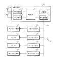
- FIG. 2 is a block diagram illustrating the internal configuration of the in-vehicle control device 10.
- the in-vehicle control device 10 includes an in-vehicle communication unit 110, a body ECU 120, an engine ECU 130, an air conditioner ECU 140, an audio ECU 150, and the like that are connected to each other via a CAN bus 100.
- the in-vehicle communication unit 110 includes a control unit 111, a storage unit 112, an RF reception unit 113, an LF transmission unit 114, an in-vehicle communication unit 115, and the like.
- the control unit 111 includes, for example, a CPU (Central Processing Unit), a ROM (Read Only Memory), a RAM (Random Access Memory), and the like.
- the CPU in the control unit 111 controls the operation of each hardware included in the in-vehicle communication unit 110 by executing a control program stored in the ROM or the storage unit 112.
- the storage unit 112 is configured by a non-volatile memory such as an EEPROM (ElectronicallyrasErasable Programmable Read Only Memory), for example, for executing wireless communication processing with the portable device 20A, CAN communication processing with each of the ECUs 120 to 150, and the like.
- EEPROM ElectricallyrasErasable Programmable Read Only Memory
- the control program is stored.
- the RF reception unit 113 is connected to the RF reception antenna 113a, receives a signal having a frequency in the RF band through the RF reception antenna 113a, and receives a received signal strength (RSSI: Received Signal Strength Strength Indicator).
- RSSI Received Signal Strength Strength Indicator
- a measurement circuit for measuring is provided.
- the RF receiving unit 113 receives a control signal transmitted from the portable device 20A through the RF receiving antenna 113a, and sends the received control signal to the control unit 111.
- the control unit 111 performs an authentication process to determine whether or not the control signal received from the RF receiving unit 113 is a control signal addressed to the own device. ECU 130).
- the LF transmission unit 114 includes a signal generation circuit that generates a signal having a frequency in the LF band (LF: Low Frequency) from a signal output from the control unit 111, an amplification circuit that amplifies the generated signal, and the like. The later signal is transmitted to the outside from the LF transmission antenna 114a. In response to an instruction from the control unit 111, the LF transmission unit 114 transmits a detection signal for detecting the portable device 20A through the LF transmission antenna 114a.
- LF Low Frequency
- the in-vehicle communication unit 115 includes, for example, a CAN communication interface, and is communicably connected to ECUs such as the body ECU 120, the engine ECU 130, the air conditioner ECU 140, and the audio ECU 150 via the CAN bus 100.
- the in-vehicle communication unit 115 transmits / receives signals to / from the body ECU 120, the engine ECU 130, the air conditioner ECU 140, and the audio ECU 150 according to the CAN protocol.
- the body ECU 120 is connected to the door lock mechanism 121. For example, by operating the door lock mechanism 121 based on a control signal transmitted from the in-vehicle communication unit 110, the body ECU 120 locks or unlocks a vehicle door not shown in the figure. Control.
- the engine ECU 130 is connected to the engine 131 of the vehicle C, and performs control for operating the engine 131 based on a control signal transmitted from the in-vehicle communication unit 110, for example.
- the air conditioner ECU 140 is connected to an air conditioner 141 provided in the passenger compartment, and performs control for operating the air conditioner 141 based on a control signal transmitted from the in-vehicle communication unit 110, for example.
- the audio ECU 150 is connected to an audio device 151 provided in the vehicle interior, and performs control for operating the audio device 151 based on a control signal transmitted from the in-vehicle communication unit 110, for example.
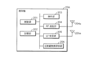
- FIG. 3 is a block diagram illustrating the internal configuration of the portable device 20A.
- the portable device 20A includes a control unit 201, a storage unit 202, an operation unit 203, an RF transmission unit 204, an LF reception unit 205, a short-range wireless communication unit 206, and the like.
- the control unit 201 includes, for example, a CPU and a ROM.
- the CPU in the control unit 201 executes the control program stored in the ROM, thereby controlling the operation of each hardware included in the portable device 20A and causing the entire device to function as the portable device of the in-vehicle control system according to the present application.
- the control unit 201 may include functions such as a timer that measures an elapsed time from when a measurement start instruction is given to when a measurement end instruction is given, and a counter that counts the number.
- the storage unit 202 includes a nonvolatile memory such as an EEPROM, and stores identification information for identifying the portable device 20A.
- the identification information for identifying the portable device 20A is, for example, the ID number of the portable device 20A, the ID number of the vehicle C on which the vehicle-mounted control device 10 serving as a communication partner is mounted, and key information used for encryption processing.
- the operation unit 203 includes an interface for accepting an operation by the user.
- the operation unit 203 includes an operation button for receiving an operation for starting the engine 131 of the vehicle C, for example.
- the control unit 201 of the portable device 20 ⁇ / b> A sends a control signal instructing engine start to the RF transmission unit 204 when an operation by the user is received by the operation unit 203.
- the RF transmission unit 204 includes a signal generation circuit that generates a signal having an RF band frequency from the control signal output from the control unit 201, an amplification circuit that amplifies the generated signal, and the like. It transmits to the outside from the transmitting antenna 204a. In the present embodiment, the RF transmission unit 204 transmits a control signal instructed to start the engine input from the control unit 201 from the RF transmission antenna 204a.
- the LF reception unit 205 is connected to the LF reception antenna 205a, and includes a reception circuit that receives a signal having a frequency in the LF band through the LF reception antenna 205a, a measurement circuit that measures the signal strength of the received signal, and the like.
- LF reception section 205 receives a detection signal transmitted from LF transmission antenna 114 a of vehicle C by LF reception antenna 205 a and sends the received detection signal to control section 201.
- the control unit 201 receives a detection signal from the LF reception unit 205, the control unit 201 performs processing for transmitting a response signal to the detection signal from the RF transmission unit 204.
- the short-range wireless communication unit 206 includes, for example, an NFC chip, an NFC transmission / reception antenna, and an NFC memory, and is configured to operate with power supplied from the NFC reader / writer 31 through short-range wireless communication, for example. That is, the portable device 20A approaches within the communication distance range (for example, 10 cm or less) of the NFC reader / writer, and the radio wave transmitted from the NFC reader / writer 31 is transmitted to the NFC transmission / reception antenna provided in the short-range wireless communication unit 206 on the portable device 20A side. When received, power is induced.
- the NFC chip of the near field communication unit 206 acquires a request command from the NFC reader / writer 31 through near field communication with the NFC reader / writer 31.
- the NFC chip of the near field communication unit 206 reads information stored in the NFC memory, sends a request command to the control unit 201 of the portable device 20A, and the like. Execute.
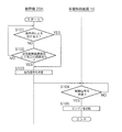
- FIG. 4 is a flowchart for explaining a procedure of processing executed in the in-vehicle control system according to the first embodiment.
- the control unit 201 of the portable device 20A determines whether or not the operation unit 203 has accepted an operation by the user (step S101).
- the control unit 201 executes a process of step S103 described later.
- the control unit 201 determines whether or not the short-range wireless communication unit 206 has performed predetermined communication (step S102). .
- the control unit 201 may determine that predetermined communication has been performed when short-range wireless communication is performed between the short-range wireless communication unit 206 and the NFC reader / writer 31.
- the control unit 201 determines that the short-range wireless communication performed between the short-range wireless communication unit 206 and the NFC reader / writer 31 includes a message indicating that the payment processing is completed, the control unit 201 performs predetermined communication. You may decide that Further, the control unit 201 may determine that the predetermined communication is performed when it is determined that the communication is performed according to the communication protocol defined in the short-range wireless communication.
- control unit 201 If it is determined that the predetermined communication is not performed (S102: NO), the control unit 201 returns the process to step S101.
- step S101 When it is determined in step S101 that an operation by the user has been accepted (S101: YES), or when it is determined that predetermined communication has been performed in step S102 (S102: YES), the control unit 201 starts the engine 131 of the vehicle C.
- the control signal for transmitting is transmitted through the RF transmitter 204 (step S103).
- the control unit 111 of the in-vehicle communication unit 110 periodically determines whether or not the RF reception unit 113 has received a control signal transmitted from the portable device 20A (step S104). If it is determined that it has not been received (S104: NO), the controller 111 waits until a control signal is received from the portable device 20A.
- control unit 111 When it is determined that the control signal from the portable device 20A has been received (S104: YES), the control unit 111 sends the received control signal to the CAN bus 100 and starts the engine 131 through the engine ECU 130 (step S105).
- a control signal is received from the portable device 20A, an authentication process is performed to determine whether the control signal is valid from the portable device, and the control signal is transmitted to the CAN bus only when the authentication is successful. It is good also as a structure sent to 100.
- the operation unit 203 of the portable device 20A when predetermined communication is performed between the portable device 20A and the NFC reader / writer 31 installed as a payment system in the store, the operation unit 203 of the portable device 20A is operated. Even if not, a control signal for starting the engine 131 is transmitted from the portable device 20A to the vehicle C. That is, in the first embodiment, when the payment associated with product purchase at the store is completed and it can be determined that the user is likely to get into the vehicle C, the user operates the operation unit 203 of the portable device 20A. Without stopping, the engine 131 of the vehicle C can be started in advance.
- the control signal is transmitted from the portable device 20A.
- a prohibition button is provided on the portable device 20A, and a predetermined communication is performed between the portable device 20A and the NFC reader / writer 31 while the prohibition button is pressed. Alternatively, transmission of the control signal may be prohibited.
- the engine 131 of the vehicle C is started based on the control signal transmitted from the portable device 20A.
- the electric vehicle is driven by the electric power supplied from the driving battery.
- the driving battery may be operated based on a control signal transmitted from the portable device 20A.
- the portable device 20A includes the operation unit 203 that receives an operation for starting the engine 131.
- the portable device 20A includes an operation unit for operating the door lock mechanism 121.
- a control signal for operating the door lock mechanism 121 may be transmitted from the portable device 20A. .
- the portable device 20A includes an operation unit for operating the air conditioner 141 or the audio device 151.
- the operation unit When the operation unit is operated, or the short-range wireless communication unit 206 of the portable device 20A is connected to the NFC reader / writer 31 in advance.
- a control signal for operating the air conditioner 141 or the audio device 151 may be transmitted from the portable device 20A.
- the air conditioner 141 or the audio device 151 of the vehicle C can be turned on at the same time as the payment of the fee is completed, and the vehicle-mounted control that is more comfortable for the user is possible.
- FIG. 5 is a schematic diagram illustrating a schematic configuration of the in-vehicle control system according to the second embodiment.
- the in-vehicle control system according to the second embodiment is mounted on the vehicle C, and controls the operation of equipment such as the door lock mechanism 121, the engine 131, the air conditioner 141, the audio device 151, and the like.
- a mobile device 20B that is carried by a user and transmits a control signal for operating the equipment of the vehicle C to the in-vehicle control device 10 and a mobile phone 21 that can use the settlement processing system on the store side are provided.
- the portable device 20B includes an operation unit 203 that receives an operation for starting the engine 131 of the vehicle C.
- a control signal for starting the engine 131 is transmitted. It is configured.
- the control signal transmitted from the portable device 20B is a signal having a frequency of 300 to 900 MHz such as an RF band and a specific low power frequency band, and has a communication distance of about several tens of meters to several hundreds of meters.
- the in-vehicle control device 10 is configured to control the start of the engine 131 of the vehicle C when receiving a control signal transmitted from the portable device 20B. Therefore, the user can start the engine 131 from a place away from the vehicle C by operating the operation unit 203 of the portable device 20B.
- the mobile device 20B has a function of communicating with the mobile phone 21 and performs predetermined communication with the mobile phone 21 even when a user operation on the operation unit 203 is not accepted.
- the control signal is transmitted to the in-vehicle control device 10.
- Bluetooth between the mobile phone 21 and the mobile device 20B is performed. (Registered trademark) or wireless communication using a wireless LAN is performed, and a control signal for starting the engine 131 is transmitted from the portable device 20B to the in-vehicle control device 10 with the wireless communication as a trigger.
- FIG. 6 is a block diagram illustrating the internal configuration of the portable device 20B.
- the portable device 20B includes a wireless communication unit 207 in addition to the control unit 201, the storage unit 202, the operation unit 203, the RF transmission unit 204, and the LF reception unit 205 described above.
- the wireless communication unit 207 has a function of performing wireless communication by Bluetooth (registered trademark) with another paired communication device (the mobile phone 21 in the second embodiment), or connected to the wireless LAN, and others via the wireless LAN. Wireless communication with the other communication device (cell phone 21).
- Bluetooth registered trademark
- the wireless communication unit 207 has a function of performing wireless communication by Bluetooth (registered trademark) with another paired communication device (the mobile phone 21 in the second embodiment), or connected to the wireless LAN, and others via the wireless LAN. Wireless communication with the other communication device (cell phone 21).
- FIG. 7 is a flowchart for explaining a procedure of processes executed in the in-vehicle control system according to the second embodiment.
- the control unit 201 of the portable device 20B determines whether or not an operation by the user is accepted by the operation unit 203 (step S201).
- the control unit 201 executes a process of step S203 described later.
- the control unit 201 determines whether or not the wireless communication unit 207 has performed predetermined communication (step S202).
- the control unit 201 may determine that predetermined communication has been performed when wireless communication using Bluetooth (registered trademark) or a wireless LAN is performed between the wireless communication unit 207 and the mobile phone 21.
- the control unit 201 may determine that a predetermined communication has been performed.
- the control unit 201 may determine that predetermined communication has been performed when it is determined that communication has been performed in accordance with a communication protocol defined by Bluetooth (registered trademark) or wireless LAN.
- control unit 201 If it is determined that the predetermined communication is not performed (S202: NO), the control unit 201 returns the process to step S201.
- step S201 When it is determined in step S201 that an operation by the user has been accepted (S201: YES), or when it is determined that predetermined communication has been performed in step S202 (S202: YES), the control unit 201 starts the engine 131 of the vehicle C.
- the control signal for transmitting is transmitted through the RF transmission unit 204 (step S203).
- the control unit 111 of the in-vehicle communication unit 110 periodically determines whether or not the RF reception unit 113 has received a control signal transmitted from the portable device 20B (step S204). If it is determined that it has not been received (S204: NO), the control unit 111 waits until a control signal is received from the portable device 20B.
- control unit 111 sends the received control signal to the CAN bus 100 and starts the engine 131 through the engine ECU 130 (step S205).
- a control signal is received from the portable device 20B, an authentication process is performed to determine whether the control signal is valid from the portable device, and the control signal is transmitted to the CAN bus only when the authentication is successful. It is good also as a structure sent to 100.
- the operation unit 203 of the mobile device 20B is not operated.
- a control signal for starting the engine 131 is transmitted from the portable device 20B to the vehicle C. That is, in the second embodiment, when the payment associated with product purchase at the store is completed and it can be determined that the user is likely to get into the vehicle C, the user operates the operation unit 203 of the portable device 20B. Without stopping, the engine 131 of the vehicle C can be started in advance.
- the control signal is transmitted from the portable device 20B. Since C is not necessarily driven, a prohibition button is provided on the portable device 20B. While the prohibition button is pressed, even if communication is performed between the portable device 20B and the cellular phone 21, the control signal May be prohibited.
- the engine 131 of the vehicle C is started based on the control signal transmitted from the portable device 20B.
- the electric vehicle in which the vehicle C is driven by the electric power supplied from the driving battery may be operated based on a control signal transmitted from the portable device 20B.
- the portable device 20B includes the operation unit 203 that receives an operation for starting the engine 131.
- the portable device 20B includes an operation unit for operating the door lock mechanism 121.
- a control signal for operating the door lock mechanism 121 may be transmitted from the mobile device 20B.
- the portable device 20B includes an operation unit for operating the air conditioner 141 or the audio device 151, and when the operation unit is operated or when the predetermined communication is performed between the portable device 20B and the mobile phone 21.
- a configuration may be adopted in which a control signal for operating the air conditioner 141 or the audio device 151 is transmitted from the portable device 20B.
- Embodiment 3 when wireless communication is performed between the detection system and a portable device using a detection system for detecting the presence or absence of a user who passes through a designated area, the vehicle-mounted control is performed from the portable device. A configuration for transmitting a control signal for starting the engine to the apparatus 10 will be described. In addition, since the structure of the vehicle-mounted control apparatus 10 is the same as that of Embodiment 1, it abbreviate
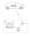
- FIG. 8 is a schematic diagram illustrating a schematic configuration of the in-vehicle control system according to the third embodiment.
- the in-vehicle control system according to the third embodiment is mounted on a vehicle C, and controls the operation of equipment such as the door lock mechanism 121, the engine 131, the air conditioner 141, the audio device 151, and the in-vehicle control device.
- 10 includes a portable device 20 ⁇ / b> C that transmits a control signal for operating the equipment of the vehicle C to 10.
- the portable device 20C includes, for example, an operation unit 203 that receives an operation for starting the engine 131 of the vehicle C. When the operation unit 203 is operated by a user, a control signal for starting the engine 131 is transmitted. It is configured.
- the control signal transmitted from the portable device 20C is a signal having a frequency of 300 to 900 MHz such as an RF band and a specific low power frequency band, and has a communication distance of about several tens of meters to several hundreds of meters.
- the in-vehicle control device 10 is configured to control the start of the engine 131 of the vehicle C when receiving a control signal transmitted from the portable device 20C. Therefore, the user can start the engine 131 from a place away from the vehicle C by operating the operation unit 203 of the portable device 20C.
- the portable device 20C is configured to perform wireless communication with the exit management device 40 that manages the exit of the user from a predetermined area (management area). Even when the user's operation is not accepted, the control signal is transmitted to the in-vehicle control device 10 when predetermined communication is performed with the exit management device 40.
- the exit management device 40 is provided at an entrance of a building or a ticket gate of a station, and transmits an LF band signal at a predetermined time interval in order to detect a user carrying the portable device 20C. 41 and an RF receiving antenna 42 that receives an RF band response signal transmitted from the portable device 20C that has received the signal transmitted from the LF transmitting antenna 41.
- the portable device 20C receives a signal transmitted from the LF transmission antenna 41 of the exit management device 40, it is determined that predetermined communication has been performed, and the engine 131 is transmitted from the portable device 20C to the in-vehicle control device 10. The control signal for starting is transmitted.
- FIG. 9 is a block diagram illustrating the internal configuration of the portable device 20C.
- the portable device 20C includes the control unit 201, the storage unit 202, the operation unit 203, the RF transmission unit 204, and the LF reception unit 205 described above.
- the LF reception unit 205 is configured to receive not only a signal from the LF transmission unit 114 included in the in-vehicle communication unit 110 of the in-vehicle control device 10 but also an LF band signal transmitted from the exit management device 40.
- the RF transmission unit 204 receives an LF band signal transmitted from the LF transmission unit 114 of the in-vehicle communication unit 110 or an LF band signal transmitted from the exit management device 40, the LF reception unit 205, A response signal for the signal is transmitted.
- FIG. 10 is a flowchart for explaining a procedure of processes executed in the in-vehicle control system according to the third embodiment.
- the control unit 201 of the portable device 20C determines whether or not the operation unit 203 has accepted an operation by the user (step S301).
- the control unit 201 executes a process of step S303 described later.
- the control unit 201 determines whether or not predetermined communication is performed by the LF reception unit 205 (step S302).
- the control unit 201 may determine that predetermined communication has been performed when the LF reception unit 205 receives an LF band signal from the exit management device 40. Further, when the control unit 201 determines that the LF reception unit 205 has received a message including information for identifying the exit management device 40 as transmission source identification information, the control unit 201 may determine that predetermined communication has been performed. . Further, when the control unit 201 determines that communication is performed according to a communication protocol that defines a procedure for transmitting and receiving LF band signals, the control unit 201 may determine that predetermined communication has been performed.
- control unit 201 If it is determined that the predetermined communication is not performed (S302: NO), the control unit 201 returns the process to step S301.
- step S301 When it is determined in step S301 that an operation by the user has been accepted (S301: YES), or when it is determined that predetermined communication has been performed in step S302 (S302: YES), the control unit 201 starts the engine 131 of the vehicle C.
- the control signal for transmitting is transmitted through the RF transmission unit 204 (step S303).
- the control unit 111 of the in-vehicle communication unit 110 periodically determines whether or not the RF reception unit 113 has received a control signal transmitted from the portable device 20C (step S304). If it is determined that it has not been received (S304: NO), the controller 111 waits until a control signal is received from the portable device 20C.
- control unit 111 sends the received control signal to the CAN bus 100 and starts the engine 131 through the engine ECU 130 (step S305).
- a control signal is received from the portable device 20C, an authentication process is performed to determine whether the control signal is valid from the portable device, and the control signal is transmitted to the CAN bus only when the authentication is successful. It is good also as a structure sent to 100.
- the portable device 20C when communication with the exit management device 40 is performed, even if the operation unit 203 of the portable device 20C is not operated, the portable device 20C is connected to the vehicle C. Then, a control signal for starting the engine 131 is transmitted. That is, in the third embodiment, when it is determined that there is a high possibility that the user leaves the management area and gets into the vehicle C, the user does not operate the operation unit 203 of the portable device 20C in advance. The engine 131 can be started.
- the control signal when communication is performed between the portable device 20C and the exit management device 40, the control signal is transmitted from the portable device 20C.
- the vehicle C Since it does not necessarily drive, a prohibit button is provided on the portable device 20C, and when the prohibit button is pressed, transmission of a control signal is prohibited even if communication is performed between the portable device 20C and the exit management device 40. You may be able to do it.
- the engine 131 of the vehicle C is started based on the control signal transmitted from the portable device 20C.
- the electric vehicle is driven by the electric power supplied from the driving battery.
- the driving battery may be operated based on a control signal transmitted from the portable device 20C.
- the portable device 20C includes the operation unit 203 that receives an operation for starting the engine 131.
- the portable device 20C includes an operation unit for operating the door lock mechanism 121.
- a configuration may be adopted in which a control signal for operating the door lock mechanism 121 is transmitted from the portable device 20C.
- the portable device 20C includes an operation unit for operating the air conditioner 141 or the audio device 151, and when the operation unit is operated, or when the predetermined communication is performed between the portable device 20C and the exit management device 40. In such a case, a control signal for operating the air conditioner 141 or the audio device 151 may be transmitted from the portable device 20C.
Landscapes
- Engineering & Computer Science (AREA)
- Business, Economics & Management (AREA)
- Physics & Mathematics (AREA)
- General Physics & Mathematics (AREA)
- Accounting & Taxation (AREA)
- Computer Networks & Wireless Communication (AREA)
- Strategic Management (AREA)
- Theoretical Computer Science (AREA)
- General Business, Economics & Management (AREA)
- Mechanical Engineering (AREA)
- Finance (AREA)
- Signal Processing (AREA)
- General Engineering & Computer Science (AREA)
- Chemical & Material Sciences (AREA)
- Combustion & Propulsion (AREA)
- Thermal Sciences (AREA)
- Marketing (AREA)
- Economics (AREA)
- Development Economics (AREA)
- Selective Calling Equipment (AREA)
- Lock And Its Accessories (AREA)
- Air-Conditioning For Vehicles (AREA)
- Cash Registers Or Receiving Machines (AREA)
- Control Of Vehicle Engines Or Engines For Specific Uses (AREA)
Priority Applications (1)
| Application Number | Priority Date | Filing Date | Title |
|---|---|---|---|
| US16/082,757 US20190085810A1 (en) | 2016-03-25 | 2017-03-13 | On-board control system and portable device |
Applications Claiming Priority (2)
| Application Number | Priority Date | Filing Date | Title |
|---|---|---|---|
| JP2016-062336 | 2016-03-25 | ||
| JP2016062336A JP2017172563A (ja) | 2016-03-25 | 2016-03-25 | 車載制御システム及び携帯機 |
Publications (1)
| Publication Number | Publication Date |
|---|---|
| WO2017163951A1 true WO2017163951A1 (ja) | 2017-09-28 |
Family
ID=59900204
Family Applications (1)
| Application Number | Title | Priority Date | Filing Date |
|---|---|---|---|
| PCT/JP2017/009867 Ceased WO2017163951A1 (ja) | 2016-03-25 | 2017-03-13 | 車載制御システム及び携帯機 |
Country Status (3)
| Country | Link |
|---|---|
| US (1) | US20190085810A1 (enExample) |
| JP (1) | JP2017172563A (enExample) |
| WO (1) | WO2017163951A1 (enExample) |
Families Citing this family (4)
| Publication number | Priority date | Publication date | Assignee | Title |
|---|---|---|---|---|
| US11047355B2 (en) * | 2017-10-02 | 2021-06-29 | Walbro Llc | Multi-function engine control and input system |
| CN107993120B (zh) * | 2017-11-27 | 2022-05-24 | 北京新能源汽车股份有限公司 | 租赁信息配置方法、装置、租赁车机、控制器及租赁平台 |
| US11014428B2 (en) * | 2018-08-22 | 2021-05-25 | Ford Global Technologies, Llc | Controlling climate in vehicle cabins |
| JP7445412B2 (ja) * | 2019-11-15 | 2024-03-07 | 株式会社Subaru | 制御装置および制御システム |
Citations (3)
| Publication number | Priority date | Publication date | Assignee | Title |
|---|---|---|---|---|
| JPH06257542A (ja) * | 1993-03-09 | 1994-09-13 | Calsonic Corp | 自動車エンジンの自動始動装置 |
| JP2008190457A (ja) * | 2007-02-06 | 2008-08-21 | Auto Network Gijutsu Kenkyusho:Kk | 車両用遠隔始動装置 |
| JP2009101927A (ja) * | 2007-10-24 | 2009-05-14 | Toyota Motor Corp | 車両制御装置 |
Family Cites Families (17)
| Publication number | Priority date | Publication date | Assignee | Title |
|---|---|---|---|---|
| JPH09142255A (ja) * | 1995-11-17 | 1997-06-03 | Yazaki Corp | キーレスエントリーシステム用キー装置、キーレスエントリーシステム用車載装置、及び、キーレスエントリーシステム |
| JP2003078593A (ja) * | 2001-08-30 | 2003-03-14 | Auto Network Gijutsu Kenkyusho:Kk | 車載電子制御システム |
| US8907770B2 (en) * | 2008-02-05 | 2014-12-09 | At&T Intellectual Property I, L.P. | System and method of controlling vehicle functions |
| JP5254905B2 (ja) * | 2009-08-24 | 2013-08-07 | 株式会社東海理化電機製作所 | カーシェアリングシステム |
| JP2012041713A (ja) * | 2010-08-18 | 2012-03-01 | Toyota Infotechnology Center Co Ltd | 車両の遠隔制御システム及び遠隔制御方法 |
| DE102010061351A1 (de) * | 2010-12-20 | 2012-06-21 | Huf Hülsbeck & Fürst Gmbh & Co. Kg | Kompakter, eine NFC-Kommunikationsmöglichkeit aufweisender ID-Geber eines Kraftfahrzeug-Zugangssystems |
| US9365188B1 (en) * | 2011-04-22 | 2016-06-14 | Angel A. Penilla | Methods and systems for using cloud services to assign e-keys to access vehicles |
| KR101881167B1 (ko) * | 2011-06-13 | 2018-07-23 | 주식회사 케이티 | 차량 제어 시스템 |
| US8768565B2 (en) * | 2012-05-23 | 2014-07-01 | Enterprise Holdings, Inc. | Rental/car-share vehicle access and management system and method |
| US9454786B1 (en) * | 2013-03-08 | 2016-09-27 | Allstate Insurance Company | Encouraging safe driving using a remote vehicle starter and personalized insurance rates |
| FR3003216B1 (fr) * | 2013-03-13 | 2016-07-01 | Renault Sa | Procede de mise a disposition d'un vehicule et systeme de mise a disposition correspondant |
| DE102014008478B3 (de) * | 2014-06-07 | 2015-08-06 | Audi Ag | Fernsteuern eines Kraftfahrzeugs während einer Parkphase |
| US9483886B2 (en) * | 2014-10-01 | 2016-11-01 | Continental Intelligent Transportation Systems, LLC | Method and system for remote access control |
| DE102014224481B4 (de) * | 2014-12-01 | 2023-08-24 | Bayerische Motoren Werke Aktiengesellschaft | Fernsteuerung von Fahrzeugfunktionalitäten mittels eines mobilen Endgeräts |
| DE102016223862A1 (de) * | 2016-11-30 | 2018-05-30 | Audi Ag | Verfahren zum Betreiben einer Kommunikationseinrichtung eines Kraftfahrzeugs |
| KR20180098017A (ko) * | 2017-02-24 | 2018-09-03 | 엘지전자 주식회사 | 이동 단말기 및 그 제어방법 |
| JP7221589B2 (ja) * | 2017-10-24 | 2023-02-14 | トヨタ自動車株式会社 | 鍵情報管理装置、鍵情報管理方法、鍵情報管理プログラム |
-
2016
- 2016-03-25 JP JP2016062336A patent/JP2017172563A/ja active Pending
-
2017
- 2017-03-13 WO PCT/JP2017/009867 patent/WO2017163951A1/ja not_active Ceased
- 2017-03-13 US US16/082,757 patent/US20190085810A1/en not_active Abandoned
Patent Citations (3)
| Publication number | Priority date | Publication date | Assignee | Title |
|---|---|---|---|---|
| JPH06257542A (ja) * | 1993-03-09 | 1994-09-13 | Calsonic Corp | 自動車エンジンの自動始動装置 |
| JP2008190457A (ja) * | 2007-02-06 | 2008-08-21 | Auto Network Gijutsu Kenkyusho:Kk | 車両用遠隔始動装置 |
| JP2009101927A (ja) * | 2007-10-24 | 2009-05-14 | Toyota Motor Corp | 車両制御装置 |
Also Published As
| Publication number | Publication date |
|---|---|
| JP2017172563A (ja) | 2017-09-28 |
| US20190085810A1 (en) | 2019-03-21 |
Similar Documents
| Publication | Publication Date | Title |
|---|---|---|
| JP6127864B2 (ja) | 車両制御装置及び携帯通信端末 | |
| US10196038B2 (en) | Vehicular communication control system | |
| US10322694B2 (en) | Bluetooth verification for vehicle access systems | |
| JP6294109B2 (ja) | スマートシステム | |
| EP2719584B1 (en) | Electronic key registration system | |
| JP2017538875A (ja) | 乗り物のロック/アンロック及び/又は始動を制御する装置 | |
| CN103312502A (zh) | 通信系统、通信方法以及便携机 | |
| JP2010215001A (ja) | 通信装置および通信方法 | |
| JP6441691B2 (ja) | キー機能管理システム | |
| JP2010028550A (ja) | 通信システム | |
| CN108699860A (zh) | 车门解锁系统以及车载控制装置 | |
| WO2017163951A1 (ja) | 車載制御システム及び携帯機 | |
| JP5391029B2 (ja) | 車両制御システム | |
| JP6414696B2 (ja) | キー閉じ込み防止装置 | |
| JP2012041713A (ja) | 車両の遠隔制御システム及び遠隔制御方法 | |
| CN109697838A (zh) | 钥匙单元、锁定/解锁系统以及存储有程序的计算机可读存储介质 | |
| JP5878355B2 (ja) | 携帯機 | |
| JP2012149472A (ja) | 電子キー登録システム | |
| JP2013219678A (ja) | カーナビゲーションシステムの操作制御装置 | |
| JP2015151039A (ja) | キー情報登録システム | |
| JP5144465B2 (ja) | ネットワーク接続システム | |
| JP6253003B1 (ja) | 電子キーシステム及び該システムに用いられるセキュリティユニット並びに電子キー | |
| KR20210050109A (ko) | 도어 잠금 장치 제어를 위한 모바일 디바이스 및 이를 이용한 도어 잠금 장치 제어 방법, 이를 이용한 출입 제어 시스템 | |
| JP6227054B1 (ja) | 携帯機登録システム | |
| WO2018047748A1 (ja) | 車載通信システム、車載装置及び携帯機 |
Legal Events
| Date | Code | Title | Description |
|---|---|---|---|
| 121 | Ep: the epo has been informed by wipo that ep was designated in this application |
Ref document number: 17769995 Country of ref document: EP Kind code of ref document: A1 |
|
| 122 | Ep: pct application non-entry in european phase |
Ref document number: 17769995 Country of ref document: EP Kind code of ref document: A1 |