WO2017163893A1 - 車両用計器 - Google Patents
車両用計器 Download PDFInfo
- Publication number
- WO2017163893A1 WO2017163893A1 PCT/JP2017/009387 JP2017009387W WO2017163893A1 WO 2017163893 A1 WO2017163893 A1 WO 2017163893A1 JP 2017009387 W JP2017009387 W JP 2017009387W WO 2017163893 A1 WO2017163893 A1 WO 2017163893A1
- Authority
- WO
- WIPO (PCT)
- Prior art keywords
- accumulator
- shaft member
- holder
- pinion
- wall portion
- Prior art date
- Legal status (The legal status is an assumption and is not a legal conclusion. Google has not performed a legal analysis and makes no representation as to the accuracy of the status listed.)
- Ceased
Links
Images





Classifications
-
- G—PHYSICS
- G01—MEASURING; TESTING
- G01D—MEASURING NOT SPECIALLY ADAPTED FOR A SPECIFIC VARIABLE; ARRANGEMENTS FOR MEASURING TWO OR MORE VARIABLES NOT COVERED IN A SINGLE OTHER SUBCLASS; TARIFF METERING APPARATUS; MEASURING OR TESTING NOT OTHERWISE PROVIDED FOR
- G01D7/00—Indicating measured values
-
- G—PHYSICS
- G06—COMPUTING OR CALCULATING; COUNTING
- G06M—COUNTING MECHANISMS; COUNTING OF OBJECTS NOT OTHERWISE PROVIDED FOR
- G06M1/00—Design features of general application
Definitions
- the present invention relates to a vehicle instrument equipped with an accumulator that displays a travel distance.
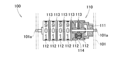
- FIG. 9 is a reproduction of FIG. 1 of Patent Document 1.
- FIG. 10 is a reproduction of FIG. 2 of Patent Document 1.
- the reference numerals were reassigned as appropriate.
- the vehicle meter 100 includes a metal casing 101 and an accumulator 110 that is supported by the casing 101 and displays a travel distance.
- the accumulator 110 includes an accumulator shaft member 111 fixed to the housing 101, a plurality of character wheels 112 rotatably provided on the accumulator shaft member 111, and numerical values on the surface thereof, and these character wheels 112. And a pinion holder 113 that is rotatably disposed on the integrating shaft member 111.
- the pinion holder 113 rotatably supports a pinion gear 114 disposed between character wheels 112 disposed on the left and right.
- the character wheel 112 arranged on the left is sent one numerical value by the pinion gear 114 when the character wheel 112 arranged on the right makes one round.
- Assembling work of the vehicular instrument 100 to the housing 101 is carried out by placing the claw portion 113a formed on the pinion holder 113 on the upper surface of the housing 101 and aligning the pinion holder 113 with an accurate position, This is performed by assembling to the shaft member support portion 101a formed in the housing 101.
- the pinion holder 113 is rotatably attached to the accumulator shaft member 111. For this reason, if the accumulator shaft member 111 is assembled to the housing 101 without pressing the pinion holder 113, the accumulator 110 may be assembled to the housing 101 with the pinion holder 113 being displaced. According to the vehicle instrument 100, two operations must be performed at the same time in order to assemble the integrating shaft member 111 while adjusting the pinion holder 113 to an accurate position.
- An object of the present invention is to provide an instrument for a vehicle in which an integrating meter can be easily assembled to a housing.
- the rotating body that rotates in conjunction with the rotation of the wheel, the accumulator that displays the travel distance by rotating the character wheel on which the numerical value is described based on the rotation of the rotating body, and these A rotating body and a housing that rotatably supports the integrator
- the accumulator is arranged between an accumulator shaft member fixed to the casing, a plurality of the character wheels rotatably provided on the accumulator shaft member, and the accumulator
- a pinion holder that is rotatably provided on the meter shaft member, and a pinion gear that is rotatably supported by the pinion holder and disposed between the character wheels disposed on the left and right
- the character wheel arranged on the left is a vehicle meter in which the numerical value is sent by the pinion gear by one turn of the character wheel arranged on the right
- the housing includes a storage unit that stores at least the lower half of the integrator,
- the storage portion includes a shaft member support portion on which the accumulator shaft member is supported, a
- the front lower end portion of the front protrusion is formed to have a downward slope toward the rear, and the rear lower end portion of the rear protrusion has a downward slope to the front. Is formed.
- the pinion holder has a front protrusion protruding from the holder main body part to the vicinity of the front wall part, and a rear protrusion part protruding to the vicinity of the rear wall part.
- the front protrusion is in contact with the front wall, or the rear protrusion is in contact with the rear wall. Since the pinion holder is rotatably provided on the accumulator shaft member, the pinion holder is rotated when the protruding portion formed on the holder contacts the wall portion formed on the storage portion. Further, by pushing the accumulator, the pinion holder is guided to an accurate position by the wall portion formed in the storage portion.
- the front lower end part of the front part protrusion part is formed in the downward slope toward back, and the rear lower end part of the rear part protrusion part is formed in the downward slope toward the front. . If the pinion holder is displaced in the rotation direction when the accumulator is assembled to the housing, the front lower end or the rear lower end contacts the housing. Since these portions are formed in a tapered shape, the pinion holder can be easily rotated. Assembly workability can be improved.
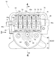
- FIG. 2 is a plan view of the vehicle instrument shown in FIG. 1.
- FIG. 3 is a view taken in the direction of arrow 3 in FIG. 2.
- FIG. 4 is a sectional view taken along line 4-4 of FIG.
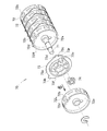
- FIG. 3 is an exploded perspective view of the integrator shown in FIG. 2.
- FIG. 6 is a view taken along arrow 6 in FIG. 5. It is a figure explaining the assembly
- left and right refer to the left and right based on the vehicle occupant
- front and rear refer to the front and rear based on the traveling direction of the vehicle.
- the vehicle instrument 10 is used, for example, in a two-wheeled vehicle, and a vehicle speed meter 50 and an accumulator 70 are assembled to a housing 20.
- the vehicle speedometer 50 is an eddy current type instrument that displays the traveling speed of the vehicle.
- the accumulator 70 displays the travel distance of the vehicle.
- the housing 20 includes a plate-like base portion 21 and a resin lid body 30 that covers the base portion 21.
- the vehicle speedometer 50 is supported by a metal cylindrical member 51 fixed to the base 21, a metal sliding bearing 52 provided on the inner periphery of the cylindrical member 51, and the sliding bearing 52 so as to be rotatable.
- the first rotating shaft 53 (rotating body 53), a cup-shaped magnetic body 54 fixed to the upper portion of the first rotating shaft 53, and the first rotating shaft 53 accommodated in the magnetic body 54.
- a magnet 55 fixed to the upper portion of the first rotating shaft 53, a sliding bearing 56 housed in a hole formed at the upper end of the first rotating shaft 53, and a second rotating shaft whose lower end is rotatably supported by the sliding bearing 56.
- the accumulator 70 includes an accumulator shaft member 71 fixed to the lid body 30 (see FIG. 2), six character wheels 72 rotatably provided on the accumulator shaft member 71, and the character wheels 72.
- the pinion holder 73 is disposed between the pinion holders 73 and is rotatably supported by the pinion holder 73, and the character wheel 72 is rotatably supported by the pinion holders 73 and disposed on the left and right.
- the pinion gear 74 is provided.
- the base 21 is configured by, for example, press forming a cold rolled steel plate.
- the base 21 has an insertion hole 21a into which the tubular member 51 is inserted substantially at the center.
- the lid body 30 is, for example, an injection-molded product molded by injection molding, and a lid body wall portion 31 raised from the base portion 21 and a ceiling portion extending in parallel to the base portion 21 from the upper end of the lid body wall portion 31. 32 and a box-shaped storage unit 40 that stores the accumulator 70 adjacent to the ceiling unit 32.
- Polybutylene terephthalate can be used for the resin of the lid 30.
- a circular insertion hole 32a is formed on the axis CL of the first rotation shaft 53.
- a metal second rotating shaft 57 is inserted into the insertion hole 32a. That is, the second rotation shaft 57 is disposed on the same axis line CL as the first rotation shaft 53.
- the ceiling portion 32 includes a cylindrical resistance portion 32b extending downward.
- the resistance portion 32 b has a tip immersed in the damper oil 61 and suppresses the rotation of the rotor 63.
- the resistance portion 32 b regulates the thrust direction of the rotor 63 by abutting against the bottom surface of the oil cup 62.
- the storage unit 40 is formed in a box shape in which the lower half of the integrator 70 can be stored and the upper part is opened.
- the storage portion 40 includes a bottom portion 41, a front wall portion 42 that is raised substantially vertically from the front end portion of the bottom portion 41, and a rear wall portion 43 that is raised from the rear end of the bottom portion 41. .
- the bottom portion 41 has a front portion formed in a flat shape and a rear portion formed in a 90 ° circular arc shape along the character wheel 72.
- the upper end of the front wall portion 42 includes a front guide portion 42a formed with a downward slope toward the rear so that the accumulator 70 can be easily stored in the storage portion 40.
- the upper end of the rear wall portion 43 has a rear guide portion 43a (with a downward slope toward the front so that the accumulator 70 can be easily stored in the storage portion 40. (See FIG. 8).
- the left and right end portions of the storage portion 40 are closed by the left wall portion 44 and the right wall portion 45, respectively.
- the left wall 44 is formed with a substantially U-shaped shaft member support 44 a that opens upward to support the accumulator shaft member 71.
- the shaft member support portion 44a is a part where the accumulator shaft member 71 can be assembled from above.
- the left wall portion 44 is integrally formed with a bent portion 44b that is bent in the front-rear direction and a stopper 44c that is positioned at the upper end of the bent portion 44b and prevents the integrating meter shaft member 71 from coming off.
- the stopper 44c is formed with a tapered surface portion 44d inclined from the extending direction of the shaft member support portion 44a from the upper end.
- the right wall portion 45 is formed with a shaft member insertion hole 45a into which the right end portion of the accumulator shaft member 71 is inserted.
- the shaft member support portion 44 a may be formed in the right wall portion 45, and the shaft member insertion hole 45 a may be formed in the left wall portion 44.
- the bent portion 44b, the stopper 44c, and the tapered surface portion 44d are formed integrally with the right wall portion 45.
- the magnet 55 is a radially magnetized sintered magnet made of, for example, AlNiCo, and rotates at a rotational speed proportional to the traveling speed of the vehicle by inserting a cable from the vehicle into the first rotating shaft 53. To do.
- the second rotating shaft 57, the oil cup 62, and the rotor 63 are integrally coupled by insert molding.
- the rotor 63 is made of a nonmagnetic metal such as aluminum, and is formed in a cup shape by press molding. The rotor 63 is disposed so as not to contact the magnet 55 so as to cover the magnet 55.
- the end of the beard spring 64 is fixed to the lid body 30 by heat caulking or the like.
- the worm 65 is rotated by the rotation of the wheel portion 53a.
- the rotational force of the worm 65 is transmitted to the accumulator 70. That is, the numerical value displayed by the accumulator 70 is proportional to the rotation amount of the worm 65.
- a known mechanism can be adopted as a mechanism for transmitting the rotational force of the first rotating shaft 53 to the accumulator 70.
- a flexible cable can be connected to the lower end of the first rotating shaft 53.
- the flexible cable transmits the rotation of the wheel to the first rotation shaft 53. That is, the first rotating shaft 53 rotates in conjunction with the rotation of the wheel.
- the first rotating shaft 53 rotates, and the magnetic conductor 54 and the magnet 55 fixed to the first rotating shaft 53 rotate integrally.
- the base 21, the cylindrical member 51, and the sliding bearing 52 do not rotate.
- Rotating the first rotating shaft 53, the magnet 55, and the magnetic conductor 54 generates an eddy current. Due to this eddy current, a force is applied to the rotor 63 in the rotational direction. As the speed at which the magnet 55 rotates increases, the eddy current increases. When the eddy current increases, the rotor 63 rotates against the biasing force of the whisker spring 64. When the rotor 63 rotates, the second rotating shaft 57 and the oil cup 62 rotate. As the second rotating shaft 57 rotates, the pointer 67 (see FIG. 1) fixed to the tip of the second rotating shaft 57 also rotates. On the other hand, the lid body 30, the resistance portion 32b, and the whisker spring 64 do not rotate.
- the rotation speed of the first rotating shaft 53 also decreases. Thereby, an eddy current becomes small. Due to the urging force of the whisker spring 64, the second rotary shaft 57 is rotated in the direction opposite to that during acceleration. When the two-wheeled vehicle is stopped, the second rotating shaft 57 and the pointer 67 are returned to the positions before the two-wheeled vehicle travels.
- the oil cup 62 can rotate, and the resistance portion 32b cannot rotate.
- a damper oil 61 is filled in the oil cup 62.
- a force is also applied to the oil cup 62 in the direction of suppressing rotation.
- the force for suppressing this rotation is applied to the oil cup 62 during acceleration and deceleration. Thereby, rapid rotation of the second rotating shaft 57 and the rotor 63 is suppressed. By suppressing rapid rotation, the movement of the pointer 67 is suppressed.
- the character wheel 72 has a cylindrical shape having left and right partition walls 72a in the center. On the circumferential surface of the character wheel 72, a numerical value 72b for indicating a travel distance is displayed.
- the right side surface portion of the letter wheel 72 is formed in an internal gear shape.
- the left side surface portion of the dial wheel 72 is formed in an internal gear shape in which the number of teeth 72d that is 1/10 of the number of teeth 72c formed on the right side surface portion (two) is formed. All character wheels 72 have the same configuration.
- Character wheels 72R and 72L (in this paragraph, R is a subscript indicating the right and L is a subscript indicating the left) are arranged on the left and right of the pinion holder 73, respectively.
- R is a subscript indicating the right and L is a subscript indicating the left
- the pinion gear 74 is rotated by further rotating the right character wheel 72R.
- the pinion gear 74 is provided between the left and right character wheels 72R and 72L.
- teeth 72c are formed entirely on the right side surface of the right character wheel 72R. For this reason, the right letter wheel 72 ⁇ / b> R is rotated by the pinion gear 74.
- one numerical value 72b described on the surface of the right character wheel 72R is sent. That is, the character wheel 72L arranged on the left is sent one numerical value 72b by the pinion gear 74 when the character wheel 72R arranged on the right makes one round.
- the pinion holder 73 includes a holder main body 73a having a circular shape centering on the accumulator shaft member 71, a front protrusion 73b protruding from the holder main body 73a to the vicinity of the front wall 42, and a holder main body 73a.
- a rear projecting portion 73c projecting to the vicinity of the rear wall portion 43, a contact preventing portion 73d formed continuously from the upper portion of the rear projecting portion 73c to prevent the character wheel 72 from contacting the whisker spring 64, and a pinion gear And a pinion gear support portion 73e for supporting 74.
- the front lower end 73f of the front protrusion 73b is formed to have a downward slope toward the rear.
- the rear lower end 73r of the rear protrusion 73c is formed to have a downward slope toward the front.
- FIG. 7A a method of assembling the accumulator 70 to the storage unit 40 will be described. As shown in FIG. 7A, first, one end (right end) of the accumulator shaft member 71 is inserted into the shaft member insertion hole 45a. Next, the other end portion (left end portion) of the integrating meter shaft member 71 is assembled to the shaft member support portion 44a. Since the shaft member support portion 44a is open upward, the accumulator shaft member 71 is assembled from above.
- the bending portion 44b is bent by pushing the integrating shaft member 71.
- the accumulator shaft member 71 is assembled to the shaft member support portion 44a.
- the bending portion 44b is not bent.
- the stopper 44c is positioned above the accumulator shaft member 71 and prevents the accumulator shaft member 71 from coming off.
- the pinion holder 73 is provided so as to be rotatable with respect to the accumulator shaft member 71. For this reason, when the pinion holder 73 is stored in the storage unit 40, the pinion holder 73 can rotate.
- the shaft member support portion 44a is a part to which the accumulator shaft member 71 can be attached from above.
- the pinion holder 73 has a front protrusion 73 b that protrudes from the holder main body 73 a to the vicinity of the front wall 42, and a rear protrusion 73 c that protrudes to the vicinity of the rear wall 43.
- the accumulator 70 is assembled to the housing 20 from above the storage unit 40. At this time, when the pinion holder 73 is displaced in the rotation direction, the front protrusion 73 b comes into contact with the front wall 42, or the rear protrusion 73 c comes into contact with the rear wall 43.
- the pinion holder 73 Since the pinion holder 73 is rotatably provided on the accumulator shaft member 71, the projections 73 b and 73 c formed on the pinion holder 73 come into contact with the wall portions 42 and 43 formed on the storage unit 40. It is rotated. Further, by pushing down the accumulator 70, the pinion holder 73 is guided to an accurate position by the wall portions 42 and 43 formed in the storage portion 40. For this reason, there is no need to assemble the housing 20 while holding the pinion holder 73 during the work of attaching the accumulator 70. It is possible to provide the vehicle instrument 10 in which the accumulator 70 can be easily assembled to the housing 20.
- the front lower end 73f of the front protrusion 73b is formed with a downward slope toward the rear
- the rear lower end 73r of the rear protrusion 73c is formed with a downward slope toward the front. If the pinion holder 73 is displaced in the rotation direction when the accumulator 70 is assembled to the housing 20, the front lower end 73 f or the rear lower end 73 r contacts the housing 20. Since these portions are formed in a tapered shape, the pinion holder 73 can be easily rotated. Assembly workability can be improved.
- the upper end of the front wall portion 42 includes a front guide portion 42a formed in a downwardly descending slope so that the accumulator 70 can be easily stored in the storage portion 40, and / or the rear wall.
- the upper end of the portion 43 includes a rear guide portion formed in a downward slope toward the front so that the accumulator 70 can be easily accommodated in the accommodating portion 40.
- the lid 30 (housing 20) is deflected in a direction away from the accumulator shaft member 71, and is located at the tip of the bent portion 44b and above the accumulator shaft member 71. And a stopper 44c for covering the same. It is possible to prevent the accumulator shaft member 71 from coming off the shaft member support portion 44a with a simple configuration without increasing the number of parts.
- the shaft member support portion 44a has a substantially U-shape that is slightly larger than the diameter of the accumulator shaft member 71 and opens upward.
- the stopper 44c is formed with a tapered surface portion 44d inclined from the extending direction of the shaft member support portion 44a from the upper end.
- a second rotary shaft 57 (pointer support shaft 57) for supporting the pointer 67 is provided in the vicinity of the accumulator 70, and the second rotary shaft 57 is moved in the return direction of the pointer 67 by a whisker spring 64. It is energized. At least a part of the beard spring 64 is located above the character wheel 72. The pinion holder 73 protrudes between the character wheel 72 and the beard spring 64 on the basis of the case where the accumulator 70 is viewed from the side, and a contact prevention portion 73d that prevents the beard spring 64 from contacting the surface of the character wheel 72. Have. The influence of vibration of the engine or the like extends to the beard spring 64.
- the whisker spring 64 vibrates toward the surface of the character wheel 72, and when it comes into contact, the numerical value printed on the surface of the character wheel 72 (see FIG. 1) may be scraped off.
- the pinion holder 73 has a contact prevention portion 73 d that protrudes between the character wheel 72 and the beard spring 64. Thereby, the contact of the whisker spring 64 to the surface of the character wheel 72 can be prevented, and scraping of numerical values can be prevented.
- vehicle instrument according to the present invention has been described as an example mounted on a two-wheeled vehicle, it can also be applied to a four-wheeled vehicle or other vehicles, and is not limited to these types. .
- the present invention is not limited to the examples as long as the effects and effects are exhibited.
- the vehicle instrument of the present invention is suitable for a motorcycle.
Landscapes
- Physics & Mathematics (AREA)
- General Physics & Mathematics (AREA)
- Engineering & Computer Science (AREA)
- Theoretical Computer Science (AREA)
- Measurement Of Distances Traversed On The Ground (AREA)
- Indicating Measured Values (AREA)
- Instrument Panels (AREA)
Abstract
筐体に積算計を容易に組み付けることのできる車両用計器を提供すること。 筐体(20)は、少なくとも積算計(70)の下半分を収納する収納部(40)を備えている。収納部(40)は、積算計軸部材(71)が支持される軸部材支持部(44a)と、文字車(72)の前面に沿った前壁部(42)と、文字車(72)の後面に沿った後壁部(43)と、を有している。軸部材支持部(44a)は、上方に向かって開口している。ピニオンホルダ(73)は、円形状を呈するホルダ本体部(73a)と、ホルダ本体部(73a)から前壁部(42)の近傍まで突出する前部突出部(73b)と、ホルダ本体部(73a)から後壁部(43)の近傍まで突出する後部突出部(73c)と、を有し、前壁部(42)、及び、後壁部(43)によって回転が防止されている。
Description
本発明は、走行距離を表示する積算計が搭載された車両用計器に関する。
多くの車両は、乗員の前方に車速計やタコメータ等の車両用計器を有している。このような車両用計器として、さらに車両の走行距離を表示する積算計を搭載したものが知られている。積算計が搭載された車両用計器に関する従来技術として、特許文献1に開示される技術がある。
特許文献1に開示された技術を図9及び図10を参照して説明する。図9は、特許文献1の図1を再掲したものである。図10は、特許文献1の図2を再掲したものである。符号は、適宜振り直した。
図9を参照する。車両用計器100は、金属製の筐体101と、この筐体101に支持され走行距離を表示する積算計110と、を有している。積算計110は、筐体101に固定された積算計軸部材111と、この積算計軸部材111に回転可能に設けられ表面に数値が記載された複数の文字車112と、これらの文字車112の間に配置されると共に積算計軸部材111に回転可能に設けられたピニオンホルダ113と、を有している。
図10を参照する。ピニオンホルダ113は、左右に配置された文字車112の間に亘って配置されるピニオンギヤ114を回転可能に支持している。左に配置された文字車112は、右に配置された文字車112が1周することにより、ピニオンギヤ114によって数値が1つ送られる。
図9を参照する。車両用計器100の筐体101への組み付け作業は、ピニオンホルダ113に形成された爪部113aを筐体101の上面に掛けてピニオンホルダ113を正確な位置に合わせつつ、積算計軸部材111を筐体101に形成された軸部材支持部101aに組み付けることにより行う。
ここで、ピニオンホルダ113は、積算計軸部材111に回転可能に取り付けられている。このため、ピニオンホルダ113を押さえずに積算計軸部材111を筐体101へ組み付けると、ピニオンホルダ113がずれた状態のまま積算計110が筐体101に組み付けられることがある。車両用計器100によれば、ピニオンホルダ113を正確な位置へ合わせつつ、積算計軸部材111を組み付けるため、2つの作業を同時に行わなければならない。
本発明は、筐体に積算計を容易に組み付けることのできる車両用計器の提供を課題とする。
請求項1による発明によれば、車輪の回転に連動して回転する回転体と、この回転体の回転に基づいて数値の記載された文字車を回転させ走行距離を表示する積算計と、これらの回転体及び積算計を回転可能に支持する筐体と、を備え、
前記積算計は、前記筐体に固定された積算計軸部材と、この積算計軸部材に回転可能に設けられた複数の前記文字車と、これらの文字車の間に配置されると共に前記積算計軸部材に回転可能に設けられたピニオンホルダと、このピニオンホルダによって回転可能に支持され左右に配置された前記文字車の間に亘って配置されるピニオンギヤと、を有し、
前記左に配置された文字車は、前記右に配置された文字車が1周することにより、前記ピニオンギヤによって前記数値が1つ送られる車両用計器であって、
前記筐体は、少なくとも前記積算計の下半分を収納する収納部を備え、
この収納部は、前記積算計軸部材が支持される軸部材支持部と、前記文字車の前面に沿った前壁部と、前記文字車の後面に沿った後壁部と、を有し、
前記ピニオンホルダは、前記積算計軸部材を中心とした円形状を呈するホルダ本体部と、このホルダ本体部から前記前壁部の近傍まで突出する前部突出部と、前記ホルダ本体部から前記後壁部の近傍まで突出する後部突出部と、を有し、前記前壁部、及び、前記後壁部によって回転が防止されていることを特徴とする車両用計器が提供される。
前記積算計は、前記筐体に固定された積算計軸部材と、この積算計軸部材に回転可能に設けられた複数の前記文字車と、これらの文字車の間に配置されると共に前記積算計軸部材に回転可能に設けられたピニオンホルダと、このピニオンホルダによって回転可能に支持され左右に配置された前記文字車の間に亘って配置されるピニオンギヤと、を有し、
前記左に配置された文字車は、前記右に配置された文字車が1周することにより、前記ピニオンギヤによって前記数値が1つ送られる車両用計器であって、
前記筐体は、少なくとも前記積算計の下半分を収納する収納部を備え、
この収納部は、前記積算計軸部材が支持される軸部材支持部と、前記文字車の前面に沿った前壁部と、前記文字車の後面に沿った後壁部と、を有し、
前記ピニオンホルダは、前記積算計軸部材を中心とした円形状を呈するホルダ本体部と、このホルダ本体部から前記前壁部の近傍まで突出する前部突出部と、前記ホルダ本体部から前記後壁部の近傍まで突出する後部突出部と、を有し、前記前壁部、及び、前記後壁部によって回転が防止されていることを特徴とする車両用計器が提供される。
請求項2に記載のごとく、好ましくは、前記前部突出部の前下端部は、後方に向かって下がり勾配に形成され、及び、前記後部突出部の後下端部は、前方に向かって下がり勾配に形成されている。
請求項1に係る発明では、ピニオンホルダは、ホルダ本体部から前壁部の近傍まで突出する前部突出部、及び、後壁部の近傍まで突出する後部突出部を有している。ピニオンホルダが回転方向にずれている場合には、前部突出部が前壁部に接触し、又は、後部突出部が後壁部に接触する。ピニオンホルダは、積算計軸部材に回転可能に設けられているため、ホルダに形成された突出部が収納部に形成された壁部に接触することにより回転される。さらに積算計を押し込むことにより、ピニオンホルダは、収納部に形成された壁部によって正確な位置に導かれる。このため、積算計の取付作業時にピニオンホルダを押さえながら筐体に組み付ける必要がない。筐体に積算計を容易に組み付けることができる車両用計器を提供することができる。
請求項2に係る発明では、前部突出部の前下端部は、後方に向かって下がり勾配に形成され、及び、後部突出部の後下端部は、前方に向かって下がり勾配に形成されている。積算計を筐体に組み付ける際にピニオンホルダが回転方向にずれていると、前下端部又は後下端部が筐体に接触する。これらの部位がテーパ状に形成されていることにより、容易にピニオンホルダを回転させることができる。より組み付け作業性を高めることができる。
本発明の実施の形態を添付図に基づいて以下に説明する。なお、説明中、左右とは車両の乗員を基準として左右、前後とは車両の進行方向を基準として前後を指す。
<実施例>
<実施例>
図1乃至図3を参照する。車両用計器10は、例えば、二輪車に用いられ、筐体20に車速計50と積算計70とが組み付けられてなる。車速計50は、車両の走行速度を表示する、渦電流式の計器である。積算計70は、車両の走行距離を表示する。
図4を参照する。筐体20は、板状の基部21と、この基部21に被せられた樹脂製の蓋体30と、からなる。
車速計50は、基部21に固定された金属製の筒状部材51と、この筒状部材51の内周に設けられた金属製の滑り軸受52と、この滑り軸受52によって回転可能に支持された第1の回転軸53(回転体53)と、この第1の回転軸53の上部に固定されたカップ状の導磁体54と、この導磁体54に収納されると共に第1の回転軸53の上部に固定された磁石55と、第1の回転軸53の上端に形成された孔に収納された滑り軸受56と、この滑り軸受56に下端が回転可能に支持された第2の回転軸57と、この第2の回転軸57に固定され内部にダンパーオイル61が充填されたオイルカップ62と、このオイルカップ62の外周に固定されたロータ63と、第2の回転軸57の上端に固定されたひげばね64(付勢部材64)と、第1の回転軸53に形成されたホイール部53aに噛み合ったウォーム65と、を有する。
図5を参照する。積算計70は、蓋体30(図2参照)に固定された積算計軸部材71と、この積算計軸部材71に回転可能に設けられた6つの文字車72と、これらの文字車72の間にそれぞれ配置されると共に積算計軸部材71に回転可能に設けられたピニオンホルダ73と、これらのピニオンホルダ73によって回転可能に支持され左右に配置された文字車72の間に亘ってそれぞれ配置されるピニオンギヤ74と、を有している。
図4を参照する。基部21は、例えば、冷間圧延鋼板をプレス成形することにより構成される。基部21は、ほぼ中央に筒状部材51が差し込まれる差込孔21aを有している。
蓋体30は、例えば、射出成形によって成形された射出成形品であり、基部21から立ち上げられた蓋体壁部31と、この蓋体壁部31の上端から基部21に平行に延びる天井部32と、この天井部32に隣接して積算計70を収納する箱状の収納部40と、を有している。蓋体30の樹脂には、ポリブチレンテレフタレートを採用することができる。
天井部32には、第1の回転軸53の軸線CL上に円状の差込穴32aが開けられている。この差込穴32aには、金属製の第2の回転軸57が差し込まれている。即ち、第2の回転軸57は、第1の回転軸53と同一の軸線CL上に配置されている。
天井部32は、下方に延びる円筒形状の抵抗部32bを備える。抵抗部32bは、先端がダンパーオイル61に浸り、ロータ63の回転を抑制する。抵抗部32bは、オイルカップ62の底面と突き当たることでロータ63のスラスト方向を規制している。
収納部40は、積算計70の略下半分が収納可能に上方が開口した箱状に形成されている。収納部40は、底部41と、この底部41の前端部から略垂直に立ち上げられた前壁部42と、底部41の後端から立ち上げられた後壁部43と、を有している。
底部41は、前部が平面状に形成されると共に、後部が文字車72に沿って90°の円弧面状に形成されている。
前壁部42の上端は、積算計70を収納部40に容易に収納することができるよう後方に向かって下がり勾配に形成された前部ガイド部42aを含む。
なお、前部ガイド部42aと同様に、後壁部43の上端は、積算計70を収納部40に容易に収納することができるよう前方に向かって下がり勾配に形成された後部ガイド部43a(図8参照)としてもよい。
図2を参照する。収納部40の左右の端部は、それぞれ左壁部44と、右壁部45とによって塞がれている。
図3を参照する。左壁部44には、積算計軸部材71を支持するために上方に開口する略U字状の軸部材支持部44aが形成されている。軸部材支持部44aは、積算計軸部材71を上方から組み付け可能な部位である。左壁部44には、前後方向に撓む撓み部44bと、この撓み部44bの上端に位置し積算計軸部材71の抜け止めとなるストッパ44cと、が一体的に形成されている。
ストッパ44cは、軸部材支持部44aの延び方向に対して傾いているテーパ面部44dが上端から形成されている。
図2を参照する。右壁部45には、積算計軸部材71の右端部が差し込まれる軸部材差込孔45aが形成されている。
なお、軸部材支持部44aが右壁部45に形成され、軸部材差込孔45aが左壁部44に形成されていてもよい。この場合には、撓み部44b、ストッパ44c、及び、テーパ面部44dは、右壁部45に一体的に形成される。
磁石55は、例えばアルニコ(AlNiCo)からなるラジアル着磁された焼結磁石であり、車両からのケーブルが第1の回転軸53に挿入されることにより車両の走行速度に比例した回転数で回転する。
第2の回転軸57、オイルカップ62、及び、ロータ63はインサート成形により一体的に結合されている。
ロータ63は、例えばアルミニウム等の非磁性金属からなり、プレス成形によりカップ状に形成されている。ロータ63は、磁石55を覆う様に磁石55と非接触で配置されている。
ひげばね64の端部は、蓋体30に熱加締め等で固定されている。
ウォーム65は、ホイール部53aが回転することにより回転される。ウォーム65の回転力は、積算計70に伝達される。即ち、積算計70の表示する数値は、ウォーム65の回転量に比例する。第1の回転軸53の回転力を積算計70に伝達する機構は、周知の機構を採用することができる。
第1の回転軸53の下端には、フレキシブルケーブルを接続することができる。フレキシブルケーブルは、車輪の回転を第1の回転軸53に伝達するものである。即ち、第1の回転軸53は、車輪の回転に連動して回転する。
二輪車が走行すると、第1の回転軸53が回転し、第1の回転軸53に固定された導磁体54、及び、磁石55が一体的に回転する。一方、基部21、筒状部材51、滑り軸受52は、回転しない。
第1の回転軸53、磁石55、及び、導磁体54が回転することにより、渦電流が発生する。この渦電流によって、ロータ63には、回転方向に力が加わる。磁石55が回転する速度が速くなるにつれて、渦電流は、大きくなる。渦電流が大きくなると、ひげばね64の付勢力に抗して、ロータ63が回転する。ロータ63が回転すると、第2の回転軸57及びオイルカップ62が回転する。第2の回転軸57が回転することにより、第2の回転軸57の先端に固定された指針67(図1参照)も回転する。一方、蓋体30、抵抗部32b、及び、ひげばね64は、回転しない。
二輪車が減速すると、第1の回転軸53の回転速度も減速する。これにより、渦電流が小さくなる。ひげばね64の付勢力によって、第2の回転軸57は、加速時とは逆方向に向かって回転される。二輪車が停止すると、第2の回転軸57及び指針67は、二輪車が走行する前の位置まで戻される。
オイルカップ62は回転可能であり、抵抗部32bは回転不能である。オイルカップ62内には、ダンパーオイル61が充填されている。磁石55が回転すること等により、オイルカップ62に対して回転方向に力が加わる。このとき、ダンパーオイル61及び抵抗部32bによって、オイルカップ62には、同時に回転を抑制する方向にも力が加わることとなる。この回転を抑制する力は、加速時にも減速時にもオイルカップ62に加わる。これにより、第2の回転軸57及びロータ63の急激な回転を抑制する。急激な回転を抑制することにより、指針67のぶれを抑制する。
図5及び図6を参照する。文字車72は、中央に左右の仕切り壁72aを有した円筒状を呈する。文字車72の円周面には、走行距離を示すための数値72bが表示されている。文字車72の右側面部は、内歯歯車状に形成されている。文字車72の左側面部は、右側面部に形成された歯72cの1/10の数(2つ)の歯72dが形成された内歯歯車状に形成されている。全ての文字車72が同じ構成とされている。
ピニオンホルダ73の左右には、それぞれ文字車72R,72L(本段落において、Rは、右を示す添え字。Lは、左を示す添え字。)が配置されている。ピニオンホルダ73を基準として、右の文字車72Rが回転することにより、左側面部に形成された歯72dがピニオンギヤ74に接触する。右の文字車72Rがさらに回転することにより、ピニオンギヤ74を回転させる。このピニオンギヤ74は、左右の文字車72R,72L間に亘って設けられている。加えて、右の文字車72Rの右側面部には、全体に歯72cが形成されている。このため、ピニオンギヤ74によって右の文字車72Rが回転する。これにより、右の文字車72Rの表面に記載された数値72bが1つ送られる。即ち、左に配置された文字車72Lは、右に配置された文字車72Rが1周することにより、ピニオンギヤ74によって数値72bが1つ送られる。
図4を参照する。ピニオンホルダ73は、積算計軸部材71を中心とした円形状を呈するホルダ本体部73aと、このホルダ本体部73aから前壁部42の近傍まで突出する前部突出部73bと、ホルダ本体部73aから後壁部43の近傍まで突出する後部突出部73cと、この後部突出部73cの上部に連続して形成され文字車72がひげばね64に接触することを防止する接触防止部73dと、ピニオンギヤ74を支持するピニオンギヤ支持部73eと、を有する。
前部突出部73bの前下端部73fは、後方に向かって下がり勾配に形成されている。後部突出部73cの後下端部73rは、前方に向かって下がり勾配に形成されている。
図7を参照して、積算計70の収納部40への組み付け方法を説明する。図7(a)に示されるように、まず積算計軸部材71の一端部(右端部)を軸部材差込孔45aに差し込む。次に、積算計軸部材71の他端部(左端部)を軸部材支持部44aに組み付ける。軸部材支持部44aは、上方に向かって開口しているため、積算計軸部材71を上方から組み付ける。
図7(b)に示されるように、積算計軸部材71を押し込むことにより、撓み部44bは、撓む。さらに押し下げることにより、図7(c)に示されるように、積算計軸部材71は、軸部材支持部44aに組み付けられる。積算計軸部材71が軸部材支持部44aに組み付けられた状態において、撓み部44bは、撓んでいない。この状態において、ストッパ44cは、積算計軸部材71の上方に位置して、積算計軸部材71の抜けを防止する。
図8(a)を参照する。ピニオンホルダ73は、積算計軸部材71に対して、回転可能に設けられている。このため、ピニオンホルダ73を収納部40に収納する際に、ピニオンホルダ73は、回転し得る。
図8(b)を参照する。ピニオンホルダ73が回転すると、前部突出部73bは、前壁部42に接触する(又は、後部突出部73cは、後壁部43に接触する。)。この状態のままピニオンホルダ73が下げられると、図8(c)に示されるように、前壁部42(或いは後壁部43)によって前部突出部73bが正しい位置にガイドされる。前部突出部73bが正しい位置にガイドされることにより、当然に後部突出部73cも正しい位置にセットされる。
以上に説明した本発明は、以下の効果を奏する。
図4を参照する。軸部材支持部44aは、積算計軸部材71を上方から取り付けることが可能な部位である。加えて、ピニオンホルダ73は、ホルダ本体部73aから前壁部42の近傍まで突出する前部突出部73b、及び、後壁部43の近傍まで突出する後部突出部73cを有している。積算計70は、収納部40の上方から筐体20に組み付けられる。このとき、ピニオンホルダ73が回転方向にずれている場合には、前部突出部73bが前壁部42に接触し、又は、後部突出部73cが後壁部43に接触する。ピニオンホルダ73は、積算計軸部材71に回転可能に設けられているため、ピニオンホルダ73に形成された突出部73b,73cが収納部40に形成された壁部42,43に接触することにより回転される。さらに積算計70を押し下げることにより、ピニオンホルダ73は、収納部40に形成された壁部42,43によって正確な位置に導かれる。このため、積算計70の取付作業時にピニオンホルダ73を押さえながら筐体20に組み付ける必要がない。筐体20に積算計70を容易に組み付けることができる車両用計器10を提供することができる。
さらに、前部突出部73bの前下端部73fは、後方に向かって下がり勾配に形成され、及び、後部突出部73cの後下端部73rは、前方に向かって下がり勾配に形成されている。積算計70を筐体20に組み付ける際にピニオンホルダ73が回転方向にずれていると、前下端部73f又は後下端部73rが筐体20に接触する。これらの部位がテーパ状に形成されていることにより、容易にピニオンホルダ73を回転させることができる。より組み付け作業性を高めることができる。
さらに、前壁部42の上端は、積算計70を収納部40に容易に収納することができるよう後方に向かって下がり勾配に形成された前部ガイド部42aを含み、及び/又は、後壁部43の上端は、積算計70を収納部40に容易に収納することができるよう前方に向かって下がり勾配に形成された後部ガイド部を含む。積算計70を蓋体30に組み付ける際に、より簡便にピニオンホルダ73を正確な位置に導くことができる。
図3を参照する。蓋体30(筐体20)は、積算計軸部材71に対して離間する方向に撓むことが可能である撓み部44bと、この撓み部44bの先端に位置し積算計軸部材71の上方を覆うストッパ44cと、が一体的に形成されている。部品点数を増加させることなく簡単な構成によって、積算計軸部材71が軸部材支持部44aから抜けることを防止できる。
さらに、軸部材支持部44aは、積算計軸部材71の直径よりも僅かに大きい幅であると共に上方に開口する略U字状を呈する。ストッパ44cは、軸部材支持部44aの延び方向に対して傾いているテーパ面部44dが上端から形成されている。積算計軸部材71を押し下げることにより、積算計軸部材71は、テーパ面部44dに当接する。さらに押し下げることにより、撓み部44bは、撓む。即ち、積算計軸部材71を押し下げることにより、撓み部44bが撓みストッパ44cが変位するため、容易に積算計70を蓋体30へ組み付けることができる。
さらに、積算計70の近傍に指針67を支持するための第2の回転軸57(指針支持軸57)が設けられ、この第2の回転軸57は、ひげばね64によって指針67の戻し方向に付勢されている。ひげばね64は、少なくとも一部が文字車72の上方に位置している。ピニオンホルダ73は、積算計70を側面から見た場合を基準として、文字車72とひげばね64との間まで突出し、ひげばね64の文字車72表面への接触を防止する接触防止部73dを有する。エンジン等の振動の影響は、ひげばね64に及ぶ。ひげばね64は、文字車72の表面に向かって振動し、接触した場合には文字車72の表面に印刷された数値(図1参照)を削り取る虞がある。ピニオンホルダ73は、文字車72とひげばね64との間まで突出する接触防止部73dを有する。これにより、ひげばね64の文字車72表面への接触を防止し、数値の削り取りを防止することができる。
尚、本発明による車両用計器は、二輪車に搭載されたものを例に説明したが、四輪車やその他の車両であっても適用可能であり、これらの形式のものに限られるものではない。
本発明は、作用や効果を奏する限りにおいて、実施例に限定されるものではない。
本発明の車両用計器は、二輪車に好適である。
10…車両用計器
20…筐体
40…収納部
42…前壁部
43…後壁部
44a…軸部材支持部
53…第1の回転軸(回転体)
70…積算計
71…積算計軸部材
72…文字車
72b…数値
73…ピニオンホルダ
73a…ホルダ本体部
73b…前部突出部
73c…後部突出部
73f…前下端部
73r…後下端部
74…ピニオンギヤ
20…筐体
40…収納部
42…前壁部
43…後壁部
44a…軸部材支持部
53…第1の回転軸(回転体)
70…積算計
71…積算計軸部材
72…文字車
72b…数値
73…ピニオンホルダ
73a…ホルダ本体部
73b…前部突出部
73c…後部突出部
73f…前下端部
73r…後下端部
74…ピニオンギヤ
Claims (2)
- 車輪の回転に連動して回転する回転体と、この回転体の回転に基づいて数値の記載された文字車を回転させ走行距離を表示する積算計と、これらの回転体及び積算計を回転可能に支持する筐体と、を備え、
前記積算計は、前記筐体に固定された積算計軸部材と、この積算計軸部材に回転可能に設けられた複数の前記文字車と、これらの文字車の間に配置されると共に前記積算計軸部材に回転可能に設けられたピニオンホルダと、このピニオンホルダによって回転可能に支持され左右に配置された前記文字車の間に亘って配置されるピニオンギヤと、を有し、
前記左に配置された文字車は、前記右に配置された文字車が1周することにより、前記ピニオンギヤによって前記数値が1つ送られる車両用計器であって、
前記筐体は、少なくとも前記積算計の下半分を収納する収納部を備え、
この収納部は、前記積算計軸部材が支持される軸部材支持部と、前記文字車の前面に沿った前壁部と、前記文字車の後面に沿った後壁部と、を有し、
前記ピニオンホルダは、前記積算計軸部材を中心とした円形状を呈するホルダ本体部と、このホルダ本体部から前記前壁部の近傍まで突出する前部突出部と、前記ホルダ本体部から前記後壁部の近傍まで突出する後部突出部と、を有し、前記前壁部、及び、前記後壁部によって回転が防止されていることを特徴とする車両用計器。 - 前記前部突出部の前下端部は、後方に向かって下がり勾配に形成され、及び、前記後部突出部の後下端部は、前方に向かって下がり勾配に形成されていることを特徴とする請求項1に記載の車両用計器。
Priority Applications (2)
| Application Number | Priority Date | Filing Date | Title |
|---|---|---|---|
| CN201780019197.5A CN108885710B (zh) | 2016-03-25 | 2017-03-09 | 车辆用仪表 |
| JP2018507204A JP6842644B2 (ja) | 2016-03-25 | 2017-03-09 | 車両用計器 |
Applications Claiming Priority (2)
| Application Number | Priority Date | Filing Date | Title |
|---|---|---|---|
| JP2016062406 | 2016-03-25 | ||
| JP2016-062406 | 2016-03-25 |
Publications (1)
| Publication Number | Publication Date |
|---|---|
| WO2017163893A1 true WO2017163893A1 (ja) | 2017-09-28 |
Family
ID=59900162
Family Applications (1)
| Application Number | Title | Priority Date | Filing Date |
|---|---|---|---|
| PCT/JP2017/009387 Ceased WO2017163893A1 (ja) | 2016-03-25 | 2017-03-09 | 車両用計器 |
Country Status (3)
| Country | Link |
|---|---|
| JP (1) | JP6842644B2 (ja) |
| CN (1) | CN108885710B (ja) |
| WO (1) | WO2017163893A1 (ja) |
Citations (3)
| Publication number | Priority date | Publication date | Assignee | Title |
|---|---|---|---|---|
| JPS513721Y1 (ja) * | 1970-05-01 | 1976-02-03 | ||
| JPS6217893Y2 (ja) * | 1980-02-20 | 1987-05-08 | ||
| JP2511338Y2 (ja) * | 1990-05-29 | 1996-09-25 | 日本精機株式会社 | カウンタ |
Family Cites Families (6)
| Publication number | Priority date | Publication date | Assignee | Title |
|---|---|---|---|---|
| JPS57193879A (en) * | 1981-05-25 | 1982-11-29 | Nippon Seiki Co Ltd | Integrating meter |
| US4657289A (en) * | 1985-08-19 | 1987-04-14 | Boyer Robert E | Orbital electrical power and signal generator mountable on a rotatable body |
| JP3606913B2 (ja) * | 1994-07-25 | 2005-01-05 | 本田技研工業株式会社 | 車両用トリップメータ |
| JP4329545B2 (ja) * | 2004-01-14 | 2009-09-09 | パナソニック株式会社 | 開閉装置及びその装着方法 |
| WO2009060782A1 (ja) * | 2007-11-09 | 2009-05-14 | Shin-Etsu Polymer Co., Ltd. | リテーナ及び基板収納容器 |
| FR2963502B1 (fr) * | 2010-07-30 | 2012-07-27 | Michelin Soc Tech | Montage d'un resolveur dans une machine electrique tournante |
-
2017
- 2017-03-09 JP JP2018507204A patent/JP6842644B2/ja active Active
- 2017-03-09 CN CN201780019197.5A patent/CN108885710B/zh active Active
- 2017-03-09 WO PCT/JP2017/009387 patent/WO2017163893A1/ja not_active Ceased
Patent Citations (3)
| Publication number | Priority date | Publication date | Assignee | Title |
|---|---|---|---|---|
| JPS513721Y1 (ja) * | 1970-05-01 | 1976-02-03 | ||
| JPS6217893Y2 (ja) * | 1980-02-20 | 1987-05-08 | ||
| JP2511338Y2 (ja) * | 1990-05-29 | 1996-09-25 | 日本精機株式会社 | カウンタ |
Also Published As
| Publication number | Publication date |
|---|---|
| JP6842644B2 (ja) | 2021-03-17 |
| CN108885710A (zh) | 2018-11-23 |
| JPWO2017163893A1 (ja) | 2019-01-31 |
| CN108885710B (zh) | 2023-03-10 |
Similar Documents
| Publication | Publication Date | Title |
|---|---|---|
| EP3220519B1 (en) | Motor with deceleration mechanism | |
| US6356046B1 (en) | Instrument panel having pointer driven by stepping motor | |
| JPWO2017163893A1 (ja) | 車両用計器 | |
| JP6778168B2 (ja) | シフト装置 | |
| JP2018004408A (ja) | ストロークセンサ及び鞍乗り型車両 | |
| JP3644407B2 (ja) | 計器用回動内機 | |
| JP6748926B2 (ja) | 渦電流式計器 | |
| JP6747454B2 (ja) | 渦電流式計器 | |
| JP6825566B2 (ja) | 渦電流式計器 | |
| JP2018119875A (ja) | 渦電流式計器 | |
| CN110214276B (zh) | 涡电流式仪表 | |
| WO2018101120A1 (ja) | 渦電流式計器 | |
| CN209841059U (zh) | 旋转检测装置 | |
| WO2018021006A1 (ja) | 渦電流式計器及びその製造方法 | |
| JP2018162970A (ja) | 渦電流式計器 | |
| JP2017110982A (ja) | 渦電流式計器 | |
| KR200254730Y1 (ko) | 속도계 | |
| JP2000241195A (ja) | 回転検出装置 | |
| JP2008141917A (ja) | モータ装置 | |
| JPH07107707A (ja) | モータ | |
| KR100410958B1 (ko) | 자동차용 속도계의 지시침 작동 구조 | |
| JP2012098210A (ja) | 液面検出装置 | |
| JP2511338Y2 (ja) | カウンタ | |
| JP2026065820A (ja) | 回転角度検出装置 | |
| KR20030016079A (ko) | 속도계 |
Legal Events
| Date | Code | Title | Description |
|---|---|---|---|
| WWE | Wipo information: entry into national phase |
Ref document number: 2018507204 Country of ref document: JP |
|
| NENP | Non-entry into the national phase |
Ref country code: DE |
|
| 121 | Ep: the epo has been informed by wipo that ep was designated in this application |
Ref document number: 17769938 Country of ref document: EP Kind code of ref document: A1 |
|
| 122 | Ep: pct application non-entry in european phase |
Ref document number: 17769938 Country of ref document: EP Kind code of ref document: A1 |