WO2017159477A1 - 円すいころ軸受 - Google Patents
円すいころ軸受 Download PDFInfo
- Publication number
- WO2017159477A1 WO2017159477A1 PCT/JP2017/009160 JP2017009160W WO2017159477A1 WO 2017159477 A1 WO2017159477 A1 WO 2017159477A1 JP 2017009160 W JP2017009160 W JP 2017009160W WO 2017159477 A1 WO2017159477 A1 WO 2017159477A1
- Authority
- WO
- WIPO (PCT)
- Prior art keywords
- tapered roller
- hole
- diameter
- pin member
- roller
- Prior art date
- Legal status (The legal status is an assumption and is not a legal conclusion. Google has not performed a legal analysis and makes no representation as to the accuracy of the status listed.)
- Ceased
Links
Images














Classifications
-
- F—MECHANICAL ENGINEERING; LIGHTING; HEATING; WEAPONS; BLASTING
- F16—ENGINEERING ELEMENTS AND UNITS; GENERAL MEASURES FOR PRODUCING AND MAINTAINING EFFECTIVE FUNCTIONING OF MACHINES OR INSTALLATIONS; THERMAL INSULATION IN GENERAL
- F16C—SHAFTS; FLEXIBLE SHAFTS; ELEMENTS OR CRANKSHAFT MECHANISMS; ROTARY BODIES OTHER THAN GEARING ELEMENTS; BEARINGS
- F16C19/00—Bearings with rolling contact, for exclusively rotary movement
- F16C19/22—Bearings with rolling contact, for exclusively rotary movement with bearing rollers essentially of the same size in one or more circular rows, e.g. needle bearings
- F16C19/34—Bearings with rolling contact, for exclusively rotary movement with bearing rollers essentially of the same size in one or more circular rows, e.g. needle bearings for both radial and axial load
- F16C19/36—Bearings with rolling contact, for exclusively rotary movement with bearing rollers essentially of the same size in one or more circular rows, e.g. needle bearings for both radial and axial load with a single row of rollers
-
- F—MECHANICAL ENGINEERING; LIGHTING; HEATING; WEAPONS; BLASTING
- F16—ENGINEERING ELEMENTS AND UNITS; GENERAL MEASURES FOR PRODUCING AND MAINTAINING EFFECTIVE FUNCTIONING OF MACHINES OR INSTALLATIONS; THERMAL INSULATION IN GENERAL
- F16C—SHAFTS; FLEXIBLE SHAFTS; ELEMENTS OR CRANKSHAFT MECHANISMS; ROTARY BODIES OTHER THAN GEARING ELEMENTS; BEARINGS
- F16C33/00—Parts of bearings; Special methods for making bearings or parts thereof
- F16C33/30—Parts of ball or roller bearings
- F16C33/46—Cages for rollers or needles
- F16C33/52—Cages for rollers or needles with no part entering between, or touching, the bearing surfaces of the rollers
Definitions
- the present invention relates to a tapered roller bearing, and more particularly to a tapered roller bearing that uses a hollow roller having a through hole formed along a shaft center as a rolling element.
- such a tapered roller bearing includes an outer ring 2 having a raceway surface 1 on the inner periphery, an inner ring 4 having a raceway surface 3 on the outer periphery, and a raceway surface 1 and an inner ring 4 of the outer ring 2.
- a plurality of tapered rollers 5 disposed between the raceway surface 3 and a cage 6 that holds the tapered rollers 5.
- the inner ring 4 has a small brim 7 on the small diameter side of the raceway surface 3 and a large brim 8 on the large diameter side. That is, a thrust load is received by the large brim 8, and the tapered roller 5 is prevented from falling off by the small brim 7.
- the tapered roller 5 is a hollow roller in which a through hole 9 extending in the axial direction is formed in the axial center.
- the cage 6 is inserted into the pair of annular members 10 and 11 disposed on the small end surface 5 a side and the large end surface 5 b side of the tapered roller 5 and the through hole 9 of the tapered roller 5 and is paired with the pair of annular members 10 and 11. And a pin member 12 for connecting the two to each other.
- the pin member 12 is composed of a shaft member having a male screw portion 13a at the tip, and a screw hole 11a is provided in the annular member 11 on the large end surface 5b side. Then, the pin member 12 is inserted into the through hole 9 of the tapered roller 5 from the small end surface 5 a side through the through hole 10 a of the annular member 10, and the male screw portion 13 a of the pin member 12 is inserted into the screw hole 11 a of the annular member 11. Screw on.
- the pin member 12 is inserted into the through hole 10a of the annular member 10 on the small end surface 5a side.
- the head portion 13b of the pin member 12 is integrated with the annular member 10 by welding.
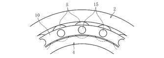
- reference numeral 15 denotes a welded portion.
- the difference (diameter difference) between the diameter dimension (diameter dimension) of the small end face 5a and the diameter dimension (diameter dimension) of the large end face 5b is relatively large. It is getting bigger. For this reason, when the tapered roller 5 is assembled, the tapered roller 5 is not assembled in a posture (direction) opposite to the normal posture (direction). That is, the regular direction of the tapered roller 5 is as shown in FIG.
- the small end surface 5 a side is the direction in which the small ring surface of the inner ring 4 is arranged.
- the difference in diameter between the small end surface 5a and the large end surface 5b is small, and the small end surface 5a and the large end surface 5b are ground and difficult to distinguish from the appearance.
- the difference in diameter between the small end surface 5a and the large end surface 5b is small, it can be assembled as shown in FIG.
- a cage having a pocket is not used, so that the tapered roller 5 is not fitted into the pocket when assembled, and the tapered roller is in the reverse direction.
- it can be assembled without knowing that it is in the opposite direction.
- the tapered roller 5 when assembled in a posture (direction) opposite to the normal posture (direction), the tapered roller 5 may be peeled off or damaged, or the shaft member or the like cannot be rotated smoothly as a bearing. . Further, in a tapered roller bearing used for facilities or the like where a heavy load or impact load acts, the number of rollers used for one bearing is large, for example, 50 / bearing, and human error is likely to occur.
- one rolling element (roller) is inserted into each pin of the cage, and the elastic force of each pin is utilized to push it into the inner ring.
- Patent Document 2 a desired surface is provided on the inner peripheral surface of the through hole of one annular member (first ring) through which the pin is inserted and the outer peripheral surface of the through hole arrangement portion of the pin arranged in the through hole.
- the cage is such that a pillar portion is disposed between rollers adjacent to each other in the circumferential direction. That is, in Patent Document 3, the cage has a plurality of divided segments arranged along the circumferential direction, and a pocket into which the roller is inserted is formed in each divided segment. For this reason, a pillar part is arrange
- the present invention provides a tapered roller bearing capable of stably incorporating a roller having a small diameter difference between a small end surface and a large end surface in a normal direction.
- the tapered roller bearing of the present invention includes an outer ring having a raceway surface on the inner periphery, an inner ring having a raceway surface on the outer periphery, a plurality of tapered rollers disposed between the outer ring raceway ring and the inner ring raceway ring,
- the tapered roller has a diameter difference of 2 mm or less, which is a difference between the diameter of the small end face and the diameter of the large end face, and has a through hole extending along the axial direction in the axis.
- a hollow roller formed, and the cage includes a pair of annular members disposed on the small end face side and the large end face side of the tapered roller, and a pair of annular members inserted into the through holes of the tapered roller.
- a tapered roller bearing having a pin member to be connected, and only when the tapered roller is arranged in a normal direction, the pin member can be inserted into the through hole of the tapered roller so that the pin member can be attached to the cage. It has a regulatory structure.
- the tapered roller is disposed in a normal direction with respect to the inner ring, that is, the large end surface of the tapered roller faces the large collar of the inner ring, and the small end surface of the tapered roller is the inner ring.
- the pin member is inserted into the through hole of the tapered roller without being restricted by the restriction structure, and the pin member to the cage is inserted. Installation can be performed.
- annular member is arranged on the small end face side of the tapered roller, an annular member is arranged on the large end face side of the tapered roller, or a pin member is inserted into the through hole of the tapered roller. It becomes a process to do.
- the tapered roller is not arranged in the normal direction with respect to the inner ring, that is, the tapered roller small end surface faces the inner ring collar, and the tapered roller large end surface faces the inner ring collar. If the cage is properly assembled in the facing state, it is restricted by the regulation structure, and the pin member cannot be inserted into the through hole of the tapered roller, so that the pin member is attached to the cage. I can't do it.
- the restriction structure is configured by the concave / convex fitting structure
- the concave / convex fitting structure is fitted when the cage is properly assembled in a state where the tapered rollers are arranged in the normal direction with respect to the inner ring.
- the pin member can be inserted into the through hole of the tapered roller and attached to the cage.
- the regular assembly process of the cage is performed in a state where the tapered rollers are not arranged in the regular direction with respect to the inner ring, the concave-convex fitting structure is not in a fitted state, and the through hole of the tapered roller Therefore, the pin member cannot be inserted through the holder, and the pin member cannot be attached to the cage.
- a roller side fitting part consisting of a concave part or a convex part is provided on either the small end face or the large end face of the tapered roller, and the convex part or concave part fitting on the roller side fitting part is provided on the cage side. It is preferable that a cage-side fitting portion is provided, and the roller-side fitting portion and the cage-side fitting portion constitute the uneven fitting structure.
- a roller side fitting portion made of a concave portion is provided on one side of the small end surface and the large end surface of the tapered roller, and the roller corresponding surface of the annular member facing the roller side fitting portion is provided with a roller.
- a cage side fitting portion comprising a convex portion to be fitted to the side fitting portion can be provided.
- a roller side fitting portion formed of a concave portion is provided on either one of the small end surface and the large end surface of the tapered roller, and the retainer side fitting portion is a washer that is externally fitted to the pin member.
- the retainer side fitting portion is a washer that is externally fitted to the pin member.
- a roller side fitting part consisting of a convex part is provided on one side of either the small end face or the large end face of the tapered roller, and the roller side fitting is performed on the roller corresponding surface of the annular member facing the roller side fitting part.
- the cage side fitting part which consists of a recessed part fitted to a part may be provided.
- the cage-side fitting portion may be constituted by a bush fitted on the pin member.
- a bush that is externally fitted to the pin member is fitted to the large chamfered portion that is the roller side fitting portion, and the cage Assembly becomes possible.
- the cage cannot be assembled corresponding to the chamfered portion where the bush is small.
- Chamfered portions are provided at both openings of the through hole of the tapered roller, and the chamfered portion on the small end surface side and the chamfered portion on the large end surface side are made different from each other.
- the hole diameter on the small end face side and the hole diameter on the large end face side are made different, and the outer shape of the pin member inserted into the through hole corresponds to the hole shape of the through hole. It may have a shape and allow the pin member to be inserted into the through hole only in one direction on either the small end face side or the large end face side.
- the pin member can be set so as not to be inserted even if the pin member is inserted from the normal direction.
- the tapered roller has a through-hole having a large-diameter hole portion and a small-diameter hole portion
- the pin member has a pin member main body having a large-diameter shaft portion and a small-diameter shaft portion.
- a pair of annular members may be connected to each other in a state where the small diameter shaft portion side of the pin member main body of the member is inserted.
- the small diameter shaft portion side of the pin member body of the pin member is inserted through the large diameter hole portion of the through hole, first, the small diameter shaft portion of the pin member body passes through the large diameter hole portion of the through hole, Thereafter, the large-diameter shaft portion of the pin member main body is inserted into the large-diameter hole portion of the through hole, and the pin member can be penetrated into the through-hole.
- the small diameter shaft portion side of the pin member is inserted through the small diameter hole portion of the through hole, the small diameter shaft portion of the pin member is first inserted into the small diameter hole portion of the through hole, and then the large diameter shaft Although it is necessary for the portion to pass through the small diameter hole portion, the large diameter shaft portion cannot be inserted into the small diameter hole portion.
- the through hole of the tapered roller has a large diameter hole portion and a small diameter hole portion
- it can be set so that the large diameter hole portion of the through hole of the tapered roller is disposed on the inner ring small diameter side.
- the pin member is inserted from the inner ring small diameter side.
- the through hole of the tapered roller is a tapered hole whose hole diameter changes along the axial direction
- the pin member has a tapered pin member main body whose outer diameter changes along the axial direction.
- the pair of annular members may be connected to each other in a state where the small diameter side of the pin member main body of the pin member is inserted from the large diameter side opening of the through hole.
- the pin member having the tapered pin member main body can be inserted through the through hole.
- the direction of the tapered roller is opposite to the normal direction, if the pin member is inserted in the direction with respect to the normal direction roller, it is inserted from the opening on the small diameter side of the through hole. Will do.
- pin members whose diameter gradually increases from the distal end side toward the proximal end side are inserted into the through holes whose diameter increases sequentially from the insertion side toward the outlet side. For this reason, the pin member is caught in the through hole during insertion and cannot be inserted.
- the pin member when the tapered roller is arranged in the direction opposite to the normal direction, the pin member can be set not to be inserted even if it is attempted to be inserted from the normal direction. For this reason, it can be grasped that the tapered rollers that cannot be inserted are arranged in the direction opposite to the normal direction, and the reverse mounting of the tapered rollers can be avoided.
- the tapered roller even if the diameter difference between the diameter of the small end face and the diameter of the large end face is as small as 2 mm or less, and the small end face and the large end face are difficult to distinguish from the appearance, the tapered roller is not assembled in the reverse direction. Tapered roller bearings can be assembled with high quality, and the bearing function can be demonstrated stably over a long period of time.
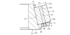
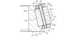
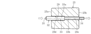
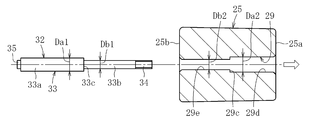
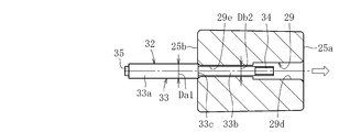
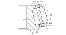
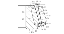
- FIG. 2 is a cross-sectional view of a main part in a state where the first tapered roller bearing shown in FIG. 1 is assembled and the tapered roller is sandwiched between a pair of annular members. It is sectional drawing of the state which showed the assembly method of the 1st taper roller bearing shown in FIG. 1, and equipped with the pin member. It is principal part sectional drawing of the 1st tapered roller bearing of the state in which the tapered roller of the reverse direction and the normal direction was assembled
- FIG. 14 is an essential part cross-sectional view showing a method of assembling the tapered roller bearing shown in FIG. 13, with the tapered rollers sandwiched between a pair of annular members. It is sectional drawing of the state which showed the assembly method of the tapered roller bearing shown in FIG. 13, and equipped with the pin member.
- FIG. 14 is a cross-sectional view showing a relationship between the tapered roller and the pin member shown in FIG. 13 and in a state in which the pin member is inserted in a normal direction with respect to a roller opposite to the normal direction.
- FIG. 18 is an essential part cross-sectional view of the tapered roller bearing shown in FIG. 17 before assembling the pin member.
- FIG. 18 is a cross-sectional view of a main part in a state where the tapered roller bearing shown in FIG.
- FIG. 18 is a cross-sectional view showing a method of assembling the tapered roller bearing shown in FIG. 17 and with a pin member mounted.
- FIG. 18 is a cross-sectional view showing a relationship between the tapered roller and the pin member shown in FIG. 17 and in a state where the pin member is arranged in the normal direction with respect to the normal-direction roller. It is sectional drawing of the state in the middle of inserting the pin member in the normal direction with respect to the roller of a normal direction, showing the relationship between the tapered roller and the pin member shown in FIG.
- FIG. 18 is a cross-sectional view illustrating a relationship between the tapered roller and the pin member illustrated in FIG.
- FIG. 18 is a cross-sectional view showing a relationship between the tapered roller and the pin member shown in FIG. 17 and in a state where the pin member is arranged in the normal direction with respect to the roller opposite to the normal direction.
- FIG. 18 is a cross-sectional view showing a relationship between the tapered roller and the pin member shown in FIG. 17 and in the middle of inserting the pin member in the normal direction with respect to the roller opposite to the normal direction. It is principal part sectional drawing of the bearing of the state where the roller has been arrange
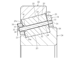
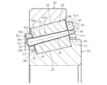
- FIG. 1 shows a tapered roller bearing according to the first embodiment.
- the tapered roller bearing includes an outer ring 22 having a raceway surface 21 on the inner periphery, an inner ring 24 having a raceway surface 23 on the outer periphery, and a raceway surface 21 of the outer ring 22.
- a plurality of tapered rollers 25 disposed between the raceway surface 23 of the inner ring 24 and a cage 26 that holds the tapered rollers 25.
- the inner ring 24 has a small collar 27 formed on the small diameter side of the raceway surface 23 and a large collar 28 formed on the large diameter side. That is, a thrust load is received by the large brim 28 and the tapered roller 25 is prevented from falling off by the small brim 27.
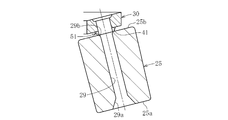
- the tapered roller 25 has a relatively small difference between the diameter of the small end face 25a and the diameter of the large end face 25b. That is, as shown in FIG. 2A, when the diameter of the small end surface 25a is Da and the diameter Db of the large end surface 25b is set to (Db ⁇ Da) ⁇ 2 (mm).
- the tapered roller 25 is a hollow roller in which a through-hole 29 extending along the axial direction is formed in the axial center.
- Chamfered portions 29 a and 29 b are provided in the small end surface side opening and the large end surface side opening of the through hole 29, respectively.
- the chamfered portion 29a on the small end surface 25a side is set larger than the chamfered portion 29b on the large end surface 25b side.
- the chamfered portion 29 a on the large side is a tapered hole that expands from the inside of the through hole 29 toward the small end surface 25 a
- the chamfered portion 29 b on the small side is an opening on the large end surface side of the through hole 29. It is comprised from the round part provided in a part.
- the cage 26 is inserted into the pair of annular members 30 and 31 disposed on the small end surface 25 a side and the large end surface 25 b side of the tapered roller 25 and the through hole 29 of the tapered roller 25 and is paired with the pair of annular members 30 and 31.
- the pin member 32 has a pin member main body 33 whose shaft diameter is slightly smaller than the inner diameter of the through-hole 29, a male screw portion 34 connected to the tip of the pin member main body 33, and a base of the pin member main body 33.
- the head 35 is provided at the end.
- the annular member 30 is provided with a plurality of through holes 36 at an equal pitch along the circumferential direction.
- the annular member 30 is arranged so as to face the small end surface 25a, so that the inner end surface 30a and the outer end surface 30b are predetermined with respect to a plane orthogonal to the bearing axis.
- the inner surface 30c and the outer surface 30d are inclined at an angle, and are cylindrical surfaces centered on the shaft center of the bearing.
- the inner diameter of the through hole 36 is set larger than the shaft diameter of the pin member main body 33 of the pin member 32.
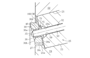
- a short cylindrical bush 40 is mounted in the through hole 36, and a counterbore portion 36a is provided in the opening of the through hole 36 on the outer end surface 30b side.
- a part of the bush 40 protrudes toward the tapered roller 25 side from the inner end surface 30 a of the annular member 30. For this reason, as shown in FIG. 1, in a state where the tapered rollers 25 are arranged and assembled in the normal direction, the protruding portion 40 a of the bush 40 toward the tapered rollers 25 side is loosened by the large chamfered portion 29 a of the tapered rollers 25.
- the state in which the tapered roller 25 is arranged in the normal direction means that the large end surface 25 b of the tapered roller 25 faces the large collar 28 of the inner ring 24 and the small end surface 25 a of the tapered roller 25 is in contact with the inner ring 24. It is in a state facing the small brim 27.
- the large chamfered portion 29a of the tapered roller 25 becomes the roller side fitting portion 50 made of a concave portion, and the protruding portion 40a of the bush 40 fits on the roller side fitting portion made of this concave portion. It becomes the joint part 51.
- the roller-side fitting portion 50 and the cage-side fitting portion 51 constitute an uneven fitting structure M, and this uneven fitting structure M is such that the tapered rollers 25 are arranged in the normal direction with respect to the inner ring 24. In the state, the cage 26 is fitted only in the assembly in the normal direction. For this reason. With this uneven fitting structure M, the pin member 32 can be inserted into the through hole 29 of the tapered roller 25 and the pin member 32 can be attached to the cage 26 only when the tapered roller 25 is arranged in the normal direction. A regulation structure 100 is formed.
- the annular member 31 is provided with a plurality of screw holes 37 at an equal pitch along the circumferential direction (the same pitch as the arrangement pitch of the through holes 36 of the annular member 30).
- the annular member 31 is disposed so as to face the large end surface 25b, so that the inner end surface 31a and the outer end surface 31b are perpendicular to the bearing axis.
- the inner surface 31c and the outer surface 31d are inclined at a predetermined angle, and are cylindrical surfaces centered on the axis of the bearing.
- the screw hole 37 is disposed on the axis of the through hole 29 of the tapered roller 25.
- the large-diameter side end surface 24a of the inner ring 24 is directed downward, and the annular member 31 (the annular member 31 having the screw hole 37) is fitted to the raceway surface 21 of the inner ring 24.
- the tapered rollers 25 are arranged so as to face the large end surface 25b.
- the annular member 31 is received by a receiving member (jig) (not shown).
- one annular member 30 is disposed on the small end surface 25 a of the tapered roller 25.
- the male screw portion 34 at the tip of the pin member 32 is inserted into the through hole 29 of the tapered roller 25 through the through hole 36 of the annular member 30. That is, the pin member 32 is inserted into the through hole 29 along the axis of the tapered roller 25.
- the male screw portion 34 of the pin member 32 is screwed into the screw hole 37 of the annular member 31. As shown in FIG. 2C, it can be screwed.
- the head 35 of the pin member 32 is used for this screwing.
- the base portion of the pin member 32 (the head 35 side of the pin member main body 33) is annular. It is in a state of being fitted loosely into the through hole 36 of the member 30. Therefore, the head member 35 and its vicinity are welded to fix the pin member 32 to the annular member 30.
- the bush 40 that is externally fitted to the pin member 32 is fitted into the through hole 36 of the annular member 30.
- the annular member 30 in which the bush 40 is inserted into the through hole 36 of the annular member 30 is arranged as shown in FIG. 2B, and then the pin member 32 is inserted into the through hole 29 of the tapered roller 25.
- the bush 40 is inserted into the through hole 36 of the annular member 30, and the pin member 32 is inserted into the through hole 29 of the tapered roller 25.
- the pin member 32 may be inserted into the through hole 29 of the tapered roller 25, and then the bush 40 may be fitted into the through hole 36 of the annular member 30.
- the protruding portion 40a of the bush 40 toward the tapered roller 25 side has a large chamfer as shown in FIG. It will be inserted into the part 29a in a loose fit.
- the protruding portion 40a of the bush 40 bites into the small chamfered portion 29b of the large end surface 25b, and the track of the outer ring 22
- the rolling surface (outer diameter surface) of the tapered roller 25 is pressed against the small diameter side of the surface 21 and the small diameter side of the raceway surface 23 of the inner ring 24.
- the state in which the tapered roller 25 is disposed in the direction opposite to the normal direction is that the small end surface 25 a of the tapered roller 25 faces the large collar 28 of the inner ring 24, and the large end surface 25 b of the tapered roller 25 is small in the inner ring 24. It is in a state of facing the collar 27.
- the regular assembly process is a process shown in FIGS. 2A to 2C, in which the annular member 30 is disposed on the small end face side of the tapered roller 25, or the annular member 31 is disposed on the large end face side of the tapered roller 25. This is a step of arranging or inserting the pin member 32 through the through hole 29 of the tapered roller 25.
- the tapered roller 25 is arrange
- the cage-side fitting portion 51 cannot be fitted to the roller-side fitting portion 50 if the cage is properly assembled.
- the tapered rollers 25 that cannot be fitted are arranged in the direction opposite to the normal direction, and the incorporation of the tapered rollers 25 in the reverse direction can be avoided.
- the tapered roller bearing can be assembled with high quality without being assembled in the opposite direction, and the bearing function can be exhibited stably over a long period of time.
- the roller side fitting portion 50 can be formed by the chamfered portion 29 a of the tapered roller 25, and the cage side fitting portion 51 is fitted into the through hole 36 of the annular member 30.
- the concave / convex fitting structure M can be provided with a simple configuration with a small number of parts.
- the tapered roller 25 is similar to the tapered roller 25 shown in FIG. Chamfered portions 29a and 29b are respectively provided in the end surface side openings.
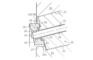
- a flat conical trapezoidal convex portion 41 as shown in FIG. 6 is provided on the inner end surface 30a of the annular member 30. That is, as shown in FIG. 5, when the tapered roller 25 is arranged in the normal direction, as shown in FIG. 7, the convex portion 41 is fitted into the chamfered portion 29a in a loose fit. That is, the chamfered portion 29a constitutes the roller-side fitting portion 50, and the convex portion 41 constitutes the cage-side fitting portion 51 that fits into the roller-side fitting portion 50 formed of the chamfered portion 29a.
- the convex portion 41 on the annular member 30 side is fitted into the large chamfered portion 29a of the tapered roller 25 in a loose manner as described above.
- the convex portion 41 comes into contact with the chamfered portion 29b on the large end surface 25b side of the tapered roller 25 as shown in FIG.
- the annular member 30 cannot be disposed.
- the tapered roller bearing shown in FIG. 5 and the like since the concave and convex fitting structure M including the roller-side fitting portion 50 and the cage-side fitting portion 51 is provided, the tapered roller has a direction opposite to the normal direction. When arranged, the roller side fitting portion 50 cannot be fitted to the cage side fitting portion 51.
- the cage-side fitting portion 51 is provided by the convex portion 41 provided on the annular member 30, and the convex portion 41 and the cage-side fitting portion 51 can be integrated to improve assemblability. . That is, in the tapered roller bearing shown in FIG. 5 and the like, the restriction structure 100 is configured by the concave-convex fitting structure M including the roller-side fitting portion 50 and the cage-side fitting portion 51.
- a ring-shaped convex portion 42 is provided at the center of the small end surface 25a of the tapered roller 25, and the annular member 30 is provided.
- a circular concave portion 43 into which the convex portion 42 is fitted is provided at the central portion of the inner diameter surface of the first concave portion.
- the Nusumi part 44 is provided in the base part of the convex part 42.
- the convex portion 42 is fitted (fitted) into the concave portion 43 in a loose fit.
- the concave portion 43 of the annular member 30 corresponds to the large end surface 25b having no concave portion of the tapered roller 25 as shown in FIG.
- the cage cannot be assembled.
- the convex part 42 of the small end surface 25 a of the roller 25 constitutes the roller side fitting part 50
- the concave part 43 of the annular member 30 constitutes the cage side fitting part 51.
- the tapered roller bearings shown in FIGS. 9 and 10 also have a concave-convex fitting structure M composed of a roller-side fitting portion 50 and a cage-side fitting portion 51, that is, a regulating structure 100, and is in a direction opposite to the normal direction.
- the roller-side fitting portion 50 cannot be fitted with the cage-side fitting portion 51, and the tapered roller can be avoided from being assembled in a reverse orientation.
- the convex portion 42 is provided on the small end surface 5a, the posture of the tapered roller 25 can be grasped also by the appearance.
- the washer 46 of the cage side fitting portion 51 is used, the configuration of the cage side fitting portion 51 can be simplified and the cost can be reduced.
- a recess 45 is provided in the large end surface 25 b of the tapered roller 25, and a ring that is externally fitted to the pin member 32 in the recess 45.
- a body (washer) 46 is fitted.
- the concave portion 45 of the large end surface 25 b of the tapered roller 25 constitutes the roller side fitting portion 50
- the retainer side fitting portion 51 is constituted by the washer 46. That is, the concave and convex fitting structure M is configured by the concave portion 45 and the washer 46.
- the washer 46 can be fitted into the recess 45 as shown in FIG.
- the concave portion 45 of the large end surface 25 b of the tapered roller 25 is disposed on the annular member 30 side having the through hole 36.
- the washer 46 disposed on the male screw portion 34 side of the pin member 32 cannot be fitted into the concave portion 45 of the large end surface 25 b of the tapered roller 25.
- the tapered roller bearing shown in FIG. 12 is provided with the concave-convex fitting structure M composed of the roller-side fitting portion 50 and the cage-side fitting portion 51, that is, the restriction structure 100, the direction opposite to the normal direction.
- the tapered roller 25 is disposed on the roller side fitting portion 50, the cage side fitting portion 51 cannot be fitted into the roller side fitting portion 50. That is, even if it is what is shown in this FIG. 12, the uneven
- this washer 46 when assembling, it will mount on this annular member 31 in the state shown to FIG. 2A.
- the concave portion 45 of the large end surface 25 b of the tapered roller 25 constitutes the roller side fitting portion 50, and the retainer side fitting portion 51 is constituted by the washer 46. For this reason, the posture of the tapered roller 25 can be grasped by the concave portion 45 of the large end surface 25 b of the tapered roller 25.
- the tapered roller bearing of the second embodiment shown in FIG. 6, the tapered roller bearing of the third embodiment shown in FIG. 9, and the tapered roller bearing of the fourth embodiment shown in FIG. the same effect as the tapered roller bearing shown in FIG. That is, as the roller side fitting part 50, it can be comprised by the recessed part or convex part provided in either one side of the small end surface 25a and the large end surface 25b of the tapered roller 25, and as the cage side fitting part 51, It can comprise by the convex part or recessed part which fits the said roller side fitting part 50 in a cage
- FIG. 13 shows a tapered roller bearing according to the fifth embodiment.
- This tapered roller bearing also has an outer ring 22 having a raceway surface 21 on the inner periphery, an inner ring 24 having a raceway surface 23 on the outer periphery, and a raceway surface 21 of the outer ring 22.
- a plurality of tapered rollers 25 disposed between the raceway surface 23 of the inner ring 24 and a cage 26 that holds the tapered rollers 25.
- the inner ring 24 has a small collar 27 formed on the small diameter side of the raceway surface 23 and a large collar 28 formed on the large diameter side. That is, a thrust load is received by the large brim 28 and the tapered roller 25 is prevented from falling off by the small brim 27.
- the tapered roller 25 has a relatively small difference between the diameter of the small end face 25a and the diameter of the large end face 25b. That is, as shown in FIG. 15A, when the diameter of the small end face 25a is Da and the diameter Db of the large end face 25b is set to (Db ⁇ Da) ⁇ 2 (mm).
- the tapered roller 25 is a hollow roller in which a through-hole 29 extending along the axial direction is formed in the axial center.
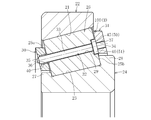
- the through hole 29 includes a large diameter hole portion 29d on the small end surface 25a side and a small diameter hole portion 29e on the large end surface 25b side.
- a step portion 29 c between the large diameter hole portion 29 d and the small diameter hole portion 29 e is located at a substantially intermediate portion in the axial direction of the tapered roller 25. That is, the axial length of the large diameter hole portion 29d and the axial length of the small diameter hole portion 29e are set to be substantially the same.
- the cage 26 is inserted into the pair of annular members 30 and 31 disposed on the small end surface 25 a side and the large end surface 25 b side of the tapered roller 25 and the through hole 29 of the tapered roller 25 and is paired with the pair of annular members 30 and 31. And a pin member 32 for connecting the two to each other.
- the pin member 32 includes a pin member main body 33 composed of a large-diameter shaft portion 33a on the base side and a small-diameter shaft portion 33b on the tip portion side, and a male connected to the tip of the small-diameter shaft portion 33b of the pin member main body 33. And a threaded portion 34.
- the outer diameter of the male screw portion 34 and the outer diameter of the small-diameter shaft portion 33b are set to be the same.
- a head portion 35 is connected to the outer end surface of the large diameter shaft portion 33 a of the pin member main body 33.
- the outer diameter Da1 of the large-diameter shaft portion 33a is set slightly smaller than the inner-diameter size Da2 of the large-diameter hole portion 29d of the through hole 29 of the roller 25, and the outer diameter of the small-diameter shaft portion 33b.
- the dimension Db1 is set slightly smaller than the inner diameter dimension Db2 of the small diameter hole portion 29e of the through hole 29 of the roller 25. That is, Da1 ⁇ Da2 and Db1 ⁇ Db2.
- the inner diameter Db2 of the small diameter hole portion 25b of the through hole 29 needs to be set smaller than the outer diameter dimension Da1 of the large diameter shaft portion 33a, and Db2 ⁇ Da1.
- the annular member 30 is provided with a plurality of through holes 36 at an equal pitch along the circumferential direction.
- the annular member 30 is arranged so as to face the small end surface 25a, so that the inner end surface 30a and the outer end surface 30b are predetermined with respect to a plane perpendicular to the bearing axis.
- the inner surface 30c and the outer surface 30d are inclined at an angle, and are cylindrical surfaces centered on the shaft center of the bearing.
- the annular member 31 is provided with a plurality of screw holes 37 at an equal pitch along the circumferential direction (the same pitch as the arrangement pitch of the through holes 36 of the annular member 30).
- the annular member 31 is disposed so as to face the large end surface 25b, so that the inner end surface 31a and the outer end surface 31b are perpendicular to the bearing axis.
- the inner surface 31c and the outer surface 31d are inclined at a predetermined angle, and are cylindrical surfaces centered on the axis of the bearing.
- the screw hole 37 is disposed on the axis of the through hole 29 of the roller.
- the large-diameter side end surface 24a of the inner ring 24 is directed downward, and the annular member 31 (the annular member 31 having the screw hole 37) is fitted to the raceway surface 21 of the inner ring 24.
- the tapered rollers 25 are arranged so as to face the large end surface 25b.
- the annular member 31 is received by a receiving member (jig) (not shown).
- the large diameter hole portion 29d of the through hole 29 is positioned on the upper side, and the small diameter hole portion 29e of the through hole 29 is disposed on the lower side.
- one annular member 30 is disposed on the small end surface 25 a of the tapered roller 25.
- the male screw portion 34 at the tip of the pin member 32 is inserted into the through hole 29 of the tapered roller 25 through the through hole 36 of the annular member 30. That is, as shown in FIG. 15A, the pin member 32 is inserted into the through hole 29 as indicated by the arrow along the axis of the tapered roller 25.
- the male screw portion 34 to the small diameter shaft portion 33 b of the pin member 32 enter the small diameter hole portion 29 e of the through hole 29 via the large diameter hole portion 29 d of the through hole 29.
- the small diameter shaft portion 33b of the pin member 32 corresponds to the small diameter hole portion 29e of the through hole 29 and the pin is connected to the large diameter hole portion 29d of the through hole 29.
- the large-diameter hole 29d of the member 32 can be brought into a corresponding state. This is because Da1 ⁇ Da2 and Db1 ⁇ Db2 are set as shown in FIG. 15A.
- the bush 52 is fitted into the through hole 36, and the head 35 or the vicinity thereof is welded to fix the annular member 30.
- the annular member 30 may be set in a state where the bush 52 is fitted (attached) to the through hole 36, and then the pin member 32 may be inserted into the through hole 29. Further, such a bush 52 may be omitted.
- a unit body in which the tapered rollers 25 held by the cage 26 are mounted on the inner ring 24 is configured. By assembling this unit body and the outer ring 22, the tapered roller bearing shown in FIG. 13 can be assembled.
- the pin member 32 can be inserted into the through hole 29 of the tapered roller 25 from the normal direction.
- the state in which the tapered roller 25 is arranged in the normal direction means that the large end surface 25 b of the tapered roller 25 faces the large collar 28 of the inner ring 24 and the small end surface 25 a of the tapered roller 25 is in contact with the inner ring 24. It is in a state facing the small brim 27.
- the insertion of the pin member 32 into the through hole 29 of the tapered roller 25 from the normal direction means that the pin member 32 is inserted from the small diameter side of the inner ring 24 along the axial direction of the through hole 29 of the tapered roller 25. Is to insert into.
- the pin member 32 can be inserted into the through hole 29 of the tapered roller 25 from the normal direction.
- the pin member 32 cannot be inserted into the through hole 29 of the tapered roller from the normal direction.
- the tapered roller 25 is disposed in the direction opposite to the normal direction.
- the small end surface 25 a of the tapered roller 25 faces the large collar 28 of the inner ring 24, and the large end surface 25 b of the tapered roller 25 is small in the inner ring 24. It is in a state of facing the collar 27. In this state, when the pin member 32 is inserted into the through hole 29 of the tapered roller from the normal direction, the pin member 32 is inserted into the through hole 29 from the state shown in FIG. 16A.
- the large end face 25b faces the pin member 32 side, and the small-diameter hole portion 29e of the through hole 29 is arranged on the pin member 32 side.
- the small diameter shaft portion 33b of the pin member 32 is inserted up to the small diameter hole portion 29e of the through hole 29 as shown in FIG. be able to.
- the outer diameter dimension of the large-diameter shaft portion 33a of the pin member 32 is Da1 and the inner diameter dimension of the small-diameter hole portion 29e of the through hole 29 is Db2
- Da1> Db2 is set, and therefore, as shown in FIG. 16B.
- the stepped portion (stepped portion) 33c between the large diameter shaft portion 33a and the small diameter shaft portion 33b of the pin member 32 comes into contact with the large end surface side opening edge of the small diameter hole portion 29e of the through hole 29. No more can be inserted in the direction of the arrow. For this reason, if the tapered roller 25 is arrange
- the tapered roller 25 shown in FIG. 13 when the tapered roller 25 shown in FIG. 13 is arranged in the direction opposite to the normal direction, the pin member 32 cannot be inserted from the normal direction. Therefore, it can be grasped that the tapered roller 25 that cannot be inserted is arranged in the direction opposite to the normal direction, and the reverse mounting of the tapered roller 25 can be avoided.
- the diameter difference (Db ⁇ Da) between the diameter of the small end face 25a and the diameter of the large end face 25b is as small as 2 mm or less and the small end face 25a and the large end face 25b are difficult to distinguish from each other,
- the tapered roller bearing can be assembled with high quality without being assembled in the opposite direction, and the bearing function can be exhibited stably over a long period of time.
- the restriction structure 100 is configured by adopting a shape corresponding to the hole shape of the through hole 29.
- the through hole 29 of the tapered roller 25 is composed of a large diameter hole portion 29d and a small diameter hole portion 29e
- the pin member main body 33 of the pin member 32 has a small diameter shaft portion 33b and a large diameter shaft portion 33a. It is said.
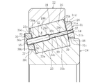
- FIG. 17 shows a sixth embodiment, and the through hole 29 of the tapered roller 25 in this case is a tapered hole 54 whose hole diameter changes along the axial direction. Specifically, the diameter gradually decreases along the axial direction from the small end face 25a side to the large end face 25b, and the opening on the small end face 25a side has a larger diameter than the opening on the large end face 25b. .
- the pin member 32 also has a tapered pin member body 53 whose outer diameter changes along the axial direction.
- the pin member main body 53 of the pin member 32 is a taper shaft whose outer diameter is gradually reduced from the head 35 to the male screw portion 34, and the head 35 side is larger than the male screw portion 34. It is the diameter.
- the maximum outer diameter of the pin member main body 53 is Da3
- the maximum inner diameter of the tapered hole 54 is Db3
- the minimum outer diameter of the pin member main body 53 (the outer diameter dimension of the male screw) is Da4.
- the minimum inner diameter of the tapered hole 54 is Db4, Da3 ⁇ Db3, Da4 ⁇ Db4, and Db4 ⁇ Da3.
- the outer diameter of the axial intermediate portion of the pin member main body 53 is Da5 and the inner diameter of the axial intermediate portion of the tapered hole 54 is Db5, Da5 ⁇ Db5 and Db5 ⁇ Da3. It is said.
- the taper angle of the taper hole 54 and the taper angle of the pin member main body 53 are substantially the same.
- the other configuration of the tapered roller bearing shown in FIG. 17 is the same as the configuration of the tapered roller bearing shown in FIG. 13. Therefore, the same members are denoted by the same reference numerals in FIG. Omitted.
- FIG. 18 shows an assembly method of the tapered roller bearing shown in FIG.
- This assembling method is the same as the assembling method shown in FIG. That is, as shown in FIG. 18A, the large-diameter end surface 24a of the inner ring 24 is directed downward, and the annular member 31 (the annular member 31 having the screw hole 37) is fitted to the raceway surface 21 of the inner ring 24. It arrange
- jig receiving member
- the annular member 30 is disposed on the small end surface 25 a of the tapered roller 25.
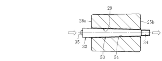
- the male screw portion 34 at the tip of the pin member 32 is inserted into the through hole 29 of the tapered roller 25 through the through hole 36 of the annular member 30. That is, as shown in FIG. 19A, the pin member 32 is inserted into the through hole 29 along the axis of the tapered roller 25 as indicated by an arrow.
- the male screw portion 34 or the tapered pin member main body 53 of the pin member 32 enters the through hole 29 through the large diameter side opening of the through hole 29 as shown in FIG.
- the tapered pin member main body 53 can be inserted into the through hole 29 as shown in FIG. 19C. This is because Da3 ⁇ Db3, Da4 ⁇ Db4, Db4 ⁇ Da3, Da5 ⁇ Db5, and Db5 ⁇ Da3.
- the male threaded portion 34 of the pin member 32 protrudes from the through hole 29 of the tapered roller 25 and the male threaded portion 34 of the pin member 32 is screwed into the threaded hole 37 of the annular member 31. As shown in FIG. 18C, it can be screwed. The head 35 of the pin member 32 is used for this screwing. Then, as shown in FIG. 18C, in a state where the male screw portion 34 of the pin member 32 is screwed into the screw hole 37 of the annular member 31, the base portion (anti-small-diameter shaft portion side) of the pin member main body 53 of the pin member 32 is. It is in a state of being fitted in the through hole 36 of the annular member 30 in a loose fit.
- the bush 52 is fitted into the through hole 36 and the head 35 or the vicinity thereof is welded to fix the pin member 32 to the annular member 30.
- the annular member 30 may be set in a state where the bush 52 is fitted (attached) to the through hole 36, and then the pin member 32 may be inserted into the through hole 29. Further, such a bush 52 may be omitted.
- a tapered roller bearing shown in FIG. 17 can be assembled by assembling the unit body and the outer ring 22.
- the pin member 32 can be inserted into the through hole 29 of the tapered roller from the normal direction.
- the pin member 32 cannot be inserted into the through hole 29 of the tapered roller 25 from the normal direction.
- the tapered roller 25 is disposed in the direction opposite to the normal direction.
- the small end surface 25 a of the tapered roller 25 faces the large collar 28 of the inner ring 24, and the large end surface 25 b of the tapered roller 25 is small in the inner ring 24. It is in a state of facing the collar 27. In this state, when the pin member 32 is inserted into the through hole 29 of the tapered roller from the normal direction, the pin member 32 is inserted into the through hole 29 from the state shown in FIG. 20A.
- the large end surface 25b faces the pin member 32 side, and the small diameter side of the through hole 29 is arranged on the pin member 32 side.
- the pin member 32 is inserted as shown by an arrow from the state shown in FIG. 20A, a part of the pin member main body 53 side of the pin member 32 on the male screw portion 34 side is a tapered hole as shown in FIG. 20B. 54 can be inserted into the opening on the large end face side.
- the hole diameter on the small end face side is different from the hole diameter on the large end face side, and the outer shape of the pin member 32 inserted into the through hole 29 is changed to the hole shape of the through hole 29.
- the restriction structure 100 is configured by adopting a corresponding shape.
- the through hole 29 of the tapered roller 25 is a tapered hole 54 and the pin member 32 has a tapered pin member main body 53.
- the tapered roller 25 having the through hole 29 including the small diameter hole portion 29e and the large diameter hole portion 29d as shown in FIG. 13 is tapered as shown in FIG.
- the tapered roller 25 having the through hole 29 including the hole 54 may be used. That is, the hole diameter on the small end face 25a side and the hole diameter on the large end face 25b side are made different, and the outer shape of the pin member 32 inserted into the through hole 29 may be a shape corresponding to the hole shape of the through hole 29.
- the roller 25 is excellent in design and productivity.
- the roller side fitting portion 50 is provided with the cage side fitting portion 51.
- the cage side fitting portion 51 cannot be fitted to the roller side fitting portion 50. I just need it.
- the concave-convex fitting structure M is composed of a convex portion formed on the small end surface 25 a of the roller 25 and a concave portion formed on the inner end surface 30 a of the annular member 30, Even if the concave portion of the inner end face 30a is a circular hole in the member 30, and a plurality of small protrusions are arranged at a predetermined pitch along the circumferential direction without forming a ring shape as a convex portion to be fitted to the concave portion. Good.
- the outer shape of the convex portion and the inner shape of the concave portion are not limited to a circular shape, and can be variously changed within a range that does not impair the rotational motion when incorporated.
- the annular member 30 may have recesses in the inner end surface 30 a that open to the inner and outer diameter surfaces of the annular member 30.
- the uneven fitting structure M may be an uneven fitting structure opposite to the uneven fitting structure M shown in FIG. That is, a convex portion having a shape as shown in FIG. 9 may be formed on the inner end surface 30a of the annular member 30, and a concave portion having a shape as shown in FIG. 9 may be formed on the small end surface of the tapered roller.
- the tapered roller is assembled by the process shown in FIG. 2, and the annular member 30 is arranged on the small end face side of the tapered roller 25 as an assembly process (regular assembly process) of the cage.
- the annular member 31 is arranged on the large end face side of the tapered roller 25, or the pin member 32 is inserted into the through hole 29 of the tapered roller 25.
- the annular member 30 is arrange
- the difference in diameter between the small diameter hole portion 29e and the large diameter hole portion 29d and the pin member 32 are used.
- the difference in diameter between the small-diameter shaft portion 33b and the large-diameter shaft portion 33a, the axial lengths of the small-diameter hole portion 29e and the large-diameter hole portion 29d, and the axial lengths of the small-diameter shaft portion 33b and the large-diameter shaft portion 33a. Can be set in various ways within a range in which the pin member 32 can be inserted in the normal direction with respect to the normal posture roller and the pin member 32 cannot be inserted in the normal direction with respect to the roller in the opposite direction to the normal direction.
- the pin member 32 can be inserted in the normal direction with respect to the tapered roller 25 in the normal posture, and the pin member 32 is normal with respect to the tapered roller 25 in the direction opposite to the normal direction.
- Various settings can be made within a range that cannot be inserted in the direction.
- the male screw portion 34 of the pin member 32 and the screw hole 37 into which the male screw portion 34 is screwed may be a straight screw or a taper screw.
- the screw hole 37 is provided in the annular member 31, but the annular member 31 itself is not provided with a screw hole, but is provided with a through hole through which the male screw portion 34 of the pin member 32 is inserted.
- a nut member having a female thread communicating with the through hole may be provided on the outer end surface side of 31.
- the pin member is inserted in the normal direction, that is, the pin member 32 is inserted into the through hole 29 of the roller from the inner ring small-diameter side.
- the member 32 may be inserted into the through hole 29 of the roller.
- the insertion hole 29 has a small diameter hole portion 29e and a large diameter hole portion 29d
- the small diameter hole portion 29e is provided on the large end face 25b side
- the large diameter hole portion 29d is provided.
- one annular member 30 is disposed on the large end surface 25b side
- the other annular member 31 is disposed on the small end surface 25a side.
- the small diameter side is provided on the large end surface 25b side
- the large diameter side is provided on the small end surface 25a side
- one annular shape is provided. It is necessary to arrange the member 30 on the large end face 25b side and the other annular member 31 on the small end face 25a side.
- the tapered roller has a diameter difference of 2 mm or less, which is the difference between the diameter of the small end face and the diameter of the large end face.
Landscapes
- Engineering & Computer Science (AREA)
- General Engineering & Computer Science (AREA)
- Mechanical Engineering (AREA)
- Rolling Contact Bearings (AREA)
Abstract
内周に軌道面を有する外輪と、外周に軌道面を有する内輪と、外輪の軌道輪と内輪の軌道輪との間に配設された複数の円すいころと、円すいころを保持する保持器とを備える。円すいころは、小端面の直径と大端面の直径との差である径差が2mm以下で、軸心に軸心方向に沿って延びる貫通孔が形成された中空ころである。持器は、円すいころの小端面側及び大端面側に配設される一対の環状部材と、円すいころの貫通孔に挿通されて一対の環状部材を相互に連結するピン部材とを有する。円すいころが正規方向に配置された場合のみ、円すいころの貫通孔にピン部材を挿通させて保持器へのピン部材の取付を可能とする規制構造を備える。
Description
本発明は、円すいころ軸受に関し、特に、転動体として、軸心に沿って貫通孔が形成された中空ころを用いる円すいころ軸受に関する。
大荷重や衝撃荷重が作用する設備等においては、負荷容量を上げるために、周方向に隣り合うころ間に柱部を配置されない中空ころが用いられる場合がある(特許文献1~特許文献3)。
このような円すいころ軸受は、図23と図24に示すように、内周に軌道面1を有する外輪2と、外周に軌道面3を有する内輪4と、外輪2の軌道面1と内輪4の軌道面3との間に配設された複数の円すいころ5と、円すいころ5を保持する保持器6とを備える。また、内輪4は、軌道面3の小径側に小つば7を形成すると共に大径側に大つば8を形成している。すなわち、大つば8によってスラスト荷重を受け、小つば7によって円すいころ5の脱落を防止するようにしている。円すいころ5は、軸心に軸心方向に沿って延びる貫通孔9が形成された中空ころである。
保持器6は、円すいころ5の小端面5a側及び大端面5b側に配設される一対の環状部材10,11と、円すいころ5の貫通孔9に挿通されて一対の環状部材10,11を相互に連結するピン部材12とを有する。
ピン部材12は先端に雄ネジ部13aを有する軸部材からなり、また、大端面5b側の環状部材11にねじ孔11aが設けられている。そして、環状部材10の貫孔10aを介して、小端面5a側からピン部材12を円すいころ5の貫通孔9に挿通し、このピン部材12の雄ネジ部13aを環状部材11のねじ孔11aに螺着する。
また、小端面5a側の環状部材10の貫孔10aにピン部材12が挿通されるが、この場合、ピン部材12の頭部13bが溶接にて環状部材10に一体化される。なお、図23と図24において、15は溶接部を示している。
ところで、図23と図24に示す円すいころ軸受の円すいころ5では、小端面5aの径寸法(直径寸法)と、大端面5bの径寸法(直径寸法)との差(径差)が比較的大きくなっている。このため、円すいころ5を組込む際に、正規の姿勢(方向)とは逆の姿勢(方向)で組み込むことが生じない、すなわち、円すいころ5の正規の方向は、図23に示すように、小端面5a側が内輪4の小径側に配置される方向である。
ところが、図21に示すように、小端面5aの径寸法(直径寸法)と、大端面5bの径寸法(直径寸法)との差(径差)が比較的小さい場合、円すいころ5を組込む際において、小端面5aと大端面5bとが区別がつきにくく、図22に示すように、正規の姿勢(方向)とは逆の姿勢(逆向き)で組み込むおそれがある。
すなわち、この場合、小端面5aと大端面5bとの径差が小さく、また、小端面5aと大端面5bとは研削仕上げされており、外観から識別が困難である。しかも、小端面5aと大端面5bとの径差が小さいので、逆向きであっても図22に示すように、組み立てることができる。特に、中空ころである円すいころ5を用いる円すいころ軸受では、ポケットを有する保持器を用いないので、組み立てる際にポケットに円すいころ5を嵌合させることがなく、円すいころが逆向きであっても、逆向きであることが分からずに組み立てることができる。
このように、正規の姿勢(方向)とは逆の姿勢(逆向き)で組み込れば、円すいころ5に剥離や破損等が生じたり、軸受として軸部材等を滑らかに回転させることができない。また、大荷重や衝撃荷重が作用する設備等に用いる円すいころ軸受では、1つの軸受に対して使用するころ数が多く、例えば50本/軸受であり、人為的ミスが発生し易くなる。
ところで、前記した特許文献1では、保持器の各ピンに転動体(ころ)を1つずつ挿入し、各ピンの弾性力を活かして内輪に押し込むものである。
また、特許文献2では、ピンが挿通される一方の環状部材(第1リング)の貫通穴の内周面及びこの貫通穴に配置されているピンの貫通穴配置部の外周面に所望の面圧を付与することによって、強度的に優れたピンタイプ保持器を提供するものである。
さらには、特許文献3では、保持器が、周方向に沿って隣り合うころの間に柱部が配置されるものである。すなわち、特許文献3では、保持器は、周方向に沿って配設される複数個の分割セグメントを有するものであり、各分割セグメントに、ころが挿入されるポケットが形成される。このため、周方向に沿って隣り合うポケット間に柱部が配置されることになる。
このため、前記各特許文献1~特許文献3には、小端面と大端面の径差が小さいころを、正規の姿勢(方向)とは逆の姿勢(逆向き)で組み込むのを防止する円すいころ軸受を提供するという課題はない。
そこで、本発明は、小端面と大端面の径差が小さいころを正規の方向に安定して組込むことが可能な円すいころ軸受を提供する。
本発明の円すいころ軸受は、内周に軌道面を有する外輪と、外周に軌道面を有する内輪と、外輪の軌道輪と内輪の軌道輪との間に配設された複数の円すいころと、円すいころを保持する保持器とを備え、前記円すいころは、小端面の直径と大端面の直径との差である径差が2mm以下で、軸心に軸心方向に沿って延びる貫通孔が形成された中空ころであり、前記保持器は、円すいころの小端面側及び大端面側に配設される一対の環状部材と、円すいころの貫通孔に挿通されて一対の環状部材を相互に連結するピン部材とを有する円すいころ軸受であって、円すいころが正規方向に配置された場合のみ、円すいころの貫通孔にピン部材を挿通させて保持器へのピン部材の取付を可能とする規制構造を備えたものである。
本発明の円すいころ軸受によれば、円すいころが内輪に対して正規方向に配置された状態、つまり、円すいころの大端面が内輪の大つばに相対面し、円すいころの小端面が内輪の小つばに相対面している状態において、保持器の正規の組立工程を行えば、規制構造に規制されることなく、円すいころの貫通孔にピン部材を挿通させて保持器へのピン部材の取付を行うことができる。このため、正規の組立工程としては、円すいころの小端面側に環状部材を配置したり、円すいころの大端面側に環状部材を配置したり、円すいころの貫通孔にピン部材を挿通させたりする工程となる。
これに対して、円すいころが内輪に対して正規方向に配置されていない状態、つまり、円すいころの小端面が内輪の大つばに相対面し、円すいころの大端面が内輪の小つばに相対面している状態において、保持器の正規の組立工程を行えば、規制構造に規制されて、円すいころの貫通孔にピン部材を挿通させることができず、保持器へのピン部材の取付を行うことができない。
そして、前記円すいころが内輪に対して正規方向に配置された状態において、前記保持器の正規方向の組立でのみ嵌合する凹凸嵌合構造を、前記円すいころと保持器との間に設け、この凹凸嵌合構造で前記規制構造を構成することができる。
このように、凹凸嵌合構造で前記規制構造を構成すれば、円すいころが内輪に対して正規方向に配置された状態で、保持器の正規の組立工程を行えば、凹凸嵌合構造が嵌合状態となって、円すいころの貫通孔にピン部材を挿通させて保持器へのピン部材の取付を行うことができる。これに対して、円すいころが内輪に対して正規方向に配置されていない状態で、保持器の正規の組立工程を行えば、凹凸嵌合構造が嵌合状態とならず、円すいころの貫通孔にピン部材を挿通させることができず、保持器へのピン部材の取付を行うことができない。
円すいころの小端面と大端面とのいずれか一方側に凹部又は凸部からなるころ側嵌合部を設けるとともに、保持器側に前記ころ側嵌合部に嵌合する凸部又は凹部からなる保持器側嵌合部を設け、前記ころ側嵌合部と保持器側嵌合部とで、前記凹凸嵌合構造を構成するのが好ましい。このように構成することによって、円すいころが内輪に対して正規方向に配置されていれば、ころ側嵌合部と保持器側嵌合部とが嵌合し、正規方向と逆方向のころが配置されていた場合、ころ側嵌合部と保持器側嵌合部とが嵌合しない。
この場合、円すいころの小端面と大端面とのいずれか一方側に凹部からなるころ側嵌合部を設け、かつ、このころ側嵌合部に相対面する環状部材のころ対応面に、ころ側嵌合部に嵌合する凸部からなる保持器側嵌合部を設けるようにできる。
また、円すいころの小端面と大端面とのいずれか一方側に凹部からなるころ側嵌合部を設け、かつ、前記保持器側嵌合部を、前記ピン部材に外嵌されるワッシャにて構成することができる。すなわち、円すいころが内輪に対して正規方向に配置されていれば、ころ側嵌合部である凹部に、ピン部材に外嵌されるワッシャが嵌合して、保持器の組立が可能となる。これに対して、正規方向と逆方向のころが配置されていた場合、ワッシャが凹部に嵌合されず、保持器を組立てることができない。
円すいころの小端面と大端面とのいずれかの一方側に凸部からなるころ側嵌合部を設け、このころ側嵌合部に相対面する環状部材のころ対応面に、ころ側嵌合部に嵌合する凹部からなる保持器側嵌合部を設けたものであってもよい。
円すいころの貫通孔の両開口部にそれぞれ面取り部を設けるととともに、小端面側の面取り部と大端面側の面取り部の大きさを相違させて、大きい面取り部をもって前記ころ側嵌合部とし、かつ、保持器側嵌合部を、ピン部材に外嵌されるブッシュにて構成してもよい。このような場合、円すいころが内輪に対して正規方向に配置されていれば、ころ側嵌合部である大きい面取り部に、ピン部材に外嵌されるブッシュが嵌合して、保持器の組立が可能となる。これに対して、正規方向と逆方向のころが配置されていた場合、ブッシュが小さい面取り部に対応して、保持器を組立てることができない。
円すいころの貫通孔の両開口部にそれぞれ面取り部を設けるととともに、小端面側の面取り部と大端面側の面取り部の大きさを相違させて、大きい面取り部をもって前記ころ側嵌合部とし、かつ、保持器側嵌合部を、大きい面取り部側の環状部材のころ対応面に設けられる突起部にて構成してもよい。このように構成することによって、円すいころが内輪に対して正規方向に配置されていれば、ころ側嵌合部である大きい面取り部に、この大きい面取り部側の環状部材のころ対応面に設けられる突起部が嵌合して、保持器の組立が可能となる。これに対して、正規方向と逆方向のころが配置されていた場合、この突起部が小さい面取り部に対応して、保持器を組立てることができない。
前記規制構造としては、前記円すいころの貫通孔において、小端面側の孔径と大端面側の孔径とを相違させるとともに、貫通孔に挿通されるピン部材の外形を貫通孔の孔形に対応する形状とし、小端面側又は大端面側のいずれか一方向のみのピン部材の貫通孔への挿通を許容するものであってもよい。
このように、構成することによって、小端面側又は大端面側のいずれか一方向のみのピン部材の貫通孔への挿通を許容したものであるので、正規方向と逆方向に円すいころが配置された場合、正規の方向からピン部材を挿通させようとしても挿通させることができないように設定できる。
前記円すいころの貫通孔が大径孔部と小径孔部とからなり、前記ピン部材が大径軸部と小径軸部とからなるピン部材本体を有し、貫通孔の大径孔部からピン部材のピン部材本体の小径軸部側を挿通させていった状態で一対の環状部材を相互に連結されているものであってもよい。この場合、貫通孔の大径孔部からピン部材のピン部材本体の小径軸部側を挿通させて行けば、まず、ピン部材本体の小径軸部が貫通孔の大径孔部を通過し、その後、ピン部材本体の大径軸部が貫通孔の大径孔部に挿入されることになって、ピン部材の貫通孔への貫通が可能となる。これに対して、貫通孔の小径孔部からピン部材の小径軸部側を挿通させて行けば、まず、ピン部材の小径軸部が貫通穴の小径孔部に挿入され、その後、大径軸部がこの小径孔部を挿通させる必要があるが、大径軸部を小径孔部に挿入することができない。
円すいころの貫通孔が大径孔部と小径孔部を有するものにおいて、円すいころの貫通孔の大径孔部が内輪小径側に配置されるように設定できる。このように設定することによって、内輪小径側からピン部材を挿入することになる。
前記円すいころの貫通孔が、孔径寸法が軸心方向に沿って変化するテーパ孔であり、前記ピン部材が、外径寸法が軸心方向に沿って変化するテーパ状のピン部材本体を有し、貫通孔の大径側の開口部からピン部材のピン部材本体の小径側を挿通させていった状態で一対の環状部材を相互に連結されているものであってもよい。
この構成では、貫通孔の大径側の開口部からピン部材のピン部材本体の小径側を挿通させていった場合、貫通孔の挿入側から貫通孔の出口までは、大径から順次小径となっているので、貫通孔内をこのテーパ状のピン部材本体を有するピン部材を挿通させることができる。これに対して、円すいころの向きが正規と逆方向に向いている場合、正規の方向を向いているころに対する方向にピン部材を挿通して行けば、貫通孔の小径側の開口部から挿入することになる。このような挿入であれば、貫通孔が挿入側が出口側に向って順次大径となる貫通孔に、先端側から基端側に向って順次大径となるピン部材を挿入することなる。このため挿通途中でピン部材が貫通孔に引っ掛かり挿通できなくなる。
円すいころの貫通孔のテーパ孔の大径側が内輪小径側に配置されているように設定できる。このように設定することによって、内輪小径側からピン部材を挿入することになる。
本発明では、正規方向と逆方向に円すいころが配置された場合、正規の方向からピン部材を挿通させようとしても挿通させることができないように設定できる。このため、この挿通させることができない円すいころが、正規方向と逆方向に配置されていると把握することができ、円すいころの逆向きの組込を回避することができる。特に、小端面の直径と大端面の直径との径差が2mm以下と小さく、外観から小端面と大端面とが識別しにくいものであっても、円すいころを逆向きに組込むことがなく、高品質に円すいころ軸受を組み立てることができ、長期にわたって安定して軸受機能を発揮することができる。
以下本発明の実施の形態を図1~図20Bに基づいて説明する。図1に第1の実施形態の円すいころ軸受を示し、この円すいころ軸受は、内周に軌道面21を有する外輪22と、外周に軌道面23を有する内輪24と、外輪22の軌道面21と内輪24の軌道面23との間に配設された複数の円すいころ25と、円すいころ25を保持する保持器26とを備える。また、内輪24は、軌道面23の小径側に小つば27を形成すると共に大径側に大つば28を形成している。すなわち、大つば28によってスラスト荷重を受け、小つば27によって円すいころ25の脱落を防止するようにしている。
円すいころ25は、小端面25aの直径と大端面25bの直径との差が比較的小さいものである。すなわち、図2Aに示すように、小端面25aの直径をDaとし、大端面25bの直径Dbとしたときに、(Db-Da)≦2(mm)に設定されている。
また、円すいころ25は、軸心に軸心方向に沿って延びる貫通孔29が形成された中空ころである。貫通孔29の小端面側開口部及び大端面側開口部にそれぞれ面取り部29a、29bが設けられている。この場合、小端面25a側の面取り部29aは大端面25b側の面取り部29bよりも大きく設定されている。具体的には、大きい側の面取り部29aは、貫通孔29の内部から小端面25aに向けって拡径するテーパ孔とされ、小さい側の面取り部29bは、貫通孔29の大端面側開口部に設けられるアール部から構成される。
保持器26は、円すいころ25の小端面25a側及び大端面25b側に配設される一対の環状部材30,31と、円すいころ25の貫通孔29に挿通されて一対の環状部材30,31を相互に連結するピン部材32とを有する。ピン部材32は、その軸径が前記貫通孔29の内径よりも僅かに小さいピン部材本体33と、このピン部材本体33の先端に連設される雄ネジ部34と、ピン部材本体33の基端に設けられる頭部35とからなる。
環状部材30には、周方向に沿って等ピッチで、複数個の貫孔36が設けられている。この場合、図1に示すように、環状部材30は小端面25aに相対面するように配置されるので、その内端面30a及び外端面30bが軸受軸心に対して直交する平面に対して所定角度で傾斜し、内径面30c及び外径面30dは、この軸受の軸心を中心とした円筒面である。そして、この円すいころ軸受が組立された際に、前記貫孔36は円すいころの貫通孔29の軸線上に配設される。
貫孔36は、その内径寸法がピン部材32のピン部材本体33の軸径よりも大きく設定される。また、この貫孔36には短円筒状のブッシュ40が装着され、貫孔36の外端面30b側の開口部には、座グリ部36aが設けられている。この場合、ブッシュ40の一部が、環状部材30の内端面30aよりも円すいころ25側に突出する。このため、図1に示すように、正規方向に円すいころ25が配置されて組立てられた状態において、ブッシュ40の円すいころ25側への突出部40aが、円すいころ25の大きい面取り部29aに遊嵌状に嵌入することになる。ここで、円すいころ25が正規方向に配置されている状態とは、円すいころ25の大端面25bが、内輪24の大つば28に相対面し、円すいころ25の小端面25aが、内輪24の小つば27に相対面している状態である。このように、円すいころ25の大きい面取り部29aが、凹部からなるころ側嵌合部50となり、ブッシュ40の突出部40aが、この凹部からなるころ側嵌合部に嵌合する保持器側嵌合部51となる。そして、ころ側嵌合部50と保持器側嵌合部51とで凹凸嵌合構造Mを構成し、この凹凸嵌合構造Mが、円すいころ25が内輪24に対して正規方向に配置された状態において、前記保持器26の正規方向の組立でのみ嵌合することになる。このため。この凹凸嵌合構造Mをもって、円すいころ25が正規方向に配置された場合のみ、円すいころ25の貫通孔29にピン部材32を挿通させて保持器26へのピン部材32の取付を可能とする規制構造100が形成される。
また、環状部材31は、周方向に沿って等ピッチ(前記環状部材30の貫孔36の配設ピッチと同一ピッチ)で、複数個のねじ孔37が設けられている。この場合、図1に示すように、環状部材31は、大端面25bに相対面するように配置されるので、その内端面31a及び外端面31bが軸受軸心に対して直交する平面に対して所定角度で傾斜し、内径面31c及び外径面31dは、この軸受の軸心を中心とした円筒面である。そして、図1に示すように、この円すいころ軸受が組立された際に、前記ねじ孔37は円すいころ25の貫通孔29の軸線上に配設される。
次に、前記図1に示すように構成される円すいころ軸受の組立方法を説明する。まず図2Aに示すように、内輪24の大径側端面24aを下方に向けた状態とするとともに、環状部材31(ねじ孔37を有する環状部材31)を、内輪24の軌道面21に嵌合状とした円すいころ25に大端面25bに相対面させて配置する。この際、図示省略の受け部材(治具)にて環状部材31を受ける。
次に、図2Bに示すように、円すいころ25の小端面25a上に一方の環状部材30を配置する。その状態で、ピン部材32の先端の雄ネジ部34を環状部材30の貫孔36を介して円すいころ25の貫通孔29へ挿入していく。すなわち、ピン部材32を、円すいころ25の軸心に沿って貫通孔29に挿入していくことになる。
このため、ピン部材32の雄ネジ部34が円すいころ25の貫通孔29から突出する状態で、このピン部材32の雄ネジ部34を環状部材31のねじ孔37に対して螺進させることによって、図2Cに示すように、螺着することができる。なお、この螺進にはピン部材32の頭部35を利用することになる。そして、図2Cに示すように、ピン部材32の雄ネジ部34が環状部材31のねじ孔37に螺合した状態では、ピン部材32の基部(ピン部材本体33の頭部35側)が環状部材30の貫孔36に遊嵌状に嵌合した状態である。そこで、頭部35乃至その近傍を溶接してピン部材32を環状部材30に固着することになる。
ところで、この円すいころ軸受では、ピン部材32に外嵌されるブッシュ40が環状部材30の貫孔36に嵌着されるものである。この際、環状部材30の貫孔36にブッシュ40を嵌入させた環状部材30を、図2Bに示すように配置し、その後、ピン部材32を円すいころ25の貫通孔29に挿通するようにしても、環状部材30を、図2Bに示すように配置した後に、環状部材30の貫孔36にブッシュ40を嵌入させて、ピン部材32を円すいころ25の貫通孔29に挿通するようにしても、環状部材30を、図2Bに示すように配置した後に、ピン部材32を円すいころ25の貫通孔29に挿通し、次に、環状部材30の貫孔36にブッシュ40を嵌入させてもよい。
そして、この保持器26が組立られた状態では、ブッシュ40の一部が円すいころ25側に突出して、その突出部40aが面取り部29aに遊嵌状に嵌入することになる。このような前記工程を配設する全ての円すいころ25に対して行えば、内輪24に保持器26にて保持された円すいころ25が装着されたユニット体が構成される。このユニット体と外輪22とを組み付けることによって、図1に示す円すいころ軸受を組み立てることができる。
ところで、図1及び図2Aに示すように、円すいころ25が正規方向に配置されている場合、前記したように、ブッシュ40の円すいころ25側への突出部40aが、円すいころ25の大きい面取り部29aに遊嵌状に嵌入することになる。ところが、図3に示すように、円すいころ25が正規方向と逆方向に配置されて組立てられれば、ブッシュ40の突出部40aが、大端面25bの小さい面取り部29bに食い込みむとともに、外輪22の軌道面21の小径側及び内輪24の軌道面23の小径側に円すいころ25の転動面(外径面)が圧接することになる。円すいころ25が正規方向と逆方向に配置された状態とは、円すいころ25の小端面25aが、内輪24の大つば28に相対面し、円すいころ25の大端面25bが、内輪24の小つば27に相対面している状態である。
すなわち、円すいころ25が正規方向と逆方向に配置された状態で、正規の組立工程を行えば、図4に示すように、ブッシュ40の突出部40aが、円すいころ25の大端面25b側の面取り部29bに接触して、図2Bに示すように、環状部材30を配置することができない。ここで、正規の組立工程とは、図2A~図2Cに示す工程であって、円すいころ25の小端面側に環状部材30を配置したり、円すいころ25の大端面側に環状部材31を配置したり、円すいころ25の貫通孔29にピン部材32を挿通させたりする工程となる。
このため、図1に示すように、ころ側嵌合部50と保持器側嵌合部51とからなる凹凸嵌合構造Mを備えたものでは、正規方向と逆方向に円すいころ25が配置された場合、保持器の正規の組立工程を行えば、ころ側嵌合部50に保持器側嵌合部51とを嵌合させることができない。このため、嵌合させることができない円すいころ25が、正規方向と逆方向に配置されていると把握することができ、円すいころ25の逆向きの組込を回避することができる。特に、小端面25aの直径と大端面25bの直径との径差(Db-Da)が2mm以下と小さく、外観から小端面25aと大端面25bとが識別しにくいものであっても、円すいころ25を逆向きに組込むことがなく、高品質に円すいころ軸受を組み立てることができ、長期にわたって安定して軸受機能を発揮することができる。
また、図1に示す円すいころ軸受では、ころ側嵌合部50を円すいころ25の面取り部29aにて形成でき、保持器側嵌合部51を環状部材30の貫孔36に嵌合されるブッシュ40にて形成でき、簡単で部品点数の少ない構成でもって凹凸嵌合構造Mを設けることができる。
次に図5に示す円すいころ軸受(第2の実施形態の円すいころ軸受)は、円すいころ25としては、前記図1に示す円すいころ25と同様、貫通孔29の小端面側開口部及び大端面側開口部にそれぞれ面取り部29a、29bが設けられているものである。
そして、環状部材30の内端面30aに図6に示すような扁平円すい台形状の凸部41を設けている。すなわち、この図5に示すように、円すいころ25が正規方向に配置されている場合、図7に示すように、面取り部29aに凸部41が遊嵌状に嵌入することになる。すなわち、この面取り部29aがころ側嵌合部50を構成し、凸部41がこの面取り部29aからなるころ側嵌合部50に嵌合する保持器側嵌合部51を構成する。
円すいころ25が正規方向に配置されている場合、前記したように、環状部材30側の凸部41が、円すいころ25の大きい面取り部29aに遊嵌状に嵌入することになる。ところが、円すいころ25が正規方向と逆方向に配置されて組立てられれば、図8に示すように、凸部41が、円すいころ25の大端面25b側の面取り部29bに接触して嵌入させることができず、環状部材30を配置することができない。
図5等に示す円すいころ軸受であっても、ころ側嵌合部50と保持器側嵌合部51とからなる凹凸嵌合構造Mを備えているので、正規方向と逆方向に円すいころが配置された場合、ころ側嵌合部50に保持器側嵌合部51とを嵌合させることができない。しかも、保持器側嵌合部51を環状部材30に設けられる凸部41にて設けられ、凸部41と保持器側嵌合部51とを一体化でき、組立性の向上を図ることができる。すなわち、図5等に示す円すいころ軸受であって、ころ側嵌合部50と保持器側嵌合部51とからなる凹凸嵌合構造Mにて、規制構造100を構成することになる。
次に図9と図10に示す円すいころ軸受(第3の実施形態の円すいころ軸受)では、円すいころ25の小端面25aの中心部に、リング形状の凸部42を設けるとともに、環状部材30の内径面の中央部に、前記凸部42が嵌合する円形状の凹部43を設けている。なお、凸部42の付け根部にヌスミ部44が設けられている。
この場合、円すいころ25が正規方向に配置された場合、凸部42が凹部43に遊嵌状に嵌入(嵌合)する。しかしながら、円すいころ25が正規方向と逆方向に配置された場合、図11に示すように、環状部材30の凹部43に、円すいころ25の凹部を有さない大端面25bに対応することになって、保持器を組み立てることができない。このため、ころ25の小端面25aの凸部42がころ側嵌合部50を構成し、環状部材30の凹部43が保持器側嵌合部51を構成する。
図9及び図10に示す円すいころ軸受であっても、ころ側嵌合部50と保持器側嵌合部51とからなる凹凸嵌合構造M、つまり規制構造100を備え、正規方向と逆方向に円すいころが配置された場合、ころ側嵌合部50に保持器側嵌合部51とを嵌合させることができず、円すいころを逆方向の姿勢で組み立てることを回避することができる。しかも、図9及び図10に示す円すいころ軸受では、小端面5aに凸部42が設けられているので、外観によっても円すいころ25の姿勢を把握することができる。また、保持器側嵌合部51のワッシャ46を用いるので、保持器側嵌合部51として、構成の簡略化および低コスト化を図ることができる。
次に図12に示す円すいころ軸受(第4の実施形態の円すいころ軸受)では、円すいころ25の大端面25bに凹部45が設けられ、この凹部45に、ピン部材32に外嵌されるリング体(ワッシャ)46が嵌合している。この場合、円すいころ25の大端面25bの凹部45がころ側嵌合部50を構成し、ワッシャ46にて保持器側嵌合部51を構成する。すなわち、この凹部45とワッシャ46にて、凹凸嵌合構造Mを構成する。
円すいころ25が正規方向に配置されている場合、図12に示すように、ワッシャ46を凹部45に嵌合させることができる。しかしながら、円すいころ25が正規方向と逆方向に配設された場合、円すいころ25の大端面25bの凹部45が、貫孔36を有する環状部材30側に配設されることになる。のため、ピン部材32の雄ネジ部34側に配設されるワッシャ46を円すいころ25の大端面25bの凹部45に嵌合させることができな
い。
い。
従って、この図12に示す円すいころ軸受でも、ころ側嵌合部50と保持器側嵌合部51とからなる凹凸嵌合構造M、つまり規制構造100を備えたものでは、正規方向と逆方向に円すいころ25が配置された場合、ころ側嵌合部50に保持器側嵌合部51とを嵌合させることができないことになる。つまり、この図12に示すものであっても、ころ側嵌合部50と保持器側嵌合部51とからなる凹凸嵌合構造Mを備えることなる。なお、このワッシャ46を用いる場合、組み立てる際には、図2Aに示す状態において、この環状部材31上に載置することになる。
また、図12に示す円すいころ軸受では、円すいころ25の大端面25bの凹部45がころ側嵌合部50を構成し、ワッシャ46にて保持器側嵌合部51を構成する。このため、円すいころ25の大端面25bの凹部45でもって、円すいころ25の姿勢を把握することもできる。
このように、図6に示す第2の実施形態の円すいころ軸受、図9に示す第3の実施形態の円すいころ軸受、及び、図12に示すに第4の実施形態の円すいころ軸受であっても、図1に示す円すいころ軸受と同様の作用効果を奏する。すなわち、ころ側嵌合部50としては、円すいころ25の小端面25aと大端面25bとのいずれか一方側に設けられる凹部又は凸部にて構成でき、保持器側嵌合部51としては、保持器側に前記ころ側嵌合部50に嵌合する凸部又は凹部にて構成できることになる。このため、この円すいころ軸受の設計の自由度が高くなる。
図13に第5の実施形態の円すいころ軸受を示し、この円すいころ軸受も、内周に軌道面21を有する外輪22と、外周に軌道面23を有する内輪24と、外輪22の軌道面21と内輪24の軌道面23との間に配設された複数の円すいころ25と、円すいころ25を保持する保持器26とを備える。また、内輪24は、軌道面23の小径側に小つば27を形成すると共に大径側に大つば28を形成している。すなわち、大つば28によってスラスト荷重を受け、小つば27によって円すいころ25の脱落を防止するようにしている。
この場合も、円すいころ25は、小端面25aの直径と大端面25bの直径との差が比較的小さいものである。すなわち、図15Aに示すように、小端面25aの直径をDaとし、大端面25bの直径Dbとしたときに、(Db-Da)≦2(mm)に設定されている。
また、円すいころ25は、軸心に軸心方向に沿って延びる貫通孔29が形成された中空ころである。この貫通孔29は、小端面25a側に大径孔部29dと大端面25b側の小径孔部29eとからなる。なお、この貫通孔29において、大径孔部29dと小径孔部29eとの間の段差部29cが、円すいころ25の軸方向略中間部に位置している。すなわち、大径孔部29dの軸方向長さと小径孔部29eの軸方向長さとがほぼ同一に設定される。
保持器26は、円すいころ25の小端面25a側及び大端面25b側に配設される一対の環状部材30,31と、円すいころ25の貫通孔29に挿通されて一対の環状部材30,31を相互に連結するピン部材32とを有する。
ピン部材32は、基部側の大径軸部33aと、先端部側の小径軸部33bとからなるピン部材本体33と、このピン部材本体33の小径軸部33bの先端に連設される雄ネジ部34とを有する。なお、雄ネジ部34の外径と小径軸部33bの外径を同一に設定している。また、ピン部材本体33の大径軸部33aの外端面に頭部35が連設されている。
図15Aに示すように、大径軸部33aの外径寸法Da1を、ころ25の貫通孔29の大径孔部29dの内径寸法Da2よりも僅かに小さく設定し、小径軸部33bの外径寸法Db1を、ころ25の貫通孔29の小径孔部29eの内径寸法Db2よりも僅かに小さく設定している。すなわち、Da1<Da2とし、Db1<Db2としている。また、貫通孔29の小径孔部25bの内径寸法Db2は、大径軸部33aの外径寸法Da1よりも小さく設定する必要があり、Db2<Da1としている。
環状部材30には、周方向に沿って等ピッチで、複数個の貫孔36が設けられている。この場合、図13に示すように、環状部材30は小端面25aに相対面するように配置されるので、その内端面30a及び外端面30bが軸受軸心に対して直交する平面に対して所定角度で傾斜し、内径面30c及び外径面30dは、この軸受の軸心を中心とした円筒面である。この円すいころ軸受が組立された際に、前記貫孔36はころの貫通孔29の軸線上に配設される。なお、貫孔36にはブッシュ58が嵌合され、貫孔36の外端面30b側の開口部には、座グリ部36aが設けられている。
また、環状部材31は、周方向に沿って等ピッチ(前記環状部材30の貫孔36の配設ピッチと同一ピッチ)で、複数個のねじ孔37が設けられている。この場合、図13に示すように、環状部材31は、大端面25bに相対面するように配置されるので、その内端面31a及び外端面31bが軸受軸心に対して直交する平面に対して所定角度で傾斜し、内径面31c及び外径面31dは、この軸受の軸心を中心とした円筒面である。そして、図13に示すように、この円すいころ軸受が組立された際に、前記ねじ孔37はころの貫通孔29の軸線上に配設される。
次に、前記図13に示すように構成される円すいころ軸受の組立方法を説明する。まず図14Aに示すように、内輪24の大径側端面24aを下方に向けた状態とするとともに、環状部材31(ねじ孔37を有する環状部材31)を、内輪24の軌道面21に嵌合状とした円すいころ25の大端面25bに相対面させて配置する。この際、図示省略の受け部材(治具)にて環状部材31を受ける。このため、円すいころ25は、その貫通孔29の大径孔部29dが上方側に位置し、その貫通孔29の小径孔部29eが下方側へ配置される。
次に、図14Bに示すように、円すいころ25の小端面25a上に一方の環状部材30を配置する。その状態で、ピン部材32の先端の雄ネジ部34を環状部材30の貫孔36を介して円すいころ25の貫通孔29へ挿入していく。すなわち、図15Aに示すように、ピン部材32を、円すいころ25の軸心に沿って矢印のように貫通孔29に挿入していくことになる。この際、図15Bに示すように、ピン部材32の雄ネジ部34乃至小径軸部33bは、貫通孔29の大径孔部29dを介して貫通孔29の小径孔部29eに侵入していき、さらに矢印方向に挿入していけば、図15Cに示すように、貫通孔29の小径孔部29eにピン部材32の小径軸部33bが対応し、貫通孔29の大径孔部29dにピン部材32の大径孔部29dが対応する状態とすることができる。これは、図15Aに示すように、Da1<Da2、Db1<Db2に設定されているからである。
このため、ピン部材32の雄ネジ部34が円すいころ25の貫通孔29から突出する状態で、このピン部材32の雄ネジ部34を環状部材31のねじ孔37に対して螺進して、図14Cに示すように、螺着することができる。この螺進にはピン部材32の頭部35を利用することになる。そして、図14Cに示すように、ピン部材32の雄ネジ部34が環状部材31のねじ孔37に螺合した状態では、ピン部材32の大径軸部33aの基部(反小径軸部側)が環状部材30の貫孔36に遊嵌状に嵌合した状態である。そこで、貫孔36にブッシュ52を嵌合させると共に、頭部35乃至その近傍を溶接して環状部材30の固着することになる。なお、ブッシュ52を貫孔36に嵌合(装着)させた状態で、環状部材30をセットし、その後、ピン部材32を貫通孔29に挿通するようにしてもよい。また、このようなブッシュ52を省略してもよい。
このような前記工程を配設する全ての円すいころ25に対して行えば、内輪24に保持器26にて保持された円すいころ25が装着されたユニット体が構成される。このユニット体と外輪22とを組み付けることによって、図13に示す円すいころ軸受を組み立てることができる。
ところで、図14Aに示すように、円すいころ25が正規方向に配置されている場合、ピン部材32を正規の方向から円すいころ25の貫通孔29に挿通することができる。ここで、円すいころ25が正規方向に配置されている状態とは、円すいころ25の大端面25bが、内輪24の大つば28に相対面し、円すいころ25の小端面25aが、内輪24の小つば27に相対面している状態である。また、ピン部材32を正規の方向から円すいころ25の貫通孔29に挿通するとは、ピン部材32を内輪24の小径側から、円すいころ25の貫通孔29の軸心方向に沿って貫通孔29に挿入することである。
このように、円すいころ25が正規方向に配置されていれば、ピン部材32を正規の方向から円すいころ25の貫通孔29に挿通させることができる。しかしながら、円すいころ25が正規方向とは逆方向に配置されていれば、ピン部材32を正規の方向から円すいころの貫通孔29に挿通させることができない。
すなわち、円すいころ25が正規方向とは逆方向に配置とは、円すいころ25の小端面25aが、内輪24の大つば28に相対面し、円すいころ25の大端面25bが、内輪24の小つば27に相対面している状態である。この状態において、ピン部材32を正規の方向から円すいころの貫通孔29に挿通させる場合、図16Aに示す状態から、ピン部材32を貫通孔29に挿入していくことになる。
この場合、ピン部材32側に大端面25bが対面することになって、このピン部材32側に貫通孔29の小径孔部29eが配置される。このため、図16Aに示す状態からピン部材32を矢印方向に挿入していけば、図16Bに示すように、ピン部材32の小径軸部33bは貫通孔29の小径孔部29eまでは挿入することができる。しかしながら、ピン部材32の大径軸部33aの外径寸法をDa1とし、貫通孔29の小径孔部29eの内径寸法をDb2としたときに、Da1>Db2に設定されるので、図16Bに示すように、ピン部材32の大径軸部33aと小径軸部33bとの間の段差部(段付き部)33cが、貫通孔29の小径孔部29eの大端面側開口縁部に当接して、これ以上、矢印方向に挿入させることができない。このため、逆向きに円すいころ25が配置されれば、保持器26を組み立てることができない。
このように、図13に示す円すいころ25が正規方向と逆方向に配置された場合、正規の方向からピン部材32を挿通させようとしても挿通させることができない。従って、この挿通させることができない円すいころ25が、正規方向と逆方向に配置されると把握することができ、円すいころ25の逆向きの組込を回避することができる。特に、小端面25aの直径と大端面25bの直径との径差(Db-Da)が2mm以下と小さく、外観から小端面25aと大端面25bとが識別しにくいものであっても、円すいころ25を逆向きに組込むことがなく、高品質に円すいころ軸受を組み立てることができ、長期にわたって安定して軸受機能を発揮することができる。
すなわち、図13に示す円すいころ軸受では、円すいころ25の貫通孔29において、小端面側の孔径と大端面側の孔径とを相違させるとともに、貫通孔29に挿通されるピン部材32の外形を貫通孔29の孔形に対応する形状としたことによって、規制構造100が構成される。この場合、円すいころ25の貫通孔29を、大径孔部29dと小径孔部29eとで構成し、ピン部材32のピン部材本体33を小径軸部33bと大径軸部33aとを有するものとしている。
次に、図17は第6の実施形態を示し、この場合の円すいころ25の貫通孔29は、孔径寸法が軸心方向に沿って変化するテーパ孔54である。具体的には、小端面25a側から大端面25bに軸方向に沿って順次縮径するものであって、小端面25a側の開口部が大端面25bの開口部よりも大径とされている。
また、ピン部材32も、その外径寸法が軸心方向に沿って変化するテーパ状のピン部材本体53を有するものである。具体的には、ピン部材32のピン部材本体53は、頭部35から雄ネジ部34までその外径寸法が順次縮径するテーパ軸であって、頭部35側が雄ネジ部34よりも大径とされている。
この場合、図19Aに示すように、ピン部材本体53の最大外径をDa3とし、テーパ孔54の最大内径をDb3とし、ピン部材本体53の最小外径(雄ねじの外径寸法)をDa4とし、テーパ孔54の最小内径をDb4としたときに、Da3<Db3とし、Da4<Db4とし、Db4<Da3としている。また、図19Bに示すように、ピン部材本体53の軸方向中間部の外径をDa5とし、テーパ孔54の軸方向中間部の内径をDb5としたときに、Da5<Db5とし、Db5<Da3としている。この場合、テーパ孔54のテーパ角度とピン部材本体53のテーパ角度とはほぼ同一にしている。
この図17に示す円すいころ軸受の他の構成は、前記図13に示す円すいころ軸受の構成と同様であるので、同一部材は図13に付した符号を図17に付してそれらの説明を省略する。
図18は、図17に示す円すいころ軸受の組立方法を示す。この組立方法は、図14に示す組立方法と同様である。すなわち、図18Aに示すように、内輪24の大径側端面24aを下方に向けた状態とするとともに、環状部材31(ねじ孔37を有する環状部材31)を、内輪24の軌道面21に嵌合状としたころ25に大端面に相対面させて配置する。この際、図示省略の受け部材(治具)にて環状部材31を受ける。このため、円すいころ25は、その貫通孔29の大径側が上方側に位置し、その貫通孔29の小径側が下方側へ配置される。
次に、図18Bに示すように、円すいころ25の小端面25a上に環状部材30を配置する。その状態で、ピン部材32の先端の雄ネジ部34を環状部材30の貫孔36を介して円すいころ25の貫通孔29へ挿入していく。すなわち、図19Aに示すように、ピン部材32を、円すいころ25の軸心に沿って矢印のように貫通孔29に挿入していくことになる。この際、ピン部材32の雄ネジ部34乃至テーパ状のピン部材本体53は、貫通孔29の大径側開口部を介して、図19Aに示すように、貫通孔29に侵入していき、さらに矢印方向に挿入していけば、図19Cに示すように、貫通孔29にテーパ状のピン部材本体53を挿通することができる。これは、Da3<Db3とし、Da4<Db4とし、Db4<Da3とし、Da5<Db5とし、Db5<Da3としているからである。
このため、ピン部材32の雄ネジ部34が円すいころ25の貫通孔29から突出する状態で、このピン部材32の雄ネジ部34を環状部材31のねじ孔37に対して螺進させれば、図18Cに示すように、螺着することができる。なお、この螺進にはピン部材32の頭部35を利用することになる。そして、図18Cに示すように、ピン部材32の雄ネジ部34が環状部材31のねじ孔37に螺合した状態では、ピン部材32のピン部材本体53の基部(反小径軸部側)が環状部材30の貫孔36に遊嵌状に嵌合した状態である。そこで、貫孔36にブッシュ52を嵌合させるとともに、頭部35乃至その近傍を溶接してピン部材32を環状部材30に固着することになる。この場合も、ブッシュ52を貫孔36に嵌合(装着)させた状態で、環状部材30をセットし、その後、ピン部材32を貫通孔29に挿通するようにしてもよい。また、このようなブッシュ52を省略してもよい。
このような前記工程を配設する全ての円すいころ25に対して行えば、内輪24に保持器26にて保持された円すいころ25が装着されたユニット体が構成される。このユニット体と外輪22とを組み付けることによって、図17に示す円すいころ軸受を組み立てることができる。
ところで、この図17に示す円すいころ25では、この円すいころ25が正規方向に配置されていれば、ピン部材32を正規の方向から円すいころの貫通孔29に挿通させることができる。しかしながら、円すいころ25が正規方向とは逆方向に配置されていれば、ピン部材32を正規の方向から円すいころ25の貫通孔29に挿通させることができない。
すなわち、円すいころ25が正規方向とは逆方向に配置とは、円すいころ25の小端面25aが、内輪24の大つば28に相対面し、円すいころ25の大端面25bが、内輪24の小つば27に相対面している状態である。この状態において、ピン部材32を正規の方向から円すいころの貫通孔29に挿通させる場合、図20Aに示す状態から、ピン部材32を貫通孔29に挿入していくことになる。
この場合、ピン部材32側に大端面25bが対面することになって、このピン部材32側に貫通孔29の小径側が配置される。このため、図20Aに示す状態から矢印のようにピン部材32を挿入していけば、図20Bに示すように、ピン部材32のピン部材本体53の雄ネジ部34側の一部がテーパ孔54の大端面側の開口部にまで挿入することができる。しかしながら、ピン部材本体53の最大外径をDa3とし、テーパ孔54の軸方向中間部の内径をDb5としたときに、Db5<Da3としているので、ピン部材本体53は、テーパ孔54の軸方向中間部位において係合状となって、これ以上の矢印方向の挿入が不可となる。
このように、図17に示す円すいころ軸受であっても、正規方向と逆方向に円すいころ25が配置された場合、正規の方向からピン部材32を挿通させようとしても挿通させることができない。このため、この挿通させることができない円すいころ25が、正規方向と逆方向に配置されていることを把握でき、円すいころ25の逆向きの組込を回避することができる。すなわち、図13に示す円すいころ軸受と同様の作用効果を奏する。
この場合も、円すいころ25の貫通孔29において、小端面側の孔径と大端面側の孔径とを相違させるとともに、貫通孔29に挿通されるピン部材32の外形を貫通孔29の孔形に対応する形状としたことによって、規制構造100が構成される。この場合、円すいころ25の貫通孔29を、テーパ孔54とするとともに、ピン部材32をテーパ状のピン部材本体53を有するものとしている。
前記したように、本円すいころ軸受では、図13に示すような小径孔部29eと大径孔部29dからなる貫通孔29を有する円すいころ25であっても、図17に示すように、テーパ孔54からなる貫通孔29を有する円すいころ25であってもよい。すなわち、小端面25a側の孔径と大端面25b側の孔径とを相違させるとともに、貫通孔29に挿通されるピン部材32の外形を貫通孔29の孔形に対応する形状とすればよく、円すいころ25として、設計性および生産性に優れる。
以上、本発明の実施形態につき説明したが、本発明は前記実施形態に限定されることなく種々の変形が可能であって、図1等に示すように、円すいころ25の貫通孔29に、大きい面取り部29aと小さい面取り部29bとを設ける場合における各面取り部の大きさや形状等としては、正規方向に円すいころが配置された場合、ころ側嵌合部50に保持器側嵌合部51とを嵌合させことができて、かつ、正規方向と逆方向に円すいころが配置された場合、ころ側嵌合部50に保持器側嵌合部51とを嵌合させことができないものであればよい。
また、図9に示すように、凹凸嵌合構造Mが、ころ25の小端面25aに形成される凸部と、環状部材30に内端面30aに形成される凹部とで構成される場合、環状部材30に内端面30aの凹部が円形孔として、これに嵌合する凸部として、リング形状に形成することなく、周方向に沿って所定ピッチで複数個配設される小突起であってもよい。また、凸部の外形形状及び凹部の内形形状も円形に限るものでは、組み込まれた際に回転運動を損なわない範囲で種々変更することができる。さらに、環状部材30に内端面30aの凹部が環状部材30の内径面及び外径面に開口するものであってもよい。
凹凸嵌合構造Mとして、図9に示す凹凸嵌合構造Mの逆の凹凸嵌合構造であってもよい。すなわち、環状部材30の内端面30aに図9に示すような形状の凸部を形成し、円すいころの小端面に図9に示すような形状の凹部を形成してもよい。
ところで、円すいころ軸受は、図2に示す工程によって、円すいころを組み立てることになり、保持器の組立工程(正規の組立工程)としては、円すいころ25の小端面側に環状部材30を配置したり、円すいころ25の大端面側に環状部材31を配置したり、円すいころ25の貫通孔29にピン部材32を挿通させたりする工程となる。このため、凹凸嵌合構造Mを有するものでは、円すいころ25の小端面側に環状部材30を配置したり、円すいころ25の大端面側に環状部材31を配置したり、又は、円すいころ25の貫通孔29にピン部材32を挿通させたりする際に嵌合状態となればよい。
図13に示すように、小径孔部29eと大径孔部29dからなる貫通孔29を有する円すいころ25を用いる場合、その小径孔部29eと大径孔部29dとの径差及びピン部材32の小径軸部33bと大径軸部33aの径差、小径孔部29eと大径孔部29dとの各軸方向長さ及び小径軸部33bと大径軸部33aの各軸方向長さとしては、正規姿勢のころに対して、ピン部材を正規方向向きで挿通でき、正規方向と逆方向のころに対して、ピン部材32を正規方向向きで挿通できない範囲で種々に設定できる。
また、図17に示すように、テーパ孔54を有する円すいころ25を用いる場合、小径側と大径側の径差及びピン部材32の小径側と大径側の径差、テーパ孔54のテーパ角度およびピン部材32のテーパ角度としても、正規姿勢の円すいころ25に対して、ピン部材32を正規方向向きで挿通でき、正規方向と逆方向の円すいころ25に対して、ピン部材32を正規方向向きで挿通できない範囲で種々に設定できる。
また、ピン部材32の雄ネジ部34及びこの雄ネジ部34が螺合するねじ孔37としては、ストレートねじであってもテーパねじであってもよい。さらには、環状部材31にねじ孔37を設けたものであったが、この環状部材31自体にねじ孔を設けず、ピン部材32の雄ネジ部34が挿通される貫孔を設け、環状部材31の外端面側にこの貫孔に連通される雌ねじを有するナット部材を設けたものであってもよい。
さらに、前記実施形態では、ピン部材を正規方向向きで挿通、つまり、内輪小径側からのピン部材32のころの貫通孔29への挿入であったが、逆に、内輪大径側からのピン部材32のころの貫通孔29への挿入であってもよい。この場合、図13に示すように、挿通孔29が小径孔部29eと大径孔部29dとを有するものであれば、小径孔部29eを大端面25b側に設けるとともに、大径孔部29dを小端面25a側に設け、しかも、一方の環状部材30を大端面25b側に配置するとともに、他方の環状部材31を小端面25a側に配設する必要がある。また、図17に示すように、挿通孔29がテーパ孔54からなるものであれば、小径側を大端面25b側に設けるとともに、大径側を小端面25a側に設け、しかも、一方の環状部材30を大端面25b側に配置するとともに、他方の環状部材31を小端面25a側に配設する必要がある。
転動体として、軸心に沿って貫通孔が形成された中空ころを用いる円すいころ軸受である。円すいころは、小端面の直径と大端面の直径との差である径差が2mm以下である。
21、23 軌道面
22 外輪
24 内輪
25 円すいころ
25a 小端面
25b 大端面
26 保持器
29 貫通孔
29a,29b 面取り部
29d 大径孔部
29e 小径孔部
面取り部
30,31 環状部材
32 ピン部材
33、53 ピン部材本体
33a 大径軸部
33b 小径軸部
34 雄ネジ部
35 頭部
36 貫孔
37 ねじ孔
40 ブッシュ
40a 突出部
41,42 凸部
43,45 凹部
46 ワッシャ
54 テーパ孔
22 外輪
24 内輪
25 円すいころ
25a 小端面
25b 大端面
26 保持器
29 貫通孔
29a,29b 面取り部
29d 大径孔部
29e 小径孔部
面取り部
30,31 環状部材
32 ピン部材
33、53 ピン部材本体
33a 大径軸部
33b 小径軸部
34 雄ネジ部
35 頭部
36 貫孔
37 ねじ孔
40 ブッシュ
40a 突出部
41,42 凸部
43,45 凹部
46 ワッシャ
54 テーパ孔
Claims (13)
- 内周に軌道面を有する外輪と、外周に軌道面を有する内輪と、外輪の軌道輪と内輪の軌道輪との間に配設された複数の円すいころと、円すいころを保持する保持器とを備え、前記円すいころは、小端面の直径と大端面の直径との差である径差が2mm以下で、軸心に軸心方向に沿って延びる貫通孔が形成された中空ころであり、前記保持器は、円すいころの小端面側及び大端面側に配設される一対の環状部材と、円すいころの貫通孔に挿通されて一対の環状部材を相互に連結するピン部材とを有する円すいころ軸受であって、
円すいころが正規方向に配置された場合のみ、円すいころの貫通孔にピン部材を挿通させて保持器へのピン部材の取付を可能とする規制構造を備えたことを特徴とする円すいころ軸受。 - 前記円すいころが内輪に対して正規方向に配置された状態において、前記保持器の正規方向の組立でのみ嵌合する凹凸嵌合構造を、前記円すいころと保持器との間に設け、凹凸嵌合構造で前記規制構造を構成することを特徴とする請求項1に記載の円すいころ軸受。
- 円すいころの小端面と大端面とのいずれか一方側に凹部又は凸部からなるころ側嵌合部を設けるとともに、保持器側に前記ころ側嵌合部に嵌合する凸部又は凹部からなる保持器側嵌合部を設け、前記ころ側嵌合部と保持器側嵌合部とで、前記凹凸嵌合構造を構成したことを特徴とする請求項2に記載の円すいころ軸受。
- 円すいころの小端面と大端面とのいずれか一方側に凹部からなるころ側嵌合部を設け、かつ、このころ側嵌合部に相対面する環状部材のころ対応面に、ころ側嵌合部に嵌合する凸部からなる保持器側嵌合部を設けたことを特徴とする請求項3に記載の円すいころ軸受。
- 円すいころの小端面と大端面とのいずれか一方側に凹部からなるころ側嵌合部を設け、かつ、前記保持器側嵌合部を、前記ピン部材に外嵌されるワッシャにて構成したことを特徴とする請求項3に記載の円すいころ軸受。
- 円すいころの小端面と大端面とのいずれか一方側に凸部からなるころ側嵌合部を設け、このころ側嵌合部に相対面する環状部材のころ対応面に、ころ側嵌合部に嵌合する凹部からなる保持器側嵌合部を設けたことを特徴とする請求項3に記載の円すいころ軸受。
- 円すいころの貫通孔の両開口部にそれぞれ面取り部を設けるととともに、小端面側の面取り部と大端面側の面取り部の大きさを相違させて、大きい面取り部をもって前記ころ側嵌合部とし、かつ、保持器側嵌合部を、ピン部材に外嵌されるブッシュにて構成したことを特徴とする請求項3に記載の円すいころ軸受。
- 円すいころの貫通孔の両開口部にそれぞれ面取り部を設けるととともに、小端面側の面取り部と大端面側の面取り部の大きさを相違させて、大きい面取り部をもって前記ころ側嵌合部とし、かつ、保持器側嵌合部を、大きい面取り部側の環状部材のころ対応面に設けられる突起部にて構成したことを特徴とする請求項3に記載の円すいころ軸受。
- 前記規制構造は、前記円すいころの貫通孔において、小端面側の孔径と大端面側の孔径とを相違させるとともに、貫通孔に挿通されるピン部材の外形を貫通孔の孔形に対応する形状とし、小端面側又は大端面側のいずれか一方向のみのピン部材の貫通孔への挿通を許容することを特徴とする請求項1に記載の円すいころ軸受。
- 前記円すいころの貫通孔が大径孔部と小径孔部とからなり、前記ピン部材が大径軸部と小径軸部とからなるピン部材本体を有し、貫通孔の大径孔部からピン部材のピン部材本体の小径軸部側を挿通させていった状態で一対の環状部材を相互に連結されていることを特徴とする請求項9に記載の円すいころ軸受。
- 円すいころの貫通孔の大径孔部が内輪小径側に配置されていることを特徴とする請求項10に記載の円すいころ軸受。
- 前記円すいころの貫通孔が、孔径寸法が軸心方向に沿って変化するテーパ孔であり、前記ピン部材が、外径寸法が軸心方向に沿って変化するテーパ状のピン部材本体を有し、貫通孔の大径開口部からピン部材の軸部の先端小径部を挿通させていった状態で一対の環状部材を相互に連結されていることを特徴とする請求項9に記載の円すいころ軸受。
- 円すいころの貫通孔のテーパ孔の大径側が内輪小径側に配置されていることを特徴とする請求項12に記載の円すいころ軸受。
Applications Claiming Priority (4)
| Application Number | Priority Date | Filing Date | Title |
|---|---|---|---|
| JP2016053733A JP6605374B2 (ja) | 2016-03-17 | 2016-03-17 | 円すいころ軸受 |
| JP2016-053733 | 2016-03-17 | ||
| JP2016053730A JP6603157B2 (ja) | 2016-03-17 | 2016-03-17 | 円すいころ軸受 |
| JP2016-053730 | 2016-03-17 |
Publications (1)
| Publication Number | Publication Date |
|---|---|
| WO2017159477A1 true WO2017159477A1 (ja) | 2017-09-21 |
Family
ID=59851655
Family Applications (1)
| Application Number | Title | Priority Date | Filing Date |
|---|---|---|---|
| PCT/JP2017/009160 Ceased WO2017159477A1 (ja) | 2016-03-17 | 2017-03-08 | 円すいころ軸受 |
Country Status (1)
| Country | Link |
|---|---|
| WO (1) | WO2017159477A1 (ja) |
Citations (5)
| Publication number | Priority date | Publication date | Assignee | Title |
|---|---|---|---|---|
| JPH11173334A (ja) * | 1997-10-06 | 1999-06-29 | Nippon Seiko Kk | 保持器付ころ軸受 |
| JP2005030461A (ja) * | 2003-07-09 | 2005-02-03 | Nsk Ltd | 円錐ころ軸受 |
| JP2005195181A (ja) * | 2005-03-14 | 2005-07-21 | Nsk Ltd | ピン形保持器 |
| JP2008019921A (ja) * | 2006-07-11 | 2008-01-31 | Nsk Ltd | 転がり軸受用保持器および転がり軸受 |
| DE102008046224A1 (de) * | 2008-09-08 | 2010-03-11 | Schaeffler Kg | Reibungsarmes Axialwälzlager |
-
2017
- 2017-03-08 WO PCT/JP2017/009160 patent/WO2017159477A1/ja not_active Ceased
Patent Citations (5)
| Publication number | Priority date | Publication date | Assignee | Title |
|---|---|---|---|---|
| JPH11173334A (ja) * | 1997-10-06 | 1999-06-29 | Nippon Seiko Kk | 保持器付ころ軸受 |
| JP2005030461A (ja) * | 2003-07-09 | 2005-02-03 | Nsk Ltd | 円錐ころ軸受 |
| JP2005195181A (ja) * | 2005-03-14 | 2005-07-21 | Nsk Ltd | ピン形保持器 |
| JP2008019921A (ja) * | 2006-07-11 | 2008-01-31 | Nsk Ltd | 転がり軸受用保持器および転がり軸受 |
| DE102008046224A1 (de) * | 2008-09-08 | 2010-03-11 | Schaeffler Kg | Reibungsarmes Axialwälzlager |
Similar Documents
| Publication | Publication Date | Title |
|---|---|---|
| JP4861307B2 (ja) | サスペンションジョイントおよびベアリング | |
| JP2009008155A (ja) | 転がり軸受固定装置 | |
| JP6605374B2 (ja) | 円すいころ軸受 | |
| WO2017159477A1 (ja) | 円すいころ軸受 | |
| JP6055079B2 (ja) | 取付構造 | |
| JP5803310B2 (ja) | ピンタイプ保持器およびころ軸受 | |
| JP6603157B2 (ja) | 円すいころ軸受 | |
| JP2011058592A (ja) | ころ軸受 | |
| JP2009097616A (ja) | 転がり軸受装置 | |
| JP6192975B2 (ja) | ころ軸受 | |
| JP5143188B2 (ja) | ボールジョイントおよびボールジョイントの組立方法 | |
| JP2023535103A (ja) | クイック接続型プラテン軸受け装置 | |
| KR20170093707A (ko) | 롤러 베어링 | |
| WO2017183594A1 (ja) | 円すいころ軸受の組立方法 | |
| US20190291510A1 (en) | Assembly of outer ring and knuckle, and wheel bearing assembly including same | |
| CN114876965B (zh) | 一种适用于高载荷深沟球轴承套圈组件 | |
| JP5083023B2 (ja) | 円錐ころ軸受 | |
| JP2014156876A (ja) | 転がり軸受用保持器、転がり軸受および転がり軸受の製造方法 | |
| JP2015132360A (ja) | ワイヤーレース軸受 | |
| JP2013036496A (ja) | ピンタイプ保持器、ころ組立体、転動装置およびころ軸受 | |
| KR102295186B1 (ko) | 베어링 조립체 | |
| JP2005214363A (ja) | ボールねじ装置 | |
| US20210270320A1 (en) | Two-piece bearing cage assembly | |
| JP6083242B2 (ja) | ころ軸受用保持器 | |
| JP2007192373A (ja) | スラストころ軸受 |
Legal Events
| Date | Code | Title | Description |
|---|---|---|---|
| NENP | Non-entry into the national phase |
Ref country code: DE |
|
| 121 | Ep: the epo has been informed by wipo that ep was designated in this application |
Ref document number: 17766478 Country of ref document: EP Kind code of ref document: A1 |
|
| 122 | Ep: pct application non-entry in european phase |
Ref document number: 17766478 Country of ref document: EP Kind code of ref document: A1 |