WO2017159202A1 - 車両用レバースイッチ装置 - Google Patents
車両用レバースイッチ装置 Download PDFInfo
- Publication number
- WO2017159202A1 WO2017159202A1 PCT/JP2017/005768 JP2017005768W WO2017159202A1 WO 2017159202 A1 WO2017159202 A1 WO 2017159202A1 JP 2017005768 W JP2017005768 W JP 2017005768W WO 2017159202 A1 WO2017159202 A1 WO 2017159202A1
- Authority
- WO
- WIPO (PCT)
- Prior art keywords
- rotation
- pattern
- lever
- slider
- carrier
- Prior art date
- Legal status (The legal status is an assumption and is not a legal conclusion. Google has not performed a legal analysis and makes no representation as to the accuracy of the status listed.)
- Ceased
Links
Images


Classifications
-
- H—ELECTRICITY
- H01—ELECTRIC ELEMENTS
- H01H—ELECTRIC SWITCHES; RELAYS; SELECTORS; EMERGENCY PROTECTIVE DEVICES
- H01H25/00—Switches with compound movement of handle or other operating part
- H01H25/04—Operating part movable angularly in more than one plane, e.g. joystick
Definitions
- the present invention relates to a vehicle lever switch device that is disposed near a steering wheel or the like of a driver's seat and detects the rotation of an operation lever.
- a conventional vehicle lever switch device having a structure shown in FIG. 4 is known. As shown in FIG. 4, an operation lever 100 and a rotation detection switch 101 that detects the rotation of the operation lever 100 are provided. A rotation gear shaft 102 of the rotation detection switch 101 is attached with a driven gear 105 that meshes with a fan-shaped drive gear 104 assembled to the rotation shaft 103 of the operation lever 100. When the operation lever 100 is swung, the drive gear 104 rotates and the rotation shaft 102 of the rotation detection switch 101 is driven to rotate. When the rotation input shaft 102 is driven to rotate, the rotation detection unit incorporated in the case 106 of the rotation detection switch 101 is driven, and the rotation of the operation lever 101 is detected. (See Patent Document 1)
- the rotation detection switch 101 needs to have a high-precision component configuration so that it can be detected even with a small rotation angle in accordance with a small rotation angle of the operation lever 101. If the accuracy of the component parts varies, the rotation of the operation lever 101 may not be detected as designed.
- the present invention has been made in view of such circumstances, and an object thereof is to provide a vehicle lever switch device that can accurately detect the rotation of the operation lever without depending on the accuracy of the components of the rotation detection switch. .
- the vehicle lever switch device includes an operation lever that is swingably supported by the apparatus main body, and a rotation detection switch that is attached to the apparatus main body and detects rotation associated with the swing operation of the operation lever.
- a planetary gear carrier that rotates integrally with the rotation input shaft, a planetary gear rotatably supported on the carrier surface of the planetary gear carrier and meshed with the internal gear, and coaxial with the rotation input shaft
- a sun gear meshed with the planetary gear and a rotation detector connected to a rotation output shaft to which the rotational force of the sun gear is output.
- the rotation detection unit in the vehicle lever switch device, includes a slider carrier that rotates integrally with a rotation shaft of the sun gear, and a slide attached on the slider carrier.
- a moving element and a circuit board which is fixed to the main body so as to face the slider carrier and has a conductive pattern in contact with the slider formed on a surface facing the slider. According to this configuration, the efficiency of housing the components of the rotation detection switch is good, and the rotation detection switch can be downsized.
- the conductive pattern in the vehicle lever switch device, includes an arc-shaped first pattern portion formed on the circuit board and an arc-shape formed on the inner side of the first pattern.
- the first pattern portion is a detection pattern having a gap in the circumferential direction
- the second pattern portion is a ground pattern continuous in the circumferential direction.
- the rotation detection switch is housed in a case that is detachably attached to the device main body. According to this configuration, since the rotation detection switch can be formed as a single component unit, the assemblability is good.
- FIG. 1 is an external perspective view of a vehicle lever switch device according to an embodiment of the present invention.
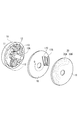
- FIG. 2 is an enlarged exploded perspective view schematically showing a rotation detection switch of the vehicle lever switch device shown in FIG. 1.
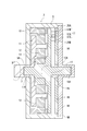
- FIG. 2 is an enlarged longitudinal sectional view schematically showing the inside of a rotation detection switch of the vehicle lever switch device shown in FIG. 1. It is a perspective view which shows the principal part of the conventional vehicle lever switch apparatus.
- FIG. 1 is an external perspective view of a vehicle lever switch device according to an embodiment of the present invention.
- FIG. 2 is an enlarged exploded perspective view schematically showing a rotation detection switch of the vehicle lever switch device shown in FIG.
- FIG. 3 is an enlarged longitudinal sectional view schematically showing the inside of a rotation detection switch of the vehicle lever switch device shown in FIG.
- the vehicle lever switch device 1 detects an operation lever 2 that is swingably supported by a device body 1A that is mounted on a steering column of a vehicle, and a rotation that accompanies a swing operation of the operation lever 2.
- a rotation detection switch 3 is provided.
- the operation lever 2 is rotatably attached to the rotation shaft 5 of the apparatus main body 1A so that the operation lever 2 can be swung in the direction of arrow A or arrow B in FIG.
- the rotation direction of the operation lever 2 is detected by the rotation detection switch 3.
- a fan-shaped drive gear 6 is integrally attached to the rotation shaft 5 of the operation lever 2.
- the drive gear 6 is meshed with a driven gear 8 fitted to a rotation input shaft 7 constituting the rotation detection switch 3.
- the rotational force of the operation lever 2 is transmitted from the drive gear 6 to the driven gear 8.
- the driven gear 8 rotates, the rotation input shaft 7 of the rotation detection switch 3 is rotated, and the rotation of the operation lever 2 is detected.
- the rotation detection switch 3 functions as a sliding rotary encoder that detects the rotation of the operation lever 2 as an on / off change in the current value.
- the rotation detection switch 3 has a bottomed cylindrical case 9 attached to the apparatus main body 1A by fixing means such as screws.
- an annular internal gear 10 that is integrally attached to the case 9, and a disk-shaped planetary gear that is arranged on the inner peripheral portion of the internal gear 10 and rotates in conjunction with the rotation of the rotary input shaft 7.
- Carrier 11, planetary gears 12, 12 rotatably supported on the carrier surface of the planetary gear carrier 11 and meshed with the internal gear 10, and the planetary gears 12, 12 arranged coaxially with the rotary input shaft 7.
- a rotation output shaft 14 integrally formed coaxially with the rotation shaft 13A of the sun gear 13.
- a rotation detector 15 is connected to the rotation output shaft 14.
- the internal gear 10 is fitted and fixed to the inner peripheral portion on the bottom side in the case 9.
- a bearing portion 11 ⁇ / b> A is formed at the rotation center of the planetary gear carrier 11 disposed on the inner peripheral portion of the internal gear 10.
- the rotating shaft 13A of the sun gear 13 is rotatably supported by the bearing portion 11A.
- the rotary input shaft 7 is rotatably supported by a shaft insertion hole 9A formed through the bottom of the case 9, and the tip side protrudes from the bottom of the case 9 to the outside.
- a driven gear 8 is attached to the tip of the rotary input shaft 7 that protrudes outward from the case 9.
- the rotation detection switch 3 having such a configuration, the rotation input to the rotation input shaft 7 can be accelerated and output to the rotation output shaft 14. Accordingly, the rotation angle of the rotation input shaft 7 of the rotation detection switch 3 can be amplified and transmitted to the rotation output shaft 14 to drive the rotation detector 15. Therefore, even when the rotation angle of the operation lever is small, the operation lever Can be detected accurately. Therefore, a highly accurate component configuration is not required.
- a disc-shaped slider carrier 16 constituting a rotation detector 15 is integrally attached to the rotation output shaft 14 of the rotation detection switch 3.
- the slider carrier 16 is rotationally driven by the rotation of the sun gear 13.
- the sun gear 13, the rotary shaft 13A, the rotary output shaft 14 and the slider carrier 16 are integrally formed of a nonconductive resin.
- a slider 17 is mounted on the slider carrier 16 in a state where a pair of slider portions 17B and 17C are electrically connected by a connecting portion 17A.
- Each slider part 17B, 17C is bent in the middle part and is provided with a biasing force.
- the opening 9 ⁇ / b> B of the case 10 is closed by a cover 18 attached integrally with the case 9.
- a disc-shaped circuit board 19 is integrally attached to the lower surface of the cover 18 so as to face the slider placement surface of the slider carrier 16.
- a conductive pattern 20 that is in electrical contact with the slider portions 17B and 17C is formed concentrically on the surface of the circuit board 19 facing the slider carrier.
- the conductive pattern 20 has a first pattern portion 20A formed on the outer diameter side and intermittently arranged with a gap, and a continuous arc-shaped second pattern portion 20B formed on the inner diameter side from the first pattern 20A. ing.
- the first pattern portion 20A is a rotation detection pattern, and is divided into three pieces in the circumferential direction.
- the center pattern is the initial position of the operation lever 2, and the patterns at both ends are in the direction of arrow A in FIG. 1 and a position corresponding to the rotation in the direction of arrow B in FIG.
- the second pattern portion 20B is a ground pattern, the second pattern portion 20B is continuously arranged so as to be always in contact with the slider portion 17C.
- the slider portions 17B and 17C are brought into electrical contact with the pattern portions 20A and 20B, respectively.
- the current flowing between the sliders 17B and 17C is turned off.
- the current between the pattern portions 20A and 20B is conducted through the slider portions 17B and 17C, and the flowing current is turned on, so that the rotary output shaft 14 is rotated to the position of the pattern. Is detected. That is, the rotation direction and rotation angle of the operation lever 2 are detected.
- each slider part 17B, 17C is contacted to each pattern part 20A, 20B by urging
- the first pattern portion 20A serving as the rotation detection pattern is formed on the outer diameter side of the circuit board 19, the first pattern portion 20A serving as the rotation detection pattern can be formed to have a large diameter. Therefore, a change in the rotation angle of the rotation output shaft 14 can be detected as a large change in the circumferential movement dimension of the slider portion 17B, and the rotation detection pattern can be formed with high accuracy with respect to the circumferential dimension. Is not required.
- the first pattern portion 20A may be a ground pattern
- the second pattern portion 20B may be a rotation detection pattern.
- the distal end side of the rotation output shaft 14 is rotatably supported by a bearing portion 18A formed at the center portion of the cover 18.
- the operating lever 2 is swung in the direction of arrow A in FIG.
- the swinging operation of the operating lever 2 is a rotating operation of the rotating shaft 5 of the operating lever 2, and the drive gear 7 attached to the rotating shaft 5 is rotated in the direction of arrow C in FIG.
- the driven gear 8 is rotated in the direction of arrow D in FIG.
- the rotation input shaft 7 is rotated in the direction of arrow D in FIG. 3 by the rotation of the driven gear 8.
- the rotation of the rotation input shaft 7 causes the planetary gear carrier 11 to rotate in the same direction as the rotation input shaft 7 (in the direction of arrow D in FIG. 2). Due to the rotation of the planetary gear carrier 11, the planetary gears 12 and 12 are rotated in the direction of arrow E in FIG. Due to the rotation of the planetary gears 12 and 12, the sun gear 13 is rotated in the direction of arrow F in FIG.
- Rotation of the sun gear 13 causes the rotation output shaft 14 integral with the rotation shaft 13A to rotate, and the slider carrier 16 rotates in the direction of arrow G in FIG.
- the slider portions 17B and 17C slide on the patterns 20A and 20B on the circuit board 19, and the rotation of the rotation output shaft 14 is detected. That is, the rotation of the operation lever 2 is detected.
- the rotation angle of the rotation input shaft 7 of the rotation detection switch 3 is amplified and transmitted to the rotation output shaft 14 to drive the rotation detector 15. Can do. Therefore, even when the rotation angle of the operation lever 2 is small, the rotation of the operation lever 2 can be accurately detected. In addition, a highly accurate component configuration is not required.
- the components for the rotation detection switch 3 can be stored efficiently, and the thickness can be reduced. Therefore, the rotation detection switch 3 can be downsized. .
- the conductive pattern 20 is formed on the inner side of the arc-shaped first pattern portion 20A formed on the circuit board 19 and the first pattern portion 20A.
- Arc-shaped second pattern portion 20B, the first pattern portion 20A is an intermittent detection pattern having a gap in the circumferential direction, and the second pattern portion 20B is a ground pattern continuous in the circumferential direction. Become. Therefore, since the detection pattern can be formed to have a large diameter, the detection pattern is not required to have high accuracy with respect to the circumferential dimension.
- the rotation detection switch 3 is housed in the case 9 that is detachably attached to the device main body 1A. Therefore, since the rotation detection switch 3 can be formed as a single component unit, it is easy to assemble.
- the rotation by the swing operation of the operation lever 2 is transmitted to the rotation input shaft 7 of the rotation detection switch 3 via the drive gear, but the present invention is not limited to this.
- the rotation shaft of the operation lever is attached to the rotation input shaft of the rotation detection switch, and the rotation by the swing operation of the operation lever is directly transmitted to the rotation input shaft of the rotation detection switch. Also good.
- the rotation detection unit 15 detects rotation based on the change in the on / off state of the current value flowing between the slider units 17B and 17C by sliding of the slider units 17B and 17C.
- the present invention is not limited to this.
- the rotation may be detected based on a change in resistance value caused by sliding of the slider portions 17B and 17C.
- a magnet is disposed on the carrier rotated by the sun gear as the rotation detection unit, and a magnetic sensor is disposed on the substrate surface of the circuit board facing the carrier to rotate the operation lever. It is also possible to use a configuration that detects the above with a magnetic sensor.
- the present invention forms a light reflecting surface on a carrier rotated by a sun gear, and provides a light sensor and an LED on the substrate surface of the circuit board facing the carrier, and the emitted light of the LED reflected by the reflecting surface. It is also possible to use a configuration that detects light by an optical sensor.
- the present invention is applied to a vehicle lever switch device that detects rotation of an operation lever due to a swing operation of the operation lever.
- Rotation shaft 14 ⁇ ⁇ ⁇ ⁇ ⁇ Rotation output shaft 15 ⁇ ⁇ ⁇ ⁇ ⁇ Rotation detector 16 ⁇ ⁇ ⁇ ⁇ ⁇ ⁇ ⁇ ⁇ ⁇ ⁇ Slider carrier 17 ⁇ ⁇ ⁇ ⁇ 20 .... Conductive pattern 20A ... 1st pattern part 20B ... 2nd pattern part
Landscapes
- Switches With Compound Operations (AREA)
Abstract
車両用レバースイッチ装置1は、操作レバー2と、操作レバー2の回転を検出する回転検出スイッチ3を有し、回転検出スイッチ3の回転入力軸7の回転速度を歯車機構により増速して回転出力軸14に出力する。そして、回転出力軸14に取り付けられた回転検出部15を駆動させ、操作レバー2の回転を検出する。
Description
本発明は、運転席のステアリング・ホイール等の近くに配置され、操作レバーの回転を検出する車両用レバースイッチ装置に関する。
従来の車両用レバースイッチ装置として、図4に示す構造のものが知られている。図4に示すように、操作レバー100と、操作レバー100の回転を検出する回転検出スイッチ101を備えている。
回転検出スイッチ101の回転入軸102には、操作レバー100の回転軸103に組み付けられた扇形状の駆動歯車104に噛合される従動歯車105が取り付けられている。そして、操作レバー100が揺動されると駆動歯車104が回転し、回転検出スイッチ101の回転入軸102が回転駆動される。この回転入力軸102が回転駆動されると、回転検出スイッチ101のケース106内部に組み込まれている回転検出部が駆動され、操作レバー101の回転が検出される。(特許文献1を参照)
回転検出スイッチ101の回転入軸102には、操作レバー100の回転軸103に組み付けられた扇形状の駆動歯車104に噛合される従動歯車105が取り付けられている。そして、操作レバー100が揺動されると駆動歯車104が回転し、回転検出スイッチ101の回転入軸102が回転駆動される。この回転入力軸102が回転駆動されると、回転検出スイッチ101のケース106内部に組み込まれている回転検出部が駆動され、操作レバー101の回転が検出される。(特許文献1を参照)
ところで、上記の車両用レバースイッチ装置では、操作レバー100の回転角度が小さいものがある。上述のように回転検出スイッチ101の従動歯車105が操作レバー100の駆動歯車104に噛合され、回転検出スイッチ101の回転軸102が回転されると、操作レバー100の小さな回転角度に伴って回転軸102の回転角度も小さくなり、回転検出スイッチ101の回転検出部の回転出力軸の回転角度も小さくなる。
このような構成によれば、操作レバー101の小さな回転角度に合わせ小さな回転角度でも検出できるように回転検出スイッチ101を高精度な部品構成とする必要がある。この構成部品の精度にばらつきが生じたときは、操作レバー101の回転を設計通りに検出ができなくなる恐れがある。
本発明はかかる事情に鑑みてなされたものであり、その目的は、回転検出スイッチの構成部品の精度に頼ることなく、操作レバーの回転を正確に検出できる車両レバースイッチ装置を提供することにある。
本発明に係る車両用レバースイッチ装置は、装置本体に揺動自在に支持された操作レバーと、前記装置本体に取り付けられ前記操作レバーの揺動操作に伴う回転を検出する回転検出スイッチを備えた車両用レバースイッチ装置であって、前記回転検出スイッチは、前記装置本体に固定される円環状の内歯歯車と、前記内歯歯車の内周部に配置され前記操作レバーの回転力が入力される回転入力軸と一体となって回転する遊星歯車キャリアと、前記遊星歯車キャリアのキャリア面上に回転自在に軸支され前記内歯歯車に噛合された遊星歯車と、前記回転入力軸と同軸上に回転自在に配置され前記遊星歯車と噛合された太陽歯車と、前記太陽歯車の回転力が出力される回転出力軸に連結された回転検出部を有することを特徴とする。
この構成によれば、回転検出スイッチの回転入力軸の回転速度を増速して回転出力軸に伝達し、回転検出部を駆動させることができるので、操作レバーの回転角度が小さい場合でも、操作レバーの回転を正確に検出できる。したがって、高精度な部品構成を必要としない。
好適には、本発明は、前記車両用レバースイッチ装置において、前記回転検出部は、前記太陽歯車の回転軸と一体に回転する摺動子キャリアと、前記摺動子キャリア上に取り付けられた摺動子と、前記摺動子キャリアと対向して前記本体に固定され前記摺動子との対向面に前記摺動子と接触する導電パターンが形成された回路基板を有することを特徴とする。
この構成によれば、回転検出スイッチの構成部品の収納効率がよく、回転検出スイッチの小型化を図ることができる。
この構成によれば、回転検出スイッチの構成部品の収納効率がよく、回転検出スイッチの小型化を図ることができる。
好適には、本発明は、前記車両用レバースイッチ装置において、前記導電パターンは、前記回路基板上に形成された円弧状の第1パターン部と、前記第1パターンより内側に形成された円弧状の第2パターン部を有し、前記第1パターン部は円周方向に隙間を有する検出用パターンであり、前記第2パターン部は円周方向に連続したグランド用パターンであることを特徴とする。
この構成によれば、検出用パターンの径を大径に形成できるので、検出用パターンを円周方向の寸法に関して高精度に形成しなくてもよい。
この構成によれば、検出用パターンの径を大径に形成できるので、検出用パターンを円周方向の寸法に関して高精度に形成しなくてもよい。
好適には、本発明は、前記車両用レバースイッチ装置において、前記回転検出スイッチは、前記装置本体に着脱自在に取り付けられるケース内に収納されていることを特徴とする。
この構成によれば、回転検出スイッチを一部品のユニットとして形成することができるので、組み立性がよい。
この構成によれば、回転検出スイッチを一部品のユニットとして形成することができるので、組み立性がよい。
本発明によれば、回転検出スイッチの部品精度に頼ることなく、正確に操作レバーの回転を検出できる車両レバースイッチ装置を提供することができる。
以下、図面を参照しながら、本発明の実施形態に係る車両用レバースイッチ装置について説明する。
図1は、本発明の実施形態に係る車両用レバースイッチ装置の外観斜視図である。図2は、図1に示す車両用レバースイッチ装置の回転検出スイッチを模式的に示す拡大分解斜視図である。図3は、図1に示す車両用レバースイッチ装置の回転検出スイッチの内部を模式的に示す拡大縦断面図である。
図1は、本発明の実施形態に係る車両用レバースイッチ装置の外観斜視図である。図2は、図1に示す車両用レバースイッチ装置の回転検出スイッチを模式的に示す拡大分解斜視図である。図3は、図1に示す車両用レバースイッチ装置の回転検出スイッチの内部を模式的に示す拡大縦断面図である。
(車両用レバースイッチ装置)
本実施形態に係る車両用レバースイッチ装置1は、車両のステアリングコラムに装着される装置本体1Aに揺動自在に支持された操作レバー2と、操作レバー2の揺動操作に伴う回転を検出する回転検出スイッチ3を備えている。
本実施形態に係る車両用レバースイッチ装置1は、車両のステアリングコラムに装着される装置本体1Aに揺動自在に支持された操作レバー2と、操作レバー2の揺動操作に伴う回転を検出する回転検出スイッチ3を備えている。
(回転検出スイッチ)
操作レバー2は、図1中矢印A方向または矢印B方向に揺動自在に操作できるように、基端側が装置本体1Aの回転軸5に回転自在に取り付けられている。操作レバー2を図1中矢印A方向または矢印B方向に回転操作することにより、操作レバー2の回転方向を回転検出スイッチ3により検出する構成となっている。
操作レバー2は、図1中矢印A方向または矢印B方向に揺動自在に操作できるように、基端側が装置本体1Aの回転軸5に回転自在に取り付けられている。操作レバー2を図1中矢印A方向または矢印B方向に回転操作することにより、操作レバー2の回転方向を回転検出スイッチ3により検出する構成となっている。
操作レバー2の回動軸5には扇形状の駆動歯車6が一体的に取り付けられている。駆動歯車6は回転検出スイッチ3を構成する回転入力軸7に嵌合された従動歯車8に噛合されている。操作レバー2の回転力は駆動歯車6から従動歯車8に伝達される。この従動歯車8が回転すると回転検出スイッチ3の回転入力軸7が回転させられ、操作レバー2の回転が検出される。
回転検出スイッチ3は、操作レバー2の回転を電流値のオン・オフの変化として検出する摺動型のロータリーエンコーダとして機能する。
回転検出スイッチ3は、装置本体1Aにネジ止め等の固定手段により、取り付けられる有底筒状のケース9を有している。ケース9内にはケース9と一体に取り付けられた円環状の内歯歯車10と、内歯歯車10の内周部に配置され回転入力軸7の回転に連動して回転する円盤状の遊星歯車キャリア11と、遊星歯車キャリア11のキャリア面上に回転自在に軸支され内歯歯車10に噛合された遊星歯車12、12と、回転入力軸7と同軸上に配置され前記遊星歯車12、12と噛合された太陽歯車13と、太陽歯車13の回転軸13Aと同軸に一体形成された回転出力軸14を有している。回転出力軸14には回転検出部15が連結されている。
回転検出スイッチ3は、装置本体1Aにネジ止め等の固定手段により、取り付けられる有底筒状のケース9を有している。ケース9内にはケース9と一体に取り付けられた円環状の内歯歯車10と、内歯歯車10の内周部に配置され回転入力軸7の回転に連動して回転する円盤状の遊星歯車キャリア11と、遊星歯車キャリア11のキャリア面上に回転自在に軸支され内歯歯車10に噛合された遊星歯車12、12と、回転入力軸7と同軸上に配置され前記遊星歯車12、12と噛合された太陽歯車13と、太陽歯車13の回転軸13Aと同軸に一体形成された回転出力軸14を有している。回転出力軸14には回転検出部15が連結されている。
内歯歯車10は、ケース9内の底部側の内周部に嵌合固定されている。内歯歯車10の内周部に配置された遊星歯車キャリア11の回転中心には軸受部11Aが形成されている。軸受部11Aにより太陽歯車13の回転軸13Aは回転自在に支持されている。
回転入力軸7はケース9の底部に貫通形成された軸挿入穴9Aに回転自在に支持され、先端側はケース9の底部から外部に突出している。ケース9から外部に突出した回転入力軸7の先端には従動歯車8が取り付けられている。
遊星歯車キャリア11のキャリア面上には2個の遊星歯車12、12が遊星歯車キャリア11の直径方向に対向するように配置され、キャリア面上で回転自在に支持されている。遊星歯車12,12は内歯歯車10に噛合されている。
遊星歯車キャリア11を回転入力側とし、太陽歯車13を回転出力側とし、内歯歯車10を固定とすると、回転検出スイッチ3の変速比は、下記式(1)で表される。
[数1]
変速比=(太陽歯車の歯数+内歯歯車の歯数)/太陽歯車の歯数 ・・・(1)
遊星歯車キャリア11を回転入力側とし、太陽歯車13を回転出力側とし、内歯歯車10を固定とすると、回転検出スイッチ3の変速比は、下記式(1)で表される。
[数1]
変速比=(太陽歯車の歯数+内歯歯車の歯数)/太陽歯車の歯数 ・・・(1)
このような構成の回転検出スイッチ3によれば、回転入力軸7に入力される回転を増速して回転出力軸14に出力することができる。
したがって、回転検出スイッチ3の回転入力軸7の回転角度を増幅して回転出力軸14に伝達し、回転検出部15を駆動させることができるので、操作レバーの回転角度が小さい場合でも、操作レバーの回転を正確に検出できる。したがって、高精度な部品構成を必要としない。
したがって、回転検出スイッチ3の回転入力軸7の回転角度を増幅して回転出力軸14に伝達し、回転検出部15を駆動させることができるので、操作レバーの回転角度が小さい場合でも、操作レバーの回転を正確に検出できる。したがって、高精度な部品構成を必要としない。
回転検出スイッチ3の回転出力軸14には回転検出部15を構成する円盤状の摺動子キャリア16が一体に取り付けられている。摺動子キャリア16は太陽歯車13の回転により回転駆動される。なお本実施形態では、太陽歯車13、回転軸13A、回転出力軸14および摺動子キャリア16が非導電性樹脂により一体成型されている。
摺動子キャリア16上には摺動子17が連結部17Aにより電気的に一対の摺動子部17B、17Cを接続した状態で取り付けられている。各摺動子部17B、17Cは中途部分で折り曲げられ、付勢力が備えられている。
ケース10の開口部9Bはケース9と一体に取り付けられたカバー18により蓋閉されている。カバー18の下面には摺動子キャリア16の摺動子配置面と対向するように円盤状の回路基板19が一体に取り付けられている。
回路基板19の摺動子キャリア対向面には摺動子部17B、17Cと電気的に接触された導電パターン20が同心円状に形成されている。
摺動子キャリア16上には摺動子17が連結部17Aにより電気的に一対の摺動子部17B、17Cを接続した状態で取り付けられている。各摺動子部17B、17Cは中途部分で折り曲げられ、付勢力が備えられている。
ケース10の開口部9Bはケース9と一体に取り付けられたカバー18により蓋閉されている。カバー18の下面には摺動子キャリア16の摺動子配置面と対向するように円盤状の回路基板19が一体に取り付けられている。
回路基板19の摺動子キャリア対向面には摺動子部17B、17Cと電気的に接触された導電パターン20が同心円状に形成されている。
導電パターン20は、外径側に形成され隙間をもって間欠的に配置された第1パターン部20Aと、第1パターン20Aより内径側に形成された連続した円弧状の第2パターン部20Bを有している。
第1パターン部20Aは回転検出用パターンとなり、円周方向に3個に分かれて配置されており、中央のパターンが操作レバー2の初期位置で、また両端のパターンがそれぞれ図1中矢印A方向への回転および図1中矢印B方向への回転に対応した位置で摺動子部17Bと接触するように配置されている。また第2パターン部20Bはグランド用パターンとなるため摺動子部17Cと常に接触するように連続して配置されている。
各パターン部20A、20Bには各摺動子部17B、17Cがそれぞれ電気的に接触させられ、第1パターン20Aが無いところでは各摺動子17B、17C間に流れる電流がオフ状態となり、第1パターン20Aがあるところで各パターン部20A、20B間が各摺動子部17B、17Cを介して導通され流れる電流がオン状態となることにより、回転出力軸14がそのパターンの位置に回転したことが検出される。すなわち、操作レバー2の回転方向や回転角度が検出される。なお、各摺動子部17B、17Cは付勢力により各パターン部20A、20Bに接触されており、各摺動子部17B、17Cと各パターン部20A、20Bとの電気的接続状態は安定したものとなる。
第1パターン部20Aは回転検出用パターンとなり、円周方向に3個に分かれて配置されており、中央のパターンが操作レバー2の初期位置で、また両端のパターンがそれぞれ図1中矢印A方向への回転および図1中矢印B方向への回転に対応した位置で摺動子部17Bと接触するように配置されている。また第2パターン部20Bはグランド用パターンとなるため摺動子部17Cと常に接触するように連続して配置されている。
各パターン部20A、20Bには各摺動子部17B、17Cがそれぞれ電気的に接触させられ、第1パターン20Aが無いところでは各摺動子17B、17C間に流れる電流がオフ状態となり、第1パターン20Aがあるところで各パターン部20A、20B間が各摺動子部17B、17Cを介して導通され流れる電流がオン状態となることにより、回転出力軸14がそのパターンの位置に回転したことが検出される。すなわち、操作レバー2の回転方向や回転角度が検出される。なお、各摺動子部17B、17Cは付勢力により各パターン部20A、20Bに接触されており、各摺動子部17B、17Cと各パターン部20A、20Bとの電気的接続状態は安定したものとなる。
この構成によれば、回転検出用パターンとなる第1パターン部20Aを回路基板19の外径側に形成したことにより、回転検出用パターンとなる第1パターン部20Aの径を大径に形成できるので、回転出力軸14の回転角度の変化を摺動子部17Bの大きな円周方向の移動寸法の変化として検出でき、回転検出用パターンの形成に円周方向の寸法に対しての高精度化は要求されない。
なお、本発明は第1パターン部20Aをグランド用パターンとし、第2パターン部20Bを回転検出用パターンとしたものであってもよい。
回転出力軸14の先端側はカバー18の中心部に形成された軸受部18Aによって回転自在に支持されている。
回転出力軸14の先端側はカバー18の中心部に形成された軸受部18Aによって回転自在に支持されている。
(動作)
次に、車両用レバースイッチ装置1の動作について説明する。
操作レバー2を図1中矢印A方向に揺動操作する。この操作レバー2の揺動操作は操作レバー2の回動軸5の回転操作となり、回動軸5に取り付けられている駆動歯車7が図1中矢印C方向に回動される。駆動歯車7の回動により、従動歯車8は、図1中矢印D方向に回動させられる。従動歯車8の回転により回転入力軸7は、図3中矢印D方向に回動させられる。
次に、車両用レバースイッチ装置1の動作について説明する。
操作レバー2を図1中矢印A方向に揺動操作する。この操作レバー2の揺動操作は操作レバー2の回動軸5の回転操作となり、回動軸5に取り付けられている駆動歯車7が図1中矢印C方向に回動される。駆動歯車7の回動により、従動歯車8は、図1中矢印D方向に回動させられる。従動歯車8の回転により回転入力軸7は、図3中矢印D方向に回動させられる。
回転入力軸7の回転により、遊星歯車キャリア11が回転入力軸7と同方向(図2中矢印D方向)に回転させられる。遊星歯車キャリア11の回転により、遊星歯車12、12が図2中矢印E方向に回転させられる。遊星歯車12、12の回転により、太陽歯車13が図2中矢印F方向に回転させられる。
太陽歯車13の回転により、回動軸13Aと一体な回転出力軸14が回転させられ、摺動子キャリア16が図2中矢印G方向に回転させられる。摺動子キャリア16の回転により、摺動子部17B、17Cが回路基板19上の各パターン20A、20B上を摺動し、回転出力軸14の回転を検出する。すなわち、操作レバー2の回転を検出する。
このように本実施形態に係る車両用レバースイッチ装置1によれば、回転検出スイッチ3の回転入力軸7の回転角度を増幅して回転出力軸14に伝達し、回転検出部15を駆動させることができる。
したがって、操作レバー2の回転角度が小さい場合でも、操作レバー2の回転を正確に検出できる。また、高精度な部品構成を必要としない。
したがって、操作レバー2の回転角度が小さい場合でも、操作レバー2の回転を正確に検出できる。また、高精度な部品構成を必要としない。
また、本実施形態に係る車両用レバースイッチ装置1によれば、回転検出スイッチ3の構成部品の収納効率がよく、厚さを薄く形成できるので、回転検出スイッチ3の小型化を図ることができる。
また、本実施形態に係る車両用レバースイッチ装置1によれば、導電パターン20は、回路基板19上に形成された円弧状の第1パターン部20Aと、第1パターン部20Aより内側に形成された円弧状の第2パターン部20Bを有し、第1パターン部20Aは円周方向に隙間を有する間欠状の検出用パターンとなり、第2パターン部20Bは円周方向に連続したグランド用パターンとなる。
したがって、検出用パターンの径を大径に形成できるので、検出用パターンの形成に円周方向の寸法に関して高精度化を要求されない。
したがって、検出用パターンの径を大径に形成できるので、検出用パターンの形成に円周方向の寸法に関して高精度化を要求されない。
また、本実施形態に係る車両用レバースイッチ装置1によれば、回転検出スイッチ3は、装置本体1Aに着脱自在に取り付けられるケース9内に収納されている。
したがって、回転検出スイッチ3を一部品のユニットとして形成することができるので、組み立性がよい。
したがって、回転検出スイッチ3を一部品のユニットとして形成することができるので、組み立性がよい。
以上、本発明の実施形態について説明したが、本発明は上述した実施形態には限定されない。すなわち、当業者は、本発明の技術的範囲またはその均等の範囲内において、上述した実施形態の構成要素に関し、様々な変更、コンビネーション、サブコンビネーション、並びに代替を行ってもよい。
上述した実施形態では、操作レバー2の揺動操作による回転が駆動歯車を介して回転検出スイッチ3の回転入力軸7に伝えられているが、本発明はこれに限定されない。本発明の他の実施形態では、操作レバーの回転軸が回転検出スイッチの回転入力軸に取り付けられ、操作レバーの揺動操作による回転が回転検出スイッチの回転入力軸へ直接伝えられる構成であってもよい。
この構成によれば、駆動歯車や従動歯車を用いる必要はなく、装置の小型化を図ることができる。したがって、運転席のステアリング・ホイール等の近くに配置され、スペースが制限されるステアリングコラムへの設置に好適な車両用レバースイッチ装置を提供することができる。
上述した実施形態では、回転検出部15として、摺動子部17B、17Cの摺動により摺動子部17B、17C間を流れる電流値のオン・オフ状態の変化に基づいて回転を検出する例に挙げているが、本発明はこれに限定されない。例えば摺動子部17B、17Cの摺動による抵抗値の変化に基づいて回転を検出してもよい。さらに本発明の他の実施形態では、回転検出部として、太陽歯車によって回転されるキャリア上に磁石を配置するとともに、キャリアと対向する回路基板の基板面に磁気センサを配置し、操作レバーの回転を磁気センサにより検出する構成のものを使用してもよい。
また、本発明は、太陽歯車によって回転されるキャリア上に光反射面を形成するとともに、キャリアと対向する回路基板の基板面に光センサとLEDを設け、反射面で反射されるLEDの出射光を光センサにより検出する構成のものを使用してもよい。
本発明は、操作レバーの揺動操作による操作レバーの回転を検出する車両用レバースイッチ装置に適用される。
1・・・・・・・・・・・車両用レバースイッチ装置
1A・・・・・・・・・・本体
2・・・・・・・・・・・操作レバー
3・・・・・・・・・・・回転検出スイッチ
7・・・・・・・・・・・回転入力軸
9・・・・・・・・・・・ケース
10・・・・・・・・・・内歯歯車
11・・・・・・・・・・遊星歯車キャリア
12・・・・・・・・・・遊星歯車
13・・・・・・・・・・太陽歯車
13A・・・・・・・・・回転軸
14・・・・・・・・・・回転出力軸
15・・・・・・・・・・回転検出部
16・・・・・・・・・・摺動子キャリア
17・・・・・・・・・・摺動子
17A・・・・・・・・・連結部
17B、17C・・・・・摺動子部
19・・・・・・・・・・回路基板
20・・・・・・・・・・導電パターン
20A・・・・・・・・・第1パターン部
20B・・・・・・・・・第2パターン部
1A・・・・・・・・・・本体
2・・・・・・・・・・・操作レバー
3・・・・・・・・・・・回転検出スイッチ
7・・・・・・・・・・・回転入力軸
9・・・・・・・・・・・ケース
10・・・・・・・・・・内歯歯車
11・・・・・・・・・・遊星歯車キャリア
12・・・・・・・・・・遊星歯車
13・・・・・・・・・・太陽歯車
13A・・・・・・・・・回転軸
14・・・・・・・・・・回転出力軸
15・・・・・・・・・・回転検出部
16・・・・・・・・・・摺動子キャリア
17・・・・・・・・・・摺動子
17A・・・・・・・・・連結部
17B、17C・・・・・摺動子部
19・・・・・・・・・・回路基板
20・・・・・・・・・・導電パターン
20A・・・・・・・・・第1パターン部
20B・・・・・・・・・第2パターン部
Claims (4)
- 装置本体に揺動自在に支持された操作レバーと、
前記装置本体に取り付けられ前記操作レバーの揺動操作に伴う回転を検出する回転検出スイッチと、
を備えた車両用レバースイッチ装置であって、
前記回転検出スイッチは、
前記装置本体に固定される円環状の内歯歯車と、
前記内歯歯車の内周部に配置され前記操作レバーの回転力が入力される回転入力軸と一体となって回転する遊星歯車キャリアと、
前記遊星歯車キャリアのキャリア面上に回転自在に軸支され前記内歯歯車に噛合された遊星歯車と、
前記回転入力軸と同軸上に回転自在に配置され前記遊星歯車と噛合された太陽歯車と、
前記太陽歯車の回転力が出力される回転出力軸に連結された回転検出部と、
を有する車両用レバースイッチ装置。 - 前記回転検出部は、
前記太陽歯車の回転軸と一体に回転する摺動子キャリアと、
前記摺動子キャリア上に取り付けられた摺動子と、
前記摺動子キャリアと対向して前記本体に固定され前記摺動子との対向面に前記摺動子と接触する導電パターンが形成された回路基板と、
を有する請求項1に記載の車両用レバースイッチ装置。 - 前記導電パターンは、前記回路基板上に形成された円弧状の第1パターン部と、前記第1パターンより内側に形成された円弧状の第2パターン部を有し、
前記第1パターン部は円周方向に隙間を有する検出用パターンであり、前記第2パターン部は円周方向に連続したグランド用パターンであることを特徴とする請求項2に記載の車両用レバースイッチ装置。 - 前記回転検出スイッチは、前記装置本体に着脱自在に取り付けられるケース内に収納されている請求項1~3のいずれかに記載の車両用レバースイッチ装置。
Applications Claiming Priority (2)
| Application Number | Priority Date | Filing Date | Title |
|---|---|---|---|
| JP2016052756 | 2016-03-16 | ||
| JP2016-052756 | 2016-03-16 |
Publications (1)
| Publication Number | Publication Date |
|---|---|
| WO2017159202A1 true WO2017159202A1 (ja) | 2017-09-21 |
Family
ID=59852297
Family Applications (1)
| Application Number | Title | Priority Date | Filing Date |
|---|---|---|---|
| PCT/JP2017/005768 Ceased WO2017159202A1 (ja) | 2016-03-16 | 2017-02-16 | 車両用レバースイッチ装置 |
Country Status (1)
| Country | Link |
|---|---|
| WO (1) | WO2017159202A1 (ja) |
Citations (3)
| Publication number | Priority date | Publication date | Assignee | Title |
|---|---|---|---|---|
| JP2002343170A (ja) * | 2001-05-15 | 2002-11-29 | Omron Corp | セーフティスイッチ装置 |
| JP2003084848A (ja) * | 2001-09-10 | 2003-03-19 | Alps Electric Co Ltd | 手動入力装置 |
| JP2006147402A (ja) * | 2004-11-22 | 2006-06-08 | Alps Electric Co Ltd | 回転操作型電気部品 |
-
2017
- 2017-02-16 WO PCT/JP2017/005768 patent/WO2017159202A1/ja not_active Ceased
Patent Citations (3)
| Publication number | Priority date | Publication date | Assignee | Title |
|---|---|---|---|---|
| JP2002343170A (ja) * | 2001-05-15 | 2002-11-29 | Omron Corp | セーフティスイッチ装置 |
| JP2003084848A (ja) * | 2001-09-10 | 2003-03-19 | Alps Electric Co Ltd | 手動入力装置 |
| JP2006147402A (ja) * | 2004-11-22 | 2006-06-08 | Alps Electric Co Ltd | 回転操作型電気部品 |
Similar Documents
| Publication | Publication Date | Title |
|---|---|---|
| JP4203371B2 (ja) | 回転検出装置及びこれを備えた自動車 | |
| US8573086B2 (en) | Lever operation device | |
| US9097559B2 (en) | Non-contact multi-turn absolute position magnetic sensor comprising a through-shaft | |
| JP4927112B2 (ja) | 駆動装置 | |
| JP4066037B2 (ja) | 操作パネルの回転スイッチ機構 | |
| JP2008007075A (ja) | 舵角センサ組み込み式回転コネクタ装置 | |
| FR2947902A1 (fr) | Capteur de position absolue et multi-periodique | |
| JP5097364B2 (ja) | 舵角センサ組み込み式回転コネクタ装置 | |
| JP2006017663A (ja) | 回転角検出装置 | |
| JP2009224057A (ja) | ストークスイッチ装置 | |
| JP5197366B2 (ja) | 回転インデキシング装置、および回転インデキシング装置を備える制御装置 | |
| JP2010112414A (ja) | ギヤボックスの駆動機構 | |
| WO2017159202A1 (ja) | 車両用レバースイッチ装置 | |
| JP2009063393A (ja) | 回転角度検出装置 | |
| JP2005091092A (ja) | 位置検出センサ | |
| JP2003307419A (ja) | 舵角検出装置 | |
| JP2015220065A (ja) | 電子機器 | |
| JP2011192392A (ja) | レバー操作装置 | |
| JP2023155639A (ja) | 回転検出装置 | |
| JP2015216039A (ja) | 操作レバー装置 | |
| JP2011022074A (ja) | 多回転角度検出装置 | |
| WO2018173571A1 (ja) | パワーステアリング装置 | |
| JP2020157929A (ja) | シフト装置 | |
| JP4733591B2 (ja) | シフト装置 | |
| JP2005180959A (ja) | 回転検出装置 |
Legal Events
| Date | Code | Title | Description |
|---|---|---|---|
| NENP | Non-entry into the national phase |
Ref country code: DE |
|
| 121 | Ep: the epo has been informed by wipo that ep was designated in this application |
Ref document number: 17766209 Country of ref document: EP Kind code of ref document: A1 |
|
| 122 | Ep: pct application non-entry in european phase |
Ref document number: 17766209 Country of ref document: EP Kind code of ref document: A1 |
|
| NENP | Non-entry into the national phase |
Ref country code: JP |