WO2017154794A1 - 動力伝達装置 - Google Patents
動力伝達装置 Download PDFInfo
- Publication number
- WO2017154794A1 WO2017154794A1 PCT/JP2017/008594 JP2017008594W WO2017154794A1 WO 2017154794 A1 WO2017154794 A1 WO 2017154794A1 JP 2017008594 W JP2017008594 W JP 2017008594W WO 2017154794 A1 WO2017154794 A1 WO 2017154794A1
- Authority
- WO
- WIPO (PCT)
- Prior art keywords
- pulley
- hub
- ball
- cylindrical portion
- diameter
- Prior art date
Links
Images


Classifications
-
- F—MECHANICAL ENGINEERING; LIGHTING; HEATING; WEAPONS; BLASTING
- F16—ENGINEERING ELEMENTS AND UNITS; GENERAL MEASURES FOR PRODUCING AND MAINTAINING EFFECTIVE FUNCTIONING OF MACHINES OR INSTALLATIONS; THERMAL INSULATION IN GENERAL
- F16D—COUPLINGS FOR TRANSMITTING ROTATION; CLUTCHES; BRAKES
- F16D7/00—Slip couplings, e.g. slipping on overload, for absorbing shock
- F16D7/04—Slip couplings, e.g. slipping on overload, for absorbing shock of the ratchet type
- F16D7/06—Slip couplings, e.g. slipping on overload, for absorbing shock of the ratchet type with intermediate balls or rollers
- F16D7/10—Slip couplings, e.g. slipping on overload, for absorbing shock of the ratchet type with intermediate balls or rollers moving radially between engagement and disengagement
-
- F—MECHANICAL ENGINEERING; LIGHTING; HEATING; WEAPONS; BLASTING
- F16—ENGINEERING ELEMENTS AND UNITS; GENERAL MEASURES FOR PRODUCING AND MAINTAINING EFFECTIVE FUNCTIONING OF MACHINES OR INSTALLATIONS; THERMAL INSULATION IN GENERAL
- F16D—COUPLINGS FOR TRANSMITTING ROTATION; CLUTCHES; BRAKES
- F16D43/00—Automatic clutches
- F16D43/02—Automatic clutches actuated entirely mechanically
- F16D43/20—Automatic clutches actuated entirely mechanically controlled by torque, e.g. overload-release clutches, slip-clutches with means by which torque varies the clutching pressure
- F16D43/202—Automatic clutches actuated entirely mechanically controlled by torque, e.g. overload-release clutches, slip-clutches with means by which torque varies the clutching pressure of the ratchet type
- F16D43/204—Automatic clutches actuated entirely mechanically controlled by torque, e.g. overload-release clutches, slip-clutches with means by which torque varies the clutching pressure of the ratchet type with intermediate balls or rollers
- F16D43/208—Automatic clutches actuated entirely mechanically controlled by torque, e.g. overload-release clutches, slip-clutches with means by which torque varies the clutching pressure of the ratchet type with intermediate balls or rollers moving radially between engagement and disengagement
-
- F—MECHANICAL ENGINEERING; LIGHTING; HEATING; WEAPONS; BLASTING
- F16—ENGINEERING ELEMENTS AND UNITS; GENERAL MEASURES FOR PRODUCING AND MAINTAINING EFFECTIVE FUNCTIONING OF MACHINES OR INSTALLATIONS; THERMAL INSULATION IN GENERAL
- F16H—GEARING
- F16H55/00—Elements with teeth or friction surfaces for conveying motion; Worms, pulleys or sheaves for gearing mechanisms
- F16H55/32—Friction members
- F16H55/36—Pulleys
Definitions
- the present invention relates to a power transmission device that transmits power from an engine to an automobile auxiliary machine.
- Patent Document 1 proposes a power transmission device having a torque limiter mechanism.
- a pulley for transmitting engine power via a belt a hub attached to a rotating shaft of a compressor, and a torque limiter mechanism provided between the hub and the pulley. And have.
- the torque limiter mechanism connects one end of an arc-shaped connecting member to a pulley, and the other end of the connecting member is provided with a slit having a wide portion that opens at the end of the connecting member.
- a columnar body formed by a rivet that penetrates the flange of the hub and a collar through which the rivet penetrates is provided, the columnar body is inserted into the wide portion of the slit, and a disc spring is incorporated between the hub and the connecting member.
- An object of the present invention is to provide a power transmission device that generates less noise during operation of a torque limiter mechanism.
- a pulley supported rotatably around a pulley support shaft provided coaxially with a rotation shaft of an automobile accessory, and the pulley and the rotation shaft
- a torque limiter mechanism which is provided between the pulley and transmits the rotation of the pulley to the rotating shaft and cuts off the rotation transmission from the pulley to the rotating shaft when the rotational load of the rotating shaft exceeds a set value.
- the torque limiter mechanism is attached to an annular cover connected to the outer surface of the pulley, a plurality of balls held on the inner periphery of the cover, and a shaft end of the rotating shaft.
- a plurality of pocket tube portions that elastically hold the ball in a state in which a part of the ball is exposed to the inner diameter side in the cylindrical portion. Set at intervals.
- a V groove into which a part of the ball is fitted is provided on the outer diameter surface of the hub, and the pushing force to the ball is directed radially outward from the inside of the pocket cylindrical portion between the adjacent V grooves of the hub. It is set as the structure provided with the press part which loads.
- the cover rotates together with the pulley, and the rotation is transmitted to the hub from the ball held by the cover and the engaging portion of the V groove formed on the outer periphery of the hub.
- the rotating shaft rotates and the automobile auxiliary machine operates.
- the ball When there is a change in the load of an automobile accessory or a change in rotational torque applied to the pulley from the engine, the ball is displaced in the pocket cylinder by the pressing force applied to the ball from the inclined inner surface of the V groove, and the movement As a result, the pocket tube portion is elastically deformed to absorb the torque fluctuation.
- a plurality of slits extending in the axial direction are formed in the pocket cylindrical portion at intervals in the circumferential direction, and the pocket cylindrical portion is elastically deformed by elastically holding the ball with an elastic piece formed between adjacent slits. This makes it easy to obtain a good damper effect.
- the cover formed with the pocket cylindrical portion for holding the ball includes an annular plate portion connected to the outer surface of the pulley, a large-diameter cylindrical portion facing outward from the inner periphery of the annular plate portion, and the large-diameter cylindrical portion.
- the pulley has an inner flange portion facing the inner diameter surface of the boss portion formed on the pulley with a gap, and the pocket cylindrical portion is formed on the small diameter cylindrical portion.
- annular space is formed by the large diameter cylindrical portion, the outer flange portion, the small diameter cylindrical portion, and the inner flange portion, and the ball pushed out from the pocket cylindrical portion is held in the annular space. It will be. As a result, it is possible to prevent the peripheral device from being damaged or causing troubles due to the falling of the ball to the outside.
- each of the inner peripheral portion and the inner flange portion of the outer flange portion connected to both ends in the axial direction of the small-diameter cylindrical portion and the small-diameter cylindrical portion is divided between adjacent pocket cylindrical portions in the circumferential direction. If the slits are formed, elasticity can be imparted to the divided pieces between the adjacent slits, so that the ball can move smoothly with respect to the inner surface of the V-groove.
- the hub material should be sintered or resin.
- the hub can be easily formed by molding, and a low-cost hub can be obtained.
- the ball moves in the pocket cylinder part and the automobile auxiliary element is elastically deformed by the pocket cylinder part due to the deviation movement. It is possible to absorb the load fluctuation of the machine and the torque fluctuation from the engine, and to smoothly drive the automobile auxiliary machine.
- FIG. 9 is a right side view of the pulley with limiter shown in Fig. 9.
- Sectional view along line XI-XI in Fig. 9 Sectional view along line XII-XII in FIG.
- Sectional view along line XIV-XIV in Fig. 14A The figure which shows the state which the ball
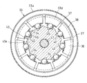
- the power transmission device includes a pulley 10 to which power from an engine (not shown) is transmitted, a rotating shaft 21 of an automobile auxiliary machine 20, and a mutual connection between the pulley 10 and the rotating shaft 21.
- the torque limiter mechanism 30 is provided between the pulley 10 and the rotation of the pulley 10 so as to transmit the rotation to the rotation shaft 21 and cut off the rotation transmission from the pulley 10 to the rotation shaft 21 when the rotation load of the rotation shaft 21 increases.
- the pulley 10 has a belt guide wheel 11, an annular plate 12 provided on the inner periphery of the belt guide wheel 11, and a cylindrical boss portion 13 provided on the inner periphery of the annular plate 12.
- a pair of flanges 14 are provided on both sides of the outer periphery of the guide wheel 11, and a plurality of V-shaped grooves 15 around which the V belt is wound are provided between the pair of flanges 14.
- a bearing housing 16 is incorporated inside the boss 13.
- the bearing housing 16 is secured by an annular projecting portion 13 a provided on the inner periphery of one end of the boss portion 13.
- the bearing housing 16 is prevented from rotating by a serration 17 formed on the outer periphery of one end and the inner periphery of one end of the boss portion 13, and a rolling bearing 18 is incorporated in the bearing housing 16.
- a double row ball bearing is employed as the rolling bearing 18.
- the rolling bearing 18 is press-fitted into a cylindrical pulley support shaft 23 provided in the housing 22 of the automobile auxiliary machine 20 and is prevented from being removed by a retaining ring 24 attached to the outer periphery of the end of the pulley support shaft 23.
- a compressor for an air conditioner is employed as the automobile auxiliary machine 20.
- the pulley support shaft 23 provided on the housing 22 of the automobile auxiliary machine 20 is provided coaxially with the rotary shaft 21, and the pulley 10 is supported rotatably about the pulley support shaft 23.
- the torque limiter mechanism 30 includes an annular cover 31 provided on the outer surface of the pulley 10, a plurality of balls 42 held on the inner periphery of the cover 31, and a hub 43 attached to the shaft end of the rotating shaft 21. It consists of.
- the cover 31 is made of a press-formed product of a metal plate provided with an annular cylindrical portion 33 on the inner periphery of the annular plate portion 32.
- the annular cylindrical portion 33 has a bowl-shaped cross section, and has a large-diameter cylindrical portion 33a facing outward from the inner periphery of the annular plate portion 32, and an outer flange portion 33b facing radially inward from the end of the large-diameter cylindrical portion 33a.
- the small-diameter cylindrical portion 33c which is a cylindrical portion facing inward from the inner peripheral portion of the outer flange portion 33b, and the inner flange portion 33d facing in the outer-diameter direction from the end portion of the small-diameter cylindrical portion 33c.
- the small-diameter cylindrical portion 33c is formed with a plurality of pocket cylindrical portions 34 protruding inward at equal intervals in the circumferential direction, and balls 42 are incorporated in the pocket cylindrical portions 34. Yes.
- the ball 42 is incorporated so that a part of the outer periphery is exposed from both ends of the pocket cylindrical portion 34.
- a plurality of axial slits 35 are provided in the pocket cylinder portion 34 at intervals in the circumferential direction, and the balls 42 are elastically held by elastic pieces 36 formed between the adjacent slits 35.
- the annular cylindrical portion 33 is formed with a slit 37 between adjacent pocket cylindrical portions 34, and the slit 37 forms a small diameter cylindrical portion 33 c and an outer flange portion connected to both axial ends of the small diameter cylindrical portion 33 c.
- Each of the inner peripheral portion 33d and the inner flange portion 33d is divided in the circumferential direction, and a U-shaped divided piece portion 38 that can be elastically deformed is provided on the inner flange portion 33d side.
- the cover 31 is attached so that the annular plate portion 32 abuts the outer surface of the annular plate 12 in the pulley 10.
- a nut fitting hole 39 is provided in the annular plate 12 of the pulley 10
- a nut 40 is fitted in the nut fitting hole 39, and a screw 41 screwed into the nut 40 is tightened to cover the cover 31.
- 31 is attached, but a screw hole may be directly formed in the annular plate 12 of the pulley 10, and the screw 41 may be screwed into the screw hole.
- the hub 43 has a configuration in which a small-diameter shaft portion 43b is provided on one side surface of the disc portion 43a, and a shaft hole 44 that opens at an end surface of the small-diameter shaft portion 43b is formed.
- the hub 43 is set on the small-diameter shaft portion 21 a so that the small-diameter shaft portion 21 a formed at the shaft end portion of the rotary shaft 21 is fitted in the shaft hole 44, and is formed on the shaft center of the hub 43.
- the bolt 47 is screwed into the screw hole 46 provided in the small-diameter shaft portion 21a from the inserted insertion hole 45 and attached to the rotary shaft 21. At this time, the shaft hole 44 and the small-diameter shaft portion 21a are fitted by a serration 48, and the hub 43 is prevented from rotating around the rotary shaft 21.
- the disc portion 43a is accommodated in the small diameter side cylindrical portion 33c of the cover 31, and a plurality of V grooves 49 are formed at equal pitches on the outer diameter surface of the disc portion 43a.
- the V-grooves 49 have different inclination angles of the inner side surfaces 49a and 49b facing each other in the circumferential direction.
- the inner side surfaces 49a and 49b have the same inclination angle. It may be.
- the disc portion 43a of the hub 43 is provided with a pressing portion 50 that can push the ball 42 radially outward from the pocket cylindrical portion 34 between adjacent V grooves. It has been.
- the pressing portion 50 is composed of an arcuate protrusion, but the outer diameter surface of the disk portion 43a between the adjacent V grooves 49 may be used as the pressing portion 50.
- the hub 43 is a molded product made of a sintered material in order to reduce component costs, but may be a molded product made of resin.
- the power transmission device shown in the embodiment has the above-described structure.
- the pulley 10 rotates in the forward direction indicated by the arrow in FIG. Is transmitted to the hub 43 from the engaging portion between the ball 42 and the inner surface 49a of the V-groove 49 shown in FIGS. 5A and 5B, the rotating shaft 21 shown in FIG. 1 rotates, and the automobile auxiliary machine 20 operates.
- the ball 42 that has slipped out of the pocket cylindrical portion 34 is accommodated in the annular cylindrical portion 33 shown in FIG. For this reason, there is no inconvenience that the peripheral device is damaged or trouble occurs due to the drop of the ball 42 to the outside.
- This pulley with a limiter includes a pulley 51, a hub 52 disposed at the center of the pulley 51, and a torque limiter 53 that transmits rotational torque from the pulley 51 to the hub 52.
- a drive belt 54 is wound around the outer periphery of the pulley 51.
- the drive belt 54 is connected to a crankshaft of an engine (not shown). When the engine operates and the crankshaft rotates, the rotation of the crankshaft is transmitted to the pulley 51 via the drive belt 54. .
- the pulley 51 includes a cylindrical rim portion 56 having a circumferential groove 55 that engages with the drive belt 54 on the outer periphery, a cylindrical boss portion 57 disposed inside the rim portion 56, a rim portion 56, and a boss portion 57. And a connecting portion 58 for connecting the two.
- the rim portion 56, the boss portion 57, and the connecting portion 58 are integrally formed of resin.
- a rolling bearing 59 that rotatably supports the pulley 51 is attached to the inner periphery of the boss portion 57. Inside the rolling bearing 59, a cylindrical support shaft 61 is provided that is fixed to an automobile accessory 60 (for example, a compressor for a car air conditioner).
- a metal nut 62 for fixing the torque limiter 53 is embedded in the connecting portion 58.
- the hub 52 is fixed to the shaft end portion of the driven shaft 63 located at the rotation center of the pulley 51 with a bolt 64.
- the driven shaft 63 is a shaft that is rotationally driven by a drive belt 54 wound around the outer periphery of the pulley 51, and the automobile auxiliary device 60 is driven using the rotational force of the driven shaft 63 as power.
- the hub 52 includes a spline cylinder portion 65 that fits a spline formed on the outer periphery of the shaft end portion of the driven shaft 63, and a flange portion 66 that is integrally formed on the outer periphery of the spline cylinder portion 65.
- the torque limiter 53 is formed on the outer periphery of the first annular plate 71, the second annular plate 72 provided to face the first annular plate 71 in the axial direction, and the flange portion 66 of the hub 52. And a ball 74 accommodated in the V-groove 73.
- Each of the first annular plate 71 and the second annular plate 72 is formed of a metal plate, and is fixed to the side surface of the pulley 51 with a bolt 75.
- a plurality of V grooves 73 are provided at intervals in the circumferential direction, and a plurality of balls 74 are also provided correspondingly.
- the first annular plate 71 has a flat plate shape that is orthogonal to the axial direction as a whole.
- the second annular plate 72 is spaced apart from the outer flat plate portion 76 fixed to the outer diameter side portion of the first annular plate 71 and the inner diameter side portion of the first annular plate 71 in the axial direction.
- the inner flat plate portion 77 arranged in parallel, the outer cylindrical portion 78 connecting the radial inner end of the outer flat plate portion 76 and the radial outer end of the inner flat plate portion 77, and the radial inner end of the inner flat plate portion 77.
- an inner cylindrical portion 79 extending in the axial direction toward the first annular plate 71 (see FIG. 13).
- the V-groove 73 is a groove having a V-shaped cross-section perpendicular to the axial direction, and is formed such that the radial depth gradually decreases from the center in the circumferential direction toward both sides in the circumferential direction. ing.
- a groove in which a cross-sectional shape orthogonal to the axial direction forms two straight lines that intersect at an angle in the range of 30 ° to 50 ° can be employed.
- the ball 74 has an outer diameter such that it protrudes from the V groove 73 to the outer diameter side in a state of being accommodated in the deepest position of the V groove 73.
- the ball 74 is made of steel.
- the second annular plate 72 has a plurality of pairs of slits 80 corresponding to the number of balls 74.
- Each pair of slits 80 is composed of two slits positioned at intervals in the circumferential direction.
- each pair of slits 80 crosses the inner cylindrical portion 79 in the axial direction, and further extends radially outward from the boundary between the inner cylindrical portion 79 and the inner flat plate portion 77 in the inner flat plate portion 77. It is formed as follows.
- a spring piece 81 extending in the axial direction is formed in a portion between adjacent slits 80 of the inner cylindrical portion 79.
- the spring piece 81 is a portion that bends radially outward when the ball 74 (see FIG. 11) moves radially outward and applies a radially inward biasing force to the ball 74.
- the width of each slit 80 is set to be smaller than the outer diameter of the ball 74.
- the spring piece 81 has a hole portion 82 that fits into the ball 74 and a separation portion 83 that divides the circumference of the hole portion 82.
- the hole portion 82 has a circular edge having a smaller diameter than the outer diameter of the ball 74.
- the separation part 83 is a cut that extends in the axial direction from the inner periphery of the hole part 82 and opens to the tip of the spring piece 81.
- the first annular plate 71 has a stopper portion 84 (in the drawing, the radial direction of the first annular plate 71 in the figure) that is positioned with a gap radially outward of the spring piece 81. A peripheral edge of the inner end). The size of the gap between the spring piece 81 and the stopper portion 84 is narrower than the outer diameter of the ball 74.
- the stopper portion 84 is a portion that receives the spring piece 81 and regulates the amount of deflection of the spring piece 81 when the spring piece 81 bends radially outward.
- a ball housing portion 85 is formed in a space surrounded by the outer cylindrical portion 78, the inner flat plate portion 77, and the inner cylindrical portion 79 of the plate 72.
- the ball accommodating portion 85 is a space that receives the ball 74 when the ball 74 passes the spring piece 81 and moves radially outward.
- the ball 74 deflects the spring piece 81 radially outward in accordance with the rotational torque acting between the pulley 51 (see FIG. 9) and the hub 52.
- the pulley 51 (see FIG. 9) and the hub 52 are relatively displaced in the circumferential direction by moving radially outward along the V-groove 73. Therefore, the fluctuation of the rotational load of the driven shaft 63 shown in FIG. 9 and the fluctuation of the rotational torque transmitted from the driving belt 54 to the pulley 51 can be absorbed between the pulley 51 and the hub 52 to obtain a damper action. Can do.
- the balls 74 are formed in the holes of the spring pieces 81 as shown in FIGS. 16A and 16B. 82 and the separation part 83 are pushed and spread outward in the radial direction, and the ball 74 is received in the ball accommodating part 85. In this state, since there is no ball 74 in the V-groove 73, transmission of rotational torque between the pulley 51 (see FIG. 9) and the hub 52 is interrupted. As described above, when the rotational load of the driven shaft 63 becomes excessive, the torque limiter 53 shown in FIG. 9 idles the pulley 51 by interrupting the transmission of the rotational torque from the pulley 51 to the hub 52. By protecting the drive belt 54, the vehicle can travel to the repair shop.
- This pulley with a limiter cuts off the transmission of rotational torque between the pulley 51 and the hub 52 when the automobile accessory 60 is damaged and the rotational load of the driven shaft 63 becomes excessive, and the drive belt 54 is Protect. Further, even if the pulley 51 rotates in this state, there is no portion that repeatedly collides with the rotation of the pulley 51, so that abnormal noise is unlikely to occur.
- this pulley with a limiter has a stopper portion 84 that receives the spring piece 81 and regulates the amount of deflection of the spring piece 81 when the spring piece 81 bends radially outward. It is possible to set the rotational torque at which the torque limiter 53 operates to be relatively large while ensuring a damper action by moving along.
- the slit 80 is formed so as to extend radially outward from the boundary between the inner cylindrical portion 79 and the inner flat plate portion 77, the spring piece 81 is elastically deformed. This makes it possible to obtain a damper action effectively.
- each slit 80 is set to be smaller than the outer diameter of the ball 74, when the ball receiving portion 85 receives the ball 74, the ball 74 is slit. It is possible to prevent dropping through 80.
- a torque limiter that shuts off In a pulley with a limiter having The torque limiter is A V-groove provided on the outer periphery of the hub such that the radial depth gradually decreases from the circumferential center toward both sides in the circumferential direction; A ball housed in the V-groove; A hole that fits into the ball and a cut-out portion that divides the circumference of the hole, and the ball deflects radially outward when the ball moves radially outward; A spring piece for applying an inward biasing force; A ball housing portion that receives the ball when the ball has passed through the hole portion and the cut-out portion and radially outward; A pulley with a limiter.
- the torque limiter is Additional notes further comprising a stopper portion that is positioned with a gap radially outward of the spring piece, and that receives the spring piece and regulates the amount of deflection of the spring piece when the spring piece is deflected radially outward.
- the pulley with a limiter according to 1.
- the torque limiter is A first annular plate fixed to a side surface of the pulley; A second annular plate provided in the first annular plate so as to face the axial direction; The spring piece is provided to extend in the axial direction at the radially inner end of the second annular plate, The stopper portion is provided at a radially inner end of the first annular plate,
- the pulley with limiter according to appendix 2 wherein the ball housing portion is a space formed between opposing surfaces of the first annular plate and the second annular plate.
- the second annular plate includes an inner flat plate portion arranged in parallel with the first annular plate at an axial interval, and a first annular plate from a radially inner end of the inner flat plate portion. And an inner cylindrical portion that extends in the axial direction toward the surface, and at least a pair of slits that are formed across the inner cylindrical portion in the axial direction, and the spring piece is formed between the pair of slits. 3.
Abstract
プーリ(10)と自動車補機(20)の回転軸(21)との間に設けられたトルクリミッタ機構(30)を、プーリ(10)の外側面に連結された環状のカバー(31)と、カバー(31)の内周に保持された複数のボール(42)と、回転軸の軸端部に取り付けられたハブ(43)とで形成する。カバー(31)にハブ(43)を覆う円筒部(33c)を設け、円筒部(33c)にボール(42)を弾性保持するポケット筒部(34)を設け、ハブ(43)の外径面にV溝(49)を設け、そのV溝(49)にボール(42)を係合し、その係合部によりプーリ(10)の回転を回転軸(21)に伝達する。自動車補機(20)が故障して回転軸(21)の回転負荷が大きくなった際には、V溝(49)の内側面からボール(42)に押圧力を負荷し、そのV溝(49)の内側面に沿ってボール(42)を移動させてV溝(49)に対するボール(42)の係合を解除し、プーリ(10)から回転軸(21)への回転伝達を遮断する。
Description
この発明は、エンジンからの動力を自動車補機に伝達する動力伝達装置に関する。
一般に、エアコンディショナ用コンプレッサ等の自動車補機の駆動に際しては、エンジンのクランクシャフトの回転をベルト伝動装置によって自動車補機の回転軸に伝達している。このとき、自動車補機の回転軸の回転負荷が大きくなると、ベルトの張力が大きくなって回転軸に取り付けられたプーリとベルトの接触部で滑りが生じ、ベルトが損傷する可能性がある。
そのような不都合を解消するため、下記特許文献1においては、トルクリミッタ機構を有する動力伝達装置を提案している。同文献1に記載された動力伝達装置においては、エンジンの動力がベルトを介して伝達されるプーリと、コンプレッサの回転軸に取り付けられたハブと、そのハブとプーリ間に設けられたトルクリミッタ機構とを有している。
トルクリミッタ機構は、プーリに円弧状の連結部材の一端部を連結し、その連結部材の他端部に、連結部材の端縁で開口する幅広部を有するスリットを設け、一方、ハブには、そのハブのフランジを貫通するリベットと、そのリベットが貫通するカラーとによって形成される柱状体を設け、その柱状体を上記スリットの広幅部に挿入し、上記ハブと連結部材間に皿ばねを組み込んで、連結部材の他端部とリベットの頭部を弾性接触し、その弾性接触部において、プーリの回転をハブに伝えるようにしている。また、回転軸の回転負荷が大きくなると、弾性接触部で滑りを生じさせ、スリットからの柱状体の抜け出しによりトルク伝達を遮断して、プーリをフリー回転させるようにしている。
ところで、上記特許文献1に記載された動力伝達装置においては、連結部材がプーリとハブとを連結する状態で変形状態にあるため、長期間にわたって連結状態に保持されていると塑性変形し、柱状体がスリットの広幅部から抜け出すトルクリミッタ機構の動作状態で、プーリと共に回転する連結部材がリベットの頭部と干渉して異音を発生し続け、不快感を与える可能性がある。
この発明の課題は、トルクリミッタ機構の動作時に異音を発生させることが少ない動力伝達装置を提供することである。
上記の課題を解決するため、この発明においては、自動車補機の回転軸と同軸上に設けられたプーリ支持軸を中心にして回転自在に支持されたプーリと、そのプーリと前記回転軸との間に設けられてプーリの回転を前記回転軸に伝達し、その回転軸の回転負荷が設定値を超えた際にプーリから回転軸への回転伝達を遮断するトルクリミッタ機構とを有してなる動力伝達装置において、前記トルクリミッタ機構が、前記プーリの外側面に連結された環状のカバーと、そのカバーの内周に保持された複数のボールと、前記回転軸の軸端部に取り付けられたハブとを備え、前記カバーが前記ハブを覆う円筒部を内周に有し、その円筒部にボールの一部が内径側に露出する状態でボールを弾性保持する複数のポケット筒部が周方向に間隔をおいて設けられ、前記ハブの外径面には前記ボールの一部が嵌合するV溝を設けられ、前記ハブの隣接するV溝間にはポケット筒部内から径方向外方に向けてボールに押出し力を負荷する押圧部が設けられた構成としている。
上記の構成からなる動力伝達装置において、プーリが回転すると、そのプーリと共にカバーが回転し、その回転がカバーに保持されたボールとハブの外周に形成されたV溝の係合部からハブに伝達されて回転軸が回転し、自動車補機が作動する。
自動車補機の負荷変動やエンジンからプーリに負荷される回転トルクの変動が生じると、V溝の傾斜状の内側面からボールに負荷される押圧力によりボールがポケット筒部内でずれ動き、その移動によりポケット筒部が弾性変形してトルクの変動を吸収する。
ここで、ポケット筒部に軸方向に延びる複数のスリットを周方向に間隔をおいて形成し、隣接するスリット間に形成された弾性片でボールを弾性保持することにより、ポケット筒部が弾性変形し易くなって良好なダンパ効果を得ることができる。
自動車補機の作動状態において、トラブルの発生等で回転軸の回転負荷が大きくなると、V溝の内側面からボールに大きな押圧力が作用し、ボールは径方向外方に向けて移動してV溝に対する係合が解除し、プーリから回転軸への回転伝達が遮断され、プーリおよびカバーがフリー回転する。そのプーリのフリー回転により、プーリに掛かるベルトが過張力になるのが防止される。
また、ボールは、V溝の内側面における外側のエッジを乗り越えると、V溝間に設けられた押圧部に乗り移り、その押圧部からボールに負荷される押込み力により、ボールがポケット筒部から抜け出し、プーリから回転軸への回転伝達の遮断状態が確実に保持される。
ボール保持用のポケット筒部が形成されたカバーは、プーリの外側面に連結される環状板部と、その環状板部の内周から外側方に向く大径円筒部と、その大径円筒部の端部から内径方向に向く外側フランジ部と、その外側フランジ部の内周部から内側方に向く小径円筒部と、その小径円筒部の端部から外径方向に向き、その外径縁が前記プーリに形成されたボス部の内径面と間隙をおいて対向する内側フランジ部とを有してなり、前記小径円筒部に前記ポケット筒部が形成されたものとするのがよい。
上記の構成からなるカバーの採用においては、大径円筒部、外側フランジ部、小径円筒部および内側フランジ部で環状空間が形成され、ポケット筒部から押し出されたボールはその環状空間で保持されることになる。その結果、ボールの外部への脱落によって周辺機器が損傷し、あるいは、トラブルが発生するのを未然に防止することができる。
上記カバーの採用において、隣り合うポケット筒部間に、小径円筒部、その小径円筒部の軸方向両端に連設された外側フランジ部の内周部および内側フランジ部のそれぞれを周方向に分割するスリットを形成しておくと、隣接するスリット間の分割片に弾性を付与することができるため、V溝の内側面に対するボールのずれ動きを円滑に行わせることができる。
また、ハブの素材を焼結材とし、あるいは、樹脂とするのがよい。ハブを焼結材とし、あるいは、樹脂とすることにより、ハブを成形によって簡単に形成することができ、コストの安いハブを得ることができる。
この発明においては、上記のように、自動車補機の負荷変動やエンジンからの回転トルクの変動が生じると、ボールはポケット筒部内をずれ動き、そのずれ動きによるポケット筒部の弾性変形により自動車補機の負荷変動やエンジンからのトルク変動を吸収することができ、自動車補機を円滑に回転駆動することができる。
また、自動車補機の作動状態において、回転軸の回転負荷が大きくなると、V溝に対するボールの係合が解除し、プーリから回転軸への回転伝達が遮断されて、プーリがフリー回転するため、ベルトが過張力になって損傷するのを防止することができる。
さらに、ボールはV溝の内側面に対するずれ動きによって係合が解除するため、係合解除時に異音が発生することはなく、あったとしても小さなものであり、ドライバに不快感を与えることは殆どない。また係合解除後は、プーリが回転開始時にトルクリミッタ機構内のボールが動く異音により、回転軸の回転負荷が大きくなっている異常状態を知らせることができ、その後のプーリ回転時にはボールは遠心力によりトルクリミッタ機構内で動かないため音を出さない。そのため、走行時のドライバへの不快感を低減する。
以下、この発明の実施の形態を図面に基づいて説明する。図1および図2に示すように、動力伝達装置は、図示省略されたエンジンからの動力が伝達されるプーリ10と、自動車補機20の回転軸21と、上記プーリ10と回転軸21の相互間に設けられてプーリ10の回転を回転軸21に伝達し、回転軸21の回転負荷が大きくなった場合にプーリ10から回転軸21への回転伝達を遮断するトルクリミッタ機構30からなる。
プーリ10は、ベルト案内輪11と、そのベルト案内輪11の内周に設けられた環状板12と、その環状板12の内周に設けられた円筒状のボス部13を有し、上記ベルト案内輪11の外周両側に一対のフランジ14が設けられ、その一対のフランジ14間にVベルトが巻き掛けられる複数条のV溝15が設けられている。
ボス部13の内側には軸受ハウジング16が組み込まれている。軸受ハウジング16はボス部13の一端部内周に設けられた環状突出部13aによって抜止めされている。また、軸受ハウジング16は一端部の外周とボス部13の一端部内周に形成されたセレーション17によって回り止めされ、その軸受ハウジング16内に転がり軸受18が組み込まれている。
転がり軸受18として、ここでは、複列玉軸受が採用されている。転がり軸受18は、自動車補機20のハウジング22に設けられた筒状のプーリ支持軸23に圧入され、そのプーリ支持軸23の端部外周に取り付けた止め輪24によって抜止めされている。
自動車補機20として、ここでは、エアコンディショナ用のコンプレッサが採用されている。その自動車補機20のハウジング22に設けられた上述のプーリ支持軸23は回転軸21と同軸上に設けられ、上記プーリ支持軸23を中心にしてプーリ10が回転自在に支持されている。
トルクリミッタ機構30は、プーリ10の外側面に設けられた環状のカバー31と、そのカバー31の内周に保持された複数のボール42と、回転軸21の軸端部に取付けられたハブ43とからなる。
カバー31は、環状板部32の内周に環状筒部33を設けた金属板のプレス成形品からなる。環状筒部33は、断面鉤状をなし、環状板部32の内周から外側方に向く大径円筒部33aと、その大径円筒部33aの端部から内径方向に向く外側フランジ部33bと、その外側フランジ部33bの内周部から内側方に向く円筒部である小径円筒部33cと、その小径円筒部33cの端部から外径方向に向く内側フランジ部33dとを有している。
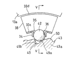
図3乃至図5Bに示すように、小径円筒部33cには内方に突出する複数のポケット筒部34が周方向に等間隔に形成され、各ポケット筒部34内にボール42が組み込まれている。ボール42はポケット筒部34の両端から外周の一部が露出する組み込みとされている。
ポケット筒部34には複数の軸方向のスリット35が周方向に間隔をおいて設けられ、隣接するスリット35間に形成された弾性片36によってボール42が弾性保持されている。
また、環状筒部33には、隣り合うポケット筒部34間にスリット37が形成され、そのスリット37によって、小径円筒部33c、その小径円筒部33cの軸方向両端に連設された外側フランジ部33bの内周部および内側フランジ部33dのそれぞれが周方向に分割されて、内側フランジ部33d側に弾性変形可能な断面コの字状の分割片部38が設けられている。
図1に示すように、カバー31は、環状板部32がプーリ10における環状板12の外側面に衝合する取り付けとされる。
カバー31の取り付けに際し、ここでは、プーリ10の環状板12にナット嵌合孔39を設け、そのナット嵌合孔39にナット40を嵌着し、そのナット40にねじ込まれるビス41の締め付けによりカバー31を取り付けているが、プーリ10の環状板12にねじ孔を直接形成し、そのねじ孔にビス41をねじ込むようにしてもよい。
ハブ43は、円板部43aの一側面に小径軸部43bを設けた構成とされ、上記小径軸部43bの端面で開口する軸孔44が形成されている。ハブ43は、軸孔44内に回転軸21の軸端部に形成された小径軸部21aが嵌合されるようにして小径軸部21a上にセットされ、上記ハブ43の軸心上に形成された挿入孔45から小径軸部21aに設けられたねじ孔46にねじ込まれるボルト47の締め付けによって回転軸21に取り付けられる。このとき、軸孔44と小径軸部21aの嵌合はセレーション48による嵌合とされて回転軸21にハブ43が回り止めされている。
回転軸21に対するハブ43の取り付けによって円板部43aがカバー31の小径側円筒部33c内に収容され、その円板部43aの外径面に複数のV溝49が等ピッチで形成されている。V溝49として、図5Aでは周方向で対向する内側面49a、49bの傾斜角度が相違するものを示したが、図8に示すように、内側面49a、49bの傾斜角度が等しくされたものであってもよい。
また、ハブ43の円板部43aには、図5A、図5Bに示すように、隣り合うV溝間にはボール42をポケット筒部34から径方向外方に押出し可能な押圧部50が設けられている。押圧部50として、ここでは、円弧状の突出部からなるものを示したが、隣り合うV溝49間の円板部43aの外径面を押圧部50としてもよい。
ハブ43は部品コストの低減を図るため、焼結材による成形品としているが、樹脂による成形品としてもよい。
実施の形態で示す動力伝達装置は上記の構造からなり、エンジンからの回転が伝達されてプーリ10が図2の矢印で示す順方向に回転すると、そのプーリ10と共にカバー31が回転し、その回転が図5A、図5Bに示すボール42とV溝49の内側面49aの係合部からハブ43に伝達されて、図1に示す回転軸21が回転し、自動車補機20が作動する。
自動車補機20の負荷変動やエンジンからプーリ10に負荷される回転トルクの変動が生じると、図5Aに示すV溝49の内側面49aからボール42に作用する押圧力により、図5Bに示す分割片部38が内側方に弾性変形し、ボール42がV溝49の内側面49aに沿ってずれ動き、上記分割片部38の弾性変形によるダンパ作用によって自動車補機の負荷変動やエンジンからのトルク変動が吸収される。このため、回転変動が生じたとしても、回転軸21は円滑に回転する。
自動車補機の作動状態において、自動車補機20が故障し、回転軸21の回転負荷が大きくなると、図5Aに示すV溝49の内側面49aからボール42に作用する押圧力により、図5Bに示す分割片部38が内側方に弾性変形して、図6A、図6Bに示すように、内側フランジ部33dの外径縁がボス部13の環状突出部13aの内径面に当接する。その当接状態からプーリ10がさらに同方向に回転することにより、V溝49の内側面49aからボール42に押圧力が作用し、ボール42は径方向外方に向けて移動して内側面49aの外周エッジを乗り上げ、V溝49に対するボール42の係合が解除し、プーリ10から回転軸21への回転伝達が遮断され、プーリ10およびカバー31がフリー回転する。そのプーリ10のフリー回転により、プーリ10に掛かるベルトが過張力になるのが防止される。
また、V溝49に対するボール42の係合解除後、図7A、図7Bに示すように、ボール42は押圧部50に乗り上げ、その押圧部50からの押し込み力の負荷によりボール42は同図の鎖線で示すようにポケット筒部34から抜け出し、プーリ10から回転軸21への回転伝達の遮断状態が保持される。
ここで、ポケット筒部34から抜け出したボール42は図1に示される環状筒部33内に収容される。このため、ボール42の外部への脱落によって周辺機器が損傷し、あるいは、トラブルが発生するという不都合の発生は皆無である。
図9、図10に、本発明に関連する実施形態のリミッタ付きプーリを示す。このリミッタ付きプーリは、プーリ51と、プーリ51の中心に配置されたハブ52と、プーリ51からハブ52に回転トルクを伝達するトルクリミッタ53とを有する。
プーリ51の外周には、駆動ベルト54が巻き掛けられる。駆動ベルト54は、図示しないエンジンのクランクシャフトに連結されており、エンジンが作動してクランクシャフトが回転すると、そのクランクシャフトの回転が駆動ベルト54を介してプーリ51に伝達するようになっている。
プーリ51は、駆動ベルト54に係合する周溝55を外周にもつ筒状のリム部56と、リム部56の内側に配置された筒状のボス部57と、リム部56とボス部57の間を連結する連結部58とを有する。リム部56とボス部57と連結部58は、樹脂で一体に形成されている。ボス部57の内周には、プーリ51を回転可能に支持する転がり軸受59が取り付けられている。転がり軸受59の内側には、自動車補機60(例えば、カーエアコン用のコンプレッサ)に固定される筒状の支持軸61が設けられている。連結部58には、トルクリミッタ53を固定するための金属製のナット62が埋め込まれている。
ハブ52は、プーリ51の回転中心に位置する被駆動軸63の軸端部にボルト64で固定されている。被駆動軸63は、プーリ51の外周に巻き掛けられた駆動ベルト54で回転駆動される軸であり、この被駆動軸63の回転力を動力として自動車補機60が駆動される。ハブ52は、被駆動軸63の軸端部の外周に形成されたスプラインに嵌合するスプライン筒部65と、スプライン筒部65の外周に一体に形成されたフランジ部66とを有する。
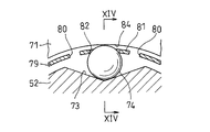
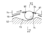
トルクリミッタ53は、第1の円環板71と、第1の円環板71に軸方向に対向して設けられた第2の円環板72と、ハブ52のフランジ部66の外周に形成されたV溝73と、V溝73に収容されたボール74とを有する。第1の円環板71と第2の円環板72は、いずれも金属板で形成され、プーリ51の側面にボルト75で固定されている。V溝73は、周方向に間隔をおいて複数設けられ、これに対応してボール74も複数設けられている。
第1の円環板71は、全体が軸方向に直交する平板状とされている。第2の円環板72は、第1の円環板71の外径側部分に重ねて固定される外側平板部76と、第1の円環板71の内径側部分と軸方向に間隔をおいて平行に配置された内側平板部77と、外側平板部76の径方向内端と内側平板部77の径方向外端を連結する外側円筒部78と、内側平板部77の径方向内端から第1の円環板71に向かって軸方向に延びる内側円筒部79とを有する(図13参照)。
図11に示すように、V溝73は、軸方向に直交する断面形状がV字状の溝であり、径方向深さが周方向中央から周方向両側に向かって次第に浅くなるように形成されている。V溝73は、例えば、軸方向に直交する断面形状が、30°~50°の範囲の角度で交差する2直線となるような溝を採用することができる。ボール74は、V溝73の最も深い位置に収容された状態でV溝73から外径側にはみ出すような大きさの外径を有する。ボール74は、鋼材で形成されている。
図10に示すように、第2の円環板72には、ボール74の個数に対応して複数対のスリット80が形成されている。各対のスリット80は、周方向に間隔をおいて位置する2本のスリットで構成されている。
図13に示すように、各対のスリット80は、内側円筒部79を軸方向に横切り、さらに内側円筒部79と内側平板部77の境界から内側平板部77の内部を径方向外方に延びるように形成されている。内側円筒部79の隣り合うスリット80の間の部分には、軸方向に延びるばね片81が形成されている。ばね片81は、ボール74(図11参照)が径方向外方に移動したときに径方向外方にたわんでボール74に径方向内方への付勢力を付与する部分である。各スリット80の幅は、ボール74の外径よりも狭い大きさに設定されている。
図12に示すように、ばね片81は、ボール74に嵌合する穴部82と、その穴部82の円周を分割する切り離し部83とを有する。穴部82は、ボール74の外径よりも小径の円形縁を有する。切り離し部83は、穴部82の内周から軸方向に延びてばね片81の先端に開放する切り込みである。
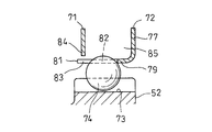
図14A、図14Bに示すように、第1の円環板71は、ばね片81の径方向外方に隙間をおいて位置するストッパ部84(図では第1の円環板71の径方向内端の周縁部)を有する。ばね片81とストッパ部84の間の隙間の大きさは、ボール74の外径よりも狭い。ストッパ部84は、図15A、図15Bに示すように、ばね片81が径方向外方にたわんだときにばね片81を受け止めてばね片81のたわみ量を規制する部分である。
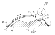
図9に示すように、第1の円環板71と第2の円環板72の対向面間(この参考形態では、第1の円環板71の内径側部分と、第2の円環板72の外側円筒部78と内側平板部77と内側円筒部79とで囲まれた空間)に、ボール収容部85が形成されている。ボール収容部85は、ボール74がばね片81を通過して径方向外方に移動したときにそのボール74を受け入れる空間である。
このリミッタ付きプーリの使用例を説明する。エンジンのクランクシャフトの回転が駆動ベルト54を介してプーリ51に伝達し、プーリ51が回転すると、そのプーリ51の回転がトルクリミッタ53を介してハブ52に伝達することで、被駆動軸63が回転駆動される。ここで、被駆動軸63の回転負荷が通常範囲のとき(すなわち、自動車補機60が破損せずに作動しているとき)、トルクリミッタ53はプーリ51からハブ52に回転トルクを伝達する。
このとき、図15A、図15Bに示すように、プーリ51(図9参照)とハブ52の間に作用する回転トルクに応じて、ボール74がばね片81を径方向外方にたわませながらV溝73に沿って径方向外方に移動し、プーリ51(図9参照)とハブ52が周方向に相対変位する。そのため、図9に示す被駆動軸63の回転負荷の変動や、駆動ベルト54からプーリ51に伝わる回転トルクの変動を、プーリ51とハブ52の間で吸収することができ、ダンパ作用を得ることができる。
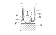
また、図9に示す自動車補機60が万一破損して被駆動軸63の回転負荷が過大となったときは、図16A、図16Bに示すように、ボール74がばね片81の穴部82と切り離し部83とを押し広げて径方向外方に通過し、ボール74がボール収容部85に受け入れられた状態となる。この状態では、V溝73にボール74が無いため、プーリ51(図9参照)とハブ52の間での回転トルクの伝達が遮断される。このように、図9に示すトルクリミッタ53は、被駆動軸63の回転負荷が過大となったときに、プーリ51からハブ52への回転トルクの伝達を遮断することでプーリ51を空転させ、駆動ベルト54を保護することで、修理工場までの自動車の走行を可能とする。
このリミッタ付きプーリは、自動車補機60が破損して被駆動軸63の回転負荷が過大となったときに、プーリ51とハブ52の間での回転トルクの伝達を遮断し、駆動ベルト54を保護する。またこの状態でプーリ51が回転しても、プーリ51の回転に伴って繰り返し衝突する部分が無いため、異音が発生しにくい。
また、このリミッタ付きプーリは、ばね片81が径方向外方にたわんだときにばね片81を受け止めてばね片81のたわみ量を規制するストッパ部84を有するので、ボール74がV溝73に沿って移動することによるダンパ作用を確保しながら、トルクリミッタ53が作動する回転トルクを比較的大きく設定することが可能となっている。
また、このリミッタ付きプーリは、内側円筒部79と内側平板部77の境界から内側平板部77の内部を径方向外方に延びるようにスリット80が形成されているので、ばね片81が弾性変形しやすく、効果的にダンパ作用を得ることが可能となっている。
また、このリミッタ付きプーリは、各スリット80の幅が、ボール74の外径よりも狭い大きさに設定されているので、ボール収容部85がボール74を受け入れたときに、そのボール74がスリット80を通って脱落するのを防止することが可能となっている。
上記実施形態は、以下に付記する発明を開示する。
(付記1)
外周に駆動ベルトが巻き掛けられるプーリと、
前記プーリの回転中心に位置する被駆動軸の軸端部に固定されるハブと、
前記被駆動軸の回転負荷が通常範囲のときは前記プーリから前記ハブに回転トルクを伝達し、前記被駆動軸の回転負荷が過大となったときは前記プーリから前記ハブへの回転トルクの伝達を遮断するトルクリミッタと、
を有するリミッタ付きプーリにおいて、
前記トルクリミッタは、
径方向深さが周方向中央から周方向両側に向かって次第に浅くなるように前記ハブの外周に設けられたV溝と、
前記V溝に収容されたボールと、
前記ボールに嵌合する穴部と、その穴部の円周を分割する切り離し部とを有し、前記ボールが径方向外方に移動したときに径方向外方にたわんで前記ボールに径方向内方への付勢力を付与するばね片と、
前記ボールが前記穴部と前記切り離し部とを押し広げて径方向外方に通過したときにそのボールを受け入れるボール収容部と、
を有することを特徴とするリミッタ付きプーリ。
(付記2)
前記トルクリミッタは、
前記ばね片の径方向外方に隙間をおいて位置し、前記ばね片が径方向外方にたわんだときに前記ばね片を受け止めて前記ばね片のたわみ量を規制するストッパ部を更に有する付記1に記載のリミッタ付きプーリ。
前記トルクリミッタは、
前記ばね片の径方向外方に隙間をおいて位置し、前記ばね片が径方向外方にたわんだときに前記ばね片を受け止めて前記ばね片のたわみ量を規制するストッパ部を更に有する付記1に記載のリミッタ付きプーリ。
(付記3)
前記トルクリミッタは、
前記プーリの側面に固定される第1の円環板と、
前記第1の円環板に軸方向に対向して設けられた第2の円環板とを有し、
前記ばね片は、前記第2の円環板の径方向内端に軸方向に延びるように設けられ、
前記ストッパ部は、前記第1の円環板の径方向内端に設けられ、
前記ボール収容部は、前記第1の円環板と第2の円環板の対向面間に形成された空間である付記2に記載のリミッタ付きプーリ。
前記トルクリミッタは、
前記プーリの側面に固定される第1の円環板と、
前記第1の円環板に軸方向に対向して設けられた第2の円環板とを有し、
前記ばね片は、前記第2の円環板の径方向内端に軸方向に延びるように設けられ、
前記ストッパ部は、前記第1の円環板の径方向内端に設けられ、
前記ボール収容部は、前記第1の円環板と第2の円環板の対向面間に形成された空間である付記2に記載のリミッタ付きプーリ。
(付記4)
前記第2の円環板は、前記第1の円環板と軸方向に間隔をおいて平行に配置された内側平板部と、その内側平板部の径方向内端から第1の円環板に向かって軸方向に延びる内側円筒部と、その内側円筒部を軸方向に横切って形成された少なくとも一対のスリットとを有し、その一対のスリットの間に前記ばね片が形成されている付記3に記載のリミッタ付きプーリ。
前記第2の円環板は、前記第1の円環板と軸方向に間隔をおいて平行に配置された内側平板部と、その内側平板部の径方向内端から第1の円環板に向かって軸方向に延びる内側円筒部と、その内側円筒部を軸方向に横切って形成された少なくとも一対のスリットとを有し、その一対のスリットの間に前記ばね片が形成されている付記3に記載のリミッタ付きプーリ。
(付記5)
前記少なくとも一対のスリットは、前記内側円筒部と前記内側平板部の境界から前記内側平板部の内部を径方向外方に延びるように形成されている付記4に記載のリミッタ付きプーリ。
前記少なくとも一対のスリットは、前記内側円筒部と前記内側平板部の境界から前記内側平板部の内部を径方向外方に延びるように形成されている付記4に記載のリミッタ付きプーリ。
(付記6)
前記少なくとも一対のスリットの各スリットの幅は、前記ボールの外径よりも狭い大きさに設定されている付記4または5に記載のリミッタ付きプーリ。
前記少なくとも一対のスリットの各スリットの幅は、前記ボールの外径よりも狭い大きさに設定されている付記4または5に記載のリミッタ付きプーリ。
10 プーリ
20 自動車補機
21 回転軸
23 プーリ支持軸
30 トルクリミッタ機構
31 カバー
32 環状板部
33a 大径円筒部
33b 外側フランジ部
33c 小径円筒部
33d 内側フランジ部
34 ポケット筒部
35 スリット
36 弾性片
37 スリット
42 ボール
43 ハブ
49 V溝
20 自動車補機
21 回転軸
23 プーリ支持軸
30 トルクリミッタ機構
31 カバー
32 環状板部
33a 大径円筒部
33b 外側フランジ部
33c 小径円筒部
33d 内側フランジ部
34 ポケット筒部
35 スリット
36 弾性片
37 スリット
42 ボール
43 ハブ
49 V溝
Claims (6)
- 自動車補機の回転軸と同軸上に設けられたプーリ支持軸を中心にして回転自在に支持されたプーリと、そのプーリと前記回転軸との間に設けられてプーリの回転を前記回転軸に伝達し、その回転軸の回転負荷が設定値を超えた際にプーリから回転軸への回転伝達を遮断するトルクリミッタ機構とを有してなる動力伝達装置において、
前記トルクリミッタ機構が、前記プーリの外側面に連結された環状のカバーと、そのカバーの内周に保持された複数のボールと、前記回転軸の軸端部に取り付けられたハブとを備え、前記カバーが前記ハブを覆う円筒部を内周に有し、その円筒部にボールの一部が内径側に露出する状態でボールを弾性保持する複数のポケット筒部が周方向に間隔をおいて設けられ、前記ハブの外径面には前記ボールの一部が嵌合するV溝を設けられ、前記ハブの隣接するV溝間にはポケット筒部内から径方向外方に向けてボールに押出し力を負荷する押圧部が設けられた構成とされていることを特徴とする動力伝達装置。 - 前記ポケット筒部に軸方向に延びる複数のスリットが周方向に間隔をおいて形成され、隣接するスリット間に形成された弾性片で前記ボールを弾性保持した請求項1に記載の動力伝達装置。
- 前記カバーが、プーリの外側面に連結される環状板部と、その環状板部の内周から外側方に向く大径円筒部と、その大径円筒部の端部から内径方向に向く外側フランジ部と、その外側フランジ部の内周部から内側方に向く小径円筒部と、その小径円筒部の端部から外径方向に向き、その外径縁が前記プーリに形成されたボス部の内径面と間隙をおいて対向する内側フランジ部とを有してなり、前記小径円筒部に前記ポケット筒部が形成された請求項1および2に記載の動力伝達装置。
- 前記隣り合うポケット筒部間において、小径円筒部、その小径円筒部の軸方向両端に連設された外側フランジ部の内周部および内側フランジ部のそれぞれを周方向に分割するスリットを形成した請求項3に記載の動力伝達装置。
- 前記ハブが焼結材からなる請求項1乃至4のいずれか1項に記載の動力伝達装置。
- 前記ハブが樹脂からなる請求項1乃至4のいずれか1項に記載の動力伝達装置。
Applications Claiming Priority (4)
| Application Number | Priority Date | Filing Date | Title |
|---|---|---|---|
| JP2016043012A JP2017160923A (ja) | 2016-03-07 | 2016-03-07 | 動力伝達装置 |
| JP2016-043012 | 2016-03-07 | ||
| JP2016058466A JP6777411B2 (ja) | 2016-03-23 | 2016-03-23 | リミッタ付きプーリ |
| JP2016-058466 | 2016-03-23 |
Publications (1)
| Publication Number | Publication Date |
|---|---|
| WO2017154794A1 true WO2017154794A1 (ja) | 2017-09-14 |
Family
ID=59790305
Family Applications (1)
| Application Number | Title | Priority Date | Filing Date |
|---|---|---|---|
| PCT/JP2017/008594 WO2017154794A1 (ja) | 2016-03-07 | 2017-03-03 | 動力伝達装置 |
Country Status (1)
| Country | Link |
|---|---|
| WO (1) | WO2017154794A1 (ja) |
Cited By (1)
| Publication number | Priority date | Publication date | Assignee | Title |
|---|---|---|---|---|
| DE102020126988B4 (de) | 2019-10-30 | 2024-04-25 | Airbus Helicopters | Getriebesystem zur Kraftübertragung mit Drehmomentbegrenzung und damit ausgestatteter Prüfstand |
Citations (8)
| Publication number | Priority date | Publication date | Assignee | Title |
|---|---|---|---|---|
| JPS5156458U (ja) * | 1974-10-26 | 1976-05-01 | ||
| JPS5177447U (ja) * | 1974-12-16 | 1976-06-18 | ||
| US4460078A (en) * | 1981-12-10 | 1984-07-17 | Heide Charles H | Torque release clutch |
| JPS6439936U (ja) * | 1987-09-03 | 1989-03-09 | ||
| JP2003074584A (ja) * | 2001-08-30 | 2003-03-12 | Nok Corp | 動力伝達装置 |
| US20060240926A1 (en) * | 2003-05-17 | 2006-10-26 | Bernhard Wiesneth | Device for auxiliary units of an internal combustion engine |
| JP2007187279A (ja) * | 2006-01-16 | 2007-07-26 | Mitsuba Corp | リニアアクチュエータ |
| JP2014092261A (ja) * | 2012-11-07 | 2014-05-19 | Asa Denshi Kogyo Kk | ジョイント |
-
2017
- 2017-03-03 WO PCT/JP2017/008594 patent/WO2017154794A1/ja active Application Filing
Patent Citations (8)
| Publication number | Priority date | Publication date | Assignee | Title |
|---|---|---|---|---|
| JPS5156458U (ja) * | 1974-10-26 | 1976-05-01 | ||
| JPS5177447U (ja) * | 1974-12-16 | 1976-06-18 | ||
| US4460078A (en) * | 1981-12-10 | 1984-07-17 | Heide Charles H | Torque release clutch |
| JPS6439936U (ja) * | 1987-09-03 | 1989-03-09 | ||
| JP2003074584A (ja) * | 2001-08-30 | 2003-03-12 | Nok Corp | 動力伝達装置 |
| US20060240926A1 (en) * | 2003-05-17 | 2006-10-26 | Bernhard Wiesneth | Device for auxiliary units of an internal combustion engine |
| JP2007187279A (ja) * | 2006-01-16 | 2007-07-26 | Mitsuba Corp | リニアアクチュエータ |
| JP2014092261A (ja) * | 2012-11-07 | 2014-05-19 | Asa Denshi Kogyo Kk | ジョイント |
Cited By (1)
| Publication number | Priority date | Publication date | Assignee | Title |
|---|---|---|---|---|
| DE102020126988B4 (de) | 2019-10-30 | 2024-04-25 | Airbus Helicopters | Getriebesystem zur Kraftübertragung mit Drehmomentbegrenzung und damit ausgestatteter Prüfstand |
Similar Documents
| Publication | Publication Date | Title |
|---|---|---|
| US7878315B2 (en) | Spring clutch | |
| JP3578687B2 (ja) | トルクを内燃機関から圧縮機に伝達する装置 | |
| JP4838164B2 (ja) | 動力伝達装置 | |
| JP5758687B2 (ja) | 遠心クラッチ装置 | |
| WO2012176573A1 (ja) | 動力伝達装置及び動力伝達装置を備えた圧縮機 | |
| JP2008267563A (ja) | スプリングクラッチ | |
| WO2017154794A1 (ja) | 動力伝達装置 | |
| EP0507212B1 (en) | Torque variation absorbing device | |
| US9611904B2 (en) | Centrifugal clutch apparatus | |
| JP4533272B2 (ja) | 動力伝達装置 | |
| JP2005330991A (ja) | 圧縮機の動力伝達装置 | |
| JP2008019959A (ja) | スプリングクラッチ | |
| JP4853105B2 (ja) | 一方向クラッチ内蔵型プーリ装置 | |
| JP4298574B2 (ja) | 動力伝達装置 | |
| JP2011169397A (ja) | プーリユニット | |
| KR101549330B1 (ko) | 토크 전달 장치의 댐퍼 기구 | |
| JP2017160923A (ja) | 動力伝達装置 | |
| JP6777411B2 (ja) | リミッタ付きプーリ | |
| JP4506783B2 (ja) | 動力伝達装置用ハブ | |
| JP2006170398A (ja) | 動力伝達装置 | |
| JP2007333051A (ja) | スプリングクラッチ | |
| JP2007205379A (ja) | プーリ | |
| JP2005289255A (ja) | 車両用駆動輪ハブユニット | |
| JP2017155877A (ja) | 動力伝達装置 | |
| JP5353869B2 (ja) | 自動車の補機用一方向クラッチ内蔵型プーリ装置 |
Legal Events
| Date | Code | Title | Description |
|---|---|---|---|
| NENP | Non-entry into the national phase |
Ref country code: DE |
|
| 121 | Ep: the epo has been informed by wipo that ep was designated in this application |
Ref document number: 17763134 Country of ref document: EP Kind code of ref document: A1 |
|
| 122 | Ep: pct application non-entry in european phase |
Ref document number: 17763134 Country of ref document: EP Kind code of ref document: A1 |