WO2017154794A1 - Dispositif de transmission de puissance - Google Patents
Dispositif de transmission de puissance Download PDFInfo
- Publication number
- WO2017154794A1 WO2017154794A1 PCT/JP2017/008594 JP2017008594W WO2017154794A1 WO 2017154794 A1 WO2017154794 A1 WO 2017154794A1 JP 2017008594 W JP2017008594 W JP 2017008594W WO 2017154794 A1 WO2017154794 A1 WO 2017154794A1
- Authority
- WO
- WIPO (PCT)
- Prior art keywords
- pulley
- hub
- ball
- cylindrical portion
- diameter
- Prior art date
Links
Images


Classifications
-
- F—MECHANICAL ENGINEERING; LIGHTING; HEATING; WEAPONS; BLASTING
- F16—ENGINEERING ELEMENTS AND UNITS; GENERAL MEASURES FOR PRODUCING AND MAINTAINING EFFECTIVE FUNCTIONING OF MACHINES OR INSTALLATIONS; THERMAL INSULATION IN GENERAL
- F16D—COUPLINGS FOR TRANSMITTING ROTATION; CLUTCHES; BRAKES
- F16D7/00—Slip couplings, e.g. slipping on overload, for absorbing shock
- F16D7/04—Slip couplings, e.g. slipping on overload, for absorbing shock of the ratchet type
- F16D7/06—Slip couplings, e.g. slipping on overload, for absorbing shock of the ratchet type with intermediate balls or rollers
- F16D7/10—Slip couplings, e.g. slipping on overload, for absorbing shock of the ratchet type with intermediate balls or rollers moving radially between engagement and disengagement
-
- F—MECHANICAL ENGINEERING; LIGHTING; HEATING; WEAPONS; BLASTING
- F16—ENGINEERING ELEMENTS AND UNITS; GENERAL MEASURES FOR PRODUCING AND MAINTAINING EFFECTIVE FUNCTIONING OF MACHINES OR INSTALLATIONS; THERMAL INSULATION IN GENERAL
- F16D—COUPLINGS FOR TRANSMITTING ROTATION; CLUTCHES; BRAKES
- F16D43/00—Automatic clutches
- F16D43/02—Automatic clutches actuated entirely mechanically
- F16D43/20—Automatic clutches actuated entirely mechanically controlled by torque, e.g. overload-release clutches, slip-clutches with means by which torque varies the clutching pressure
- F16D43/202—Automatic clutches actuated entirely mechanically controlled by torque, e.g. overload-release clutches, slip-clutches with means by which torque varies the clutching pressure of the ratchet type
- F16D43/204—Automatic clutches actuated entirely mechanically controlled by torque, e.g. overload-release clutches, slip-clutches with means by which torque varies the clutching pressure of the ratchet type with intermediate balls or rollers
- F16D43/208—Automatic clutches actuated entirely mechanically controlled by torque, e.g. overload-release clutches, slip-clutches with means by which torque varies the clutching pressure of the ratchet type with intermediate balls or rollers moving radially between engagement and disengagement
-
- F—MECHANICAL ENGINEERING; LIGHTING; HEATING; WEAPONS; BLASTING
- F16—ENGINEERING ELEMENTS AND UNITS; GENERAL MEASURES FOR PRODUCING AND MAINTAINING EFFECTIVE FUNCTIONING OF MACHINES OR INSTALLATIONS; THERMAL INSULATION IN GENERAL
- F16H—GEARING
- F16H55/00—Elements with teeth or friction surfaces for conveying motion; Worms, pulleys or sheaves for gearing mechanisms
- F16H55/32—Friction members
- F16H55/36—Pulleys
Definitions
- the present invention relates to a power transmission device that transmits power from an engine to an automobile auxiliary machine.
- Patent Document 1 proposes a power transmission device having a torque limiter mechanism.
- a pulley for transmitting engine power via a belt a hub attached to a rotating shaft of a compressor, and a torque limiter mechanism provided between the hub and the pulley. And have.
- the torque limiter mechanism connects one end of an arc-shaped connecting member to a pulley, and the other end of the connecting member is provided with a slit having a wide portion that opens at the end of the connecting member.
- a columnar body formed by a rivet that penetrates the flange of the hub and a collar through which the rivet penetrates is provided, the columnar body is inserted into the wide portion of the slit, and a disc spring is incorporated between the hub and the connecting member.
- An object of the present invention is to provide a power transmission device that generates less noise during operation of a torque limiter mechanism.
- a pulley supported rotatably around a pulley support shaft provided coaxially with a rotation shaft of an automobile accessory, and the pulley and the rotation shaft
- a torque limiter mechanism which is provided between the pulley and transmits the rotation of the pulley to the rotating shaft and cuts off the rotation transmission from the pulley to the rotating shaft when the rotational load of the rotating shaft exceeds a set value.
- the torque limiter mechanism is attached to an annular cover connected to the outer surface of the pulley, a plurality of balls held on the inner periphery of the cover, and a shaft end of the rotating shaft.
- a plurality of pocket tube portions that elastically hold the ball in a state in which a part of the ball is exposed to the inner diameter side in the cylindrical portion. Set at intervals.
- a V groove into which a part of the ball is fitted is provided on the outer diameter surface of the hub, and the pushing force to the ball is directed radially outward from the inside of the pocket cylindrical portion between the adjacent V grooves of the hub. It is set as the structure provided with the press part which loads.
- the cover rotates together with the pulley, and the rotation is transmitted to the hub from the ball held by the cover and the engaging portion of the V groove formed on the outer periphery of the hub.
- the rotating shaft rotates and the automobile auxiliary machine operates.
- the ball When there is a change in the load of an automobile accessory or a change in rotational torque applied to the pulley from the engine, the ball is displaced in the pocket cylinder by the pressing force applied to the ball from the inclined inner surface of the V groove, and the movement As a result, the pocket tube portion is elastically deformed to absorb the torque fluctuation.
- a plurality of slits extending in the axial direction are formed in the pocket cylindrical portion at intervals in the circumferential direction, and the pocket cylindrical portion is elastically deformed by elastically holding the ball with an elastic piece formed between adjacent slits. This makes it easy to obtain a good damper effect.
- the cover formed with the pocket cylindrical portion for holding the ball includes an annular plate portion connected to the outer surface of the pulley, a large-diameter cylindrical portion facing outward from the inner periphery of the annular plate portion, and the large-diameter cylindrical portion.
- the pulley has an inner flange portion facing the inner diameter surface of the boss portion formed on the pulley with a gap, and the pocket cylindrical portion is formed on the small diameter cylindrical portion.
- annular space is formed by the large diameter cylindrical portion, the outer flange portion, the small diameter cylindrical portion, and the inner flange portion, and the ball pushed out from the pocket cylindrical portion is held in the annular space. It will be. As a result, it is possible to prevent the peripheral device from being damaged or causing troubles due to the falling of the ball to the outside.
- each of the inner peripheral portion and the inner flange portion of the outer flange portion connected to both ends in the axial direction of the small-diameter cylindrical portion and the small-diameter cylindrical portion is divided between adjacent pocket cylindrical portions in the circumferential direction. If the slits are formed, elasticity can be imparted to the divided pieces between the adjacent slits, so that the ball can move smoothly with respect to the inner surface of the V-groove.
- the hub material should be sintered or resin.
- the hub can be easily formed by molding, and a low-cost hub can be obtained.
- the ball moves in the pocket cylinder part and the automobile auxiliary element is elastically deformed by the pocket cylinder part due to the deviation movement. It is possible to absorb the load fluctuation of the machine and the torque fluctuation from the engine, and to smoothly drive the automobile auxiliary machine.
- FIG. 9 is a right side view of the pulley with limiter shown in Fig. 9.
- Sectional view along line XI-XI in Fig. 9 Sectional view along line XII-XII in FIG.
- Sectional view along line XIV-XIV in Fig. 14A The figure which shows the state which the ball
- the power transmission device includes a pulley 10 to which power from an engine (not shown) is transmitted, a rotating shaft 21 of an automobile auxiliary machine 20, and a mutual connection between the pulley 10 and the rotating shaft 21.
- the torque limiter mechanism 30 is provided between the pulley 10 and the rotation of the pulley 10 so as to transmit the rotation to the rotation shaft 21 and cut off the rotation transmission from the pulley 10 to the rotation shaft 21 when the rotation load of the rotation shaft 21 increases.
- the pulley 10 has a belt guide wheel 11, an annular plate 12 provided on the inner periphery of the belt guide wheel 11, and a cylindrical boss portion 13 provided on the inner periphery of the annular plate 12.
- a pair of flanges 14 are provided on both sides of the outer periphery of the guide wheel 11, and a plurality of V-shaped grooves 15 around which the V belt is wound are provided between the pair of flanges 14.
- a bearing housing 16 is incorporated inside the boss 13.
- the bearing housing 16 is secured by an annular projecting portion 13 a provided on the inner periphery of one end of the boss portion 13.
- the bearing housing 16 is prevented from rotating by a serration 17 formed on the outer periphery of one end and the inner periphery of one end of the boss portion 13, and a rolling bearing 18 is incorporated in the bearing housing 16.
- a double row ball bearing is employed as the rolling bearing 18.
- the rolling bearing 18 is press-fitted into a cylindrical pulley support shaft 23 provided in the housing 22 of the automobile auxiliary machine 20 and is prevented from being removed by a retaining ring 24 attached to the outer periphery of the end of the pulley support shaft 23.
- a compressor for an air conditioner is employed as the automobile auxiliary machine 20.
- the pulley support shaft 23 provided on the housing 22 of the automobile auxiliary machine 20 is provided coaxially with the rotary shaft 21, and the pulley 10 is supported rotatably about the pulley support shaft 23.
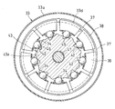
- the torque limiter mechanism 30 includes an annular cover 31 provided on the outer surface of the pulley 10, a plurality of balls 42 held on the inner periphery of the cover 31, and a hub 43 attached to the shaft end of the rotating shaft 21. It consists of.
- the cover 31 is made of a press-formed product of a metal plate provided with an annular cylindrical portion 33 on the inner periphery of the annular plate portion 32.
- the annular cylindrical portion 33 has a bowl-shaped cross section, and has a large-diameter cylindrical portion 33a facing outward from the inner periphery of the annular plate portion 32, and an outer flange portion 33b facing radially inward from the end of the large-diameter cylindrical portion 33a.
- the small-diameter cylindrical portion 33c which is a cylindrical portion facing inward from the inner peripheral portion of the outer flange portion 33b, and the inner flange portion 33d facing in the outer-diameter direction from the end portion of the small-diameter cylindrical portion 33c.
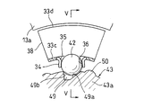
- the small-diameter cylindrical portion 33c is formed with a plurality of pocket cylindrical portions 34 protruding inward at equal intervals in the circumferential direction, and balls 42 are incorporated in the pocket cylindrical portions 34. Yes.
- the ball 42 is incorporated so that a part of the outer periphery is exposed from both ends of the pocket cylindrical portion 34.
- a plurality of axial slits 35 are provided in the pocket cylinder portion 34 at intervals in the circumferential direction, and the balls 42 are elastically held by elastic pieces 36 formed between the adjacent slits 35.
- the annular cylindrical portion 33 is formed with a slit 37 between adjacent pocket cylindrical portions 34, and the slit 37 forms a small diameter cylindrical portion 33 c and an outer flange portion connected to both axial ends of the small diameter cylindrical portion 33 c.
- Each of the inner peripheral portion 33d and the inner flange portion 33d is divided in the circumferential direction, and a U-shaped divided piece portion 38 that can be elastically deformed is provided on the inner flange portion 33d side.
- the cover 31 is attached so that the annular plate portion 32 abuts the outer surface of the annular plate 12 in the pulley 10.
- a nut fitting hole 39 is provided in the annular plate 12 of the pulley 10
- a nut 40 is fitted in the nut fitting hole 39, and a screw 41 screwed into the nut 40 is tightened to cover the cover 31.
- 31 is attached, but a screw hole may be directly formed in the annular plate 12 of the pulley 10, and the screw 41 may be screwed into the screw hole.
- the hub 43 has a configuration in which a small-diameter shaft portion 43b is provided on one side surface of the disc portion 43a, and a shaft hole 44 that opens at an end surface of the small-diameter shaft portion 43b is formed.
- the hub 43 is set on the small-diameter shaft portion 21 a so that the small-diameter shaft portion 21 a formed at the shaft end portion of the rotary shaft 21 is fitted in the shaft hole 44, and is formed on the shaft center of the hub 43.
- the bolt 47 is screwed into the screw hole 46 provided in the small-diameter shaft portion 21a from the inserted insertion hole 45 and attached to the rotary shaft 21. At this time, the shaft hole 44 and the small-diameter shaft portion 21a are fitted by a serration 48, and the hub 43 is prevented from rotating around the rotary shaft 21.
- the disc portion 43a is accommodated in the small diameter side cylindrical portion 33c of the cover 31, and a plurality of V grooves 49 are formed at equal pitches on the outer diameter surface of the disc portion 43a.
- the V-grooves 49 have different inclination angles of the inner side surfaces 49a and 49b facing each other in the circumferential direction.
- the inner side surfaces 49a and 49b have the same inclination angle. It may be.
- the disc portion 43a of the hub 43 is provided with a pressing portion 50 that can push the ball 42 radially outward from the pocket cylindrical portion 34 between adjacent V grooves. It has been.
- the pressing portion 50 is composed of an arcuate protrusion, but the outer diameter surface of the disk portion 43a between the adjacent V grooves 49 may be used as the pressing portion 50.
- the hub 43 is a molded product made of a sintered material in order to reduce component costs, but may be a molded product made of resin.
- the power transmission device shown in the embodiment has the above-described structure.
- the pulley 10 rotates in the forward direction indicated by the arrow in FIG. Is transmitted to the hub 43 from the engaging portion between the ball 42 and the inner surface 49a of the V-groove 49 shown in FIGS. 5A and 5B, the rotating shaft 21 shown in FIG. 1 rotates, and the automobile auxiliary machine 20 operates.
- the ball 42 that has slipped out of the pocket cylindrical portion 34 is accommodated in the annular cylindrical portion 33 shown in FIG. For this reason, there is no inconvenience that the peripheral device is damaged or trouble occurs due to the drop of the ball 42 to the outside.
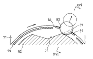
- This pulley with a limiter includes a pulley 51, a hub 52 disposed at the center of the pulley 51, and a torque limiter 53 that transmits rotational torque from the pulley 51 to the hub 52.
- a drive belt 54 is wound around the outer periphery of the pulley 51.
- the drive belt 54 is connected to a crankshaft of an engine (not shown). When the engine operates and the crankshaft rotates, the rotation of the crankshaft is transmitted to the pulley 51 via the drive belt 54. .
- the pulley 51 includes a cylindrical rim portion 56 having a circumferential groove 55 that engages with the drive belt 54 on the outer periphery, a cylindrical boss portion 57 disposed inside the rim portion 56, a rim portion 56, and a boss portion 57. And a connecting portion 58 for connecting the two.
- the rim portion 56, the boss portion 57, and the connecting portion 58 are integrally formed of resin.
- a rolling bearing 59 that rotatably supports the pulley 51 is attached to the inner periphery of the boss portion 57. Inside the rolling bearing 59, a cylindrical support shaft 61 is provided that is fixed to an automobile accessory 60 (for example, a compressor for a car air conditioner).
- a metal nut 62 for fixing the torque limiter 53 is embedded in the connecting portion 58.
- the hub 52 is fixed to the shaft end portion of the driven shaft 63 located at the rotation center of the pulley 51 with a bolt 64.
- the driven shaft 63 is a shaft that is rotationally driven by a drive belt 54 wound around the outer periphery of the pulley 51, and the automobile auxiliary device 60 is driven using the rotational force of the driven shaft 63 as power.
- the hub 52 includes a spline cylinder portion 65 that fits a spline formed on the outer periphery of the shaft end portion of the driven shaft 63, and a flange portion 66 that is integrally formed on the outer periphery of the spline cylinder portion 65.
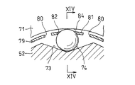
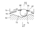
- the torque limiter 53 is formed on the outer periphery of the first annular plate 71, the second annular plate 72 provided to face the first annular plate 71 in the axial direction, and the flange portion 66 of the hub 52. And a ball 74 accommodated in the V-groove 73.
- Each of the first annular plate 71 and the second annular plate 72 is formed of a metal plate, and is fixed to the side surface of the pulley 51 with a bolt 75.
- a plurality of V grooves 73 are provided at intervals in the circumferential direction, and a plurality of balls 74 are also provided correspondingly.
- the first annular plate 71 has a flat plate shape that is orthogonal to the axial direction as a whole.
- the second annular plate 72 is spaced apart from the outer flat plate portion 76 fixed to the outer diameter side portion of the first annular plate 71 and the inner diameter side portion of the first annular plate 71 in the axial direction.
- the inner flat plate portion 77 arranged in parallel, the outer cylindrical portion 78 connecting the radial inner end of the outer flat plate portion 76 and the radial outer end of the inner flat plate portion 77, and the radial inner end of the inner flat plate portion 77.
- an inner cylindrical portion 79 extending in the axial direction toward the first annular plate 71 (see FIG. 13).
- the V-groove 73 is a groove having a V-shaped cross-section perpendicular to the axial direction, and is formed such that the radial depth gradually decreases from the center in the circumferential direction toward both sides in the circumferential direction. ing.
- a groove in which a cross-sectional shape orthogonal to the axial direction forms two straight lines that intersect at an angle in the range of 30 ° to 50 ° can be employed.
- the ball 74 has an outer diameter such that it protrudes from the V groove 73 to the outer diameter side in a state of being accommodated in the deepest position of the V groove 73.
- the ball 74 is made of steel.
- the second annular plate 72 has a plurality of pairs of slits 80 corresponding to the number of balls 74.
- Each pair of slits 80 is composed of two slits positioned at intervals in the circumferential direction.
- each pair of slits 80 crosses the inner cylindrical portion 79 in the axial direction, and further extends radially outward from the boundary between the inner cylindrical portion 79 and the inner flat plate portion 77 in the inner flat plate portion 77. It is formed as follows.
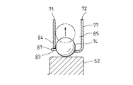
- a spring piece 81 extending in the axial direction is formed in a portion between adjacent slits 80 of the inner cylindrical portion 79.
- the spring piece 81 is a portion that bends radially outward when the ball 74 (see FIG. 11) moves radially outward and applies a radially inward biasing force to the ball 74.
- the width of each slit 80 is set to be smaller than the outer diameter of the ball 74.
- the spring piece 81 has a hole portion 82 that fits into the ball 74 and a separation portion 83 that divides the circumference of the hole portion 82.
- the hole portion 82 has a circular edge having a smaller diameter than the outer diameter of the ball 74.
- the separation part 83 is a cut that extends in the axial direction from the inner periphery of the hole part 82 and opens to the tip of the spring piece 81.
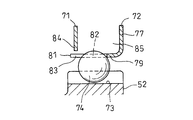
- the first annular plate 71 has a stopper portion 84 (in the drawing, the radial direction of the first annular plate 71 in the figure) that is positioned with a gap radially outward of the spring piece 81. A peripheral edge of the inner end). The size of the gap between the spring piece 81 and the stopper portion 84 is narrower than the outer diameter of the ball 74.
- the stopper portion 84 is a portion that receives the spring piece 81 and regulates the amount of deflection of the spring piece 81 when the spring piece 81 bends radially outward.
- a ball housing portion 85 is formed in a space surrounded by the outer cylindrical portion 78, the inner flat plate portion 77, and the inner cylindrical portion 79 of the plate 72.
- the ball accommodating portion 85 is a space that receives the ball 74 when the ball 74 passes the spring piece 81 and moves radially outward.
- the ball 74 deflects the spring piece 81 radially outward in accordance with the rotational torque acting between the pulley 51 (see FIG. 9) and the hub 52.
- the pulley 51 (see FIG. 9) and the hub 52 are relatively displaced in the circumferential direction by moving radially outward along the V-groove 73. Therefore, the fluctuation of the rotational load of the driven shaft 63 shown in FIG. 9 and the fluctuation of the rotational torque transmitted from the driving belt 54 to the pulley 51 can be absorbed between the pulley 51 and the hub 52 to obtain a damper action. Can do.
- the balls 74 are formed in the holes of the spring pieces 81 as shown in FIGS. 16A and 16B. 82 and the separation part 83 are pushed and spread outward in the radial direction, and the ball 74 is received in the ball accommodating part 85. In this state, since there is no ball 74 in the V-groove 73, transmission of rotational torque between the pulley 51 (see FIG. 9) and the hub 52 is interrupted. As described above, when the rotational load of the driven shaft 63 becomes excessive, the torque limiter 53 shown in FIG. 9 idles the pulley 51 by interrupting the transmission of the rotational torque from the pulley 51 to the hub 52. By protecting the drive belt 54, the vehicle can travel to the repair shop.
- This pulley with a limiter cuts off the transmission of rotational torque between the pulley 51 and the hub 52 when the automobile accessory 60 is damaged and the rotational load of the driven shaft 63 becomes excessive, and the drive belt 54 is Protect. Further, even if the pulley 51 rotates in this state, there is no portion that repeatedly collides with the rotation of the pulley 51, so that abnormal noise is unlikely to occur.
- this pulley with a limiter has a stopper portion 84 that receives the spring piece 81 and regulates the amount of deflection of the spring piece 81 when the spring piece 81 bends radially outward. It is possible to set the rotational torque at which the torque limiter 53 operates to be relatively large while ensuring a damper action by moving along.
- the slit 80 is formed so as to extend radially outward from the boundary between the inner cylindrical portion 79 and the inner flat plate portion 77, the spring piece 81 is elastically deformed. This makes it possible to obtain a damper action effectively.
- each slit 80 is set to be smaller than the outer diameter of the ball 74, when the ball receiving portion 85 receives the ball 74, the ball 74 is slit. It is possible to prevent dropping through 80.
- a torque limiter that shuts off In a pulley with a limiter having The torque limiter is A V-groove provided on the outer periphery of the hub such that the radial depth gradually decreases from the circumferential center toward both sides in the circumferential direction; A ball housed in the V-groove; A hole that fits into the ball and a cut-out portion that divides the circumference of the hole, and the ball deflects radially outward when the ball moves radially outward; A spring piece for applying an inward biasing force; A ball housing portion that receives the ball when the ball has passed through the hole portion and the cut-out portion and radially outward; A pulley with a limiter.
- the torque limiter is Additional notes further comprising a stopper portion that is positioned with a gap radially outward of the spring piece, and that receives the spring piece and regulates the amount of deflection of the spring piece when the spring piece is deflected radially outward.
- the pulley with a limiter according to 1.
- the torque limiter is A first annular plate fixed to a side surface of the pulley; A second annular plate provided in the first annular plate so as to face the axial direction; The spring piece is provided to extend in the axial direction at the radially inner end of the second annular plate, The stopper portion is provided at a radially inner end of the first annular plate,
- the pulley with limiter according to appendix 2 wherein the ball housing portion is a space formed between opposing surfaces of the first annular plate and the second annular plate.
- the second annular plate includes an inner flat plate portion arranged in parallel with the first annular plate at an axial interval, and a first annular plate from a radially inner end of the inner flat plate portion. And an inner cylindrical portion that extends in the axial direction toward the surface, and at least a pair of slits that are formed across the inner cylindrical portion in the axial direction, and the spring piece is formed between the pair of slits. 3.
Abstract
L'invention concerne un mécanisme de limiteur de couple (30) disposé entre une poulie (10) et un arbre rotatif (21) d'une machine auxiliaire d'automobile (20), lequel mécanisme est formé par un capot annulaire (31) relié à la face latérale externe de la poulie (10), une pluralité de billes (42) maintenues dans la périphérie interne du capot (31), et un moyeu (43) attaché à une partie d'extrémité d'arbre de l'arbre rotatif. Une partie cylindrique (33c) qui recouvre le moyeu (43) est disposée sur le capot (31), une partie de tube de poche (34) qui maintient élastiquement les billes (42) est disposée dans la partie cylindrique (33c), une rainure en V (49) est réalisée sur la face de diamètre externe du moyeu (43), les billes (42) viennent en prise dans la rainure en V (49), et la rotation de la poulie (10) est transmise à l'arbre rotatif (21) par ladite section de prise. Quand la machine auxiliaire d'automobile (20) dysfonctionne et que l'arbre rotatif (21) est soumis à charge de rotation importante, une force de pression est appliquée aux billes (42) à partir de la face de côté interne de la rainure en V (49), les billes (42) sont déplacées le long de la face de côté interne de la rainure en V (49) de façon à désolidariser les billes (42) de la rainure en V (49), et la transmission de rotation à partir de la poulie (10) jusqu'à l'arbre rotatif (21) est interrompue.
Applications Claiming Priority (4)
| Application Number | Priority Date | Filing Date | Title |
|---|---|---|---|
| JP2016043012A JP2017160923A (ja) | 2016-03-07 | 2016-03-07 | 動力伝達装置 |
| JP2016-043012 | 2016-03-07 | ||
| JP2016-058466 | 2016-03-23 | ||
| JP2016058466A JP6777411B2 (ja) | 2016-03-23 | 2016-03-23 | リミッタ付きプーリ |
Publications (1)
| Publication Number | Publication Date |
|---|---|
| WO2017154794A1 true WO2017154794A1 (fr) | 2017-09-14 |
Family
ID=59790305
Family Applications (1)
| Application Number | Title | Priority Date | Filing Date |
|---|---|---|---|
| PCT/JP2017/008594 WO2017154794A1 (fr) | 2016-03-07 | 2017-03-03 | Dispositif de transmission de puissance |
Country Status (1)
| Country | Link |
|---|---|
| WO (1) | WO2017154794A1 (fr) |
Cited By (1)
| Publication number | Priority date | Publication date | Assignee | Title |
|---|---|---|---|---|
| DE102020126988B4 (de) | 2019-10-30 | 2024-04-25 | Airbus Helicopters | Getriebesystem zur Kraftübertragung mit Drehmomentbegrenzung und damit ausgestatteter Prüfstand |
Citations (8)
| Publication number | Priority date | Publication date | Assignee | Title |
|---|---|---|---|---|
| JPS5156458U (fr) * | 1974-10-26 | 1976-05-01 | ||
| JPS5177447U (fr) * | 1974-12-16 | 1976-06-18 | ||
| US4460078A (en) * | 1981-12-10 | 1984-07-17 | Heide Charles H | Torque release clutch |
| JPS6439936U (fr) * | 1987-09-03 | 1989-03-09 | ||
| JP2003074584A (ja) * | 2001-08-30 | 2003-03-12 | Nok Corp | 動力伝達装置 |
| US20060240926A1 (en) * | 2003-05-17 | 2006-10-26 | Bernhard Wiesneth | Device for auxiliary units of an internal combustion engine |
| JP2007187279A (ja) * | 2006-01-16 | 2007-07-26 | Mitsuba Corp | リニアアクチュエータ |
| JP2014092261A (ja) * | 2012-11-07 | 2014-05-19 | Asa Denshi Kogyo Kk | ジョイント |
-
2017
- 2017-03-03 WO PCT/JP2017/008594 patent/WO2017154794A1/fr active Application Filing
Patent Citations (8)
| Publication number | Priority date | Publication date | Assignee | Title |
|---|---|---|---|---|
| JPS5156458U (fr) * | 1974-10-26 | 1976-05-01 | ||
| JPS5177447U (fr) * | 1974-12-16 | 1976-06-18 | ||
| US4460078A (en) * | 1981-12-10 | 1984-07-17 | Heide Charles H | Torque release clutch |
| JPS6439936U (fr) * | 1987-09-03 | 1989-03-09 | ||
| JP2003074584A (ja) * | 2001-08-30 | 2003-03-12 | Nok Corp | 動力伝達装置 |
| US20060240926A1 (en) * | 2003-05-17 | 2006-10-26 | Bernhard Wiesneth | Device for auxiliary units of an internal combustion engine |
| JP2007187279A (ja) * | 2006-01-16 | 2007-07-26 | Mitsuba Corp | リニアアクチュエータ |
| JP2014092261A (ja) * | 2012-11-07 | 2014-05-19 | Asa Denshi Kogyo Kk | ジョイント |
Cited By (1)
| Publication number | Priority date | Publication date | Assignee | Title |
|---|---|---|---|---|
| DE102020126988B4 (de) | 2019-10-30 | 2024-04-25 | Airbus Helicopters | Getriebesystem zur Kraftübertragung mit Drehmomentbegrenzung und damit ausgestatteter Prüfstand |
Similar Documents
| Publication | Publication Date | Title |
|---|---|---|
| US7878315B2 (en) | Spring clutch | |
| JP3578687B2 (ja) | トルクを内燃機関から圧縮機に伝達する装置 | |
| JP4838164B2 (ja) | 動力伝達装置 | |
| JP5758687B2 (ja) | 遠心クラッチ装置 | |
| WO2012176573A1 (fr) | Dispositif de transmission d'énergie et compresseur équipé d'un dispositif de transmission d'énergie | |
| JP2008267563A (ja) | スプリングクラッチ | |
| WO2017154794A1 (fr) | Dispositif de transmission de puissance | |
| EP0507212B1 (fr) | Dispositif d'absorption de variations de couple | |
| US9611904B2 (en) | Centrifugal clutch apparatus | |
| JP4533272B2 (ja) | 動力伝達装置 | |
| JP2005330991A (ja) | 圧縮機の動力伝達装置 | |
| JP2008019959A (ja) | スプリングクラッチ | |
| JP4853105B2 (ja) | 一方向クラッチ内蔵型プーリ装置 | |
| JP4298574B2 (ja) | 動力伝達装置 | |
| JP2011169397A (ja) | プーリユニット | |
| KR101549330B1 (ko) | 토크 전달 장치의 댐퍼 기구 | |
| JP2017160923A (ja) | 動力伝達装置 | |
| JP6777411B2 (ja) | リミッタ付きプーリ | |
| JP4506783B2 (ja) | 動力伝達装置用ハブ | |
| JP2006170398A (ja) | 動力伝達装置 | |
| JP2007333051A (ja) | スプリングクラッチ | |
| JP2007205379A (ja) | プーリ | |
| JP2005289255A (ja) | 車両用駆動輪ハブユニット | |
| JP2017155877A (ja) | 動力伝達装置 | |
| JP5353869B2 (ja) | 自動車の補機用一方向クラッチ内蔵型プーリ装置 |
Legal Events
| Date | Code | Title | Description |
|---|---|---|---|
| NENP | Non-entry into the national phase |
Ref country code: DE |
|
| 121 | Ep: the epo has been informed by wipo that ep was designated in this application |
Ref document number: 17763134 Country of ref document: EP Kind code of ref document: A1 |
|
| 122 | Ep: pct application non-entry in european phase |
Ref document number: 17763134 Country of ref document: EP Kind code of ref document: A1 |