WO2017154602A1 - 冷凍サイクル装置 - Google Patents
冷凍サイクル装置 Download PDFInfo
- Publication number
- WO2017154602A1 WO2017154602A1 PCT/JP2017/006965 JP2017006965W WO2017154602A1 WO 2017154602 A1 WO2017154602 A1 WO 2017154602A1 JP 2017006965 W JP2017006965 W JP 2017006965W WO 2017154602 A1 WO2017154602 A1 WO 2017154602A1
- Authority
- WO
- WIPO (PCT)
- Prior art keywords
- heat exchanger
- pressure side
- heat
- refrigerant
- low
- Prior art date
- Legal status (The legal status is an assumption and is not a legal conclusion. Google has not performed a legal analysis and makes no representation as to the accuracy of the status listed.)
- Ceased
Links
Images


Classifications
-
- B—PERFORMING OPERATIONS; TRANSPORTING
- B60—VEHICLES IN GENERAL
- B60H—ARRANGEMENTS OF HEATING, COOLING, VENTILATING OR OTHER AIR-TREATING DEVICES SPECIALLY ADAPTED FOR PASSENGER OR GOODS SPACES OF VEHICLES
- B60H1/00—Heating, cooling or ventilating devices
- B60H1/00642—Control systems or circuits; Control members or indication devices for heating, cooling or ventilating devices
- B60H1/00814—Control systems or circuits characterised by their output, for controlling particular components of the heating, cooling or ventilating installation
- B60H1/00878—Control systems or circuits characterised by their output, for controlling particular components of the heating, cooling or ventilating installation the components being temperature regulating devices
- B60H1/00899—Controlling the flow of liquid in a heat pump system
- B60H1/00907—Controlling the flow of liquid in a heat pump system where the flow direction of the refrigerant changes and an evaporator becomes condenser
-
- B—PERFORMING OPERATIONS; TRANSPORTING
- B60—VEHICLES IN GENERAL
- B60H—ARRANGEMENTS OF HEATING, COOLING, VENTILATING OR OTHER AIR-TREATING DEVICES SPECIALLY ADAPTED FOR PASSENGER OR GOODS SPACES OF VEHICLES
- B60H1/00—Heating, cooling or ventilating devices
-
- B—PERFORMING OPERATIONS; TRANSPORTING
- B60—VEHICLES IN GENERAL
- B60H—ARRANGEMENTS OF HEATING, COOLING, VENTILATING OR OTHER AIR-TREATING DEVICES SPECIALLY ADAPTED FOR PASSENGER OR GOODS SPACES OF VEHICLES
- B60H1/00—Heating, cooling or ventilating devices
- B60H1/00321—Heat exchangers for air-conditioning devices
- B60H1/00328—Heat exchangers for air-conditioning devices of the liquid-air type
-
- B—PERFORMING OPERATIONS; TRANSPORTING
- B60—VEHICLES IN GENERAL
- B60H—ARRANGEMENTS OF HEATING, COOLING, VENTILATING OR OTHER AIR-TREATING DEVICES SPECIALLY ADAPTED FOR PASSENGER OR GOODS SPACES OF VEHICLES
- B60H1/00—Heating, cooling or ventilating devices
- B60H1/00321—Heat exchangers for air-conditioning devices
- B60H1/00342—Heat exchangers for air-conditioning devices of the liquid-liquid type
-
- B—PERFORMING OPERATIONS; TRANSPORTING
- B60—VEHICLES IN GENERAL
- B60H—ARRANGEMENTS OF HEATING, COOLING, VENTILATING OR OTHER AIR-TREATING DEVICES SPECIALLY ADAPTED FOR PASSENGER OR GOODS SPACES OF VEHICLES
- B60H1/00—Heating, cooling or ventilating devices
- B60H1/00507—Details, e.g. mounting arrangements, desaeration devices
- B60H1/00557—Details of ducts or cables
-
- B—PERFORMING OPERATIONS; TRANSPORTING
- B60—VEHICLES IN GENERAL
- B60H—ARRANGEMENTS OF HEATING, COOLING, VENTILATING OR OTHER AIR-TREATING DEVICES SPECIALLY ADAPTED FOR PASSENGER OR GOODS SPACES OF VEHICLES
- B60H1/00—Heating, cooling or ventilating devices
- B60H1/22—Heating, cooling or ventilating devices the heat source being other than the propulsion plant
-
- B—PERFORMING OPERATIONS; TRANSPORTING
- B60—VEHICLES IN GENERAL
- B60H—ARRANGEMENTS OF HEATING, COOLING, VENTILATING OR OTHER AIR-TREATING DEVICES SPECIALLY ADAPTED FOR PASSENGER OR GOODS SPACES OF VEHICLES
- B60H1/00—Heating, cooling or ventilating devices
- B60H1/32—Cooling devices
-
- B—PERFORMING OPERATIONS; TRANSPORTING
- B60—VEHICLES IN GENERAL
- B60H—ARRANGEMENTS OF HEATING, COOLING, VENTILATING OR OTHER AIR-TREATING DEVICES SPECIALLY ADAPTED FOR PASSENGER OR GOODS SPACES OF VEHICLES
- B60H1/00—Heating, cooling or ventilating devices
- B60H1/32—Cooling devices
- B60H1/3204—Cooling devices using compression
- B60H1/3205—Control means therefor
- B60H1/3213—Control means therefor for increasing the efficiency in a vehicle heat pump
-
- B—PERFORMING OPERATIONS; TRANSPORTING
- B60—VEHICLES IN GENERAL
- B60H—ARRANGEMENTS OF HEATING, COOLING, VENTILATING OR OTHER AIR-TREATING DEVICES SPECIALLY ADAPTED FOR PASSENGER OR GOODS SPACES OF VEHICLES
- B60H1/00—Heating, cooling or ventilating devices
- B60H1/32—Cooling devices
- B60H1/3204—Cooling devices using compression
- B60H1/3228—Cooling devices using compression characterised by refrigerant circuit configurations
- B60H1/32284—Cooling devices using compression characterised by refrigerant circuit configurations comprising two or more secondary circuits, e.g. at evaporator and condenser side
-
- F—MECHANICAL ENGINEERING; LIGHTING; HEATING; WEAPONS; BLASTING
- F01—MACHINES OR ENGINES IN GENERAL; ENGINE PLANTS IN GENERAL; STEAM ENGINES
- F01P—COOLING OF MACHINES OR ENGINES IN GENERAL; COOLING OF INTERNAL-COMBUSTION ENGINES
- F01P3/00—Liquid cooling
- F01P3/20—Cooling circuits not specific to a single part of engine or machine
-
- F—MECHANICAL ENGINEERING; LIGHTING; HEATING; WEAPONS; BLASTING
- F25—REFRIGERATION OR COOLING; COMBINED HEATING AND REFRIGERATION SYSTEMS; HEAT PUMP SYSTEMS; MANUFACTURE OR STORAGE OF ICE; LIQUEFACTION SOLIDIFICATION OF GASES
- F25B—REFRIGERATION MACHINES, PLANTS OR SYSTEMS; COMBINED HEATING AND REFRIGERATION SYSTEMS; HEAT PUMP SYSTEMS
- F25B1/00—Compression machines, plants or systems with non-reversible cycle
-
- F—MECHANICAL ENGINEERING; LIGHTING; HEATING; WEAPONS; BLASTING
- F25—REFRIGERATION OR COOLING; COMBINED HEATING AND REFRIGERATION SYSTEMS; HEAT PUMP SYSTEMS; MANUFACTURE OR STORAGE OF ICE; LIQUEFACTION SOLIDIFICATION OF GASES
- F25B—REFRIGERATION MACHINES, PLANTS OR SYSTEMS; COMBINED HEATING AND REFRIGERATION SYSTEMS; HEAT PUMP SYSTEMS
- F25B29/00—Combined heating and refrigeration systems, e.g. operating alternately or simultaneously
-
- F—MECHANICAL ENGINEERING; LIGHTING; HEATING; WEAPONS; BLASTING
- F25—REFRIGERATION OR COOLING; COMBINED HEATING AND REFRIGERATION SYSTEMS; HEAT PUMP SYSTEMS; MANUFACTURE OR STORAGE OF ICE; LIQUEFACTION SOLIDIFICATION OF GASES
- F25B—REFRIGERATION MACHINES, PLANTS OR SYSTEMS; COMBINED HEATING AND REFRIGERATION SYSTEMS; HEAT PUMP SYSTEMS
- F25B5/00—Compression machines, plants or systems, with several evaporator circuits, e.g. for varying refrigerating capacity
- F25B5/04—Compression machines, plants or systems, with several evaporator circuits, e.g. for varying refrigerating capacity arranged in series
-
- B—PERFORMING OPERATIONS; TRANSPORTING
- B60—VEHICLES IN GENERAL
- B60H—ARRANGEMENTS OF HEATING, COOLING, VENTILATING OR OTHER AIR-TREATING DEVICES SPECIALLY ADAPTED FOR PASSENGER OR GOODS SPACES OF VEHICLES
- B60H1/00—Heating, cooling or ventilating devices
- B60H1/32—Cooling devices
- B60H2001/3236—Cooling devices information from a variable is obtained
- B60H2001/3267—Cooling devices information from a variable is obtained related to the operation of an expansion valve
-
- G—PHYSICS
- G06—COMPUTING OR CALCULATING; COUNTING
- G06F—ELECTRIC DIGITAL DATA PROCESSING
- G06F9/00—Arrangements for program control, e.g. control units
- G06F9/06—Arrangements for program control, e.g. control units using stored programs, i.e. using an internal store of processing equipment to receive or retain programs
- G06F9/46—Multiprogramming arrangements
- G06F9/48—Program initiating; Program switching, e.g. by interrupt
- G06F9/4806—Task transfer initiation or dispatching
- G06F9/4843—Task transfer initiation or dispatching by program, e.g. task dispatcher, supervisor, operating system
- G06F9/4881—Scheduling strategies for dispatcher, e.g. round robin, multi-level priority queues
- G06F9/4893—Scheduling strategies for dispatcher, e.g. round robin, multi-level priority queues taking into account power or heat criteria
Definitions
- This application relates to a refrigeration cycle apparatus including an outdoor heat exchanger.
- Patent Document 1 describes a heat pump system including an engine cooling system, an air conditioner, and a heat exchanger.
- the engine cooling system is configured to be able to cool the engine by circulating the cooling water in the cooling water passage.
- the engine can be warmed up quickly by circulating the cooling water.
- the air conditioner is configured to perform a heating operation or a cooling operation by circulating the refrigerant in the refrigerant passage.
- a compressor, a heat exchanger, an expansion valve, an outdoor unit, an expansion valve, and an evaporator are provided in the refrigerant passage.
- the heat exchanger is a heat exchanger for exchanging heat between the engine cooling system and the air conditioner.
- the high-temperature and high-pressure refrigerant compressed by the compressor dissipates heat to the cooling water of the engine cooling system by heat exchange in the heat exchanger. Heat of the heated cooling water is dissipated by the heater core to heat the vehicle interior. Further, the refrigerant is once cooled by the decompression expansion at the expansion valve and reaches the outdoor unit.
- the outdoor unit functions as a heat absorber that absorbs heat from a low-temperature refrigerant during heating operation.
- the high-temperature and high-pressure refrigerant compressed by the compressor reaches the outdoor unit.
- the outdoor unit functions as a radiator that radiates a high-temperature refrigerant during cooling operation.
- the refrigerant cooled by the outdoor unit is further cooled by the expansion valve. Then, heat is exchanged between the refrigerant and the air blown into the passenger compartment in the evaporator, thereby cooling the air into the passenger compartment.
- the present application aims to achieve both cooling of the air blown into the blowing target space and warming up of the temperature control target device.
- a refrigeration cycle apparatus includes: A high-pressure heat exchanger that dissipates the high-pressure refrigerant, A low-pressure side heat exchanger that absorbs heat directly or indirectly from the air blown into the blowing target space into the low-pressure side refrigerant; A temperature controlled device whose temperature is adjusted by the heat of the high-pressure side refrigerant, An outdoor heat exchanger for exchanging heat between the high-pressure side refrigerant or the low-pressure side refrigerant and the outside air; A switching unit that switches between a heat radiation mode in which the high-pressure side refrigerant radiates heat to the outside air in the outdoor heat exchanger and a heat absorption mode in which the low-pressure side refrigerant absorbs heat from the outside air in the outdoor heat exchanger; A cooling request operation unit operated by an occupant to request cooling of the air blown into the blow target space using a low-pressure side heat exchanger; When the cooling request operation unit is operated so as to require cooling of the air blown into the air blow
- the low pressure of the refrigeration cycle in both the outdoor heat exchanger) and the low pressure side heat exchanger can absorb heat.
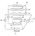
- the refrigeration cycle apparatus shown in FIG. 1 is a refrigeration cycle apparatus for a vehicle that is used to adjust in-vehicle equipment and a vehicle interior space (in other words, a space to be blown) to an appropriate temperature.
- the refrigeration cycle apparatus is applied to a hybrid vehicle that obtains driving force for vehicle travel from an engine (in other words, an internal combustion engine) and a travel electric motor.
- the hybrid vehicle of the present embodiment is configured as a plug-in hybrid vehicle capable of charging power supplied from an external power source (in other words, commercial power source) when the vehicle is stopped to a battery (in other words, an in-vehicle battery) mounted on the vehicle.
- a battery in other words, an in-vehicle battery mounted on the vehicle.
- the battery for example, a lithium ion battery can be used.
- the driving force output from the engine is used not only for driving the vehicle but also for operating the generator.
- the electric power generated by the generator and the electric power supplied from the external power source can be stored in the battery, and the electric power stored in the battery constitutes the refrigeration cycle apparatus as well as the electric motor for traveling. Supplied to various in-vehicle devices including electric components.
- the refrigeration cycle 10 is a vapor compression refrigerator that includes a compressor 11, a high-pressure side heat exchanger 12, a first expansion valve 13, an outdoor heat exchanger 14, a second expansion valve 15, and a low-pressure side heat exchanger 16.
- a chlorofluorocarbon refrigerant is used as the refrigerant, and a subcritical refrigeration cycle in which the high-pressure side refrigerant pressure does not exceed the critical pressure of the refrigerant is configured.
- the compressor 11 is an electric compressor driven by electric power supplied from a battery or a belt-driven compressor driven by a belt, and sucks, compresses and discharges the refrigerant of the refrigeration cycle 10.
- the high-pressure side heat exchanger 12 is a condenser that condenses the high-pressure side refrigerant by exchanging heat between the high-pressure side refrigerant discharged from the compressor 11 and the cooling water of the high-temperature cooling water circuit 20.
- the cooling water of the high-temperature cooling water circuit 20 is a fluid as a heat medium.
- the cooling water of the high temperature cooling water circuit 20 is a high temperature heat medium.
- the high temperature coolant circuit 20 is a heat medium circuit in which a high temperature heat medium circulates.
- a liquid containing at least ethylene glycol, dimethylpolysiloxane or nanofluid, or an antifreeze liquid is used as the cooling water of the high-temperature cooling water circuit 20.
- the 1st expansion valve 13 is the 1st decompression part which decompresses and expands the liquid phase refrigerant which flowed out from high pressure side heat exchanger 12.
- the first expansion valve 13 is an electric variable throttle mechanism, and includes a valve body and an electric actuator.
- the valve body is configured to be able to change the passage opening (in other words, the throttle opening) of the refrigerant passage.
- the electric actuator has a stepping motor that changes the throttle opening of the valve body.
- the first expansion valve 13 is composed of a variable throttle mechanism with a fully open function that fully opens the refrigerant passage when the throttle opening is fully opened. That is, the first expansion valve 13 can prevent the refrigerant from depressurizing by fully opening the refrigerant passage.
- the operation of the first expansion valve 13 is controlled by a control signal output from the control device 40 shown in FIG.
- the outdoor heat exchanger 14 is a refrigerant outdoor air heat exchanger that exchanges heat between the refrigerant flowing out of the first expansion valve 13 and the outside air. Outside air is blown to the outdoor heat exchanger 14 by an outdoor blower 17.
- the outdoor blower 17 is a blower that blows outside air toward the outdoor heat exchanger 14.
- the outdoor blower 17 is an electric blower that drives a fan with an electric motor.
- the outdoor blower 17 is a wind speed adjusting unit that adjusts the wind speed of the outside air flowing into the outdoor heat exchanger 14.
- the outdoor heat exchanger 14 and the outdoor blower 17 are disposed at the forefront of the vehicle. Accordingly, the traveling wind can be applied to the outdoor heat exchanger 14 when the vehicle is traveling.
- the outdoor heat exchanger 14 When the temperature of the refrigerant flowing through the outdoor heat exchanger 14 is lower than the temperature of the outside air, the outdoor heat exchanger 14 functions as a heat absorber that causes the refrigerant to absorb the heat of the outside air. When the temperature of the refrigerant flowing through the outdoor heat exchanger 14 is higher than the temperature of the outside air, the outdoor heat exchanger 14 functions as a radiator that radiates the heat of the refrigerant to the outside air.
- the second expansion valve 15 is a second decompression unit that decompresses and expands the liquid-phase refrigerant that has flowed out of the outdoor heat exchanger 14.
- the second expansion valve 15 is an electric variable throttle mechanism, and includes a valve body and an electric actuator.
- the valve body is configured to be able to change the passage opening (in other words, the throttle opening) of the refrigerant passage.
- the electric actuator has a stepping motor that changes the throttle opening of the valve body.
- the second expansion valve 15 is composed of a variable throttle mechanism with a fully open function that fully opens the refrigerant passage when the throttle opening is fully opened. That is, the second expansion valve 15 can prevent the refrigerant from depressurizing by fully opening the refrigerant passage.
- the operation of the second expansion valve 15 is controlled by a control signal output from the control device 40 shown in FIG.
- the heat absorption mode and the heat radiation mode are switched by changing the throttle opening of the first expansion valve 13 and the second expansion valve 15.
- the heat absorption mode is an operation mode in which the outdoor heat exchanger 14 absorbs heat from the outside air to the refrigerant.
- the heat dissipation mode is an operation mode in which the outdoor heat exchanger 14 radiates heat from the refrigerant to the outside air.
- the low-pressure side heat exchanger 16 is an evaporator that evaporates the low-pressure refrigerant by exchanging heat between the low-pressure refrigerant flowing out of the second expansion valve 15 and the cooling water of the low-temperature cooling water circuit 30.
- the gas-phase refrigerant evaporated in the low-pressure side heat exchanger 16 is sucked into the compressor 11 and compressed.
- the cooling water in the low-temperature cooling water circuit 30 is a fluid as a heat medium.
- the cooling water of the low-temperature cooling water circuit 30 is a low-temperature heat medium.
- the low-temperature cooling water circuit 30 is a heat medium circuit in which a low-temperature heat medium circulates.
- a liquid containing at least ethylene glycol, dimethylpolysiloxane or nanofluid, or an antifreeze liquid is used as the cooling water of the low-temperature cooling water circuit 30, a liquid containing at least ethylene glycol, dimethylpolysiloxane or nanofluid, or an antifreeze liquid is used as the cooling water of the low-temperature cooling water circuit 30, a liquid containing at least ethylene glycol, dimethylpolysiloxane or nanofluid, or an antifreeze liquid is used as the cooling water of the low-temperature cooling water circuit 30, a liquid containing at least ethylene glycol, dimethylpolysiloxane or nanofluid,
- a high-pressure side heat exchanger 12 In the high-temperature cooling water circuit 20, a high-pressure side heat exchanger 12, a high-temperature side pump 21, a heater core 22, an engine 23, and a flow rate adjusting valve 24 are arranged.
- the high temperature side pump 21 is a heat medium pump that sucks and discharges cooling water.
- the high temperature side pump 21 is an electric pump.
- the high temperature side pump 21 is a flow rate adjusting unit that adjusts the flow rate of the cooling water circulating in the high temperature cooling water circuit 20.
- the heater core 22 heat-exchanges the cooling water of the high-temperature cooling water circuit 20 and the air blown into the vehicle interior (in other words, the air blow target space) to heat the air blown into the vehicle interior. It is.
- the cooling water radiates heat to the air blown into the vehicle interior due to a change in sensible heat. That is, in the heater core 22, even if the cooling water dissipates heat to the air blown into the passenger compartment, the cooling water remains in a liquid phase and does not change phase.
- the engine 23 is a temperature control target device whose temperature is adjusted by the cooling water of the high-temperature cooling water circuit 20.
- the heater core 22 and the engine 23 are arranged in parallel with each other in the flow of the cooling water.
- the flow rate adjustment valve 24 is a flow rate ratio adjusting unit that adjusts the flow rate ratio between the cooling water flowing through the heater core 22 and the cooling water flowing through the engine 23.
- the flow rate adjusting valve 24 is a supply rate adjusting unit that adjusts the rate of supply of heat of the high-pressure side refrigerant of the refrigeration cycle 10 by adjusting the flow rate rate of the cooling water with respect to the engine 23 and the heater core 22.
- the high temperature side pump 21 and the flow rate adjustment valve 24 are high pressure side flow rate adjustment units that adjust the flow rate of the cooling water flowing through the high pressure side heat exchanger 12.
- the high temperature side pump 21 and the flow rate adjustment valve 24 are temperature control flow rate adjustment units that adjust the flow rate of the cooling water flowing through the engine 23.
- the high temperature side pump 21 and the flow rate adjusting valve 24 are heat exchange amount adjusting units that adjust the heat exchange amount in the heater core 22 by adjusting the flow rate of the cooling water flowing through the heater core 22.
- the low temperature side pump 31 is a heat medium pump that sucks and discharges cooling water.
- the low temperature side pump 31 is an electric pump.
- the low temperature side pump 31 is a low temperature side flow rate adjusting unit that adjusts the flow rate of the cooling water circulating in the low temperature cooling water circuit 30.
- the cooler core 32 is a low-temperature heat medium heat exchanger that cools the air blown into the vehicle interior by exchanging heat between the cooling water of the low-temperature coolant circuit 30 and the air blown into the vehicle interior. Therefore, the low-pressure side heat exchanger 16 causes the low-pressure side refrigerant of the refrigeration cycle 10 to indirectly absorb heat from the air blown into the vehicle interior.
- the cooling water absorbs heat from the air blown into the vehicle interior due to the sensible heat change. That is, in the cooler core 32, even if the cooling water absorbs heat from the air blown into the passenger compartment, the cooling water remains in a liquid phase and does not change phase.
- the cooler core 32 and the heater core 22 are accommodated in an air conditioning casing (not shown).
- the air conditioning casing is an air passage forming member that forms an air passage.
- the air-conditioning casing is disposed inside an instrument panel (not shown) located in the foremost part of the vehicle interior.
- the heater core 22 is disposed downstream of the cooler core 32 in the air passage in the air conditioning casing.
- an inside / outside air switching box and an indoor blower 33 are arranged in the air conditioning casing.
- the inside / outside air switching box is an inside / outside air switching unit that switches between introduction of inside air and outside air into an air passage in the air conditioning casing.
- the indoor blower 33 sucks and blows in the inside air and outside air introduced into the air passage in the air conditioning casing by the inside / outside air switching box.
- An air mix door (not shown) is arranged between the cooler core 32 and the heater core 22 in the air passage in the air conditioning casing.
- the air mix door is an air volume ratio adjusting unit that adjusts an air volume ratio between cold air flowing into the heater core 22 out of the cold air passing through the cooler core 32 and cold air flowing bypassing the heater core 22.
- the operation of the air mix door is controlled by the control device 40.
- the air-conditioning casing has an air outlet (not shown).
- the conditioned air adjusted to a desired temperature by the air mix door is blown out into the passenger compartment through the blowout port.
- the control device 40 is composed of a well-known microcomputer including a CPU, a ROM, a RAM and the like and its peripheral circuits.
- the control device 40 performs various calculations and processes based on a control program stored in the ROM.
- Various devices to be controlled are connected to the output side of the control device 40.
- the control device 40 is a control unit that controls operations of various devices to be controlled.
- the control target devices controlled by the control device 40 are the compressor 11, the first expansion valve 13, the second expansion valve 15, the outdoor blower 17, the high temperature side pump 21, the low temperature side pump 31, the indoor blower 33, and the like.
- Software and hardware for controlling the electric motor of the compressor 11 in the control device 40 are a refrigerant discharge capacity control unit that controls the refrigerant discharge capacity of the compressor 11.
- Software and hardware for controlling the first expansion valve 13 in the control device 40 is a first throttle control unit that controls the throttle opening of the first expansion valve 13.
- Software and hardware for controlling the second expansion valve 15 in the control device 40 is a second throttle control unit that controls the throttle opening of the second expansion valve 15.
- Software and hardware for controlling the outdoor blower 17 in the control device 40 are an outside air blowing capacity control unit that controls the outside blowing capacity of the outdoor blower 17.
- Software and hardware for controlling the high temperature side pump 21 in the control device 40 are a high temperature side heat medium flow control unit for controlling the flow rate of the high temperature side heat medium.
- Software and hardware for controlling the low temperature side pump 31 in the control device 40 is a low temperature side heat medium flow control unit for controlling the flow rate of the low temperature side heat medium.
- Software and hardware for controlling the indoor blower 33 in the control device 40 is an indoor blower control unit.
- control device 40 On the input side of the control device 40, various air conditioning such as an inside air temperature sensor 41, an outside air temperature sensor 42, a solar radiation amount sensor 43, an outdoor heat exchanger temperature sensor 44, a low pressure side heat exchanger temperature sensor 45, an engine temperature sensor 46, and the like.
- a sensor group for control is connected.
- the inside air temperature sensor 41 is an inside air temperature detecting unit that detects the inside air temperature Tr (that is, the vehicle interior temperature).
- the outside air temperature sensor 42 is an outside air temperature detector that detects the outside air temperature Tam.
- the solar radiation amount sensor 43 is a solar radiation amount detector that detects the solar radiation amount Ts in the vehicle interior.
- the outdoor heat exchanger temperature sensor 44 is an outdoor heat exchanger temperature detection unit that detects the temperature of the outdoor heat exchanger 14. For example, the outdoor heat exchanger temperature sensor 44 detects the temperature of the refrigerant flowing into the outdoor heat exchanger 14.
- the low-pressure side heat exchanger temperature sensor 45 detects the temperature of the cooling water flowing out from the low-pressure side heat exchanger 16.
- the engine temperature sensor 46 is an engine temperature detection unit that detects the temperature of the engine 23. For example, the engine temperature sensor 46 detects the temperature of the refrigerant flowing into the engine 23.
- An operation panel 48 is connected to the input side of the control device 40.
- the operation panel 48 is disposed in the vicinity of the instrument panel in the front part of the vehicle interior and is operated by a passenger.
- Various operation switches are provided on the operation panel 48. Operation signals from various operation switches are input to the control device 40.
- the various operation switches of the operation panel 48 are an air conditioner switch 48a, a temperature setting switch, and the like.
- the air conditioner switch 48a sets the operation / stop of the air conditioning (that is, the operation / stop of the compressor 11).
- the air conditioner switch 48a is a cooling request operation unit for requesting that the air blown into the vehicle interior is cooled using the low-pressure side heat exchanger 16.
- the temperature setting switch is a temperature setting operation unit for setting the set temperature in the passenger compartment.
- the control device 40 determines the operation mode of the refrigeration cycle device for a vehicle when the compressor 11 is operating due to the air conditioner switch 48a of the operation panel 48 being turned on.
- the control device 40 determines the operation mode of the vehicular refrigeration cycle apparatus based on whether or not the engine 23 needs to be warmed up, the target blowing temperature TAO, and the like.
- Whether the engine 23 needs to be warmed up is determined based on the temperature detected by the engine temperature sensor 46, that is, the temperature of the engine 23. For example, when the temperature of the engine 23 is lower than a predetermined temperature, it is determined that the engine 23 needs to be warmed up.
- the target air temperature TAO is the target temperature of the air that is blown out into the passenger compartment.
- the control device 40 calculates the target blowing temperature TAO based on the following mathematical formula.
- TAO Kset ⁇ Tset ⁇ Kr ⁇ Tr ⁇ Kam ⁇ Tam ⁇ Ks ⁇ Ts + C
- Tset is the vehicle interior set temperature set by the temperature setting switch of the operation panel 48
- Tr is the inside air temperature detected by the inside air temperature sensor 41
- Tam is the outside air temperature detected by the outside air temperature sensor 42
- Ts is This is the amount of solar radiation detected by the solar radiation amount sensor 43.
- Kset, Kr, Kam, Ks are control gains
- C is a correction constant.
- the control device 40 does not need to warm up the engine 23, and executes the cooling mode when the target blowing temperature TAO is lower than the inside air temperature Tr.
- the cooling mode is a heat release mode in which the high-pressure side refrigerant of the refrigeration cycle 10 radiates heat to the outside air in the outdoor heat exchanger 14.
- the control device 40 sets the first expansion valve 13 to a fully open state and the second expansion valve 15 to a throttle state. In the cooling mode, the control device 40 stops the high temperature side pump 21 and drives the low temperature side pump 31.
- the control device 40 determines the degree of supercooling of the refrigerant flowing into the compressor 11 so that the degree of supercooling of the refrigerant flowing into the second expansion valve 15 approaches a predetermined target supercooling degree or the degree of superheating of the refrigerant flowing into the compressor 11 is predetermined.
- the throttle opening degree of the second expansion valve 15 is determined so as to approach the target superheat degree.
- the target supercooling degree and the target superheat degree are determined such that the coefficient of performance (so-called COP) of the cycle approaches the maximum value.
- the high-pressure refrigerant discharged from the compressor 11 flows into the high-pressure side heat exchanger 12.
- the cooling water of the high temperature cooling water circuit 20 does not circulate in the high pressure side heat exchanger 12. Therefore, the refrigerant that has flowed into the high-pressure side heat exchanger 12 flows out of the high-pressure side heat exchanger 12 with little heat exchange with the cooling water in the high-temperature cooling water circuit 20.
- the refrigerant that has flowed out of the high-pressure side heat exchanger 12 flows into the first expansion valve 13. At this time, since the first expansion valve 13 fully opens the refrigerant passage, the refrigerant flowing out from the high pressure side heat exchanger 12 flows into the outdoor heat exchanger 14 without being depressurized by the first expansion valve 13. To do.
- the refrigerant flowing into the outdoor heat exchanger 14 radiates heat to the outside air blown by the outdoor blower 17 in the outdoor heat exchanger 14.
- the refrigerant that has flowed out of the outdoor heat exchanger 14 flows into the second expansion valve 15 and is decompressed and expanded at the second expansion valve 15 until it becomes a low-pressure refrigerant.
- the low-pressure refrigerant decompressed by the second expansion valve 15 flows into the low-pressure side heat exchanger 16, absorbs heat from the cooling water in the low-temperature cooling water circuit 30, and evaporates. Thereby, since the cooling water of the low-temperature cooling water circuit 30 is cooled, the air blown by the indoor blower 33 in the cooler core 32 is cooled.
- the refrigerant flowing out from the low-pressure side heat exchanger 16 flows to the suction side of the compressor 11 and is compressed again by the compressor 11.
- the air cooled by the cooler core 32 can be blown out into the passenger compartment. Thereby, cooling of a vehicle interior is realizable.
- the control device 40 does not need to warm up the engine 23, and executes the heating mode when the target blowing temperature TAO is higher than the inside air temperature Tr.
- the heating mode is an endothermic mode in which the low-pressure side refrigerant of the refrigeration cycle 10 absorbs heat from outside air in the outdoor heat exchanger 14.
- the control device 40 brings the first expansion valve 13 into a throttled state and the second expansion valve 15 into a fully open state. In the heating mode, the control device 40 drives the high temperature side pump 21 and stops the low temperature side pump 31.
- the control device 40 has a predetermined degree of superheat of the refrigerant flowing into the compressor 11 so that the degree of supercooling of the refrigerant flowing into the first expansion valve 13 approaches a predetermined target subcooling degree.
- the throttle opening degree of the first expansion valve 13 is determined so as to approach the target degree of superheat.
- the control device 40 determines the operating state of the air mix door so that the air mix door fully opens the air passage of the heater core 22 and the entire flow rate of the blown air that has passed through the cooler core 32 passes through the air passage of the heater core 22.
- the high-pressure refrigerant discharged from the compressor 11 flows into the high-pressure side heat exchanger 12, exchanges heat with the cooling water in the high-temperature cooling water circuit 20, and dissipates heat. Thereby, the cooling water of the high temperature cooling water circuit 20 is heated.
- the refrigerant that has flowed out of the high-pressure side heat exchanger 12 flows into the first expansion valve 13 and is decompressed until it becomes a low-pressure refrigerant.
- the low-pressure refrigerant decompressed by the first expansion valve 13 flows into the outdoor heat exchanger 14, absorbs heat from the outside air blown by the outdoor blower 17, and evaporates.
- the refrigerant that has flowed out of the outdoor heat exchanger 14 flows into the second expansion valve 15. At this time, since the second expansion valve 15 is fully opened, the refrigerant flowing out of the outdoor heat exchanger 14 flows into the low-pressure side heat exchanger 16 without being depressurized by the second expansion valve 15.
- the cooling water of the low temperature cooling water circuit 30 does not circulate in the low pressure side heat exchanger 16. Therefore, the low-pressure refrigerant flowing into the low-pressure side heat exchanger 16 hardly absorbs heat from the cooling water in the low-temperature cooling water circuit 30. Then, the refrigerant flowing out from the low-pressure side heat exchanger 16 flows to the suction side of the compressor 11 and is compressed again by the compressor 11.
- the heat of the high-pressure refrigerant discharged from the compressor 11 by the high-pressure side heat exchanger 12 is radiated to the cooling water of the high-temperature cooling water circuit 20, and the high-temperature cooling water circuit 20 is heated by the heater core 22.
- the heat of the cooling water can be dissipated to the air blown into the vehicle interior, and the heated air can be blown out into the vehicle interior. Thereby, heating of a vehicle interior is realizable.
- the control device 40 executes the cooling warm-up mode when the engine 23 needs to be warmed up and the target blowing temperature TAO is lower than the inside air temperature Tr.
- the cooling warm-up mode is an endothermic mode in which the low-pressure side refrigerant of the refrigeration cycle 10 absorbs heat from outside air in the outdoor heat exchanger 14.
- the control device 40 In the cooling / warming-up mode, the control device 40 causes the first expansion valve 13 to be in the throttle state and causes the second expansion valve 15 to be in the fully open state. In the cooling warm-up mode, the control device 40 drives the high temperature side pump 21 and the low temperature side pump 31.
- the control device 40 determines the throttle opening degree of the first expansion valve 13 so that the supercooling degree of the refrigerant flowing into the first expansion valve 13 approaches a predetermined target supercooling degree.
- the control device 40 determines the operating state of the flow rate adjustment valve 24 so that the cooling water flows through the engine 23.
- the high-pressure refrigerant discharged from the compressor 11 flows into the high-pressure side heat exchanger 12, exchanges heat with the cooling water in the high-temperature cooling water circuit 20, and dissipates heat. Thereby, the cooling water of the high temperature cooling water circuit 20 is heated.
- the refrigerant that has flowed out of the high-pressure side heat exchanger 12 flows into the first expansion valve 13 and is decompressed until it becomes a low-pressure refrigerant.
- the low-pressure refrigerant decompressed by the first expansion valve 13 flows into the outdoor heat exchanger 14, absorbs heat from the outside air blown by the outdoor blower 17, and evaporates.
- the refrigerant that has flowed out of the outdoor heat exchanger 14 flows into the second expansion valve 15.
- the refrigerant flowing out of the outdoor heat exchanger 14 flows into the low-pressure side heat exchanger 16 without being depressurized by the second expansion valve 15, It absorbs heat from the cooling water of the cooling water circuit 30 and evaporates.
- the refrigerant absorbs heat in both the outdoor heat exchanger 14 and the low-pressure heat exchanger 16 and evaporates.
- the air cooled by the cooler core 32 can be blown out into the passenger compartment. Thereby, cooling of a vehicle interior is realizable.
- the heat of the high-pressure refrigerant discharged from the compressor 11 by the high-pressure side heat exchanger 12 is radiated to the cooling water of the high-temperature cooling water circuit 20, and the cooling water of the high-temperature cooling water circuit 20 is discharged.
- the control device 40 executes the heating warm-up mode when it is necessary to warm up the engine 23 and the target blowing temperature TAO is higher than the inside air temperature Tr.
- the heating warm-up mode is an endothermic mode in which the low-pressure side refrigerant of the refrigeration cycle 10 absorbs heat from the outside air in the outdoor heat exchanger 14.
- the control device 40 In the heating / warming-up mode, the control device 40 causes the first expansion valve 13 to be in a throttled state and causes the second expansion valve 15 to be in a fully open state. In the heating mode, the control device 40 drives the high temperature side pump 21 and stops the low temperature side pump 31.
- the control device 40 determines the throttle opening degree of the first expansion valve 13 so that the supercooling degree of the refrigerant flowing into the first expansion valve 13 approaches a predetermined target supercooling degree.
- the control device 40 determines the operating state of the flow rate adjustment valve 24 so that the cooling water flows through the heater core 22 and the engine 23.
- the control device 40 determines the operating state of the air mix door so that the air mix door fully opens the air passage of the heater core 22 and the entire flow rate of the blown air that has passed through the cooler core 32 passes through the air passage of the heater core 22.
- the high-pressure refrigerant discharged from the compressor 11 flows into the high-pressure side heat exchanger 12, exchanges heat with the cooling water in the high-temperature cooling water circuit 20, and dissipates heat. Thereby, the cooling water of the high temperature cooling water circuit 20 is heated.
- the refrigerant that has flowed out of the high-pressure side heat exchanger 12 flows into the first expansion valve 13 and is decompressed until it becomes a low-pressure refrigerant.
- the low-pressure refrigerant decompressed by the first expansion valve 13 flows into the outdoor heat exchanger 14, absorbs heat from the outside air blown by the outdoor blower 17, and evaporates.
- the refrigerant that has flowed out of the outdoor heat exchanger 14 flows into the second expansion valve 15. At this time, since the second expansion valve 15 is fully opened, the refrigerant flowing out of the outdoor heat exchanger 14 flows into the low-pressure side heat exchanger 16 without being depressurized by the second expansion valve 15.
- the cooling water of the low temperature cooling water circuit 30 does not circulate in the low pressure side heat exchanger 16. Therefore, the low-pressure refrigerant flowing into the low-pressure side heat exchanger 16 hardly absorbs heat from the cooling water in the low-temperature cooling water circuit 30. Then, the refrigerant flowing out from the low-pressure side heat exchanger 16 flows to the suction side of the compressor 11 and is compressed again by the compressor 11.
- the heat of the high-pressure refrigerant discharged from the compressor 11 by the high-pressure side heat exchanger 12 is dissipated to the cooling water of the high-temperature cooling water circuit 20, and the high-temperature cooling water is obtained by the heater core 22.
- the heat of the cooling water of the circuit 20 can be dissipated to the air blown into the vehicle interior, and the heated air can be blown out into the vehicle interior. Thereby, heating of a vehicle interior is realizable.
- the heat of the cooling water in the high-temperature cooling water circuit 20 can be radiated to the engine 23. Thereby, warming-up of the engine 23 is realizable.
- the pressure of the outdoor heat exchanger 14 is increased by reducing the throttle opening (in other words, the passage area) of the second expansion valve 15, and the temperature with the outside air Since the difference is reduced, the heat absorption amount of the outdoor heat exchanger 14 is reduced.
- the pressure of the outdoor heat exchanger 14 is increased by increasing the throttle opening degree (in other words, the passage area) of the first expansion valve 13, and the temperature with the outside air. Since the difference is reduced, the heat absorption amount of the outdoor heat exchanger 14 is reduced.
- the outdoor heat exchanger 14 In the heating mode, the cooling warm-up mode, and the heating warm-up mode, since the wind speed of the outdoor air flowing through the outdoor heat exchanger 14 is decreased by reducing the driving power (in other words, the rotational speed) of the outdoor blower 17, the outdoor heat The heat absorption amount of the exchanger 14 is reduced.
- the first expansion valve 13, the second expansion valve 15, and the outdoor blower 17 are heat exchange amount adjusting units that adjust the heat exchange amount in the outdoor heat exchanger 14.
- the first expansion valve 13, the second expansion valve 15, and the outdoor blower 17 are endothermic amount adjusting units that adjust the amount of heat absorbed by the low-pressure refrigerant from the outside air in the outdoor heat exchanger 14 in the endothermic mode. is there.
- the endothermic mode is an operation mode in which the low-pressure side refrigerant of the refrigeration cycle 10 absorbs heat from the outside air in the outdoor heat exchanger 14.
- the control device 40 is required to cool the air blown into the vehicle interior.
- the operation of the first expansion valve 13 and the second expansion valve 15 is controlled so as to enter the heat absorption mode.
- both the outdoor heat exchanger 14 and the low pressure side heat exchanger 16 can absorb the heat to the low pressure side refrigerant of the refrigeration cycle 10. it can.
- the air blown into the vehicle interior can be cooled, and the ability to warm up the engine 23 can be increased compared to the case where the outdoor heat exchanger 14 radiates heat from the refrigerant to the outside air. Air cooling and warm-up of the engine 23 can both be achieved.
- control device 40 reduces the amount of heat absorbed by the low-pressure refrigerant from the outside air in the outdoor heat exchanger 14 as time elapses after the first expansion valve 13 and the second expansion valve 15 are switched to the heat absorption mode.
- the operation of at least one of the first expansion valve 13, the second expansion valve 15, and the outdoor blower 17 is controlled so as to be.
- the amount of heat supplied to the engine 23 decreases, so that the engine 23 can be prevented from being warmed up excessively.
- the control device 40 switches the first expansion valve 13 and the second expansion valve 15 to switch to the heat dissipation mode when a predetermined time has elapsed.
- Control the operation of The heat release mode is an operation mode in which the high-pressure side refrigerant of the refrigeration cycle 10 radiates heat to the outside air in the outdoor heat exchanger 14.
- the amount of heat necessary for warming up the engine 23 decreases, the amount of heat absorbed by the low-pressure side heat exchanger 16 can be increased, and the cooling capacity of the air blown into the vehicle interior can be increased.
- the controller 40 supplies the high-pressure side refrigerant heat supply rate to the heater core 22 (specifically, the heater core as time elapses after the first expansion valve 13 and the second expansion valve 15 are switched to the heat absorption mode.
- the operation of the flow rate adjusting valve 24 is controlled so that the ratio of the cooling water to 22) increases.
- the control device 40 increases the heat exchange amount in the heater core 22 (specifically, cooling water flowing through the heater core 22 as time elapses).
- the operation of the flow rate adjusting valve 24 is controlled so that the flow rate) increases.
- the heating capacity of the air blown into the passenger compartment can be increased.
- control device 40 determines that the high-pressure side heat exchanger 12, the outdoor heat exchanger 14, the low-pressure side heat exchanger as time elapses after the first expansion valve 13 and the second expansion valve 15 are switched to the heat absorption mode.
- the operation of at least one of the high temperature side pump 21 and the flow rate adjusting valve 24 is controlled so that the order of the absolute heat exchange amount of the heater core 22 in the comparison of the absolute heat exchange amount of the heater core 22 and the heater core 22 is increased.
- the order of the absolute amount of heat exchange refers to the order from the one with the largest absolute amount of heat exchange.
- the heating capacity of the air blown into the passenger compartment can be increased.
- control device 40 determines that the high-pressure side heat exchanger 12, the outdoor heat exchanger 14, the low-pressure side heat exchanger as time elapses after the first expansion valve 13 and the second expansion valve 15 are switched to the heat absorption mode.
- the operation of at least one of the first expansion valve 13, the second expansion valve 15, and the outdoor blower 17 is performed so that the order of the absolute heat exchange amount of the outdoor heat exchanger 14 in the comparison of the absolute heat exchange amount between the heater core 22 and the heater core 22 decreases.
- the order of the absolute amount of heat exchange refers to the order from the one with the largest absolute amount of heat exchange.
- control device 40 determines that the high-pressure side heat exchanger 12, the outdoor heat exchanger 14, the low-pressure side heat exchanger as time elapses after the first expansion valve 13 and the second expansion valve 15 are switched to the heat absorption mode. 16 and the heater core 22 are compared with each other, and the operation of the low temperature side pump 31 is controlled so that the order of the absolute heat exchange amount of the low pressure side heat exchanger 16 is increased.
- the dehumidifying ability of the low-pressure side heat exchanger 16 can be increased as the amount of moisture in the vehicle interior increases due to the breathing and sweating of the occupant, so that an increase in the humidity in the vehicle interior can be suppressed.
- control device 40 controls the refrigerant discharge capacity of the compressor 11 according to the heat exchange amount required by the low pressure side heat exchanger 16. Specifically, the control device 40 controls the refrigerant discharge capacity of the compressor 11 so that the temperature of the low-pressure side heat exchanger 16 approaches the target temperature of the low-pressure side heat exchanger 16.
- the control device 40 determines that the heat exchange amount of the low pressure side heat exchanger 16 is greater than the heat exchange amount required by the low pressure side heat exchanger 16 even if the refrigerant discharge capacity of the compressor 11 is maximum.
- the operation of at least one of the first expansion valve 13, the second expansion valve 15, and the outdoor blower 17 is controlled so that the heat absorption amount of the outdoor heat exchanger 14 is reduced.
- the case where it is determined that the heat exchange amount of the low pressure side heat exchanger 16 is less than the heat exchange amount required by the low pressure side heat exchanger 16 is, for example, that the temperature of the low pressure side heat exchanger 16 is low pressure side heat exchange This is a case where the target temperature of the vessel 16 is not approached.
- the heat exchange amount of the low pressure side heat exchanger 16 can be further increased, so that the heat exchange amount of the low pressure side heat exchanger is required. Insufficient heat exchange can be suppressed.
- the control device 40 determines that the heat exchange amount of the low pressure side heat exchanger 16 is greater than the heat exchange amount required by the low pressure side heat exchanger 16 even if the refrigerant discharge capacity of the compressor 11 is maximum.
- the operations of the first expansion valve 13 and the second expansion valve 15 are controlled so as to switch to the heat dissipation mode.
- the heat exchange amount of the low pressure side heat exchanger 16 can be further increased, so that the heat exchange amount of the low pressure side heat exchanger is required. Insufficient heat exchange can be suppressed.
- control device 40 controls the high temperature side pump 21 and the flow rate adjustment valve 24 so that the flow rate of the cooling water flowing through the high pressure side heat exchanger 12 decreases as the temperature of the cooling water flowing into the high pressure side heat exchanger 12 increases. Control at least one of the operations.
- control device 40 controls the operation of at least one of the high temperature side pump 21 and the flow rate adjusting valve 24 so that the flow rate of the cooling water flowing through the engine 23 increases as the temperature of the engine 23 increases.
- the flow rate of the cooling water flowing through the engine 23 is decreased to increase the temperature rise amount of the engine 23, and the flow rate of the cooling water flowing through the engine 23 is increased as the temperature of the engine 23 increases.
- the amount of temperature increase of the engine 23 can be reduced by increasing the number.
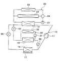
- the low-pressure side heat exchanger 16 and the cooler core 32 exchange heat between the low-pressure refrigerant and the air blown into the vehicle interior.
- the present embodiment as shown in FIG. Heat exchange between the low-pressure refrigerant and the air blown into the passenger compartment.
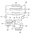
- the low-pressure side heat exchanger 16 causes the low-pressure side refrigerant of the refrigeration cycle 10 to indirectly absorb heat from the air blown into the vehicle interior, but in this embodiment, the low-pressure side heat exchanger 50. causes the low-pressure side refrigerant of the refrigeration cycle 10 to directly absorb heat from the air blown into the passenger compartment.
- the low-pressure side heat exchanger 50 is an evaporator that evaporates the low-pressure refrigerant by exchanging heat between the low-pressure refrigerant flowing out of the second expansion valve 15 and the air blown into the passenger compartment.
- the low-pressure side heat exchanger 50 is a low-temperature-side heat medium heat exchanger that cools air that is blown into the vehicle interior by exchanging heat between the low-pressure refrigerant that has flowed out of the second expansion valve 15 and the air that is blown into the vehicle interior. is there.
- the refrigeration cycle 10 includes a bypass unit 51 and a bypass flow rate adjustment valve 52.
- the bypass part 51 forms a refrigerant channel through which the refrigerant flows by bypassing the outdoor heat exchanger 14.
- the bypass flow rate adjustment valve 52 is an opening degree adjustment valve that adjusts the opening degree of the flow path of the bypass unit 51.
- the bypass flow rate adjustment valve 52 adjusts the flow rate of the refrigerant flowing through the outdoor heat exchanger 14 by adjusting the flow rate of the refrigerant flowing through the bypass unit 51.
- the bypass flow rate adjustment valve 52 is a bypass adjustment unit that adjusts the flow rate ratio of the high-pressure side refrigerant or the low-pressure side refrigerant with respect to the outdoor heat exchanger 14 and the bypass unit 51.
- the operation of the bypass flow rate adjustment valve 52 is controlled by the control device 40.
- the bypass flow rate adjustment valve 52 is a heat exchange amount adjusting unit that adjusts the heat exchange amount in the outdoor heat exchanger 14.
- the bypass flow rate adjustment valve 52 is an endothermic amount adjusting unit that adjusts the amount of heat absorbed by the low-pressure side refrigerant from the outside air in the outdoor heat exchanger 14 in the endothermic mode.
- the heat exchange amount of the outdoor heat exchanger 14 can be adjusted as in the above embodiment.
- the flow rate adjustment valve 24 adjusts the flow rate ratio between the cooling water flowing through the heater core 22 and the cooling water flowing through the engine 23.
- the flow rate ratio between the cooling water flowing through the heater core 22 and the cooling water flowing through the engine 23 is adjusted.
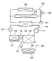
- the heater core side shut-off valve 53 is an open / close valve that opens and closes the cooling water flow path on the heater core 22 side in the high-temperature cooling water circuit 20.
- the heater core side shut-off valve 53 is a supply rate adjustment unit that adjusts the heat supply rate of the high-pressure side refrigerant of the refrigeration cycle 10 with respect to the engine 23 and the heater core 22.
- the heater core side shut-off valve 53 is a heat exchange amount adjusting unit that adjusts the heat exchange amount in the heater core 22.
- the operation of the heater core side shutoff valve 53 is controlled by a control signal output from the control device 40.
- the heater core side shut-off valve 53 closes the cooling water flow path on the heater core 22 side in the high temperature cooling water circuit 20 when the engine 23 is warmed up. Thereby, the flow of the cooling water to the heater core 22 is interrupted, and the entire amount of the cooling water discharged from the high temperature side pump 21 flows through the engine 23. Therefore, the warm function capability of the engine 23 can be improved.
- the high temperature cooling water circuit 20 has the heater core side shut-off valve 53 that opens and closes the cooling water flow path on the heater core 22 side.
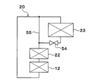
- the water circuit 20 has an engine side shut-off valve 54 that opens and closes a cooling water flow path on the engine 23 side.
- the engine 23 is arranged in series with the heater core 22 in the coolant flow of the high-temperature coolant circuit 20.
- the high-temperature coolant circuit 20 has an engine bypass unit 55.
- the engine bypass unit 55 forms a cooling water flow path in which cooling water flows by bypassing the engine 23.
- the engine side shut-off valve 54 is an open / close valve that opens and closes the coolant flow path on the engine 23 side in the high-temperature coolant circuit 20.
- the engine side shut-off valve 54 is a temperature control flow rate adjusting unit that adjusts the flow rate of the cooling water flowing through the engine 23.
- the engine-side shut-off valve 54 is a supply rate adjusting unit that adjusts the heat supply rate of the high-pressure side refrigerant of the refrigeration cycle 10 with respect to the engine 23 and the heater core 22.
- the operation of the engine side shut-off valve 54 is controlled by the control device 40.
- the engine-side shut-off valve 54 reduces the opening of the engine bypass unit 55, so that the flow rate of the cooling water flowing through the engine 23 decreases. Therefore, the flow rate of the cooling water flowing through the engine 23 can be adjusted.
- the refrigeration cycle 10 includes a first expansion valve 56 and a second expansion valve 57.
- the first expansion valve 56 is a first decompression unit that decompresses and expands the liquid-phase refrigerant that flows out from the high-pressure side heat exchanger 12 and into the outdoor heat exchanger 14.
- the second expansion valve 57 is a second decompression unit that decompresses and expands the liquid-phase refrigerant that flows out from the high-pressure side heat exchanger 12 and into the low-pressure side heat exchanger 16.
- the liquid-phase refrigerant that has flowed out of the high-pressure heat exchanger 12 branches and flows to the first expansion valve 56 side and the second expansion valve 57 side.
- the refrigerant decompressed by the first expansion valve 56 flows into the outdoor heat exchanger 14.
- the refrigerant decompressed by the second expansion valve 57 flows into the low-pressure side heat exchanger 16.
- the gas-phase refrigerant evaporated in the outdoor heat exchanger 14 and the gas-phase refrigerant evaporated in the low-pressure side heat exchanger 16 merge with each other and are sucked into the compressor 11.
- the first expansion valve 56 and the second expansion valve 57 are electric variable throttle mechanisms. The operation of the first expansion valve 56 and the second expansion valve 57 is controlled by the control device 40.
- the control device 40 controls the throttle opening degree of at least one of the first expansion valve 56 and the second expansion valve 57, so that the refrigerant flowing through the outdoor heat exchanger 14 and the refrigerant flowing through the low-pressure side heat exchanger 16 are reduced. Adjust the flow rate. Thereby, in the outdoor heat exchanger 14, the amount of heat absorbed by the low-pressure side refrigerant from the outside air can be adjusted.
- the refrigeration cycle 10 may include a third expansion valve 58 that decompresses and expands the gas-phase refrigerant evaporated in the low-pressure side heat exchanger 16.
- the third expansion valve 58 is an electric variable throttle mechanism. The operation of the third expansion valve 58 is controlled by the control device 40.
- the gas-phase refrigerant evaporated in the outdoor heat exchanger 14 and the gas-phase refrigerant decompressed and expanded in the third expansion valve 58 merge with each other and are sucked into the compressor 11.
- the refrigerant pressure of the low-pressure side heat exchanger 16 can be made higher than the refrigerant pressure of the outdoor heat exchanger 14. Therefore, it is possible to suppress the occurrence of frost in the cooler core 32 due to the cooling water temperature of the low-temperature cooling water circuit 30 being lowered to 0 ° C. or lower when the outside air temperature is 0 ° C. or lower.
- a shutter may be disposed in the vicinity of the outdoor heat exchanger 14.
- the shutter is driven to open and close by an electric actuator.
- the operation of the electric actuator is controlled by the control device 40.
- the shutter adjusts the opening degree of the outside air passage that flows through the outdoor heat exchanger 14. That is, the shutter is a heat exchange amount adjusting unit that adjusts the heat exchange amount in the outdoor heat exchanger 14 by adjusting the flow rate of the outside air flowing through the outdoor heat exchanger 14. Specifically, the shutter is an endothermic amount adjusting unit that adjusts the amount of heat absorbed by the low-pressure side refrigerant from the outside air in the outdoor heat exchanger 14 in the endothermic mode.
- the opening of the shutter 41 by reducing the opening of the shutter 41, the flow rate of the outside air flowing through the outdoor heat exchanger 14 can be reduced. Thereby, the amount of heat exchange in the outdoor heat exchanger 14 can be reduced.
- a pump for the heater core 22 and a pump for the engine 23 may be provided in the high-temperature coolant circuit 20, a pump for the heater core 22 and a pump for the engine 23 may be provided.
- the pump for the heater core 22 and the pump for the engine 23 are supply rate adjustment units that adjust the supply rate of heat of the high-pressure side refrigerant of the refrigeration cycle 10 to the engine 23 and the heater core 22.
- control device 40 independently controls the rotation speed of the pump for the heater core 22 and the rotation speed of the pump for the engine 23, whereby the flow rate ratio between the cooling water flowing through the heater core 22 and the cooling water flowing through the engine 23. Can be adjusted.
- the engine 23 is disposed as the temperature adjustment target device in the high-temperature cooling water circuit 20, but as the temperature control target device, a device that cannot function unless it reaches a predetermined temperature (for example, An EGR cooler) or a device whose performance increases as the temperature increases (for example, a lithium ion battery) may be disposed.
- a predetermined temperature for example, An EGR cooler
- a device whose performance increases as the temperature increases for example, a lithium ion battery
- cooling water is used as a heat medium for adjusting the temperature of the temperature control target device, but various media such as oil may be used as the heat medium.
- Nanofluid may be used as the heat medium.
- a nanofluid is a fluid in which nanoparticles having a particle size of the order of nanometers are mixed.
- the effect of improving the thermal conductivity in a specific temperature range the effect of increasing the heat capacity of the heat medium, the effect of preventing the corrosion of metal pipes and the deterioration of rubber pipes, and the heat medium at an extremely low temperature
- liquidity of can be acquired.
- Such an effect varies depending on the particle configuration, particle shape, blending ratio, and additional substance of the nanoparticles.
- the thermal conductivity can be improved, it is possible to obtain the same cooling efficiency even with a small amount of heat medium as compared with the cooling water using ethylene glycol.
- the amount of cold storage heat due to the sensible heat of the heat medium itself can be increased.
- the aspect ratio of the nanoparticles is preferably 50 or more. This is because sufficient thermal conductivity can be obtained.
- the aspect ratio is a shape index that represents the ratio of the vertical and horizontal dimensions of the nanoparticles.
- Nanoparticles containing any of Au, Ag, Cu and C can be used. Specifically, Au nanoparticle, Ag nanowire, CNT, graphene, graphite core-shell nanoparticle, Au nanoparticle-containing CNT, and the like can be used as the constituent atoms of the nanoparticle.
- the CNT is a carbon nanotube.
- the graphite core-shell nanoparticle is a particle body having a structure such as a carbon nanotube surrounding the atom.
- a chlorofluorocarbon refrigerant is used as the refrigerant.
- the type of the refrigerant is not limited to this, and natural refrigerant such as carbon dioxide, hydrocarbon refrigerant, or the like is used. It may be used.
- the refrigeration cycle 10 of each of the above embodiments constitutes a subcritical refrigeration cycle in which the high-pressure side refrigerant pressure does not exceed the critical pressure of the refrigerant, but the supercritical refrigeration cycle in which the high-pressure side refrigerant pressure exceeds the critical pressure of the refrigerant. May be configured.
Landscapes
- Engineering & Computer Science (AREA)
- Mechanical Engineering (AREA)
- Physics & Mathematics (AREA)
- Thermal Sciences (AREA)
- General Engineering & Computer Science (AREA)
- Chemical & Material Sciences (AREA)
- Combustion & Propulsion (AREA)
- Air-Conditioning For Vehicles (AREA)
Abstract
高圧側冷媒を放熱させる高圧側熱交換器(12)と、低圧側冷媒に、送風対象空間へ送風される空気から吸熱させる低圧側熱交換器(16)と、高圧側冷媒によって温度調節される温調対象機器(23)と、高圧側冷媒または低圧側冷媒と外気とを熱交換させる室外熱交換器(14)と、室外熱交換器にて高圧側冷媒が外気に放熱する放熱モードと、室外熱交換器にて低圧側冷媒が外気から吸熱する吸熱モードとを切り替える切替部(13、15)と、送風対象空間へ送風される空気を冷却することを要求するために乗員によって操作される冷却要求操作部(48a)と、送風対象空間へ送風される空気を冷却することを要求するように冷却要求操作部が操作されており且つ温調対象機器を暖機する必要がある場合、吸熱モードになるように切替部の作動を制御する制御部(40)とを備える。
Description
本出願は、当該開示内容が参照によって本出願に組み込まれた、2016年3月8日に出願された日本特許出願2016-044318号を基にしている。
本出願は、室外熱交換器を備える冷凍サイクル装置に関する。
従来、特許文献1には、エンジン冷却系統と空調装置と熱交換器とを備えるヒートポンプシステムが記載されている。
エンジン冷却系統は、冷却水通路内の冷却水を循環させることによってエンジンを冷却することが可能に構成されている。冷却水の温度がエンジンの温度よりも高い場合には、冷却水を循環させることによってエンジンの暖機を早めることができる。
空調装置は、冷媒通路内の冷媒を循環させることによって、暖房運転または冷房運転を実行することが可能に構成されている。冷媒通路には、コンプレッサ、熱交換器、膨張弁、室外機、膨張弁およびエバポレータが設けられている。熱交換器は、エンジン冷却系統および空調装置の間で熱交換するための熱交換器である。
暖房運転時には、コンプレッサで圧縮された高温高圧の冷媒は、熱交換器における熱交換によってエンジン冷却系統の冷却水に放熱する。温められた冷却水の熱がヒータコアで放熱されて車室内が暖房される。さらに、冷媒は膨張弁での減圧膨張により一旦冷却されて室外機へ到達する。室外機は、暖房運転時には低温の冷媒に吸熱させる吸熱器として機能する。
このようにヒートポンプシステムでは、熱交換器での熱交換によりエンジンの冷却水を温めるエンジン暖機制御を実行することが可能である。また、エンジンの暖機が完了した状態であれば、エンジンの熱を用いて冷却水を温めることも可能である。
冷房運転時には、コンプレッサで圧縮された高温高圧の冷媒は、室外機へ到達する。室外機は、冷房運転時には高温の冷媒を放熱させる放熱器として機能する。室外機で冷却された冷媒は、膨張弁によってさらに冷却される。そして、エバポレータにおいて冷媒と車室内へ送風される空気との間で熱交換が行なわれることにより、車室内への空気が冷却される。
本願発明者らの検討によると、上記従来技術では、冷房運転時には、室外機で高温の冷媒を放熱させるので、その分、熱交換器で冷媒からエンジン冷却系統の冷却水に放熱できる熱量が少なくなる。そのため、冷房運転時にはエンジン暖機能力が低くなるので、冷房とエンジンの暖機とを両立できないという問題がある。
換言すれば、車室内へ送風される空気の冷却と、冷媒の熱によって温度調節される温調対象機器の暖機とを両立できないという問題がある。
本出願は上記点に鑑みて、送風対象空間へ送風される空気の冷却と温調対象機器の暖機とを両立することを目的とする。
本開示の一つの特徴例による冷凍サイクル装置は、
高圧側冷媒を放熱させる高圧側熱交換器と、
低圧側冷媒に、送風対象空間へ送風される空気から直接的または間接的に吸熱させる低圧側熱交換器と、
高圧側冷媒の熱によって温度調節される温調対象機器と、
高圧側冷媒または低圧側冷媒と外気とを熱交換させる室外熱交換器と、
室外熱交換器にて高圧側冷媒が外気に放熱する放熱モードと、室外熱交換器にて低圧側冷媒が外気から吸熱する吸熱モードとを切り替える切替部と、
送風対象空間へ送風される空気を、低圧側熱交換器を利用して冷却することを要求するために乗員によって操作される冷却要求操作部と、
送風対象空間へ送風される空気を冷却することを要求するように冷却要求操作部が操作されており且つ温調対象機器を暖機する必要がある場合、吸熱モードになるように切替部の作動を制御する制御部とを備える。
高圧側冷媒を放熱させる高圧側熱交換器と、
低圧側冷媒に、送風対象空間へ送風される空気から直接的または間接的に吸熱させる低圧側熱交換器と、
高圧側冷媒の熱によって温度調節される温調対象機器と、
高圧側冷媒または低圧側冷媒と外気とを熱交換させる室外熱交換器と、
室外熱交換器にて高圧側冷媒が外気に放熱する放熱モードと、室外熱交換器にて低圧側冷媒が外気から吸熱する吸熱モードとを切り替える切替部と、
送風対象空間へ送風される空気を、低圧側熱交換器を利用して冷却することを要求するために乗員によって操作される冷却要求操作部と、
送風対象空間へ送風される空気を冷却することを要求するように冷却要求操作部が操作されており且つ温調対象機器を暖機する必要がある場合、吸熱モードになるように切替部の作動を制御する制御部とを備える。
これによると、送風対象空間へ送風される空気を冷却する必要があり且つ温調対象機器を暖機する必要がある場合、室外熱交換器)および低圧側熱交換器の両方で冷凍サイクルの低圧側冷媒に吸熱させることができる。
そのため、送風対象空間へ送風される空気を冷却できるとともに、室外熱交換器にて冷媒から外気に放熱する場合と比較して温調対象機器を暖機する能力を高くできるので、送風対象空間へ送風される空気の冷却と温調対象機器の暖機とを両立できる。
以下、実施形態について図に基づいて説明する。以下の各実施形態相互において、互いに同一もしくは均等である部分には、図中、同一符号を付してある。
(第1実施形態)
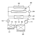
図1に示す冷凍サイクル装置は、車載機器や車室内空間(換言すれば、送風対象空間)を適切な温度に調節するために用いられる車両用冷凍サイクル装置である。本実施形態では、冷凍サイクル装置を、エンジン(換言すれば内燃機関)および走行用電動モータから車両走行用の駆動力を得るハイブリッド自動車に適用している。
図1に示す冷凍サイクル装置は、車載機器や車室内空間(換言すれば、送風対象空間)を適切な温度に調節するために用いられる車両用冷凍サイクル装置である。本実施形態では、冷凍サイクル装置を、エンジン(換言すれば内燃機関)および走行用電動モータから車両走行用の駆動力を得るハイブリッド自動車に適用している。
本実施形態のハイブリッド自動車は、車両停車時に外部電源(換言すれば商用電源)から供給された電力を、車両に搭載された電池(換言すれば車載バッテリ)に充電可能なプラグインハイブリッド自動車として構成されている。電池としては、例えばリチウムイオン電池を用いることができる。
エンジンから出力される駆動力は、車両走行用として用いられるのみならず、発電機を作動させるためにも用いられる。そして、発電機にて発電された電力および外部電源から供給された電力を電池に蓄わえることができ、電池に蓄えられた電力は、走行用電動モータのみならず、冷凍サイクル装置を構成する電動式構成機器をはじめとする各種車載機器に供給される。
冷凍サイクル10は、圧縮機11、高圧側熱交換器12、第1膨張弁13、室外熱交換器14、第2膨張弁15および低圧側熱交換器16を備える蒸気圧縮式冷凍機である。本実施形態の冷凍サイクル10では、冷媒としてフロン系冷媒を用いており、高圧側冷媒圧力が冷媒の臨界圧力を超えない亜臨界冷凍サイクルを構成している。
圧縮機11は、電池から供給される電力によって駆動される電動圧縮機、またはベルトによって駆動されるベルト駆動式圧縮機であり、冷凍サイクル10の冷媒を吸入して圧縮して吐出する。
高圧側熱交換器12は、圧縮機11から吐出された高圧側冷媒と高温冷却水回路20の冷却水とを熱交換させることによって高圧側冷媒を凝縮させる凝縮器である。
高温冷却水回路20の冷却水は、熱媒体としての流体である。高温冷却水回路20の冷却水は高温熱媒体である。高温冷却水回路20は、高温熱媒体が循環する熱媒体回路である。本実施形態では、高温冷却水回路20の冷却水として、少なくともエチレングリコール、ジメチルポリシロキサンもしくはナノ流体を含む液体、または不凍液体が用いられている。
第1膨張弁13は、高圧側熱交換器12から流出した液相冷媒を減圧膨張させる第1減圧部である。第1膨張弁13は、電気式の可変絞り機構であり、弁体と電動アクチュエータとを有している。弁体は、冷媒通路の通路開度(換言すれば絞り開度)を変更可能に構成されている。電動アクチュエータは、弁体の絞り開度を変化させるステッピングモータを有している。
第1膨張弁13は、絞り開度を全開した際に冷媒通路を全開する全開機能付きの可変絞り機構で構成されている。つまり、第1膨張弁13は、冷媒通路を全開にすることで冷媒の減圧作用を発揮させないようにすることができる。第1膨張弁13は、図2に示す制御装置40から出力される制御信号によって、その作動が制御される。
室外熱交換器14は、第1膨張弁13から流出した冷媒と外気とを熱交換させる冷媒外気熱交換器である。室外熱交換器14には、室外送風機17によって外気が送風される。
室外送風機17は、室外熱交換器14へ向けて外気を送風する送風部である。室外送風機17は、ファンを電動モータにて駆動する電動送風機である。室外送風機17は、室外熱交換器14に流入する外気の風速を調節する風速調節部である。
室外熱交換器14および室外送風機17は、車両の最前部に配置されている。従って、車両の走行時には室外熱交換器14に走行風を当てることができるようになっている。
室外熱交換器14を流通する冷媒の温度が外気の温度よりも低い場合、室外熱交換器14は、外気の熱を冷媒に吸熱させる吸熱器として機能する。室外熱交換器14を流通する冷媒の温度が外気の温度よりも高い場合、室外熱交換器14は、冷媒の熱を外気に放熱させる放熱器として機能する。
第2膨張弁15は、室外熱交換器14から流出した液相冷媒を減圧膨張させる第2減圧部である。第2膨張弁15は、電気式の可変絞り機構であり、弁体と電動アクチュエータとを有している。弁体は、冷媒通路の通路開度(換言すれば絞り開度)を変更可能に構成されている。電動アクチュエータは、弁体の絞り開度を変化させるステッピングモータを有している。
第2膨張弁15は、絞り開度を全開した際に冷媒通路を全開する全開機能付きの可変絞り機構で構成されている。つまり、第2膨張弁15は、冷媒通路を全開にすることで冷媒の減圧作用を発揮させないようにすることができる。第2膨張弁15は、図2に示す制御装置40から出力される制御信号によって、その作動が制御される。
第1膨張弁13および第2膨張弁15の絞り開度が変更されることによって、吸熱モードと放熱モードとが切り替えられる。吸熱モードは、室外熱交換器14にて外気から冷媒に吸熱させる作動モードである。放熱モードは、室外熱交換器14にて冷媒から外気に放熱させる作動モードである。
低圧側熱交換器16は、第2膨張弁15を流出した低圧冷媒と低温冷却水回路30の冷却水とを熱交換させることによって低圧冷媒を蒸発させる蒸発器である。低圧側熱交換器16で蒸発した気相冷媒は圧縮機11に吸入されて圧縮される。
低温冷却水回路30の冷却水は、熱媒体としての流体である。低温冷却水回路30の冷却水は低温熱媒体である。低温冷却水回路30は、低温熱媒体が循環する熱媒体回路である。本実施形態では、低温冷却水回路30の冷却水として、少なくともエチレングリコール、ジメチルポリシロキサンもしくはナノ流体を含む液体、または不凍液体が用いられている。
高温冷却水回路20には、高圧側熱交換器12、高温側ポンプ21、ヒータコア22、エンジン23および流量調節バルブ24が配置されている。高温側ポンプ21は、冷却水を吸入して吐出する熱媒体ポンプである。高温側ポンプ21は電動式のポンプである。高温側ポンプ21は、高温冷却水回路20を循環する冷却水の流量を調節する流量調節部である。
ヒータコア22は、高温冷却水回路20の冷却水と車室内(換言すれば、送風対象空間)へ送風される空気とを熱交換させて車室内へ送風される空気を加熱する加熱用熱交換器である。ヒータコア22では、冷却水が顕熱変化にて車室内へ送風される空気に放熱する。すなわち、ヒータコア22では、冷却水が車室内へ送風される空気に放熱しても冷却水が液相のままで相変化しない。
エンジン23は、高温冷却水回路20の冷却水によって温度調節される温調対象機器である。ヒータコア22およびエンジン23は、冷却水の流れにおいて互いに並列に配置されている。
流量調節バルブ24は、ヒータコア22を流れる冷却水と、エンジン23を流れる冷却水との流量割合を調節する流量割合調節部である。流量調節バルブ24は、エンジン23およびヒータコア22に対して、冷却水の流量割合を調節することによって、冷凍サイクル10の高圧側冷媒の熱の供給割合を調節する供給割合調節部である。
高温側ポンプ21および流量調節バルブ24は、高圧側熱交換器12を流れる冷却水の流量を調節する高圧側流量調節部である。高温側ポンプ21および流量調節バルブ24は、エンジン23を流れる冷却水の流量を調節する温調流量調節部である。高温側ポンプ21および流量調節バルブ24は、ヒータコア22を流れる冷却水の流量を調節することによって、ヒータコア22における熱交換量を調節する熱交換量調節部である。
低温冷却水回路30には、低圧側熱交換器16、低温側ポンプ31およびクーラコア32が配置されている。低温側ポンプ31は、冷却水を吸入して吐出する熱媒体ポンプである。低温側ポンプ31は電動式のポンプである。低温側ポンプ31は、低温冷却水回路30を循環する冷却水の流量を調節する低温側流量調節部である。
クーラコア32は、低温冷却水回路30の冷却水と車室内へ送風される空気とを熱交換させて車室内へ送風される空気を冷却する低温側熱媒体熱交換器である。したがって、低圧側熱交換器16は、冷凍サイクル10の低圧側冷媒に、車室内へ送風される空気から間接的に吸熱させる。
クーラコア32では、冷却水が顕熱変化にて車室内へ送風される空気から吸熱する。すなわち、クーラコア32では、冷却水が車室内へ送風される空気から吸熱しても冷却水が液相のままで相変化しない。
クーラコア32およびヒータコア22は、図示しない空調ケーシングに収容されている。空調ケーシングは、空気通路を形成する空気通路形成部材である。空調ケーシングは、車室内最前部に位置する図示しない計器盤の内部に配置されている。ヒータコア22は、空調ケーシング内の空気通路において、クーラコア32の空気流れ下流側に配置されている。
空調ケーシングには、図示しない内外気切替箱と室内送風機33とが配置されている。内外気切替箱は、空調ケーシング内の空気通路に内気と外気とを切替導入する内外気切替部である。室内送風機33は、内外気切替箱によって空調ケーシング内の空気通路に導入された内気および外気を吸入して送風する。
空調ケーシング内の空気通路においてクーラコア32とヒータコア22との間には、図示しないエアミックスドアが配置されている。エアミックスドアは、クーラコア32を通過した冷風のうちヒータコア22に流入する冷風とヒータコア22をバイパスして流れる冷風との風量割合を調節する風量割合調節部である。エアミックスドアの作動は、制御装置40によって制御される。
空調ケーシングには、図示しない吹出口が形成されている。エアミックスドアで所望温度に調整された空調風は吹出口を通じて車室内へ吹き出される。
次に、冷凍サイクル10の電気制御部を図2に基づいて説明する。制御装置40は、CPU、ROMおよびRAM等を含む周知のマイクロコンピュータとその周辺回路から構成されている。制御装置40は、ROM内に記憶された制御プログラムに基づいて各種演算、処理を行う。制御装置40の出力側には各種制御対象機器が接続されている。制御装置40は、各種制御対象機器の作動を制御する制御部である。
制御装置40によって制御される制御対象機器は、圧縮機11、第1膨張弁13、第2膨張弁15、室外送風機17、高温側ポンプ21、低温側ポンプ31および室内送風機33等である。
制御装置40のうち圧縮機11の電動モータを制御するソフトウェアおよびハードウェアは、圧縮機11の冷媒吐出能力を制御する冷媒吐出能力制御部である。制御装置40のうち第1膨張弁13を制御するソフトウェアおよびハードウェアは、第1膨張弁13の絞り開度を制御する第1絞り制御部である。制御装置40のうち第2膨張弁15を制御するソフトウェアおよびハードウェアは、第2膨張弁15の絞り開度を制御する第2絞り制御部である。
制御装置40のうち室外送風機17を制御するソフトウェアおよびハードウェアは、室外送風機17の外気送風能力を制御する外気送風能力制御部である。
制御装置40のうち高温側ポンプ21を制御するソフトウェアおよびハードウェアは、高温側熱媒体の流量を制御する高温側熱媒体流量制御部である。制御装置40のうち低温側ポンプ31を制御するソフトウェアおよびハードウェアは、低温側熱媒体の流量を制御する低温側熱媒体流量制御部である。制御装置40のうち室内送風機33を制御するソフトウェアおよびハードウェアは、室内送風機制御部である。
制御装置40の入力側には、内気温度センサ41、外気温度センサ42、日射量センサ43、室外熱交換器温度センサ44、低圧側熱交換器温度センサ45、エンジン温度センサ46等の種々の空調制御用のセンサ群が接続されている。
内気温度センサ41は内気温度Tr(すなわち車室内温度)を検出する内気温度検出部である。外気温度センサ42は外気温度Tamを検出する外気温度検出部である。日射量センサ43は車室内の日射量Tsを検出する日射量検出部である。室外熱交換器温度センサ44は、室外熱交換器14の温度を検出する室外熱交換器温度検出部である。例えば、室外熱交換器温度センサ44は、室外熱交換器14に流入する冷媒の温度を検出する。低圧側熱交換器温度センサ45は、低圧側熱交換器16から流出した冷却水の温度を検出する。
エンジン温度センサ46は、エンジン23の温度を検出するエンジン温度検出部である。例えば、エンジン温度センサ46は、エンジン23に流入する冷媒の温度を検出する。
制御装置40の入力側には、操作パネル48が接続されている。操作パネル48は、車室内前部の計器盤付近に配置されており、乗員によって操作される。操作パネル48には各種操作スイッチが設けられている。制御装置40には、各種操作スイッチからの操作信号が入力される。
操作パネル48の各種操作スイッチは、エアコンスイッチ48a、温度設定スイッチ等である。エアコンスイッチ48aは、空調の作動・停止(すなわち圧縮機11の作動・停止)を設定する。エアコンスイッチ48aは、車室内へ送風される空気を、低圧側熱交換器16を利用して冷却することを要求するための冷却要求操作部である。温度設定スイッチは、車室内の設定温度を設定するための温度設定操作部である。
次に、上記構成における作動を説明する。制御装置40は、操作パネル48のエアコンスイッチ48aが投入されていることによって圧縮機11が作動している場合、車両用冷凍サイクル装置の作動モードを決定する。制御装置40は、車両用冷凍サイクル装置の作動モードを、エンジン23を暖機する必要の有無、および目標吹出温度TAO等に基づいて決定する。
エンジン23を暖機する必要の有無は、エンジン温度センサ46の検出温度、すなわちエンジン23の温度に基づいて判定する。例えば、エンジン23の温度が所定温度未満である場合、エンジン23を暖機する必要があると判定する。
目標吹出温度TAOは、車室内へ吹き出す吹出空気の目標温度である。制御装置40は、目標吹出温度TAOを以下の数式に基づいて算出する。
TAO=Kset×Tset-Kr×Tr-Kam×Tam-Ks×Ts+C
この数式において、Tsetは操作パネル48の温度設定スイッチによって設定された車室内設定温度、Trは内気温度センサ41によって検出された内気温度、Tamは外気温度センサ42によって検出された外気温度、Tsは日射量センサ43によって検出された日射量である。Kset、Kr、Kam、Ksは制御ゲインであり、Cは補正用の定数である。
この数式において、Tsetは操作パネル48の温度設定スイッチによって設定された車室内設定温度、Trは内気温度センサ41によって検出された内気温度、Tamは外気温度センサ42によって検出された外気温度、Tsは日射量センサ43によって検出された日射量である。Kset、Kr、Kam、Ksは制御ゲインであり、Cは補正用の定数である。
制御装置40は、エンジン23を暖機する必要がなく、かつ目標吹出温度TAOが内気温度Trよりも低い場合、冷房モードを実行する。冷房モードは、室外熱交換器14にて冷凍サイクル10の高圧側冷媒が外気に放熱する放熱モードである。
冷房モードでは、制御装置40は、第1膨張弁13を全開状態とし、第2膨張弁15を絞り状態とする。冷房モードでは、制御装置40は、高温側ポンプ21を停止させ、低温側ポンプ31を駆動させる。
制御装置40は、第2膨張弁15へ流入する冷媒の過冷却度が、予め定められた目標過冷却度に近づくように、または圧縮機11へ流入する冷媒の過熱度が、予め定められた目標過熱度に近づくように、第2膨張弁15の絞り開度を決定する。目標過冷却度および目標過熱度は、サイクルの成績係数(いわゆるCOP)を最大値に近づけるように定められている。
冷房モードでは、圧縮機11から吐出された高圧冷媒が高圧側熱交換器12に流入する。この際、高温側ポンプ22が停止しているので、高圧側熱交換器12に高温冷却水回路20の冷却水が循環しない。そのため、高圧側熱交換器12に流入した冷媒は、高温冷却水回路20の冷却水と殆ど熱交換することなく、高圧側熱交換器12から流出する。
高圧側熱交換器12から流出した冷媒は、第1膨張弁13に流入する。この際、第1膨張弁13が冷媒通路を全開状態としているので、高圧側熱交換器12から流出した冷媒は、第1膨張弁13にて減圧されることなく、室外熱交換器14に流入する。
室外熱交換器14に流入した冷媒は、室外熱交換器14にて室外送風機17によって送風された外気へ放熱する。
室外熱交換器14から流出した冷媒は、第2膨張弁15へ流入して、第2膨張弁15にて低圧冷媒となるまで減圧膨張される。第2膨張弁15にて減圧された低圧冷媒は、低圧側熱交換器16に流入し、低温冷却水回路30の冷却水から吸熱して蒸発する。これにより、低温冷却水回路30の冷却水が冷却されるので、クーラコア32にて室内送風機33によって送風された空気が冷却される。
そして、低圧側熱交換器16から流出した冷媒は、圧縮機11の吸入側へと流れて再び圧縮機11にて圧縮される。
以上の如く、冷房モードでは、クーラコア32にて冷却された空気を車室内へ吹き出すことができる。これにより、車室内の冷房を実現することができる。
制御装置40は、エンジン23を暖機する必要がなく、かつ目標吹出温度TAOが内気温度Trよりも高い場合、暖房モードを実行する。暖房モードは、室外熱交換器14にて冷凍サイクル10の低圧側冷媒が外気から吸熱する吸熱モードである。
暖房モードでは、制御装置40は、第1膨張弁13を絞り状態とし、第2膨張弁15を全開状態とする。暖房モードでは、制御装置40は、高温側ポンプ21を駆動させ、低温側ポンプ31を停止させる。
制御装置40は、第1膨張弁13へ流入する冷媒の過冷却度が、予め定められた目標過冷却度に近づくように、または圧縮機11へ流入する冷媒の過熱度が、予め定められた目標過熱度に近づくように、第1膨張弁13の絞り開度を決定する。
制御装置40は、エアミックスドアがヒータコア22の空気通路を全開し、クーラコア32を通過した送風空気の全流量がヒータコア22の空気通路を通過するようにエアミックスドアの作動状態を決定する。
暖房モードでは、圧縮機11から吐出された高圧冷媒は、高圧側熱交換器12へ流入して、高温冷却水回路20の冷却水と熱交換して放熱する。これにより、高温冷却水回路20の冷却水が加熱される。
高圧側熱交換器12から流出した冷媒は、第1膨張弁13に流入し、低圧冷媒となるまで減圧される。そして、第1膨張弁13にて減圧された低圧冷媒は、室外熱交換器14に流入して、室外送風機17によって送風された外気から吸熱して蒸発する。
室外熱交換器14から流出した冷媒は、第2膨張弁15へ流入する。この際、第2膨張弁15を全開状態としているので、室外熱交換器14から流出した冷媒は、第2膨張弁15にて減圧されることなく、低圧側熱交換器16に流入する。
低温側ポンプ31が停止しているので、低圧側熱交換器16に低温冷却水回路30の冷却水が循環しない。そのため、低圧側熱交換器16に流入した低圧冷媒は、低温冷却水回路30の冷却水から殆ど吸熱しない。そして、低圧側熱交換器16から流出した冷媒は、圧縮機11の吸入側へと流れて再び圧縮機11にて圧縮される。
以上の如く、暖房モードでは、高圧側熱交換器12にて圧縮機11から吐出された高圧冷媒の有する熱を高温冷却水回路20の冷却水に放熱させ、ヒータコア22にて高温冷却水回路20の冷却水が有する熱を車室内へ送風される空気に放熱させて、加熱された空気を車室内へ吹き出すことができる。これにより、車室内の暖房を実現することができる。
制御装置40は、エンジン23を暖機する必要があり、かつ目標吹出温度TAOが内気温度Trよりも低い場合、冷房暖機モードを実行する。冷房暖機モードは、室外熱交換器14にて冷凍サイクル10の低圧側冷媒が外気から吸熱する吸熱モードである。
冷房暖機モードでは、制御装置40は、第1膨張弁13を絞り状態とし、第2膨張弁15を全開状態とする。冷房暖機モードでは、制御装置40は、高温側ポンプ21および低温側ポンプ31を駆動させる。
制御装置40は、第1膨張弁13へ流入する冷媒の過冷却度が、予め定められた目標過冷却度に近づくように第1膨張弁13の絞り開度を決定する。制御装置40は、エンジン23に冷却水が流れるように流量調節バルブ24の作動状態を決定する。
冷房暖機モードでは、圧縮機11から吐出された高圧冷媒は、高圧側熱交換器12へ流入して、高温冷却水回路20の冷却水と熱交換して放熱する。これにより、高温冷却水回路20の冷却水が加熱される。
高圧側熱交換器12から流出した冷媒は、第1膨張弁13に流入し、低圧冷媒となるまで減圧される。そして、第1膨張弁13にて減圧された低圧冷媒は、室外熱交換器14に流入して、室外送風機17によって送風された外気から吸熱して蒸発する。
室外熱交換器14から流出した冷媒は、第2膨張弁15へ流入する。この際、第2膨張弁15を全開状態としているので、室外熱交換器14から流出した冷媒は、第2膨張弁15にて減圧されることなく、低圧側熱交換器16に流入し、低温冷却水回路30の冷却水から吸熱して蒸発する。即ち、冷房暖機モードでは、冷媒が室外熱交換器14と低圧側熱交換器16の両方で吸熱して、蒸発する。
これにより、低温冷却水回路30の冷却水が冷却されるので、クーラコア32にて室内送風機33によって送風された空気が冷却される。そして、低圧側熱交換器16から流出した冷媒は、圧縮機11の吸入側へと流れて再び圧縮機11にて圧縮される。
以上の如く、冷房暖機モードでは、クーラコア32にて冷却された空気を車室内へ吹き出すことができる。これにより、車室内の冷房を実現することができる。
さらに、冷房暖機モードでは、高圧側熱交換器12にて圧縮機11から吐出された高圧冷媒の有する熱を高温冷却水回路20の冷却水に放熱させ、高温冷却水回路20の冷却水が有する熱をエンジン23に放熱させることができる。これにより、エンジン23の暖機を実現することができる。
制御装置40は、エンジン23を暖機する必要があり、かつ目標吹出温度TAOが内気温度Trよりも高い場合、暖房暖機モードを実行する。暖房暖機モードは、室外熱交換器14にて冷凍サイクル10の低圧側冷媒が外気から吸熱する吸熱モードである。
暖房暖機モードでは、制御装置40は、第1膨張弁13を絞り状態とし、第2膨張弁15を全開状態とする。暖房モードでは、制御装置40は、高温側ポンプ21を駆動させ、低温側ポンプ31を停止させる。
制御装置40は、第1膨張弁13へ流入する冷媒の過冷却度が、予め定められた目標過冷却度に近づくように第1膨張弁13の絞り開度を決定する。制御装置40は、ヒータコア22およびエンジン23に冷却水が流れるように流量調節バルブ24の作動状態を決定する。
制御装置40は、エアミックスドアがヒータコア22の空気通路を全開し、クーラコア32を通過した送風空気の全流量がヒータコア22の空気通路を通過するようにエアミックスドアの作動状態を決定する。
暖房暖機モードでは、圧縮機11から吐出された高圧冷媒は、高圧側熱交換器12へ流入して、高温冷却水回路20の冷却水と熱交換して放熱する。これにより、高温冷却水回路20の冷却水が加熱される。
高圧側熱交換器12から流出した冷媒は、第1膨張弁13に流入し、低圧冷媒となるまで減圧される。そして、第1膨張弁13にて減圧された低圧冷媒は、室外熱交換器14に流入して、室外送風機17によって送風された外気から吸熱して蒸発する。
室外熱交換器14から流出した冷媒は、第2膨張弁15へ流入する。この際、第2膨張弁15を全開状態としているので、室外熱交換器14から流出した冷媒は、第2膨張弁15にて減圧されることなく、低圧側熱交換器16に流入する。
低温側ポンプ31が停止しているので、低圧側熱交換器16に低温冷却水回路30の冷却水が循環しない。そのため、低圧側熱交換器16に流入した低圧冷媒は、低温冷却水回路30の冷却水から殆ど吸熱しない。そして、低圧側熱交換器16から流出した冷媒は、圧縮機11の吸入側へと流れて再び圧縮機11にて圧縮される。
以上の如く、暖房暖機モードでは、高圧側熱交換器12にて圧縮機11から吐出された高圧冷媒の有する熱を高温冷却水回路20の冷却水に放熱させ、ヒータコア22にて高温冷却水回路20の冷却水が有する熱を車室内へ送風される空気に放熱させて、加熱された空気を車室内へ吹き出すことができる。これにより、車室内の暖房を実現することができる。
さらに、暖房暖機モードでは、高温冷却水回路20の冷却水が有する熱をエンジン23に放熱させることができる。これにより、エンジン23の暖機を実現することができる。
暖房モード、冷房暖機モードおよび暖房暖機モードにおいて、第2膨張弁15の絞り開度(換言すれば通路面積)を小さくすることによって、室外熱交換器14の圧力が上昇し外気との温度差が小さくなるため、室外熱交換器14の吸熱量が低下する。
暖房モード、冷房暖機モードおよび暖房暖機モードにおいて、第1膨張弁13の絞り開度(換言すれば通路面積)を大きくすることによって、室外熱交換器14の圧力が上昇し外気との温度差が小さくなるため、室外熱交換器14の吸熱量が低下する。
暖房モード、冷房暖機モードおよび暖房暖機モードにおいて、室外送風機17の駆動電力(換言すれば回転数)を低下させることによって、室外熱交換器14を流れる外気の風速が低下するため、室外熱交換器14の吸熱量が低下する。
したがって、第1膨張弁13、第2膨張弁15および室外送風機17は、室外熱交換器14における熱交換量を調節する熱交換量調節部である。具体的には、第1膨張弁13、第2膨張弁15および室外送風機17は、吸熱モード時に、室外熱交換器14において低圧側冷媒が外気から吸熱する吸熱量を調節する吸熱量調節部である。吸熱モードは、室外熱交換器14にて冷凍サイクル10の低圧側冷媒が外気から吸熱する作動モードである。
このように、本実施形態では、制御装置40は、車室内へ送風される空気を冷却することを要求するようにエアコンスイッチ48aが操作されており且つエンジン23を暖機する必要がある場合、吸熱モードになるように第1膨張弁13および第2膨張弁15の作動を制御する。
これによると、車室内へ送風される空気を冷却し且つエンジン23を暖機する場合、室外熱交換器14と低圧側熱交換器16の両方で冷凍サイクル10の低圧側冷媒に吸熱させることができる。
そのため、車室内へ送風される空気を冷却できるとともに、室外熱交換器14にて冷媒から外気に放熱する場合と比較してエンジン23を暖機する能力を高くできるので、車室内へ送風される空気の冷却とエンジン23の暖機とを両立できる。
例えば、制御装置40は、第1膨張弁13および第2膨張弁15が吸熱モードに切り替えた後、時間が経過するにつれて、室外熱交換器14において低圧側冷媒が外気から吸熱する吸熱量が少なくなるように第1膨張弁13、第2膨張弁15および室外送風機17のうち少なくとも1つの作動を制御する。
これによると、エンジン23の暖機が進むにつれて、エンジン23に供給される熱量が少なくなるので、エンジン23が過剰に暖機されることを抑制できる。
例えば、制御装置40は、第1膨張弁13および第2膨張弁15が吸熱モードに切り替えた後、所定時間が経過した場合、放熱モードに切り替わるように第1膨張弁13および第2膨張弁15の作動を制御する。放熱モードは、室外熱交換器14にて冷凍サイクル10の高圧側冷媒が外気に放熱する作動モードである。
これによると、エンジン23の暖機に必要な熱量が少なくなった場合、低圧側熱交換器16での吸熱量を増加させて、車室内へ送風される空気の冷却能力を高めることができる。
例えば、制御装置40は、第1膨張弁13および第2膨張弁15が吸熱モードに切り替えた後、時間が経過するにつれて、ヒータコア22に対する高圧側冷媒の熱の供給割合(具体的には、ヒータコア22に対する冷却水の供給割合)が増加するように流量調節バルブ24の作動を制御する。
これによると、吸熱モードに切り替えた直後はエンジン23の暖機が優先されるので、エンジン23の暖機を速やかに行うことができる。
例えば、制御装置40は、第1膨張弁13および第2膨張弁15が吸熱モードに切り替えた後、時間が経過するにつれて、ヒータコア22における熱交換量(具体的には、ヒータコア22を流れる冷却水の流量)が増加するように流量調節バルブ24の作動を制御する。
これによると、エンジン23の暖機に必要な熱量が少なくなるにつれて、車室内へ送風される空気の加熱能力を高めることができる。
例えば、制御装置40は、第1膨張弁13および第2膨張弁15が吸熱モードに切り替えた後、時間が経過するにつれて、高圧側熱交換器12、室外熱交換器14、低圧側熱交換器16およびヒータコア22の熱交換絶対量の比較におけるヒータコア22の熱交換絶対量の順位が上がるように高温側ポンプ21および流量調節バルブ24のうち少なくとも1つの作動を制御する。ここで、熱交換絶対量の順位とは、熱交換絶対量の多い方からの順位のことである。
これによると、エンジン23の暖機に必要な熱量が少なくなるにつれて、車室内へ送風される空気の加熱能力を高めることができる。
例えば、制御装置40は、第1膨張弁13および第2膨張弁15が吸熱モードに切り替えた後、時間が経過するにつれて、高圧側熱交換器12、室外熱交換器14、低圧側熱交換器16およびヒータコア22の熱交換絶対量の比較における室外熱交換器14の熱交換絶対量の順位が下がるように第1膨張弁13、第2膨張弁15および室外送風機17のうち少なくとも1つの作動を制御する。ここで、熱交換絶対量の順位とは、熱交換絶対量の多い方からの順位のことである。
これによると、エンジン23の暖機が進むにつれて、室外熱交換器14で低圧側冷媒に吸熱される熱量を少なくすることができるので、高圧側熱交換器12の能力が過剰になることを抑制できる。
例えば、制御装置40は、第1膨張弁13および第2膨張弁15が吸熱モードに切り替えた後、時間が経過するにつれて、高圧側熱交換器12、室外熱交換器14、低圧側熱交換器16およびヒータコア22の熱交換絶対量を比較して低圧側熱交換器16の熱交換絶対量の順位が上がるように低温側ポンプ31の作動を制御する。
これによると、乗員の呼気や発汗によって車室内の水分量が多くなるにつれて、低圧側熱交換器16の除湿能力を高めることができるので、車室内の湿度が上昇することを抑制できる。
本実施形態では、制御装置40は、低圧側熱交換器16で要求される熱交換量に応じて圧縮機11の冷媒吐出能力を制御する。具体的には、制御装置40は、低圧側熱交換器16の温度が低圧側熱交換器16の目標温度に近づくように圧縮機11の冷媒吐出能力を制御する。
例えば、制御装置40は、吸熱モードにおいて、圧縮機11の冷媒吐出能力が最大であっても低圧側熱交換器16の熱交換量が低圧側熱交換器16で要求される熱交換量よりも少ないと判断される場合、室外熱交換器14の吸熱量が減少するように第1膨張弁13、第2膨張弁15および室外送風機17のうち少なくとも1つの作動を制御する。低圧側熱交換器16の熱交換量が低圧側熱交換器16で要求される熱交換量よりも少ないと判断される場合とは、例えば、低圧側熱交換器16の温度が低圧側熱交換器16の目標温度に近づかない場合である。
これによると、圧縮機11の冷媒吐出能力が最大である場合、低圧側熱交換器16の熱交換量をさらに増加させることができるので、低圧側熱交換器の熱交換量が、要求される熱交換量に対して不足することを抑制できる。
例えば、制御装置40は、吸熱モードにおいて、圧縮機11の冷媒吐出能力が最大であっても低圧側熱交換器16の熱交換量が低圧側熱交換器16で要求される熱交換量よりも少ないと判断される場合、放熱モードに切り替わるように第1膨張弁13および第2膨張弁15の作動を制御する。
これによると、圧縮機11の冷媒吐出能力が最大である場合、低圧側熱交換器16の熱交換量をさらに増加させることができるので、低圧側熱交換器の熱交換量が、要求される熱交換量に対して不足することを抑制できる。
例えば、制御装置40は、高圧側熱交換器12に流入する冷却水の温度が高くなるほど高圧側熱交換器12を流れる冷却水の流量が減少するように高温側ポンプ21および流量調節バルブ24のうち少なくとも1つの作動を制御する。
これによると、高圧側熱交換器12に流入する冷却水の温度が高くなっても冷凍サイクル10の高圧が上昇することを抑制できるので、圧縮機11の消費動力が過剰になったり低圧側熱交換器16において冷却水を冷却する能力が低下したりすることを抑制できる。
例えば、制御装置40は、エンジン23の温度が高くなるにつれてエンジン23を流れる冷却水の流量が増加するように高温側ポンプ21および流量調節バルブ24のうち少なくとも1つの作動を制御する。
これによると、エンジン23の温度が低い場合、エンジン23を流れる冷却水の流量を少なくしてエンジン23の温度上昇量を上げ、エンジン23の温度が高くなるにつれてエンジン23を流れる冷却水の流量を多くしてエンジン23の温度上昇量を下げることができる。
(第2実施形態)
上記実施形態では、低圧側熱交換器16およびクーラコア32によって低圧冷媒と車室内へ送風される空気とを熱交換させるが、本実施形態では、図3に示すように、低圧側熱交換器50によって低圧冷媒と車室内へ送風される空気とを熱交換させる。
上記実施形態では、低圧側熱交換器16およびクーラコア32によって低圧冷媒と車室内へ送風される空気とを熱交換させるが、本実施形態では、図3に示すように、低圧側熱交換器50によって低圧冷媒と車室内へ送風される空気とを熱交換させる。
すなわち、上記実施形態では、低圧側熱交換器16は、冷凍サイクル10の低圧側冷媒に、車室内へ送風される空気から間接的に吸熱させるが、本実施形態では、低圧側熱交換器50は、冷凍サイクル10の低圧側冷媒に、車室内へ送風される空気から直接的に吸熱させる。
低圧側熱交換器50は、第2膨張弁15を流出した低圧冷媒と車室内へ送風される空気とを熱交換させて低圧冷媒を蒸発させる蒸発器である。低圧側熱交換器50は、第2膨張弁15を流出した低圧冷媒と車室内へ送風される空気とを熱交換させて車室内へ送風される空気を冷却する低温側熱媒体熱交換器である。
本実施形態においても、上記実施形態と同様の作用効果を奏することができる。
(第3実施形態)
本実施形態では、図4に示すように、冷凍サイクル10は、バイパス部51およびバイパス流量調節弁52を備える。
バイパス部51は、冷媒が室外熱交換器14をバイパスして流れる冷媒流路を形成している。バイパス流量調節弁52は、バイパス部51の流路開度を調節する開度調節弁である。
バイパス流量調節弁52は、バイパス部51を流れる冷媒の流量を調節することによって室外熱交換器14を流れる冷媒の流量を調節する。バイパス流量調節弁52は、室外熱交換器14およびバイパス部51に対して、高圧側冷媒または低圧側冷媒の流量割合を調節するバイパス調節部である。バイパス流量調節弁52の作動は、制御装置40によって制御される。
本実施形態では、図4に示すように、冷凍サイクル10は、バイパス部51およびバイパス流量調節弁52を備える。
バイパス部51は、冷媒が室外熱交換器14をバイパスして流れる冷媒流路を形成している。バイパス流量調節弁52は、バイパス部51の流路開度を調節する開度調節弁である。
バイパス流量調節弁52は、バイパス部51を流れる冷媒の流量を調節することによって室外熱交換器14を流れる冷媒の流量を調節する。バイパス流量調節弁52は、室外熱交換器14およびバイパス部51に対して、高圧側冷媒または低圧側冷媒の流量割合を調節するバイパス調節部である。バイパス流量調節弁52の作動は、制御装置40によって制御される。
バイパス流量調節弁52がバイパス部51の開度を大きくしてバイパス部51を流れる冷媒の流量を増加させることによって室外熱交換器14を流れる冷媒の流量が減少するため、室外熱交換器14の熱交換量が低下する。
したがって、バイパス流量調節弁52は、室外熱交換器14における熱交換量を調節する熱交換量調節部である。具体的には、バイパス流量調節弁52は、吸熱モード時に、室外熱交換器14において低圧側冷媒が外気から吸熱する吸熱量を調節する吸熱量調節部である。
本実施形態においても、上記実施形態と同様に、室外熱交換器14の熱交換量を調節できる。
(第4実施形態)
上記実施形態では、流量調節バルブ24によって、ヒータコア22を流れる冷却水とエンジン23を流れる冷却水との流量割合を調節するが、本実施形態では、図5に示すように、ヒータコア側遮断弁53によって、ヒータコア22を流れる冷却水とエンジン23を流れる冷却水との流量割合を調節する。
上記実施形態では、流量調節バルブ24によって、ヒータコア22を流れる冷却水とエンジン23を流れる冷却水との流量割合を調節するが、本実施形態では、図5に示すように、ヒータコア側遮断弁53によって、ヒータコア22を流れる冷却水とエンジン23を流れる冷却水との流量割合を調節する。
ヒータコア側遮断弁53は、高温冷却水回路20において、ヒータコア22側の冷却水流路を開閉する開閉弁である。ヒータコア側遮断弁53は、エンジン23およびヒータコア22に対して、冷凍サイクル10の高圧側冷媒の熱の供給割合を調節する供給割合調節部である。ヒータコア側遮断弁53は、ヒータコア22における熱交換量を調節する熱交換量調節部である。
ヒータコア側遮断弁53は、制御装置40から出力される制御信号によって、その作動が制御される。
ヒータコア側遮断弁53は、エンジン23の暖機時に、高温冷却水回路20においてヒータコア22側の冷却水流路を閉じる。これにより、ヒータコア22への冷却水の流れが遮断され、高温側ポンプ21から吐出された冷却水の全量がエンジン23を流れる。そのため、エンジン23の暖機能力を向上できる。
(第5実施形態)
上記第4実施形態では、高温冷却水回路20は、ヒータコア22側の冷却水流路を開閉するヒータコア側遮断弁53を有しているが、本実施形態では、図6に示すように、高温冷却水回路20は、エンジン23側の冷却水流路を開閉するエンジン側遮断弁54を有している。
上記第4実施形態では、高温冷却水回路20は、ヒータコア22側の冷却水流路を開閉するヒータコア側遮断弁53を有しているが、本実施形態では、図6に示すように、高温冷却水回路20は、エンジン23側の冷却水流路を開閉するエンジン側遮断弁54を有している。
エンジン23は、高温冷却水回路20の冷却水流れにおいてヒータコア22と直列に配置されている。高温冷却水回路20は、エンジンバイパス部55を有している。エンジンバイパス部55は、冷却水がエンジン23をバイパスして流れる冷却水流路を形成している。
エンジン側遮断弁54は、高温冷却水回路20において、エンジン23側の冷却水流路を開閉する開閉弁である。エンジン側遮断弁54は、エンジン23を流れる冷却水の流量を調節する温調流量調節部である。エンジン側遮断弁54は、エンジン23およびヒータコア22に対して、冷凍サイクル10の高圧側冷媒の熱の供給割合を調節する供給割合調節部である。エンジン側遮断弁54の作動は、制御装置40によって制御される。
エンジン側遮断弁54がエンジンバイパス部55の開度を小さくすることによってエンジン23を流れる冷却水の流量が減少する。したがって、エンジン23を流れる冷却水の流量を調節できる。
(第6実施形態)
本実施形態では、図7に示すように、室外熱交換器14および低圧側熱交換器16が、冷凍サイクル10の冷媒流れにおいて互いに並列に配置されている。
本実施形態では、図7に示すように、室外熱交換器14および低圧側熱交換器16が、冷凍サイクル10の冷媒流れにおいて互いに並列に配置されている。
冷凍サイクル10は、第1膨張弁56および第2膨張弁57を備える。第1膨張弁56は、高圧側熱交換器12から流出して室外熱交換器14に流入する液相冷媒を減圧膨張させる第1減圧部である。第2膨張弁57は、高圧側熱交換器12から流出して低圧側熱交換器16に流入する液相冷媒を減圧膨張させる第2減圧部である。
高圧側熱交換器12から流出した液相冷媒は、第1膨張弁56側と第2膨張弁57側とに分岐して流れる。第1膨張弁56で減圧された冷媒は室外熱交換器14に流入する。第2膨張弁57で減圧された冷媒は低圧側熱交換器16に流入する。室外熱交換器14で蒸発した気相冷媒および低圧側熱交換器16で蒸発した気相冷媒は、互いに合流して圧縮機11に吸入される。
第1膨張弁56および第2膨張弁57は、電気式の可変絞り機構である。第1膨張弁56および第2膨張弁57の作動は制御装置40によって制御される。
制御装置40は、第1膨張弁56および第2膨張弁57のうち少なくとも1つの絞り開度を制御することによって、室外熱交換器14を流れる冷媒と低圧側熱交換器16を流れる冷媒との流量割合を調節する。これにより、室外熱交換器14において低圧側冷媒が外気から吸熱する吸熱量を調節できる。
図8に示す変形例のように、冷凍サイクル10は、低圧側熱交換器16で蒸発した気相冷媒を減圧膨張させる第3膨張弁58を備えていてもよい。第3膨張弁58は、電気式の可変絞り機構である。第3膨張弁58の作動は制御装置40によって制御される。
この変形例では、室外熱交換器14で蒸発した気相冷媒および第3膨張弁58で減圧膨張された気相冷媒は、互いに合流して圧縮機11に吸入される。
第3膨張弁58を備えることによって、低圧側熱交換器16の冷媒圧力を室外熱交換器14の冷媒圧力よりも高くすることができる。そのため、外気温度が0℃以下のときに低温冷却水回路30の冷却水温度が0℃以下に低下してクーラコア32でフロストが発生してしまうことを抑制できる。
(他の実施形態)
上記実施形態を適宜組み合わせ可能である。上記実施形態を例えば以下のように種々変形可能である。
上記実施形態を適宜組み合わせ可能である。上記実施形態を例えば以下のように種々変形可能である。
(1)室外熱交換器14の近傍にシャッターが配置されていてもよい。シャッターは、電動アクチュエータによって開閉駆動される。電動アクチュエータの作動は制御装置40によって制御される。
シャッターは、室外熱交換器14を流れる外気の通路の開度を調節する。すなわち、シャッターは、室外熱交換器14を流れる外気の流量を調節することによって、室外熱交換器14における熱交換量を調節する熱交換量調節部である。具体的には、シャッターは、吸熱モード時に、室外熱交換器14において低圧側冷媒が外気から吸熱する吸熱量を調節する吸熱量調節部である。
例えば、シャッター41の開度を小さくすることによって、室外熱交換器14を流れる外気の流量を減少させることができる。これにより、室外熱交換器14における熱交換量を低下させることができる。
(2)高温冷却水回路20において、ヒータコア22用のポンプとエンジン23用のポンプとが設けられていてもよい。ヒータコア22用のポンプおよびエンジン23用のポンプは、エンジン23およびヒータコア22に対して、冷凍サイクル10の高圧側冷媒の熱の供給割合を調節する供給割合調節部である。
すなわち、制御装置40がヒータコア22用のポンプの回転数とエンジン23用のポンプの回転数とを独立して制御することによって、ヒータコア22を流れる冷却水とエンジン23を流れる冷却水との流量割合を調節することができる。
(3)上記実施形態では、高温冷却水回路20には、温調対象機器としてエンジン23が配置されているが、温調対象機器として、所定の温度に到達しないと機能を果たせない機器(例えばEGRクーラ)や、温度が高いほど性能が上昇する機器(例えばリチウムイオンバッテリ)等が配置されていてもよい。
(4)上記各実施形態では、温調対象機器を温度調節するための熱媒体として冷却水を用いているが、油などの各種媒体を熱媒体として用いてもよい。
熱媒体として、ナノ流体を用いてもよい。ナノ流体とは、粒子径がナノメートルオーダーのナノ粒子が混入された流体のことである。ナノ粒子を熱媒体に混入させることで、エチレングリコールを用いた冷却水のように凝固点を低下させて不凍液にする作用効果に加えて、次のような作用効果を得ることができる。
すなわち、特定の温度帯での熱伝導率を向上させる作用効果、熱媒体の熱容量を増加させる作用効果、金属配管の防食効果やゴム配管の劣化を防止する作用効果、および極低温での熱媒体の流動性を高める作用効果を得ることができる。
このような作用効果は、ナノ粒子の粒子構成、粒子形状、配合比率、付加物質によって様々に変化する。
これによると、熱伝導率を向上させることができるので、エチレングリコールを用いた冷却水と比較して少ない量の熱媒体であっても同等の冷却効率を得ることが可能になる。
また、熱媒体の熱容量を増加させることができるので、熱媒体自体の顕熱による蓄冷熱量を増加させることができる。
蓄冷熱量を増加させることにより、圧縮機11を作動させない状態であっても、ある程度の時間は蓄冷熱を利用した機器の冷却、加熱の温調が実施できるため、車両用冷凍サイクル装置の省動力化が可能になる。
ナノ粒子のアスペクト比は50以上であるのが好ましい。十分な熱伝導率を得ることができるからである。なお、アスペクト比は、ナノ粒子の縦×横の比率を表す形状指標である。
ナノ粒子としては、Au、Ag、CuおよびCのいずれかを含むものを用いることができる。具体的には、ナノ粒子の構成原子として、Auナノ粒子、Agナノワイヤー、CNT、グラフェン、グラファイトコアシェル型ナノ粒子、およびAuナノ粒子含有CNTなどを用いることができる。
CNTはカーボンナノチューブである。グラファイトコアシェル型ナノ粒子は、上記原子を囲むようにカーボンナノチューブ等の構造体があるような粒子体である。
(5)上記各実施形態の冷凍サイクル10では、冷媒としてフロン系冷媒を用いているが、冷媒の種類はこれに限定されるものではなく、二酸化炭素等の自然冷媒や炭化水素系冷媒等を用いてもよい。
また、上記各実施形態の冷凍サイクル10は、高圧側冷媒圧力が冷媒の臨界圧力を超えない亜臨界冷凍サイクルを構成しているが、高圧側冷媒圧力が冷媒の臨界圧力を超える超臨界冷凍サイクルを構成していてもよい。
(6)上記実施形態では、車両に用いられる冷凍サイクル装置について説明したが、これに限定されず、例えば、上記実施形態を据え置き型の冷凍サイクル装置に変形可能である。
Claims (16)
- 高圧側冷媒を放熱させる高圧側熱交換器(12)と、
低圧側冷媒に、送風対象空間へ送風される空気から直接的または間接的に吸熱させる低圧側熱交換器(16、50)と、
前記高圧側冷媒の熱によって温度調節される温調対象機器(23)と、
前記高圧側冷媒または前記低圧側冷媒と外気とを熱交換させる室外熱交換器(14)と、
前記室外熱交換器にて前記高圧側冷媒が前記外気に放熱する放熱モードと、前記室外熱交換器にて前記低圧側冷媒が前記外気から吸熱する吸熱モードとを切り替える切替部(13、15)と、
前記送風対象空間へ送風される空気を、前記低圧側熱交換器を利用して冷却することを要求するために乗員によって操作される冷却要求操作部(48a)と、
前記送風対象空間へ送風される空気を冷却することを要求するように前記冷却要求操作部が操作されており且つ前記温調対象機器を暖機する必要がある場合、前記吸熱モードになるように前記切替部の作動を制御する制御部(40)とを備える冷凍サイクル装置。 - 前記室外熱交換器において前記低圧側冷媒が前記外気から吸熱する吸熱量を調節する吸熱量調節部(13、15、17、52)を備え、
前記制御部は、前記切替部が前記吸熱モードに切り替えた後、時間が経過するにつれて前記吸熱量が少なくなるように前記吸熱量調節部の作動を制御する請求項1に記載の冷凍サイクル装置。 - 前記制御部は、前記切替部が前記吸熱モードに切り替えた後、所定時間が経過した場合、前記放熱モードに切り替わるように前記切替部の作動を制御する請求項1または2に記載の冷凍サイクル装置。
- 前記送風対象空間へ送風される空気を、前記高圧側冷媒の熱を利用して加熱する加熱用熱交換器(22)と、
前記温調対象機器および前記加熱用熱交換器に対して、前記高圧側冷媒の熱の供給割合を調節する供給割合調節部(24、53、54)とを備え、
前記制御部は、前記切替部が前記吸熱モードに切り替えた後、時間が経過するにつれて、前記加熱用熱交換器に対する前記高圧側冷媒の熱の供給割合が増加するように前記供給割合調節部の作動を制御する請求項1ないし3のいずれか1つに記載の冷凍サイクル装置。 - 前記送風対象空間へ送風される空気を、前記高圧側冷媒の熱を利用して加熱する加熱用熱交換器(22)と、
前記加熱用熱交換器における熱交換量を調節する熱交換量調節部(24、53)とを備え、
前記制御部は、前記切替部が前記吸熱モードに切り替えた後、時間が経過するにつれて、前記加熱用熱交換器における前記熱交換量が増加するように前記熱交換量調節部の作動を制御する請求項1ないし3のいずれか1つに記載の冷凍サイクル装置。 - 前記送風対象空間へ送風される空気を、前記高圧側冷媒の熱を利用して加熱する加熱用熱交換器(22)と、
前記加熱用熱交換器における熱交換量を調節する熱交換量調節部(21、24、53)とを備え、
前記制御部は、前記切替部が前記吸熱モードに切り替えた後、時間が経過するにつれて、前記高圧側熱交換器、前記室外熱交換器、前記低圧側熱交換器および前記加熱用熱交換器の熱交換絶対量の比較における前記加熱用熱交換器の熱交換絶対量の順位が上がるように前記熱交換量調節部の作動を制御する請求項1ないし3のいずれか1つに記載の冷凍サイクル装置。 - 前記送風対象空間へ送風される空気を、前記高圧側冷媒の熱を利用して加熱する加熱用熱交換器(22)と、
前記室外熱交換器において前記低圧側冷媒が前記外気から吸熱する吸熱量を調節する吸熱量調節部(13、15、17、52)とを備え、
前記制御部は、前記切替部が前記吸熱モードに切り替えた後、時間が経過するにつれて、前記高圧側熱交換器、前記室外熱交換器、前記低圧側熱交換器および前記加熱用熱交換器の熱交換絶対量の比較における前記室外熱交換器の熱交換絶対量の順位が下がるように前記吸熱量調節部の作動を制御する請求項1に記載の冷凍サイクル装置。 - 前記送風対象空間へ送風される空気を、前記高圧側冷媒の熱を利用して加熱する加熱用熱交換器(22)と、
前記低圧側熱交換器における熱交換量を調節する熱交換量調節部(31)とを備え、
前記制御部は、前記切替部が前記吸熱モードに切り替えた後、時間が経過するにつれて、前記高圧側熱交換器、前記室外熱交換器、前記低圧側熱交換器および前記加熱用熱交換器の熱交換絶対量を比較して前記低圧側熱交換器の熱交換絶対量の順位が上がるように前記熱交換量調節部の作動を制御する請求項1ないし3のいずれか1つに記載の冷凍サイクル装置。 - 前記室外熱交換器において前記低圧側冷媒が前記外気から吸熱する吸熱量を調節する吸熱量調節部(13、15、17、52)を備え、
前記制御部は、
前記低圧側熱交換器で要求される熱交換量に応じて前記圧縮機の冷媒吐出能力を制御し、
前記吸熱モードにおいて、前記圧縮機の冷媒吐出能力が最大であっても前記低圧側熱交換器の熱交換量が前記低圧側熱交換器で要求される熱交換量よりも少ないと判断される場合、前記室外熱交換器の吸熱量が減少するように前記吸熱量調節部の作動を制御する請求項1に記載の冷凍サイクル装置。 - 前記制御部は、
前記低圧側熱交換器で要求される熱交換量に応じて前記圧縮機の冷媒吐出能力を制御し、
前記吸熱モードにおいて、前記圧縮機の冷媒吐出能力が最大であっても前記低圧側熱交換器の熱交換量が前記低圧側熱交換器で要求される熱交換量よりも少ないと判断される場合、前記放熱モードに切り替わるように前記切替部の作動を制御する請求項1ないし9のいずれか1つに記載の冷凍サイクル装置。 - 前記高圧側熱交換器と前記温調対象機器との間で熱媒体を循環させる熱媒体回路(20)と、
前記高圧側熱交換器を流れる前記熱媒体の流量を調節する高圧側流量調節部(21、24)とを備え、
前記制御部は、前記高圧側熱交換器に流入する前記熱媒体の温度が高くなるほど前記高圧側熱交換器を流れる前記熱媒体の流量が減少するように前記高圧側流量調節部の作動を制御する請求項1ないし10のいずれか1つに記載の冷凍サイクル装置。 - 前記吸熱量調節部は、前記室外熱交換器に流入する前記冷媒、または前記室外熱交換器から流出して前記低圧側熱交換器に流入する前記冷媒を減圧させる減圧部(13、15)である請求項2、7、9のいずれか1つに記載の冷凍サイクル装置。
- 前記吸熱量調節部は、前記室外熱交換器に流入する前記外気の風速を調節する風速調節部(17)である請求項2、7、9のいずれか1つに記載の冷凍サイクル装置。
- 前記室外熱交換器および前記低圧側熱交換器は、前記冷媒の流れにおいて互いに並列に接続されており、
前記室外熱交換器に流入する前記冷媒を減圧させる第1減圧部(56)と、
前記低圧側熱交換器に流入する前記冷媒を減圧させる第2減圧部(57)とを備え、
前記制御部は、前記第1減圧部および前記第2減圧部のうち少なくとも1つを制御することによって、前記室外熱交換器を流れる前記冷媒と前記低圧側熱交換器を流れる前記冷媒との流量割合を調節する請求項1ないし8のいずれか1つに記載の冷凍サイクル装置。 - 前記高圧側冷媒または前記低圧側冷媒が前記室外熱交換器をバイパスして流れるバイパス部(51)を備え、
前記吸熱量調節部は、前記室外熱交換器および前記バイパス部に対して、前記高圧側冷媒または前記低圧側冷媒の流量割合を調節するバイパス調節部(52)である請求項2、7、9のいずれか1つに記載の冷凍サイクル装置。 - 前記高圧側熱交換器と前記温調対象機器との間で熱媒体を循環させる熱媒体回路(20)と、
前記温調対象機器を流れる前記熱媒体の流量を調節する温調流量調節部(21、24、54)とを備え、
前記制御部は、前記温調対象機器の温度が高くなるにつれて前記温調対象機器を流れる前記熱媒体の流量が増加するように前記温調流量調節部の作動を制御する請求項1ないし15のいずれか1つに記載の冷凍サイクル装置。
Priority Applications (3)
| Application Number | Priority Date | Filing Date | Title |
|---|---|---|---|
| DE112017001220.1T DE112017001220T5 (de) | 2016-03-08 | 2017-02-24 | Kühlzyklusvorrichtung |
| US16/082,294 US10899195B2 (en) | 2016-03-08 | 2017-02-24 | Refrigeration cycle device |
| CN201780015672.1A CN108779942B (zh) | 2016-03-08 | 2017-02-24 | 制冷循环装置 |
Applications Claiming Priority (2)
| Application Number | Priority Date | Filing Date | Title |
|---|---|---|---|
| JP2016044318A JP6485390B2 (ja) | 2016-03-08 | 2016-03-08 | 冷凍サイクル装置 |
| JP2016-044318 | 2016-03-08 |
Publications (1)
| Publication Number | Publication Date |
|---|---|
| WO2017154602A1 true WO2017154602A1 (ja) | 2017-09-14 |
Family
ID=59790444
Family Applications (1)
| Application Number | Title | Priority Date | Filing Date |
|---|---|---|---|
| PCT/JP2017/006965 Ceased WO2017154602A1 (ja) | 2016-03-08 | 2017-02-24 | 冷凍サイクル装置 |
Country Status (5)
| Country | Link |
|---|---|
| US (1) | US10899195B2 (ja) |
| JP (1) | JP6485390B2 (ja) |
| CN (1) | CN108779942B (ja) |
| DE (1) | DE112017001220T5 (ja) |
| WO (1) | WO2017154602A1 (ja) |
Cited By (3)
| Publication number | Priority date | Publication date | Assignee | Title |
|---|---|---|---|---|
| WO2019065039A1 (ja) * | 2017-09-28 | 2019-04-04 | 株式会社デンソー | 冷凍サイクル装置 |
| JP2019119437A (ja) * | 2018-01-10 | 2019-07-22 | 株式会社デンソー | 車両用冷却システム |
| CN111727350A (zh) * | 2018-04-13 | 2020-09-29 | 阿科玛法国公司 | 用于冷却和/或加热机动车辆中的物体或流体的方法 |
Families Citing this family (21)
| Publication number | Priority date | Publication date | Assignee | Title |
|---|---|---|---|---|
| JP6418779B2 (ja) * | 2014-05-08 | 2018-11-07 | サンデンホールディングス株式会社 | 車両用空気調和装置 |
| JP6738157B2 (ja) * | 2016-02-26 | 2020-08-12 | サンデン・オートモーティブクライメイトシステム株式会社 | 車両用空気調和装置 |
| JP6673294B2 (ja) * | 2016-08-30 | 2020-03-25 | 株式会社デンソー | 冷凍サイクル装置 |
| JP6627827B2 (ja) * | 2017-07-10 | 2020-01-08 | トヨタ自動車株式会社 | 熱交換システムの制御装置 |
| JP6610621B2 (ja) * | 2017-07-10 | 2019-11-27 | トヨタ自動車株式会社 | 熱交換システムの制御装置 |
| JP6610622B2 (ja) * | 2017-07-10 | 2019-11-27 | トヨタ自動車株式会社 | 熱交換システムの制御装置 |
| JP6627826B2 (ja) | 2017-07-10 | 2020-01-08 | トヨタ自動車株式会社 | 熱交換システムの制御装置 |
| JP6791052B2 (ja) * | 2017-07-31 | 2020-11-25 | 株式会社デンソー | 空調装置 |
| JP6838535B2 (ja) * | 2017-09-21 | 2021-03-03 | 株式会社デンソー | 冷凍サイクル装置 |
| JP6984439B2 (ja) * | 2018-01-25 | 2021-12-22 | 株式会社デンソー | 電池冷却用冷凍サイクル装置 |
| JP6925288B2 (ja) * | 2018-01-30 | 2021-08-25 | サンデン・オートモーティブクライメイトシステム株式会社 | 車両用空気調和装置 |
| CN108895691B (zh) * | 2018-08-14 | 2023-09-26 | 中节能城市节能研究院有限公司 | 一种制冷过冷循环与蓄冷循环联合供能装置及方法 |
| KR102614152B1 (ko) * | 2018-11-09 | 2023-12-13 | 현대자동차주식회사 | 히트펌프 시스템 |
| JP7434847B2 (ja) * | 2018-12-26 | 2024-02-21 | 株式会社デンソー | 冷凍サイクル装置および流量調整機構 |
| JP7543657B2 (ja) * | 2019-03-29 | 2024-09-03 | 株式会社デンソー | 空調装置 |
| JP7230642B2 (ja) * | 2019-03-29 | 2023-03-01 | 株式会社デンソー | 冷凍サイクル装置 |
| CN112406494B (zh) * | 2019-08-23 | 2022-08-09 | 华为技术有限公司 | 用于汽车的热管理系统以及基于该系统的热管理方法 |
| DE102019213860A1 (de) * | 2019-09-11 | 2021-03-11 | Mahle International Gmbh | Klimatisierungssystem für ein Kraftfahrzeug |
| DE102020204555A1 (de) * | 2020-04-08 | 2021-10-14 | Denso Corporation | Kühlkreislauf mit mehreren Kühltemperaturen für Kraftfahrzeuge und ein Verfahren zum Betrieb eines solchen Kühlkreislaufs |
| JP2024030575A (ja) * | 2022-08-24 | 2024-03-07 | サンデン株式会社 | 車両用熱管理装置 |
| WO2026078959A1 (ja) * | 2024-10-07 | 2026-04-16 | 株式会社デンソー | 冷凍サイクル装置 |
Citations (4)
| Publication number | Priority date | Publication date | Assignee | Title |
|---|---|---|---|---|
| JP2006321389A (ja) * | 2005-05-19 | 2006-11-30 | Denso Corp | 車両用廃熱利用装置 |
| JP2010243001A (ja) * | 2009-04-02 | 2010-10-28 | Green Seiju:Kk | 自律平衡型ヒートポンプユニット |
| JP2014037959A (ja) * | 2012-07-18 | 2014-02-27 | Denso Corp | 冷凍サイクル装置 |
| JP2015203394A (ja) * | 2014-04-16 | 2015-11-16 | トヨタ自動車株式会社 | 車両およびその制御方法 |
Family Cites Families (12)
| Publication number | Priority date | Publication date | Assignee | Title |
|---|---|---|---|---|
| DE60031808T2 (de) * | 1999-07-26 | 2007-09-20 | Denso Corp., Kariya | Kühlkreisvorrichtung |
| EP1441121A2 (en) * | 2003-01-27 | 2004-07-28 | Denso Corporation | Vapor-compression refrigerant cycle system with refrigeration cycle and rankine cycle |
| DE102005032277B4 (de) * | 2004-07-12 | 2019-08-14 | Denso Corporation | Dampfkompressionskälteerzeuger |
| JP2006188156A (ja) * | 2005-01-06 | 2006-07-20 | Denso Corp | 蒸気圧縮式冷凍機 |
| JP4801810B2 (ja) * | 2006-05-30 | 2011-10-26 | 株式会社デンソー | 廃熱利用装置を備える冷凍装置 |
| DE102012205200B4 (de) | 2011-04-04 | 2020-06-18 | Denso Corporation | Kältemittelkreislaufvorrichtung |
| JP5321647B2 (ja) | 2011-06-15 | 2013-10-23 | 株式会社デンソー | 冷凍サイクル装置 |
| CN202166170U (zh) * | 2011-05-30 | 2012-03-14 | 孔国旗 | 一种水冷却换热循环装置 |
| JP2013217631A (ja) * | 2012-03-14 | 2013-10-24 | Denso Corp | 冷凍サイクル装置 |
| JP2014228190A (ja) * | 2013-05-22 | 2014-12-08 | 株式会社デンソー | 冷凍サイクル装置 |
| US10131205B2 (en) * | 2013-08-26 | 2018-11-20 | Ford Global Technologies, Llc | Climate control system |
| JP6318049B2 (ja) | 2014-08-20 | 2018-04-25 | Jx金属株式会社 | 高純度In及びその製造方法 |
-
2016
- 2016-03-08 JP JP2016044318A patent/JP6485390B2/ja not_active Expired - Fee Related
-
2017
- 2017-02-24 CN CN201780015672.1A patent/CN108779942B/zh not_active Expired - Fee Related
- 2017-02-24 WO PCT/JP2017/006965 patent/WO2017154602A1/ja not_active Ceased
- 2017-02-24 DE DE112017001220.1T patent/DE112017001220T5/de not_active Withdrawn
- 2017-02-24 US US16/082,294 patent/US10899195B2/en active Active
Patent Citations (4)
| Publication number | Priority date | Publication date | Assignee | Title |
|---|---|---|---|---|
| JP2006321389A (ja) * | 2005-05-19 | 2006-11-30 | Denso Corp | 車両用廃熱利用装置 |
| JP2010243001A (ja) * | 2009-04-02 | 2010-10-28 | Green Seiju:Kk | 自律平衡型ヒートポンプユニット |
| JP2014037959A (ja) * | 2012-07-18 | 2014-02-27 | Denso Corp | 冷凍サイクル装置 |
| JP2015203394A (ja) * | 2014-04-16 | 2015-11-16 | トヨタ自動車株式会社 | 車両およびその制御方法 |
Cited By (4)
| Publication number | Priority date | Publication date | Assignee | Title |
|---|---|---|---|---|
| WO2019065039A1 (ja) * | 2017-09-28 | 2019-04-04 | 株式会社デンソー | 冷凍サイクル装置 |
| JP2019060580A (ja) * | 2017-09-28 | 2019-04-18 | 株式会社デンソー | 冷凍サイクル装置 |
| JP2019119437A (ja) * | 2018-01-10 | 2019-07-22 | 株式会社デンソー | 車両用冷却システム |
| CN111727350A (zh) * | 2018-04-13 | 2020-09-29 | 阿科玛法国公司 | 用于冷却和/或加热机动车辆中的物体或流体的方法 |
Also Published As
| Publication number | Publication date |
|---|---|
| JP2017161121A (ja) | 2017-09-14 |
| CN108779942A (zh) | 2018-11-09 |
| CN108779942B (zh) | 2020-12-29 |
| JP6485390B2 (ja) | 2019-03-20 |
| DE112017001220T5 (de) | 2018-12-20 |
| US20190030989A1 (en) | 2019-01-31 |
| US10899195B2 (en) | 2021-01-26 |
Similar Documents
| Publication | Publication Date | Title |
|---|---|---|
| JP6485390B2 (ja) | 冷凍サイクル装置 | |
| US11498391B2 (en) | Air conditioner | |
| CN108369042B (zh) | 制冷循环装置 | |
| JP6708099B2 (ja) | 冷凍サイクル装置 | |
| CN111132860B (zh) | 制冷循环装置 | |
| JP6838527B2 (ja) | 車両用空調装置 | |
| JP6398764B2 (ja) | 車両用熱管理システム | |
| CN108369047B (zh) | 制冷循环装置 | |
| US11014430B2 (en) | Refrigeration cycle device | |
| US10759257B2 (en) | Refrigeration cycle device | |
| JP2017137044A (ja) | 車両用熱管理装置 | |
| WO2018042859A1 (ja) | 冷凍サイクル装置 | |
| WO2019031123A1 (ja) | 空調装置 | |
| WO2017098795A1 (ja) | 冷凍サイクル装置 | |
| WO2017154465A1 (ja) | 空調装置 | |
| WO2018066276A1 (ja) | 車両用空調装置 | |
| WO2017130846A1 (ja) | 車両用熱管理装置 | |
| WO2016067598A1 (ja) | 冷却装置 | |
| WO2018042969A1 (ja) | 冷凍サイクル装置 |
Legal Events
| Date | Code | Title | Description |
|---|---|---|---|
| 121 | Ep: the epo has been informed by wipo that ep was designated in this application |
Ref document number: 17762942 Country of ref document: EP Kind code of ref document: A1 |
|
| 122 | Ep: pct application non-entry in european phase |
Ref document number: 17762942 Country of ref document: EP Kind code of ref document: A1 |