WO2019031123A1 - 空調装置 - Google Patents
空調装置 Download PDFInfo
- Publication number
- WO2019031123A1 WO2019031123A1 PCT/JP2018/025536 JP2018025536W WO2019031123A1 WO 2019031123 A1 WO2019031123 A1 WO 2019031123A1 JP 2018025536 W JP2018025536 W JP 2018025536W WO 2019031123 A1 WO2019031123 A1 WO 2019031123A1
- Authority
- WO
- WIPO (PCT)
- Prior art keywords
- refrigerant
- air
- heat
- heat exchanger
- outside air
- Prior art date
Links
Images


Classifications
-
- B—PERFORMING OPERATIONS; TRANSPORTING
- B60—VEHICLES IN GENERAL
- B60H—ARRANGEMENTS OF HEATING, COOLING, VENTILATING OR OTHER AIR-TREATING DEVICES SPECIALLY ADAPTED FOR PASSENGER OR GOODS SPACES OF VEHICLES
- B60H1/00—Heating, cooling or ventilating [HVAC] devices
- B60H1/02—Heating, cooling or ventilating [HVAC] devices the heat being derived from the propulsion plant
- B60H1/04—Heating, cooling or ventilating [HVAC] devices the heat being derived from the propulsion plant from cooling liquid of the plant
- B60H1/08—Heating, cooling or ventilating [HVAC] devices the heat being derived from the propulsion plant from cooling liquid of the plant from other radiator than main radiator
-
- B—PERFORMING OPERATIONS; TRANSPORTING
- B60—VEHICLES IN GENERAL
- B60H—ARRANGEMENTS OF HEATING, COOLING, VENTILATING OR OTHER AIR-TREATING DEVICES SPECIALLY ADAPTED FOR PASSENGER OR GOODS SPACES OF VEHICLES
- B60H1/00—Heating, cooling or ventilating [HVAC] devices
- B60H1/22—Heating, cooling or ventilating [HVAC] devices the heat being derived otherwise than from the propulsion plant
-
- B—PERFORMING OPERATIONS; TRANSPORTING
- B60—VEHICLES IN GENERAL
- B60H—ARRANGEMENTS OF HEATING, COOLING, VENTILATING OR OTHER AIR-TREATING DEVICES SPECIALLY ADAPTED FOR PASSENGER OR GOODS SPACES OF VEHICLES
- B60H1/00—Heating, cooling or ventilating [HVAC] devices
- B60H1/32—Cooling devices
-
- F—MECHANICAL ENGINEERING; LIGHTING; HEATING; WEAPONS; BLASTING
- F25—REFRIGERATION OR COOLING; COMBINED HEATING AND REFRIGERATION SYSTEMS; HEAT PUMP SYSTEMS; MANUFACTURE OR STORAGE OF ICE; LIQUEFACTION SOLIDIFICATION OF GASES
- F25B—REFRIGERATION MACHINES, PLANTS OR SYSTEMS; COMBINED HEATING AND REFRIGERATION SYSTEMS; HEAT PUMP SYSTEMS
- F25B1/00—Compression machines, plants or systems with non-reversible cycle
-
- F—MECHANICAL ENGINEERING; LIGHTING; HEATING; WEAPONS; BLASTING
- F25—REFRIGERATION OR COOLING; COMBINED HEATING AND REFRIGERATION SYSTEMS; HEAT PUMP SYSTEMS; MANUFACTURE OR STORAGE OF ICE; LIQUEFACTION SOLIDIFICATION OF GASES
- F25B—REFRIGERATION MACHINES, PLANTS OR SYSTEMS; COMBINED HEATING AND REFRIGERATION SYSTEMS; HEAT PUMP SYSTEMS
- F25B29/00—Combined heating and refrigeration systems, e.g. operating alternately or simultaneously
Definitions
- the present disclosure relates to an air conditioner that can perform cooling and heating.
- Patent Document 1 describes an air conditioner having a refrigeration cycle.
- the refrigerant circuit is switched between the cooling mode and the heating mode, the outdoor heat exchanger functions as a radiator in the cooling mode, and the outdoor heat exchanger functions as the evaporator in the heating mode.
- the position on the Mollier diagram of the outdoor heat exchanger is high in the cooling mode and low in the heating mode.
- the outdoor heat exchanger functions as a radiator or functions as an evaporator according to the target blowing temperature. That is, in the dehumidifying and heating mode, the position on the Mollier diagram of the outdoor heat exchanger is set to a high pressure or a low pressure.
- the pressure adjustment valve and the switching valve are required in the refrigerant circuit, and the circuit and control are easily complicated.
- the outdoor heat exchanger functions as the evaporator in the heating mode, but the heat absorption capacity of the outdoor heat exchanger is insufficient, which tends to cause the heating capacity to be insufficient.
- An object of the present disclosure is to simplify the configuration of an air conditioner that can switch between a heating mode, a cooling mode, and a dehumidifying heating mode.
- Another object of the present disclosure is to improve the heating capacity of an air conditioner that can switch between the heating mode, the cooling mode, and the dehumidifying heating mode.
- An air conditioner is: A compressor that sucks, compresses and discharges the refrigerant; An air heating unit that heats the refrigerant discharged from the compressor and uses the heat of the refrigerant to heat the air blown into the space to be air conditioned; An air heating amount adjustment unit that adjusts the heating amount of air in the air heating unit; A first pressure reducing unit disposed on the refrigerant outlet side of the air heating unit and on the refrigerant suction side of the compressor to reduce the pressure of the refrigerant; A refrigerant outside air heat exchanger that exchanges heat between the refrigerant flowing out of the first pressure reducing section and the outside air; A second decompression unit that decompresses the refrigerant heat-exchanged by the refrigerant outside air heat exchanger; An air-cooling heat exchanger that cools air by heat exchange between the refrigerant flowing out of the second decompression unit and the air before being heated by the air heating unit; A third pressure reduction unit
- the first pressure reducing unit is capable of switching between the state in which the refrigerant dissipates heat to the outside air by the refrigerant outside air heat exchanger, and the state in which the refrigerant absorbs heat from the outside air by the refrigerant outside air heat exchanger.
- the refrigerant flow switching unit causes the refrigerant to flow to the low-pressure refrigerant heat medium heat exchanger.
- the refrigerant cools the air in the air cooling heat exchanger, and the refrigerant radiates the outside air in the refrigerant outside air heat exchanger, whereby the cooling mode can be realized.
- the refrigerant absorbs heat from the outside air in the refrigerant outside air heat exchanger, and the air heating unit heats the air using heat of the refrigerant to realize the heating mode.
- a refrigerant cools air with a heat exchanger for air cooling, and a dehumidification heating mode is realizable by heating air using heat of a refrigerant in an air heating part.
- the refrigerant flows to the low pressure side refrigerant heat medium heat exchanger, the refrigerant can absorb heat from the heat medium in the low pressure side refrigerant heat medium heat exchanger. Therefore, since it is not necessary to frequently switch the high and low pressure of the refrigerant outside air heat exchanger at the time of the dehumidifying and heating mode, the operation and control can be simplified.
- An air conditioner is: A compressor that sucks, compresses and discharges the refrigerant; An air heating unit that heats the refrigerant discharged from the compressor and uses the heat of the refrigerant to heat the air blown into the space to be air conditioned; An air heating amount adjustment unit that adjusts the heating amount of air in the air heating unit; A first pressure reducing unit disposed on the refrigerant outlet side of the air heating unit and on the refrigerant suction side of the compressor to reduce the pressure of the refrigerant; A refrigerant outside air heat exchanger that exchanges heat between the refrigerant flowing out of the first pressure reducing section and the outside air; A second decompression unit that decompresses the refrigerant heat-exchanged by the refrigerant outside air heat exchanger; An air-cooling heat exchanger that cools air by heat exchange between the refrigerant flowing out of the second decompression unit and the air before being heated by the air heating unit; A third pressure reduction unit that
- the first pressure reducing unit is capable of switching between the state in which the refrigerant dissipates heat to the outside air by the refrigerant outside air heat exchanger, and the state in which the refrigerant absorbs heat from the outside air by the refrigerant outside air heat exchanger.
- the refrigerant outside air heat exchanger has a refrigerant outside air heat exchange unit that exchanges heat between the refrigerant and the outside air
- the heat medium open air heat exchanger has a low-temperature heat medium open air heat exchange section for exchanging heat between the heat medium and the outside air
- At least one heat exchange portion of the refrigerant outside air heat exchange portion and the low temperature heat medium outside air heat exchange portion has a portion which does not polymerize in the flow direction of the other heat exchange portion and the outside air
- the refrigerant flow switching unit causes the refrigerant to flow to the low-pressure refrigerant heat medium heat exchanger when the refrigerant is absorbed from the outside air by the refrigerant outside air heat exchanger and the air is heated by the air heating unit.
- the refrigerant cools the air in the air cooling heat exchanger, and the refrigerant radiates the outside air in the refrigerant outside air heat exchanger, whereby the cooling mode can be realized.
- the refrigerant absorbs heat from the outside air in the refrigerant outside air heat exchanger, and the air heating unit heats the air using heat of the refrigerant to realize the heating mode.
- the refrigerant can absorb heat from the heat medium in the low pressure side refrigerant heat medium heat exchanger.
- the refrigerant outside air heat exchange portion and the low temperature heat medium outside air heat exchange portion has a portion not polymerized in the flow direction of the other heat exchange portion and the outside air, the refrigerant outside air heat exchange It is possible to increase the heat absorption amount by increasing the heat exchange area of the part and the low temperature heat medium external air heat exchange part. Therefore, the heating performance can be improved.
- the vehicle air conditioner 1 shown in FIGS. 1 and 2 is an air conditioner that adjusts the vehicle interior space (in other words, the air conditioning target space) to an appropriate temperature.
- the vehicle air conditioner 1 has a refrigeration cycle apparatus 10.
- the refrigeration cycle apparatus 10 is mounted on a hybrid vehicle that obtains driving force for vehicle traveling from an engine (in other words, an internal combustion engine) and a traveling electric motor.
- the hybrid vehicle of the present embodiment is configured as a plug-in hybrid vehicle capable of charging a battery (in other words, an on-board battery) mounted on the vehicle with electric power supplied from an external power supply (in other words, a commercial power supply) It is done.
- a battery in other words, an on-board battery
- an external power supply in other words, a commercial power supply
- a lithium ion battery can be used as the battery.
- the driving force output from the engine is used not only for driving the vehicle but also for operating the generator.
- the electric power generated by the generator and the electric power supplied from the external power supply can be stored in the battery, and the electric power stored in the battery constitutes the refrigerating cycle device 10 as well as the electric motor for traveling. It is supplied to various in-vehicle devices including electric component devices.
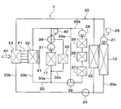
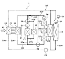
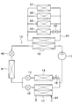
- the refrigeration cycle apparatus 10 includes a compressor 11, a condenser 12, a first expansion valve 80, an outdoor heat exchanger 81, a second expansion valve 13, an air cooling evaporator 14, a constant pressure valve 15, a third expansion valve 16, and cooling.
- This is a vapor compression type refrigerator equipped with a water cooling evaporator 17.
- a fluorocarbon-based refrigerant is used as the refrigerant, and a subcritical refrigeration cycle in which the high-pressure side refrigerant pressure does not exceed the critical pressure of the refrigerant is configured.
- the refrigeration cycle apparatus 10 includes a series refrigerant flow path 10a, a first parallel refrigerant flow path 10b, and a second parallel refrigerant flow path 10c.
- the series refrigerant flow path 10a, the first parallel refrigerant flow path 10b, and the second parallel refrigerant flow path 10c are flow paths through which the refrigerant flows.
- a refrigerant circulation circuit in which the refrigerant circulates is formed by the series refrigerant flow passage 10a, the first parallel refrigerant flow passage 10b, and the second parallel refrigerant flow passage 10c.
- the first parallel refrigerant flow passage 10 b and the second parallel refrigerant flow passage 10 c are connected to the series refrigerant flow passage 10 a so that the refrigerant flows in parallel to each other.
- the compressor 11, the condenser 12, the first expansion valve 80, and the outdoor heat exchanger 81 are arranged in series in this order in the refrigerant flow in the series refrigerant flow path 10a.
- the second expansion valve 13 In the first parallel refrigerant flow passage 10b, the second expansion valve 13, the air cooling evaporator 14 and the constant pressure valve 15 are arranged in series in this order in the flow of the refrigerant.
- the third expansion valve 16 and the cooling water cooling evaporator 17 are arranged in series in this order in the flow of the refrigerant.
- the refrigerant is circulated in the order of the compressor 11, the condenser 12, the second expansion valve 13, the air cooling evaporator 14, the constant pressure valve 15, and the compressor 11 by the series refrigerant flow path 10a and the first parallel refrigerant flow path 10b.
- a circulation circuit is formed.
- a refrigerant circulation circuit in which the refrigerant circulates in the order of the compressor 11, the condenser 12, the third expansion valve 16, and the cooling water cooling evaporator 17 is formed by the series refrigerant flow passage 10a and the second parallel refrigerant flow passage 10c.
- the compressor 11 is an electric compressor driven by electric power supplied from a battery, and sucks, compresses and discharges the refrigerant of the refrigeration cycle apparatus 10.
- the compressor 11 may be a variable displacement compressor driven by a belt.
- the condenser 12 is a high pressure side refrigerant heat medium heat exchanger that condenses the high pressure side refrigerant by heat exchange between the high pressure side refrigerant discharged from the compressor 11 and the cooling water of the high temperature cooling water circuit 20.
- the cooling water of the high temperature cooling water circuit 20 is a fluid as a heat medium.
- the cooling water of the high temperature cooling water circuit 20 is a high temperature heating medium.
- a liquid containing at least ethylene glycol, dimethylpolysiloxane or a nanofluid, or an antifreeze liquid is used as the cooling water of the high temperature cooling water circuit 20.
- the high temperature coolant circuit 20 is a high temperature heat medium circuit in which a high temperature heat medium circulates.
- the first expansion valve 80 is a first pressure reducing portion that reduces and expands the liquid phase refrigerant flowing out of the condenser 12.
- the first expansion valve 80 is an electric variable throttle mechanism, and has a valve body and an electric actuator.
- the valve body is configured to be capable of changing the passage opening degree of the refrigerant passage (in other words, the throttle opening degree).
- the electric actuator has a stepping motor that changes the throttle opening of the valve body.
- the first expansion valve 80 is configured by a variable throttle mechanism with a fully open function that fully opens the refrigerant passage. The operation of the first expansion valve 80 is controlled by a control signal output from the controller 60.
- the outdoor heat exchanger 81 is a refrigerant outside air heat exchanger that exchanges heat between the refrigerant decompressed and expanded by the first expansion valve 80 and the outside air.
- the outdoor heat exchanger 81 When the temperature of the refrigerant flowing through the outdoor heat exchanger 81 is lower than the temperature of the outside air, the outdoor heat exchanger 81 functions as a heat absorber that absorbs the heat of the outside air by the refrigerant. When the temperature of the refrigerant flowing through the outdoor heat exchanger 81 is higher than the temperature of the outside air, the outdoor heat exchanger 81 functions as a radiator that radiates the heat of the refrigerant to the outside air.
- the opening degree of the first expansion valve 80 By controlling the opening degree of the first expansion valve 80, it is possible to switch between the state in which the outdoor heat exchanger 81 functions as a heat absorber and the state in which the outdoor heat exchanger 81 functions as a radiator.
- the outdoor heat exchanger 81 By making the outdoor heat exchanger 81 function as a heat absorber, the heat of the outside air can be used for heating.
- the second expansion valve 13 is a second pressure reducing unit that reduces and expands the liquid phase refrigerant flowing out of the outdoor heat exchanger 81.
- the second expansion valve 13 is an electric variable throttle mechanism, and has a valve body and an electric actuator.
- the valve body is configured to be capable of changing the passage opening degree of the refrigerant passage (in other words, the throttle opening degree).
- the electric actuator has a stepping motor that changes the throttle opening of the valve body.
- the second expansion valve 13 is configured by a variable throttle mechanism with a fully closing function that fully closes the refrigerant passage. That is, the second expansion valve 13 can shut off the flow of the refrigerant by fully closing the refrigerant passage.
- the operation of the second expansion valve 13 is controlled by a control signal output from a controller 60 shown in FIG.
- the air-cooling evaporator 14 is an air-cooling heat exchanger that exchanges heat between the refrigerant flowing out of the second expansion valve 13 and the air blown into the vehicle compartment to cool the air blown into the vehicle compartment.
- the refrigerant absorbs heat from the air blown into the vehicle compartment.
- the constant pressure valve 15 is a pressure adjusting unit (in other words, a pressure adjusting pressure reducing unit) that maintains the pressure of the refrigerant at the outlet side of the air cooling evaporator 14 at a predetermined value.
- the constant pressure valve 15 is configured by a mechanical variable throttle mechanism. Specifically, when the pressure of the refrigerant at the outlet side of the air cooling evaporator 14 falls below a predetermined value, the constant pressure valve 15 reduces the passage area (i.e., the throttle opening degree) of the refrigerant passage, and the air cooling evaporator 14 When the pressure of the refrigerant at the outlet side of the valve exceeds a predetermined value, the passage area (i.e., the throttle opening) of the refrigerant passage is increased.
- the passage area i.e., the throttle opening
- a fixed throttle consisting of an orifice, a capillary tube or the like may be adopted.
- the third expansion valve 16 is a third pressure reducing unit that reduces and expands the liquid phase refrigerant flowing out of the outdoor heat exchanger 81.
- the third expansion valve 16 is an electric variable throttle mechanism, and has a valve body and an electric actuator.
- the valve body is configured to be capable of changing the passage opening degree of the refrigerant passage (in other words, the throttle opening degree).
- the electric actuator has a stepping motor that changes the throttle opening of the valve body.
- the third expansion valve 16 is configured by a variable throttle mechanism with a fully closing function that fully closes the refrigerant passage. That is, the third expansion valve 16 can shut off the flow of the refrigerant by fully closing the refrigerant passage.
- the operation of the third expansion valve 16 is controlled by a control signal output from the controller 60.
- the cooling water cooling evaporator 17 is a low pressure side refrigerant heat medium heat exchanger that evaporates the low pressure refrigerant by heat exchange between the low pressure refrigerant flowing out of the third expansion valve 16 and the cooling water of the low temperature cooling water circuit 30. .
- the gas phase refrigerant evaporated in the cooling water cooling evaporator 17 is drawn into the compressor 11 and compressed.
- the cooling water of the low temperature cooling water circuit 30 is a fluid as a heat medium.
- the cooling water of the low temperature cooling water circuit 30 is a low temperature heating medium.
- a liquid containing at least ethylene glycol, dimethylpolysiloxane or nanofluid, or an antifreeze liquid is used as the cooling water of the low temperature cooling water circuit 30.
- the low temperature coolant circuit 30 is a low temperature heat medium circuit in which a low temperature heat medium circulates.
- a condenser 12 In the high temperature coolant circuit 20, a condenser 12, a high temperature side pump 21, a heater core 22, a high temperature side radiator 23, a two-way valve 24, and a high temperature side reserve tank 25 are disposed.
- the high temperature side pump 21 is a heat medium pump that sucks in and discharges the cooling water.
- the high temperature side pump 21 is an electric pump.
- the high temperature side pump 21 is a high temperature side flow rate adjustment unit that adjusts the flow rate of the cooling water circulating in the high temperature cooling water circuit 20.
- the first low temperature side pump 31 and the second low temperature side pump 34 are low temperature side flow rate adjustment units that adjust the flow rate of the cooling water circulating in the low temperature cooling water circuit 30.
- the heater core 22 is an air heating heat exchanger that heat-exchanges the cooling water of the high-temperature coolant circuit 20 with the air blown into the vehicle compartment to heat the air blown into the vehicle compartment.
- the cooling water dissipates heat to the air blown into the vehicle compartment.
- the condenser 12 and the heater core 22 are air heating units that heat exchange the refrigerant discharged from the compressor 11 and heat the air using the heat of the refrigerant.
- the high temperature side radiator 23 is a high temperature heat medium external air heat exchanger that exchanges heat between the cooling water of the high temperature cooling water circuit 20 and the outside air.
- the condenser 12, the high temperature side pump 21 and the heater core 22 are disposed in the high temperature side circulation flow passage 20a.
- the high temperature side circulation flow passage 20a is a flow passage through which the high temperature side cooling water circulates.
- the high temperature side radiator 23 and the two-way valve 24 are disposed in the radiator flow passage 20b.
- the radiator flow passage 20 b is a flow passage through which the high temperature side cooling water flows in parallel to the heater core 22.
- the two-way valve 24 is a solenoid valve that opens and closes the radiator flow passage 20b. The operation of the two-way valve 24 is controlled by the controller 60.
- the two-way valve 24 is a high temperature switching unit that switches the flow of the cooling water in the high temperature cooling water circuit 20.
- the two-way valve 24 may be a thermostat.
- the thermostat is a cooling water temperature responsive valve provided with a mechanical mechanism that opens and closes the cooling water flow path by displacing the valve body by a thermowax that changes its volume depending on temperature.
- the high temperature side reserve tank 25 is a cooling water storage unit that stores excess cooling water. By storing the excess cooling water in the high temperature side reserve tank 25, it is possible to suppress a decrease in the amount of cooling water circulating in each flow path.
- the high temperature side reserve tank 25 is a closed reserve tank or an open air reserve tank.
- the closed reserve tank is a reserve tank in which the pressure at the liquid surface of the stored cooling water is a predetermined pressure.
- the open air type reserve tank is a reserve tank in which the pressure at the liquid surface of the stored cooling water is atmospheric pressure.
- the low temperature cooling water circuit 30 includes a cooling water cooling evaporator 17, a first low temperature side pump 31, a low temperature side radiator 32, a battery 33, a second low temperature side pump 34, an inverter 35, a charger 36, a motor generator 37, a first A three-way valve 38, a second three-way valve 39, and a low temperature side reserve tank 40 are disposed.
- the first low temperature side pump 31 and the second low temperature side pump 34 are heat medium pumps that suck and discharge the cooling water.
- the first low temperature side pump 31 and the second low temperature side pump 34 are electric pumps.
- the low temperature side radiator 32 is a low temperature heat medium external air heat exchanger that exchanges heat between the cooling water of the low temperature cooling water circuit 30 and the outside air.
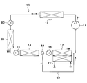
- the high temperature side radiator 23 and the low temperature side radiator 32 are disposed in series in this order in the flow direction A1 of the outside air.
- the high temperature side radiator 23 and the low temperature side radiator 32 are joined together by a common fin F1.
- the common fin F1 is a heat exchange promoting member that promotes the heat exchange between the cooling water and the air.
- the high temperature side radiator 23 and the low temperature side radiator 32 are connected so as to be able to thermally transfer to each other by the common fin F1.
- the outdoor blower 41 shown in FIG. 2 is an outside air blower which blows outside air toward the high temperature side radiator 23, the low temperature side radiator 32, and the outdoor heat exchanger 81.
- the outdoor blower 41 is an electric blower which drives a fan by an electric motor.
- the high temperature side radiator 23, the low temperature side radiator 32, the outdoor heat exchanger 81, and the outdoor blower 41 are disposed at the foremost part of the vehicle. Therefore, when the vehicle travels, traveling air can be applied to the high temperature side radiator 23, the low temperature side radiator 32, and the outdoor heat exchanger 81.
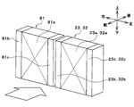
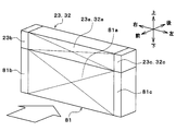
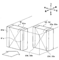
- FIGS. 3 to 5 show examples of the arrangement of the high temperature side radiator 23, the low temperature side radiator 32, and the outdoor heat exchanger 81.
- FIG. 3 to FIG. 5 the up, down, front, back, left, and right arrows indicate the directions of the vehicle.
- the high temperature side radiator 23 and the low temperature side radiator 32 are illustrated integrally.
- the high temperature side radiator 23, the low temperature side radiator 32, and the outdoor heat exchanger 81 are arranged side by side in the vehicle left-right direction.
- the positions of the high-temperature side radiator 23, the low-temperature side radiator 32, and the outdoor heat exchanger 81 in the vertical and longitudinal directions of the vehicle are the same.
- the high temperature side radiator 23, the low temperature side radiator 32, and the outdoor heat exchanger 81 may be arranged side by side in the vehicle vertical direction.
- the high temperature side radiator 23, the low temperature side radiator 32, and the outdoor heat exchanger 81 may be displaced in the longitudinal direction of the vehicle.
- the high temperature side radiator 23, the low temperature side radiator 32, and the outdoor heat exchanger 81 are configured by so-called tank and tube type heat exchangers.
- the outdoor heat exchanger 81 includes an outdoor heat exchange unit 81a and a pair of outdoor tanks 81b and 81c.
- the outdoor heat exchange unit 81 a is a refrigerant outside air heat exchange unit that exchanges heat between the refrigerant and the outside air in the outdoor heat exchanger 81.
- the outdoor heat exchange unit 81a has a plurality of tubes and a plurality of fins.
- the plurality of tubes are refrigerant tubes through which the refrigerant flows.
- the tube is formed of a metal (in the present embodiment, an aluminum alloy) which is excellent in heat conductivity.
- a plurality of tubes are stacked and arranged at regular intervals. Thus, an air passage through which air flows is formed between the adjacent tubes.
- the fins are disposed in an air passage formed between adjacent tubes.
- the fins are heat exchange promoting members that promote heat exchange between the refrigerant and the air.
- the fin is a corrugated fin formed by bending a thin plate made of the same material as the tube into a wave shape.
- the pair of outdoor tanks 81b and 81c are connected to both ends of the plurality of tubes of the outdoor heat exchange section 81a.
- the pair of outdoor tanks 81b and 81c are refrigerant tanks that collect or distribute the refrigerant to a plurality of tubes.
- the outdoor tanks 81b and 81c are formed of the same material as the tube.
- the high temperature side radiator 23 has a high temperature side heat exchange part 23a and a pair of high temperature side tanks 23b and 23c.
- the high temperature side heat exchange unit 23 a is a refrigerant outside air heat exchange unit in the high temperature side radiator 23 that exchanges heat between the cooling water and the air.
- the high temperature side heat exchange unit 23a has a plurality of tubes and a plurality of fins.
- the plurality of tubes are refrigerant tubes for circulating the cooling water.
- the tube is formed of a metal (in the present embodiment, an aluminum alloy) which is excellent in heat conductivity.
- a plurality of tubes are stacked and arranged at regular intervals. Thus, an air passage through which air flows is formed between the adjacent tubes.
- the fins are disposed in an air passage formed between adjacent tubes.
- the fins are heat exchange promoting members that promote heat exchange between the cooling water and the air.
- the fin is a corrugated fin formed by bending a thin plate made of the same material as the tube into a wave shape.
- the pair of high temperature side tanks 23b and 23c are connected to both ends of the plurality of tubes of the high temperature side heat exchange unit 23a.
- the pair of high temperature side tanks 23b and 23c is a refrigerant tank that collects or distributes the refrigerant to a plurality of tubes.
- the high temperature side tanks 23b and 23c are formed of the same material as the tube.
- the low temperature side radiator 32 has a low temperature side heat exchange section 32a and a pair of low temperature side tanks 32b and 32c.
- the low temperature side heat exchange unit 32 a is a low temperature heat medium external air heat exchange unit in the low temperature side radiator 32 that exchanges heat between the cooling water and the air.
- the low temperature side heat exchange unit 32a has a plurality of tubes and a plurality of fins.
- the plurality of tubes are refrigerant tubes for circulating the cooling water.
- the tube is formed of a metal (in the present embodiment, an aluminum alloy) which is excellent in heat conductivity.
- a plurality of tubes are stacked and arranged at regular intervals. Thus, an air passage through which air flows is formed between the adjacent tubes.
- the fins are disposed in an air passage formed between adjacent tubes.
- the fins are heat exchange promoting members that promote heat exchange between the cooling water and the air.
- the fin is a corrugated fin formed by bending a thin plate made of the same material as the tube into a wave shape.
- the pair of low temperature side tanks 32b and 32c are connected to both ends of the plurality of tubes of the low temperature side heat exchange unit 32a.
- the pair of low temperature side tanks 32b and 32c is a refrigerant tank that collects or distributes the refrigerant to a plurality of tubes.
- the low temperature side tanks 32b and 32c are formed of the same material as the tube.
- At least one of the outdoor heat exchange portion 81 a and the low temperature side heat exchange portion 32 a has a portion that does not overlap with the other heat exchange portion in the flow direction of the outside air.
- at least one of the outdoor heat exchange portion 81a and the low temperature side heat exchange portion 32a has a portion that does not overlap with the other heat exchange portion when viewed from the flow direction of the outside air.
- the battery 33, the inverter 35, the charger 36, and the motor generator 37 shown in FIGS. 1 and 2 are in-vehicle devices mounted in a vehicle, and are heat generating devices that generate heat as they operate.
- the battery 33, the inverter 35, the charger 36 and the motor generator 37 dissipate the waste heat generated as the operation is performed to the cooling water of the low temperature cooling water circuit 30.
- the battery 33, the inverter 35, the charger 36 and the motor generator 37 supply heat to the cooling water of the low temperature cooling water circuit 30.
- the inverter 35 is a power conversion unit that converts DC power supplied from the battery 33 into AC power and outputs the AC power to the motor generator 37.
- the charger 36 is a charger for charging the battery 33.
- the motor generator 37 generates driving power for traveling using the electric power output from the inverter 35, and generates regenerative electric power during deceleration or downhill.
- the low temperature side reserve tank 40 is a cooling water storage unit that stores excess cooling water. By storing the excess cooling water in the low temperature side reserve tank 40, it is possible to suppress a decrease in the amount of cooling water circulating in each flow path.
- the low temperature side reserve tank 40 is a closed reserve tank or an open air reserve tank.
- the closed reserve tank is a reserve tank in which the pressure at the liquid surface of the stored cooling water is a predetermined pressure.
- the open air type reserve tank is a reserve tank in which the pressure at the liquid surface of the stored cooling water is atmospheric pressure.
- the first three-way valve 38, the first low temperature side pump 31, the cooling water cooling evaporator 17, and the low temperature side reserve tank 40 are disposed in the low temperature side main flow passage 30a.
- the low temperature side main flow passage 30a is a flow passage through which the low temperature side cooling water flows.
- the low temperature side radiator 32 is disposed in the low temperature side radiator flow passage 30b.
- the low temperature side radiator flow passage 30b is a flow passage through which the low temperature side cooling water flows.
- the low temperature side main flow passage 30a and the low temperature side radiator flow passage 30b form a cooling water circuit in which low temperature side cooling water circulates.
- the battery 33 is disposed in the battery flow passage 30c.
- the battery flow passage 30c is connected to the low temperature side main flow passage 30a.
- the low temperature side main flow passage 30a and the battery flow passage 30c form a cooling water circuit in which the low temperature side cooling water is circulated.
- a first three-way valve 38 is disposed at the connection between the low temperature side main flow passage 30a and the battery flow passage 30c.
- the first three-way valve 38 switches between a state in which the cooling water in the low temperature side main flow path 30 a circulates in the battery flow path 30 c and a state in which the cooling water does not circulate.
- the operation of the first three-way valve 38 is controlled by the controller 60.
- the second low temperature side pump 34, the inverter 35, the charger 36, and the motor generator 37 are disposed in the device flow path 30d.
- the low temperature side main flow passage 30a and the device flow passage 30d form a cooling water circuit in which the low temperature side cooling water circulates.
- a bypass flow passage 30e is connected to the device flow passage 30d.
- the device flow path 30 d and the bypass flow path 30 e form a cooling water circuit in which the low temperature side cooling water circulates.
- a second three-way valve 39 is disposed at the connection between the device flow path 30d and the bypass flow path 30e.
- the second three-way valve 39 switches between a state in which the cooling water in the low temperature side main flow passage 30a circulates in the device flow passage 30d and a state in which the cooling water in the device flow passage 30d circulates in the bypass flow passage 30e. Switch between non-circulating state.
- the operation of the second three-way valve 39 is controlled by the controller 60.
- the first three-way valve 38 and the second three-way valve 39 are low temperature switching units that switch the flow of the cooling water in the low temperature cooling water circuit 30.
- the air cooling evaporator 14 and the heater core 22 are housed in a casing 51 (hereinafter referred to as an air conditioning casing) of the indoor air conditioning unit 50 shown in FIG. 1.
- the indoor air conditioning unit 50 is disposed inside the instrument panel (not shown) at the front of the passenger compartment.
- the air conditioning casing 51 is an air passage forming member that forms an air passage.
- the heater core 22 is disposed on the air flow downstream side of the air cooling evaporator 14 in the air passage in the air conditioning casing 51.
- an inside / outside air switching box 52 and an indoor blower 53 are disposed in the air conditioning casing 51.
- the inside / outside air switching box 52 is an inside / outside air switching unit that switches and introduces inside air and outside air to the air passage in the air conditioning casing 51.
- the indoor blower 53 sucks and blows the inside air and the outside air introduced into the air passage in the air conditioning casing 51 through the inside / outside air switching box 52.
- An air mix door 54 is disposed between the air cooling evaporator 14 and the heater core 22 in the air passage in the air conditioning casing 51.
- the air mix door 54 adjusts the volume ratio of the cold air flowing into the heater core 22 and the cold air flowing through the cold air bypass passage 55 among the cold air having passed through the air cooling evaporator 14.
- the air mix door 54 is an air heating amount adjustment unit that adjusts the heating amount of air in the heater core 22.
- the cold air bypass passage 55 is an air passage through which the cold air that has passed through the air cooling evaporator 14 flows to bypass the heater core 22.
- the air mix door 54 is a rotary door having a rotary shaft rotatably supported on the air conditioning casing 51 and a door base portion coupled to the rotary shaft. By adjusting the position of the air mix door 54, the temperature of the conditioned air blown out from the air conditioning casing 51 into the vehicle compartment can be adjusted to a desired temperature.
- the rotation shaft of the air mix door 54 is driven by a servomotor.
- the operation of the servomotor is controlled by the controller 60.
- the air mix door 54 may be a slide door that slides in a direction substantially orthogonal to the air flow.
- the sliding door may be a plate-like door formed of a rigid body. It may be a film door formed of a flexible film material.
- the conditioned air whose temperature has been adjusted by the air mix door 54 is blown out from the air outlet 56 formed in the air conditioning casing 51 into the vehicle compartment.
- the control device 60 shown in FIG. 6 is composed of a known microcomputer including a CPU, a ROM, a RAM and the like, and peripheral circuits thereof.
- the control device 60 performs various operations and processing based on the control program stored in the ROM.
- Various control target devices are connected to the output side of the control device 60.
- the control device 60 is a control unit that controls the operation of various control target devices.
- the control target devices controlled by the control device 60 include the compressor 11, the first expansion valve 80, the second expansion valve 13, the third expansion valve 16, the outdoor blower 41, the high temperature side pump 21, the two-way valve 24, the first The low temperature side pump 31, the second low temperature side pump 34, the first three-way valve 38, the second three-way valve 39, and the like.
- the software and hardware for controlling the electric motor of the compressor 11 in the control device 60 are a refrigerant discharge capacity control unit.
- the software and hardware which control the 2nd expansion valve 13 among control devices 60 are the 1st iris diaphragm control parts.
- the software and hardware for controlling the third expansion valve 16 in the control device 60 is a second throttle control unit.
- Software and hardware for controlling the outdoor blower 41 in the control device 60 are an outdoor air blowing capacity control unit.
- Software and hardware for controlling the high temperature side pump 21 in the control device 60 is a high temperature heat medium flow rate control unit.
- the software and hardware for controlling the two-way valve 24 in the controller 60 is a two-way valve control unit.
- the software and hardware for controlling the first low temperature side pump 31 and the second low temperature side pump 34 in the control device 60 is a low temperature heat medium flow rate control unit.
- the software and hardware for controlling the first three-way valve 38 in the controller 60 is a first three-way valve control unit.
- Software and hardware for controlling the second three-way valve 39 in the controller 60 is a second three-way valve control unit.
- Various control sensor groups such as a temperature sensor 68 and a window surface humidity sensor 69 are connected.
- the inside air temperature sensor 61 detects a temperature Tr in the passenger compartment.
- the outside air temperature sensor 62 detects the outside air temperature Tam.
- the solar radiation amount sensor 63 detects the solar radiation amount Ts in the vehicle compartment.
- the evaporator temperature sensor 64 is a temperature detection unit that detects the temperature of the cooling water cooling evaporator 17.
- the evaporator temperature sensor 64 is, for example, a fin thermistor that detects the temperature of the heat exchange fin of the cooling water cooling evaporator 17, or a refrigerant temperature sensor that detects the temperature of the refrigerant flowing through the cooling water cooling evaporator 17. .
- the heater core temperature sensor 65 is a temperature detection unit that detects the temperature of the heater core 22.
- the heater core temperature sensor 65 is, for example, a fin thermistor that detects the temperature of heat exchange fins of the heater core 22, a refrigerant temperature sensor that detects the temperature of cooling water flowing through the heater core 22, and air that detects the temperature of air flowing out of the heater core 22. It is a temperature sensor or the like.
- the refrigerant pressure sensor 66 is a refrigerant pressure detection unit that detects the pressure of the refrigerant discharged from the compressor 11. Instead of the refrigerant pressure sensor 66, a refrigerant temperature sensor may be connected to the input side of the control device 60.
- the refrigerant temperature sensor is a refrigerant pressure detection unit that detects the temperature of the refrigerant discharged from the compressor 11.
- the controller 60 may estimate the pressure of the refrigerant based on the temperature of the refrigerant.
- the high temperature coolant temperature sensor 67 is a temperature detection unit that detects the temperature of the coolant in the high temperature coolant circuit 20.
- the high temperature coolant temperature sensor 67 detects the temperature of the coolant of the condenser 12.
- the low temperature coolant temperature sensor 68 is a temperature detection unit that detects the temperature of the coolant in the low temperature coolant circuit 30. For example, the low temperature coolant temperature sensor 68 detects the temperature of the coolant of the coolant cooling evaporator 17.
- the window surface humidity sensor 69 is configured of a near window humidity sensor, a near window air temperature sensor, and a window surface temperature sensor.
- the near-window humidity sensor detects the relative humidity (hereinafter referred to as the near-window relative humidity) of the air in the vehicle room near the windshield in the vehicle room.
- the near-window air temperature sensor detects the temperature of the air in the passenger compartment near the windshield.
- the window surface temperature sensor detects the surface temperature of the windshield.
- Various operation switches (not shown) are connected to the input side of the control device 60.
- Various operation switches are provided on the operation panel 70 and operated by the occupant.
- the operation panel 70 is disposed near the dashboard in the front of the vehicle compartment. Operation signals from various operation switches are input to the control device 60.
- the various operation switches are an air conditioner switch, a temperature setting switch, and the like.
- the air conditioner switch sets whether to cool the air in the indoor air conditioning unit 50 or not.
- the temperature setting switch sets the set temperature of the vehicle interior.
- the control device 60 switches the operation mode to either the cooling mode shown in FIGS. 7 to 8 or the heating mode shown in FIGS. 9 to 10 based on the target blowing temperature TAO or the like.
- the target blowing temperature TAO is a target temperature of the blowing air blown out into the vehicle compartment.
- Control device 60 calculates target blowout temperature TAO based on the following formula.
- TAO Kset ⁇ Tset-Kr ⁇ Tr-Kam ⁇ Tam-Ks ⁇ Ts + C
- Tset is a vehicle interior set temperature set by the temperature setting switch of the operation panel 70
- Tr is the inside air temperature detected by the inside air temperature sensor 61
- Tam is the outside air temperature detected by the outside air temperature sensor 62
- Ts is It is a solar radiation amount detected by the solar radiation amount sensor 63.
- Kset, Kr, Kam, and Ks are control gains
- C is a correction constant.
- the control device 60 switches to the dehumidifying and heating mode when it is determined that the window of the vehicle may become cloudy in the heating mode. For example, in the heating mode, the control device 60 calculates relative humidity RHW (hereinafter referred to as window surface relative humidity) of the vehicle interior side surface based on the detection value of the window surface humidity sensor 69, Based on the relative humidity RHW, it is determined whether the window of the vehicle may become cloudy.
- RHW relative humidity
- the window surface relative humidity RHW is an index that indicates the possibility of the windshield becoming cloudy. Specifically, the larger the value of the window surface relative humidity RHW, the higher the possibility of the windshield being clouded.
- the control device 60 determines operation states (control signals to be output to various control devices) of various control devices connected to the control device 60 based on the target blowout temperature TAO, detection signals of the sensor group, and the like.
- the degree of superheat of the refrigerant flowing into the compressor 11 approaches a target degree of superheat determined in advance so that the coefficient of performance (so-called COP) of the cycle approaches the maximum value. To be determined.
- the air mix door 54 With regard to the control signal output to the servo motor of the air mix door 54, the air mix door 54 is positioned at the solid line position in FIG. 1 to close the air passage of the heater core 22 and of the air passing through the air cooling evaporator 14. The total flow rate is determined to flow around the air passage of the heater core 22.
- the compressor 11 and the high temperature side pump 21 are operated.
- the two-way valve 24 opens the radiator flow passage 20b.
- the cooling water of the high temperature cooling water circuit 20 circulates through the high temperature side radiator 23 and is radiated from the cooling water by the radiator 23 to the outside air.
- the cooling water of the high temperature cooling water circuit 20 also circulates through the heater core 22.
- the air mixing door 54 blocks the air passage of the heater core 22, the heater core 22 hardly dissipates heat from the cooling water to the air. I can not do it.
- the refrigerant flows as indicated by the broken line arrow in FIG. 1, and the state of the refrigerant circulating in the cycle changes as follows.
- the high pressure refrigerant discharged from the compressor 11 flows into the condenser 12.
- the refrigerant flowing into the condenser 12 releases heat to the cooling water of the high temperature cooling water circuit 20.
- the refrigerant is cooled and condensed in the condenser 12.
- the refrigerant flowing out of the condenser 12 flows into the first expansion valve 80. Since the first expansion valve 80 is fully open, the refrigerant is not decompressed and expanded in the first expansion valve 80.
- the refrigerant flowing out of the first expansion valve 80 flows into the outdoor heat exchanger 81, and radiates heat to the outside air. Thereby, the refrigerant is cooled and condensed also in the first expansion valve 80.
- the refrigerant flowing out of the first expansion valve 80 flows into the second expansion valve 13 and is decompressed and expanded in the second expansion valve 13 until it becomes a low pressure refrigerant.
- the low-pressure refrigerant reduced in pressure by the second expansion valve 13 flows into the air cooling evaporator 14, absorbs heat from the air blown into the vehicle compartment, and is evaporated. Thus, the air blown into the vehicle compartment is cooled.
- the low-pressure refrigerant can absorb heat from the air by the air cooling evaporator 14 to blow out the cooled air into the vehicle compartment. Thereby, cooling of the vehicle interior can be realized.
- the third expansion valve 16 is put into a throttled state and the first low temperature side pump 31 is operated.
- the refrigerant flowing out of the condenser 12 flows into the third expansion valve 16 and is decompressed and expanded by the third expansion valve 16 until it becomes a low pressure refrigerant.
- the low pressure refrigerant decompressed by the third expansion valve 16 flows into the cooling water cooling evaporator 17, absorbs heat from the cooling water of the low temperature cooling water circuit 30, and is evaporated. Thereby, the cooling water of the low temperature cooling water circuit 30 is cooled.
- the first three-way valve 38 causes the cooling water in the low temperature side main flow passage 30a to circulate in the battery flow passage 30c.
- the cooling water of the low temperature cooling water circuit 30 circulates in the battery 33 and the battery 33 is cooled.
- the second three-way valve 39 causes the cooling water in the low temperature side main flow passage 30a to circulate in the device flow passage 30d.
- the cooling water of low temperature cooling water circuit 30 circulates through inverter 35, charger 36 and motor generator 37 to cause inverter 35, charger 36 and motor generator 37. Is cooled.
- Heating mode In the heating mode, the controller 60 brings the first expansion valve 80 into the throttling state, brings the second expansion valve 13 into the fully closed state, and brings the third expansion valve 16 into the throttling state.
- the control device 60 determines operation states (control signals to be output to various control devices) of various control devices connected to the control device 60 based on the target blowout temperature TAO, detection signals of the sensor group, and the like.
- the control signal output to the first expansion valve 80 is determined such that the temperature of the refrigerant flowing into the outdoor heat exchanger 81 is equal to or lower than the outside air temperature.
- the control signal output to the third expansion valve 16 is determined so that the degree of superheat of the refrigerant flowing into the compressor 11 approaches a predetermined target degree of superheat.
- the target degree of superheat is set so that the coefficient of performance (so-called COP) of the cycle approaches the maximum value.
- the air mix door 54 With regard to the control signal output to the servo motor of the air mix door 54, the air mix door 54 is located at the broken line position in FIG. 1 to fully open the air passage of the heater core 22 and of the air passing through the air cooling evaporator 14. The total flow rate is determined to pass through the air passage of the heater core 22.
- the compressor 11, the high temperature side pump 21, and the first low temperature side pump 31 are operated.
- the two-way valve 24 closes the radiator flow passage 20b.
- the coolant of high temperature coolant circuit 20 circulates through heater core 22 and is dissipated from the coolant by heater core 22 into the air blown into the vehicle compartment. Be done.
- the first three-way valve 38 closes the battery flow passage 30c
- the second three-way valve 39 closes the device flow passage 30d and the bypass flow passage 30e.
- the cooling water of the low temperature cooling water circuit 30 circulates through the low temperature side radiator 32.
- the refrigerant flows as indicated by solid arrows in FIG. 1, and the state of the refrigerant circulating in the cycle changes as follows.
- the high pressure refrigerant discharged from the compressor 11 flows into the condenser 12, exchanges heat with the cooling water of the high temperature cooling water circuit 20, and radiates heat. Thereby, the cooling water of the high temperature cooling water circuit 20 is heated.
- the refrigerant flowing out of the condenser 12 flows into the first expansion valve 80 and is depressurized so as to be equal to or lower than the outside air temperature. Then, the refrigerant decompressed by the first expansion valve 80 flows into the outdoor heat exchanger 81 and hardly exchanges heat with the outside air or absorbs heat from the outside air.
- the refrigerant flowing out of the first expansion valve 80 flows into the third expansion valve 16 and is decompressed until it becomes a low pressure refrigerant. Then, the low pressure refrigerant decompressed by the third expansion valve 16 flows into the cooling water cooling evaporator 17, absorbs heat from the cooling water of the low temperature cooling water circuit 30, and evaporates.
- the heat of the high pressure refrigerant discharged from the compressor 11 is dissipated to the cooling water of the high temperature cooling water circuit 20 by the condenser 12 and the heat of the cooling water of the high temperature cooling water circuit 20 is The heat can be released to the air by the heater core 22 and the air heated by the heater core 22 can be blown out into the vehicle interior. Thereby, heating of the vehicle interior can be realized.
- the cooling water of the low temperature cooling water circuit 30 circulates through the low temperature side radiator 32, heat is absorbed from the outside air into the cooling water of the low temperature cooling water circuit 30, and the cooling water of the low temperature cooling water circuit 30 is used in the cooling water cooling evaporator 17.
- the low pressure refrigerant can absorb heat. Therefore, the heat of the outside air can be used to heat the vehicle interior.
- the cooling water of the low temperature cooling water circuit 30 is also circulated to the battery 33, the inverter 35, the charger 36 and the motor generator 37. Absorbing waste heat of the inverter 35, the charger 36 and the motor generator 37 into the cooling water of the low temperature cooling water circuit 30, and absorbing heat from the cooling water of the low temperature cooling water circuit 30 into the low pressure refrigerant in the cooling water cooling evaporator 17. Can.
- waste heat of battery 33, inverter 35, charger 36 and motor generator 37 can be used to heat the vehicle interior. Further, waste heat of the battery 33, the inverter 35, the charger 36 and the motor generator 37 can be used for defrosting of the low temperature side radiator 32.
- Waste heat can be used to heat and defrost the vehicle interior.
- the high temperature side radiator 23 and the low temperature side radiator 32 are connected so as to be able to transfer heat to each other by the common fin F1, the heat of the cooling water of the high temperature cooling water circuit 20 is transmitted from the high temperature side radiator 23 to the low temperature side radiator 32.
- the temperature of the low temperature side radiator 32 is increased, and the frost adhering to the surface of the low temperature side radiator 32 can be melted.
- the control device 60 sets the first expansion valve 80 in the squeezed state, sets the second expansion valve 13 in the fully closed state, and sets the third expansion valve 16 in the fully closed state.
- the control device 60 determines operation states (control signals to be output to various control devices) of various control devices connected to the control device 60 based on the target blowout temperature TAO, detection signals of the sensor group, and the like.
- the control signal output to the first expansion valve 80 is determined such that the temperature of the refrigerant flowing into the outdoor heat exchanger 81 is lower than the outside air temperature.
- the control signal output to the third expansion valve 16 is determined so that the degree of superheat of the refrigerant flowing into the third expansion valve 16 approaches a predetermined target degree of superheat.
- the target degree of superheat is set so that the coefficient of performance (so-called COP) of the cycle approaches the maximum value.
- the air mix door 54 With regard to the control signal output to the servo motor of the air mix door 54, the air mix door 54 fully opens the air passage of the heater core 22, and the total flow rate of air passing through the air cooling evaporator 14 is the air passage of the heater core 22. It is decided to pass.
- the compressor 11, the high temperature side pump 21, and the first low temperature side pump 31 are operated.
- the two-way valve 24 closes the radiator flow passage 20b.
- the coolant of high temperature coolant circuit 20 circulates through heater core 22 and is dissipated from the coolant by heater core 22 into the air blown into the vehicle compartment. Be done.
- the refrigerant flows as indicated by the broken line arrow in FIG. 1, and the state of the refrigerant circulating in the cycle changes as follows.
- the high pressure refrigerant discharged from the compressor 11 flows into the condenser 12, exchanges heat with the cooling water of the high temperature cooling water circuit 20, and radiates heat. Thereby, the cooling water of the high temperature cooling water circuit 20 is heated.
- the refrigerant flowing out of the condenser 12 flows into the first expansion valve 80 and is depressurized so as to be lower than the outside air temperature. Then, the refrigerant decompressed by the first expansion valve 80 flows into the outdoor heat exchanger 81 and absorbs heat from the outside air.
- the refrigerant flowing out of the first expansion valve 80 flows into the second expansion valve 13 and is decompressed until it becomes a low pressure refrigerant. Then, the low pressure refrigerant reduced in pressure by the second expansion valve 13 flows into the air cooling evaporator 14 and absorbs heat from the air blown into the vehicle compartment to evaporate. Thus, the air blown into the vehicle compartment is cooled and dehumidified. Then, the refrigerant flowing out of the air cooling evaporator 14 flows to the suction side of the compressor 11 and is compressed again by the compressor 11.
- the heat of the high pressure refrigerant discharged from the compressor 11 is dissipated to the cooling water of the high temperature cooling water circuit 20 by the condenser 12 and the heat of the cooling water of the high temperature cooling water circuit 20 The heat is released to the air by the heater core 22.
- the low pressure refrigerant decompressed by the third expansion valve 16 is absorbed from the air blown into the vehicle compartment by the air cooling evaporator 14, and the air cooled and dehumidified by the air cooling evaporator 14 is a heater core. It can heat at 22 and can blow out to a vehicle interior. Thereby, dehumidification heating of a vehicle interior can be realized.
- the refrigerant expanded in pressure by the first expansion valve 80 flows into the outdoor heat exchanger 81 to absorb heat from the outside air by setting the first expansion valve 80 in the squeezed state. Therefore, the heat of the outside air can be used to heat the vehicle interior.
- the low pressure refrigerant reduced in pressure by the third expansion valve 16 flows into the cooling water cooling evaporator 17 by bringing the third expansion valve 16 into a throttling state, and cooling of the low temperature cooling water circuit 30 It absorbs heat from water and evaporates.
- the cooling water of the low temperature cooling water circuit 30 is circulated in the low temperature side radiator 32 to absorb heat from the outside air to the cooling water of the low temperature cooling water circuit 30.
- the low-pressure refrigerant can absorb heat from the cooling water of the low-temperature cooling water circuit 30 in the cooling water cooling evaporator 17. Therefore, the heat of the outside air can be used to heat the vehicle interior.
- the cooling water cooled by the cooling water cooling evaporator 17 is also circulated to the battery 33, the inverter 35, the charger 36 and the motor generator 37.
- the waste heat of the battery 33, the inverter 35, the charger 36 and the motor generator 37 is absorbed by the cooling water of the low temperature cooling water circuit 30, and the cooling water of the low temperature cooling water circuit 30 is changed to a low pressure refrigerant in the cooling water cooling evaporator 17. It can be absorbed heat. Therefore, the waste heat of battery 33, inverter 35, charger 36 and motor generator 37 can be used to heat the vehicle interior.
- the refrigerant flow to the evaporator 14 for air cooling and the evaporator 17 for thermal cooling water cooling, and the cooling water flow in the high temperature cooling water circuit 20 and the low temperature cooling water circuit 30
- proper cooling, heating and dehumidifying heating can be performed in the vehicle interior, and thus comfortable air conditioning of the vehicle interior can be realized.
- the controller 60 controls the second three-way valve 39 so that the cooling water of the low temperature cooling water circuit 30 circulates between the low temperature side radiator 32 and the inverter 35, the charger 36 and the motor generator 37 as shown in FIG.
- the waste heat of inverter 35, charger 36 and motor generator 37 can be released to the outside air to cool inverter 35, charger 36 and motor generator 37.
- the first expansion valve 80 can be switched between a state in which the refrigerant dissipates heat to the outside air by the outdoor heat exchanger 81 and a state in which the refrigerant absorbs heat from the outside air by the outdoor heat exchanger 81. Then, when the air is cooled by the air cooling evaporator 14 and the air is heated by the heater core 22, the third expansion valve 16 causes the coolant to flow to the cooling water cooling evaporator 17.
- the refrigerant cools the air in the air cooling evaporator 14 and the refrigerant dissipates the outside air in the outdoor heat exchanger 81, whereby the cooling mode can be realized.
- the refrigerant absorbs heat from the outside air in the outdoor heat exchanger 81, and the heat of the refrigerant is used in the condenser 12 and the heater core 22 to heat the air, whereby the heating mode can be realized.
- the refrigerant cools the air in the air cooling evaporator 14 and heats the air in the condenser 12 and the heater core 22 using the heat of the refrigerant to realize the dehumidifying and heating mode.
- the cooling water cooling evaporator 17 can absorb the heat from the heat medium. Therefore, since it is not necessary to frequently switch the high and low pressure of the outdoor heat exchanger 81 at the time of the dehumidifying and heating mode, the operation and control can be simplified.
- the first expansion valve 80 can be switched between a state in which the refrigerant dissipates heat to the outside air by the outdoor heat exchanger 81 and a state in which the refrigerant absorbs heat from the outside air by the outdoor heat exchanger 81.
- the outdoor heat exchanger 81 has an outdoor heat exchange unit 81a that exchanges heat between the refrigerant and the outside air.
- the low temperature side radiator 32 has a low temperature side heat exchange section 32 a that exchanges heat between the cooling water and the outside air.
- At least one heat exchange portion of the outdoor heat exchange portion 81a and the low temperature side heat exchange portion 32a has a portion that does not overlap in the flow direction of the other heat exchange portion and the outside air.
- the third expansion valve 16 causes the refrigerant to flow to the cooling water cooling evaporator 17 when the refrigerant absorbs heat from the outside air in the outdoor heat exchanger 81 and the air is heated in the heater core 22.
- the refrigerant cools the air in the air cooling evaporator 14 and the refrigerant dissipates the outside air in the outdoor heat exchanger 81, whereby the cooling mode can be realized.
- the refrigerant absorbs heat from the outside air in the outdoor heat exchanger 81, and the heat of the refrigerant is used in the condenser 12 and the heater core 22 to heat the air, whereby the heating mode can be realized.
- the cooling water cooling evaporator 17 can absorb heat from the cooling water.
- At least one of the outdoor heat exchange portion 81a and the low temperature side heat exchange portion 32a has a portion that does not overlap in the flow direction of the other heat exchange portion and the outside air, so the outdoor heat exchange portion 81a
- the heat absorption area can be increased by increasing the heat exchange area of the low temperature side heat exchange section 32a. Therefore, the heating performance can be improved.
- the cooling water cooled by the cooling water cooling evaporator 17 circulates through the low temperature cooling water circuit 30, the cooling water of the low temperature cooling water circuit 30 is the heat of the outside air also in the piping portion of the low temperature cooling water circuit 30 and the like. Can absorb heat.
- the compressor 11 when the air is cooled by the air cooling evaporator 14 and the air is heated by the heater core 22, the compressor 11, the heater core 22, the first expansion valve 80, the outdoor heat exchanger 81, the second expansion
- the refrigerant circulates in the order of the valve 13, the evaporator 14 for air cooling, and the compressor 11.
- the refrigerant cools the air in the air cooling evaporator 14, and the heat of the refrigerant is used in the condenser 12 and the heater core 22 to heat the air, whereby dehumidifying and heating can be realized.
- the air cooling evaporator 14 and the cooling water cooling evaporator 17 are arranged in parallel with each other in the flow of the refrigerant. Thereby, the temperature zone of the evaporator 14 for air cooling and the evaporator 17 for cooling water cooling can be adjusted easily.
- the pressure adjustment unit 25 makes the outlet-side refrigerant pressure of the air-cooling evaporator 14 equal to or higher than the outlet-side refrigerant pressure of the coolant-cooling evaporator 17.
- dehumidifying and heating can be performed in a wide temperature range in the low outside air temperature zone.
- the second expansion valve 13 and the second expansion valve 15 are electrically variable throttle mechanisms with a fully closed function, but in the present embodiment, as shown in FIG.
- the second expansion valve 15 is a mechanical thermal expansion valve
- the first on-off valve 18 is disposed in the first parallel refrigerant flow passage 10b
- the second on-off valve 19 is disposed in the second parallel refrigerant flow passage 10c. ing.
- the mechanical expansion valve is a thermal expansion valve that has a temperature sensing unit and drives a valve body by a mechanical mechanism such as a diaphragm.
- the first on-off valve 18 is an electromagnetic valve that opens and closes the first parallel refrigerant flow passage 10 b.
- the second on-off valve 19 is an electromagnetic valve that opens and closes the second parallel refrigerant flow passage 10c. The operation of the first on-off valve 18 and the second on-off valve 19 is controlled by a control signal output from the controller 60.
- the constant pressure valve 15 is a mechanical variable throttle mechanism, but in the present embodiment, it is an electric variable throttle mechanism, and the operation of the constant pressure valve 15 is controlled from the control device 60 Controlled by the signal.
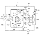
- the high temperature side radiator 23 and the low temperature side radiator 32 are connected so as to be able to transfer heat to each other by the common fin F1, but in the present embodiment, as shown in FIG.
- the side radiators 32 are capable of heat transfer to each other via the cooling water.
- the radiator flow passage 20 b and the low temperature side radiator flow passage 30 b are in communication by two cooling water flow passages 45 and 46.
- the two cooling water flow paths 45, 46 connect the high temperature side radiator 23 and the low temperature side radiator 32 on the inlet side and the outlet side of the cooling water.
- An on-off valve 47 is disposed in one cooling water flow path 45.
- An open / close valve 48 is disposed in the other cooling water passage 46.
- One on-off valve 47 is an electromagnetic valve that opens and closes one cooling water passage 45.
- the other on-off valve 48 is a solenoid valve that opens and closes the other cooling water passage 46. The operation of the on-off valves 47 and 48 is controlled by the controller 60.
- the controller 60 controls the on-off valves 47 and 48 to close the cooling water channels 45 and 46 under normal conditions.
- the control device 60 controls the on-off valves 47 and 48 to open the cooling water channels 45 and 46 when the vehicle stops after the heating mode is performed. Thereby, the cooling water of the high temperature cooling water circuit 20 is introduced to the low temperature side radiator 32, so the temperature of the low temperature side radiator 32 is raised by utilizing the heat remaining in the cooling water of the high temperature cooling water circuit 20. The frost adhering to the surface of the side radiator 32 can be melted.
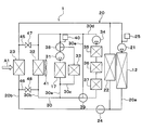
- an engine 26 and an engine radiator 27 are disposed in the high temperature coolant circuit 20.
- the engine radiator 27 is a heat exchanger for radiating heat which exchanges heat between the high temperature cooling water after cooling the engine 26 and the outside air to radiate the heat from the cooling water of the high temperature cooling water circuit 20 to the outside air.
- the heater core 22, the high temperature side radiator 23, the engine 26, and the engine radiator 27 are arranged in parallel to each other in the flow of the cooling water of the high temperature cooling water circuit 20.
- waste heat of the engine 26 can be used for heating.
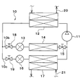
- an indoor condenser 82 is disposed instead of the condenser 12 and the heater core 22 of the above embodiment.
- the indoor condenser 82 is disposed in the refrigeration cycle apparatus 10 instead of the condenser 12 of the above embodiment. Specifically, the indoor condenser 82 condenses the high-pressure side refrigerant by exchanging heat between the high-pressure side refrigerant discharged from the compressor 11 and the air blown into the vehicle interior, and the air blown into the vehicle interior Is an air heating unit that heats
- the indoor condenser 82 is disposed in the air passage in the air conditioning casing 51 in place of the heater core 22 of the above embodiment. Specifically, the indoor condenser 82 is disposed on the air flow downstream side of the air cooling evaporator 14 in the air passage in the air conditioning casing 51.
- the air cooling evaporator 14 and the cooling water cooling evaporator 17 are arranged in parallel with each other in the refrigerant flow, but in the present embodiment, as shown in FIG. 14 and cooling water cooling evaporators 17 are arranged in series with each other in the refrigerant flow.
- the second expansion valve 13, the air cooling evaporator 14, the third expansion valve 16, and the cooling water cooling evaporator 17 are arranged in this order.
- the refrigeration cycle apparatus 10 has a bypass flow passage 83 and a bypass three-way valve 84.
- the bypass flow path 83 is a refrigerant flow path in which the refrigerant flows by bypassing the third expansion valve 16 and the cooling water cooling evaporator 17.
- the bypass three-way valve 84 bypasses the third expansion valve 16 and the cooling water cooling evaporator 17 when the refrigerant flowing out of the air cooling evaporator 14 flows through the third expansion valve 16 and the cooling water cooling evaporator 17. It is an electromagnetic valve that switches between the flow in the bypass passage 83 and the flow in the bypass flow passage 83. The operation of the bypass three-way valve 84 is controlled by the controller 60.
- the control device 60 In the cooling mode, the control device 60 causes the first expansion valve 80 to be fully open, the second expansion valve 13 to be in the throttling state, and the bypass three-way valve 84 to be in the state where the refrigerant flows in the bypass flow path 83.
- the control device 60 determines operation states (control signals to be output to various control devices) of various control devices connected to the control device 60 based on the target blowout temperature TAO, detection signals of the sensor group, and the like.
- the degree of superheat of the refrigerant flowing into the compressor 11 approaches a target degree of superheat determined in advance so that the coefficient of performance (so-called COP) of the cycle approaches the maximum value. To be determined.
- the air mix door 54 With regard to the control signal output to the servo motor of the air mix door 54, the air mix door 54 is located at the solid line position of FIG. 1 and blocks the air passage of the indoor condenser 82 and passes through the air cooling evaporator 14. The total flow rate of air is determined to flow around the air passage of the indoor condenser 82.
- the compressor 11 In the cooling mode, the compressor 11 is operated. In the refrigeration cycle apparatus 10 in the cooling mode, the refrigerant flows as indicated by the broken line arrow in FIG. 13, and the state of the refrigerant circulating in the cycle changes as follows.
- the high pressure refrigerant discharged from the compressor 11 flows into the indoor condenser 82.
- the indoor condenser 82 since the air mix door 54 blocks the air passage of the indoor condenser 82, the indoor condenser 82 hardly dissipates heat from the high pressure refrigerant to the air.
- the refrigerant flowing out of the condenser 12 flows into the first expansion valve 80. Since the first expansion valve 80 is fully open, the refrigerant is not decompressed and expanded in the first expansion valve 80.
- the refrigerant flowing out of the first expansion valve 80 flows into the outdoor heat exchanger 81, and radiates heat to the outside air. Thus, the refrigerant is cooled and condensed by the first expansion valve 80.
- the refrigerant flowing out of the first expansion valve 80 flows into the second expansion valve 13 and is decompressed and expanded in the second expansion valve 13 until it becomes a low pressure refrigerant.
- the low-pressure refrigerant reduced in pressure by the second expansion valve 13 flows into the air cooling evaporator 14, absorbs heat from the air blown into the vehicle compartment, and is evaporated. Thus, the air blown into the vehicle compartment is cooled.
- the refrigerant flowing out of the air cooling evaporator 14 passes through the bypass flow passage 83, flows to the suction side of the compressor 11, and is compressed again by the compressor 11.
- the low-pressure refrigerant can absorb heat from the air by the air cooling evaporator 14 to blow out the cooled air into the vehicle compartment. Thereby, cooling of the vehicle interior can be realized.
- the control device 60 sets the first expansion valve 80 in the squeezed state, sets the second expansion valve 13 in the squeezed state, the bypass three-way valve 84, and the refrigerant is the third expansion valve 16 and the cooling water cooling evaporator Let 17 flow.
- the third expansion valve 16 is fully closed.
- the control device 60 determines operation states (control signals to be output to various control devices) of various control devices connected to the control device 60 based on the target blowout temperature TAO, detection signals of the sensor group, and the like.
- the control signal output to the first expansion valve 80 is determined such that the temperature of the refrigerant flowing into the outdoor heat exchanger 81 is lower than the outside air temperature.
- the control signal output to the second expansion valve 13 is determined so that the degree of superheat of the refrigerant flowing into the compressor 11 approaches a predetermined target degree of superheat.
- the target degree of superheat is set so that the coefficient of performance (so-called COP) of the cycle approaches the maximum value.
- the air mix door 54 As for the control signal output to the servo motor of the air mix door 54, the air mix door 54 fully opens the air passage of the indoor condenser 82, and the total flow rate of the air passing through the air cooling evaporator 14 is the indoor condenser 82. It is decided to pass through the air passage of the
- the compressor 11 and the first low temperature side pump 31 are operated.
- the refrigerant flows as indicated by solid arrows in FIG. 13, and the state of the refrigerant circulating in the cycle changes as follows.
- the high-pressure refrigerant discharged from the compressor 11 flows into the indoor condenser 82, exchanges heat with the air blown into the vehicle compartment, and radiates heat.
- the air blown into the vehicle compartment is heated.
- the refrigerant flowing out of the indoor condenser 82 flows into the first expansion valve 80 and is depressurized so as to be less than the outside air temperature. Then, the refrigerant decompressed by the first expansion valve 80 flows into the outdoor heat exchanger 81 and absorbs heat from the outside air.
- the refrigerant flowing out of the first expansion valve 80 flows into the second expansion valve 13 and is decompressed until it becomes a low pressure refrigerant. Then, the low pressure refrigerant reduced in pressure by the second expansion valve 13 flows into the air cooling evaporator 14 and absorbs heat from the air blown into the vehicle compartment to evaporate. Thus, the air blown into the vehicle compartment is cooled and dehumidified. Then, the refrigerant flowing out of the air cooling evaporator 14 flows into the third expansion valve 16, and the refrigerant flowing out of the third expansion valve 16 flows into the cooling water cooling evaporator 17, and the low temperature cooling water circuit 30 Absorbs heat from the cooling water and evaporates. The refrigerant flowing out of the cooling water cooling evaporator 17 flows to the suction side of the compressor 11 and is compressed by the compressor 11 again.
- the heat of the high-pressure refrigerant discharged from the compressor 11 is released to the air by the indoor condenser 82.
- the low pressure refrigerant decompressed by the third expansion valve 16 is absorbed from the air blown into the vehicle compartment by the air cooling evaporator 14, and the air cooled and dehumidified by the air cooling evaporator 14 is a heater core. It can heat at 22 and can blow out to a vehicle interior. Thereby, dehumidification heating of a vehicle interior can be realized.
- the refrigerant expanded in pressure by the first expansion valve 80 flows into the outdoor heat exchanger 81 to absorb heat from the outside air by setting the first expansion valve 80 in the squeezed state. Therefore, the heat of the outside air can be used to heat the vehicle interior.
- the low pressure refrigerant flows into the cooling water cooling evaporator 17, absorbs heat from the cooling water of the low temperature cooling water circuit 30, and evaporates.
- the cooling water of the low temperature cooling water circuit 30 is circulated to the low temperature side radiator 32 to absorb heat from the outside air to the cooling water of the low temperature cooling water circuit 30, and the cooling water cooling evaporator 17 of the low temperature cooling water circuit 30 It is possible to absorb heat from the cooling water to the low pressure refrigerant. Therefore, the heat of the outside air can be used to heat the vehicle interior.
- the heater core 22 is disposed in the high temperature coolant circuit 20.
- various in-vehicle devices may be disposed instead of the heater core 22.
- cooling water is used as a heat carrier
- various media such as oil, may be used as a heat carrier.
- Nano fluid may be used as a heat carrier.
- the nanofluid is a fluid in which nanoparticles having a particle size of nanometer order are mixed.
- the following effects can be obtained by mixing the nanoparticles in the heat medium.
- the effect of improving the thermal conductivity in a specific temperature zone the effect of increasing the heat capacity of the heat medium, the effect of preventing corrosion of metal piping and the deterioration of rubber piping, and the heat medium at extremely low temperature
- Such effects vary depending on the particle configuration of the nanoparticles, the particle shape, the blending ratio, and the additive substance.
- the thermal conductivity can be improved, it is possible to obtain the same cooling efficiency even with a small amount of heat medium as compared with the cooling water using ethylene glycol.
- the heat capacity of the heat medium can be increased, the amount of stored heat due to the sensible heat of the heat medium itself can be increased.
- the aspect ratio of the nanoparticles is preferably 50 or more. It is because sufficient thermal conductivity can be obtained.
- the aspect ratio is a shape index that represents the ratio of length x width of the nanoparticles.
- nanoparticles those containing any of Au, Ag, Cu and C can be used. Specifically, Au nanoparticles, Ag nanowires, CNTs, graphene, graphite core-shell nanoparticles, Au nanoparticle-containing CNTs, and the like can be used as constituent atoms of the nanoparticles.
- CNTs are carbon nanotubes.
- the graphite core-shell type nanoparticles are particles in which a structure such as a carbon nanotube is present so as to surround the atoms.
- a fluorocarbon refrigerant is used as the refrigerant, but the type of refrigerant is not limited to this, and a natural refrigerant such as carbon dioxide, a hydrocarbon refrigerant, etc. You may use.
- the refrigeration cycle apparatus 10 of the above embodiment constitutes a subcritical refrigeration cycle in which the high pressure side refrigerant pressure does not exceed the critical pressure of the refrigerant, but a supercritical refrigeration cycle in which the high pressure side refrigerant pressure exceeds the critical pressure of the refrigerant May be configured.
- the high temperature side radiator 23 and the low temperature side radiator 32 are separate radiators, and the high temperature side radiator 23 and the low temperature side radiator 32 are mutually joined by the common fin F1.
- the high temperature side radiator 23 and the low temperature side radiator 32 may be configured by one radiator.
- the high temperature side radiator 23 and the low temperature side radiator 32 may be configured by one radiator.
- an intermediate pressure refrigerant or high pressure refrigerant may flow to the air cooling evaporator 14. That is, the opening degree of the first expansion valve 80 and the second expansion valve 13 may be adjusted so that the intermediate pressure refrigerant or the high pressure refrigerant flows into the air cooling evaporator 14.
Abstract
空調装置は、熱媒体と外気とを熱交換させる低温熱媒体外気熱交換器(32)と、低圧側冷媒熱媒体熱交換器(17)と発熱機器(33、35、36、37)と熱媒体外気熱交換器(32)とに熱媒体を循環させる熱媒体回路(30)とを備える。 第1減圧部(80)は、冷媒外気熱交換器(81)で冷媒が外気に放熱する状態と、冷媒外気熱交換器(81)で冷媒が外気から吸熱する状態とを切り替え可能になっており、冷媒流れ切替部(16、84)は、空気冷却用熱交換器(14)で空気が冷却され且つ空気加熱部(12、22)で空気が加熱されている場合、低圧側冷媒熱媒体熱交換器(17)に冷媒が流れる状態にする。
Description
本出願は、当該開示内容が参照によって本出願に組み込まれた、2017年8月10日に出願された日本特許出願2017-155681号を基にしている。
本開示は、冷房と暖房を行うことのできる空調装置に関する。
従来、特許文献1には、冷凍サイクルを有する空調装置が記載されている。この冷凍サイクル装置では、冷房モードと暖房モードとで冷媒回路を切り替え、冷房モード時には室外熱交換器を放熱器として機能させ、暖房モード時には室外熱交換器を蒸発器と機能させる。
すなわち、室外熱交換器のモリエル線図上の位置を、冷房モード時には高圧にし、暖房モード時には低圧にする。
さらに、この従来技術では、除湿暖房モード時には、目標吹出温度に応じて、室外熱交換器を放熱器と機能させたり蒸発器として機能させたりする。すなわち、除湿暖房モード時には、室外熱交換器のモリエル線図上の位置を高圧にしたり低圧にしたりする。
このように、運転モードに応じて室外熱交換器の高低圧を切り替える構成では、冷媒回路に圧力調整弁や切替弁が必要となるため、回路や制御が複雑になりやすい。
特に、除湿暖房モードにおいては、室外熱交換器の高低圧を頻繁に切り替える必要があるとともに、室外熱交換器における吸熱量や放熱量を連続的に制御しなければならないことから、作動や制御が非常に複雑になってしまうことがある。
また、上記従来技術では、暖房モード時には室外熱交換器を蒸発器と機能させるが、室外熱交換器の吸熱能力が不足して暖房能力不足になりやすい。
本開示は、暖房モード、冷房モードおよび除湿暖房モードを切り替え可能な空調装置の構成を簡素化することを目的とする。
また、本開示は、暖房モード、冷房モードおよび除湿暖房モードを切り替え可能な空調装置の暖房能力を向上することを他の目的とする。
本開示の一つの特徴例による空調装置は、
冷媒を吸入して圧縮して吐出する圧縮機と、
圧縮機から吐出された冷媒を熱交換させ、冷媒の熱を利用して、空調対象空間へ送風される空気を加熱する空気加熱部と、
空気加熱部における空気の加熱量を調整する空気加熱量調整部と、
空気加熱部の冷媒出口側かつ圧縮機の冷媒吸入側に配置され、冷媒を減圧させる第1減圧部と、
第1減圧部から流出した冷媒と外気とを熱交換させる冷媒外気熱交換器と、
冷媒外気熱交換器で熱交換された冷媒を減圧させる第2減圧部と、
第2減圧部から流出した冷媒と、空気加熱部で加熱される前の空気とを熱交換させて空気を冷却する空気冷却用熱交換器と、
冷媒外気熱交換器または空気冷却用熱交換器で熱交換された冷媒を減圧させる第3減圧部と、
第3減圧部から流出した冷媒と熱媒体とを熱交換させる低圧側冷媒熱媒体熱交換器と、
低圧側冷媒熱媒体熱交換器に対して、冷媒が流れる状態と流れない状態とを切り替える冷媒流れ切替部と、
作動に伴って発熱し、熱媒体によって冷却される発熱機器と、
熱媒体と外気とを熱交換させる低温熱媒体外気熱交換器と、
低圧側冷媒熱媒体熱交換器と発熱機器と熱媒体外気熱交換器とに熱媒体を循環させる熱媒体回路とを備える。
第1減圧部は、冷媒外気熱交換器で冷媒が外気に放熱する状態と、冷媒外気熱交換器で冷媒が外気から吸熱する状態とを切り替え可能になっており、
冷媒流れ切替部は、空気冷却用熱交換器で空気が冷却され且つ空気加熱部で空気が加熱されている場合、低圧側冷媒熱媒体熱交換器に冷媒が流れる状態にする。
これによると、空気冷却用熱交換器にて冷媒が空気を冷却し、冷媒外気熱交換器にて冷媒が外気に放熱することによって冷房モードを実現できる。
冷媒外気熱交換器にて冷媒が外気から吸熱し、空気加熱部にて冷媒の熱を利用して空気を加熱することによって暖房モードを実現できる。
そして、空気冷却用熱交換器にて冷媒が空気を冷却し、空気加熱部にて冷媒の熱を利用して空気を加熱することによって除湿暖房モードを実現できる。
除湿暖房モードでは、低圧側冷媒熱媒体熱交換器に冷媒が流れる状態にするので、低圧側冷媒熱媒体熱交換器にて冷媒が熱媒体から吸熱できる。そのため、除湿暖房モード時に冷媒外気熱交換器の高低圧を頻繁に切り替える必要が無いので、作動や制御を簡素化できる。
本開示のもう一つの特徴例による空調装置は、
冷媒を吸入して圧縮して吐出する圧縮機と、
圧縮機から吐出された冷媒を熱交換させ、冷媒の熱を利用して、空調対象空間へ送風される空気を加熱する空気加熱部と、
空気加熱部における空気の加熱量を調整する空気加熱量調整部と、
空気加熱部の冷媒出口側かつ圧縮機の冷媒吸入側に配置され、冷媒を減圧させる第1減圧部と、
第1減圧部から流出した冷媒と外気とを熱交換させる冷媒外気熱交換器と、
冷媒外気熱交換器で熱交換された冷媒を減圧させる第2減圧部と、
第2減圧部から流出した冷媒と、空気加熱部で加熱される前の空気とを熱交換させて空気を冷却する空気冷却用熱交換器と、
冷媒外気熱交換器または空気冷却用熱交換器で熱交換された冷媒を減圧させる第3減圧部と、
第3減圧部から流出した冷媒と熱媒体とを熱交換させる低圧側冷媒熱媒体熱交換器と、
低圧側冷媒熱媒体熱交換器に対して、冷媒が流れる状態と流れない状態とを切り替える冷媒流れ切替部と、
作動に伴って発熱し、熱媒体によって冷却される発熱機器と、
熱媒体と外気とを熱交換させる低温熱媒体外気熱交換器と、
低圧側冷媒熱媒体熱交換器と発熱機器と熱媒体外気熱交換器とに熱媒体を循環させる熱媒体回路とを備える。
第1減圧部は、冷媒外気熱交換器で冷媒が外気に放熱する状態と、冷媒外気熱交換器で冷媒が外気から吸熱する状態とを切り替え可能になっており、
冷媒外気熱交換器は、冷媒と外気とを熱交換させる冷媒外気熱交換部を有しており、
熱媒体外気熱交換器は、熱媒体と外気とを熱交換させる低温熱媒体外気熱交換部を有しており、
冷媒外気熱交換部および低温熱媒体外気熱交換部のうち少なくとも一方の熱交換部は、他方の熱交換部と外気の流れ方向に重合しない部位を有しており、
冷媒流れ切替部は、冷媒外気熱交換器で冷媒が外気から吸熱し且つ空気加熱部で空気が加熱されている場合、低圧側冷媒熱媒体熱交換器に冷媒が流れる状態にする。
これによると、空気冷却用熱交換器にて冷媒が空気を冷却し、冷媒外気熱交換器にて冷媒が外気に放熱することによって冷房モードを実現できる。
冷媒外気熱交換器にて冷媒が外気から吸熱し、空気加熱部にて冷媒の熱を利用して空気を加熱することによって暖房モードを実現できる。
そして、暖房モードでは、低圧側冷媒熱媒体熱交換器に冷媒が流れる状態にするので、低圧側冷媒熱媒体熱交換器にて冷媒が熱媒体から吸熱できる。
しかも、冷媒外気熱交換部および低温熱媒体外気熱交換部のうち少なくとも一方の熱交換部は、他方の熱交換部と外気の流れ方向に重合しない部位を有しているので、冷媒外気熱交換部および低温熱媒体外気熱交換部の熱交換面積を増やして吸熱量を増加させることができる。そのため、暖房性能を向上できる。
以下、実施形態について図に基づいて説明する。以下の各実施形態相互において、互いに同一もしくは均等である部分には、図中、同一符号を付してある。
(第1実施形態)
以下、実施形態について図に基づいて説明する。図1~2に示す車両用空調装置1は、車室内空間(換言すれば、空調対象空間)を適切な温度に調整する空調装置である。車両用空調装置1は、冷凍サイクル装置10を有している。本実施形態では、冷凍サイクル装置10を、エンジン(換言すれば内燃機関)および走行用電動モータから車両走行用の駆動力を得るハイブリッド自動車に搭載されている。
以下、実施形態について図に基づいて説明する。図1~2に示す車両用空調装置1は、車室内空間(換言すれば、空調対象空間)を適切な温度に調整する空調装置である。車両用空調装置1は、冷凍サイクル装置10を有している。本実施形態では、冷凍サイクル装置10を、エンジン(換言すれば内燃機関)および走行用電動モータから車両走行用の駆動力を得るハイブリッド自動車に搭載されている。
本実施形態のハイブリッド自動車は、車両停車時に外部電源(換言すれば商用電源)から供給された電力を、車両に搭載された電池(換言すれば車載バッテリ)に充電可能なプラグインハイブリッド自動車として構成されている。電池としては、例えばリチウムイオン電池を用いることができる。
エンジンから出力される駆動力は、車両走行用として用いられるのみならず、発電機を作動させるためにも用いられる。そして、発電機にて発電された電力および外部電源から供給された電力を電池に蓄わえることができ、電池に蓄えられた電力は、走行用電動モータのみならず、冷凍サイクル装置10を構成する電動式構成機器をはじめとする各種車載機器に供給される。
冷凍サイクル装置10は、圧縮機11、凝縮器12、第1膨張弁80、室外熱交換器81、第2膨張弁13、空気冷却用蒸発器14、定圧弁15、第3膨張弁16および冷却水冷却用蒸発器17を備える蒸気圧縮式冷凍機である。本実施形態の冷凍サイクル装置10では、冷媒としてフロン系冷媒を用いており、高圧側冷媒圧力が冷媒の臨界圧力を超えない亜臨界冷凍サイクルを構成している。
冷凍サイクル装置10は、直列冷媒流路10a、第1並列冷媒流路10bおよび第2並列冷媒流路10cを備える。直列冷媒流路10a、第1並列冷媒流路10bおよび第2並列冷媒流路10cは、冷媒が流れる流路である。
直列冷媒流路10a、第1並列冷媒流路10bおよび第2並列冷媒流路10cによって、冷媒が循環する冷媒循環回路が形成されている。第1並列冷媒流路10bおよび第2並列冷媒流路10cは、冷媒が互いに並列に流れるように直列冷媒流路10aに接続されている。
直列冷媒流路10aには、圧縮機11、凝縮器12、第1膨張弁80および室外熱交換器81が、冷媒の流れにおいてこの順番で互いに直列に配置されている。
第1並列冷媒流路10bには、第2膨張弁13、空気冷却用蒸発器14および定圧弁15が、冷媒の流れにおいてこの順番で互いに直列に配置されている。
第2並列冷媒流路10cには、第3膨張弁16および冷却水冷却用蒸発器17が、冷媒の流れにおいてこの順番で互いに直列に配置されている。
直列冷媒流路10aおよび第1並列冷媒流路10bによって、冷媒が圧縮機11、凝縮器12、第2膨張弁13、空気冷却用蒸発器14、定圧弁15、圧縮機11の順に循環する冷媒循環回路が形成される。
直列冷媒流路10aおよび第2並列冷媒流路10cによって、冷媒が圧縮機11、凝縮器12、第3膨張弁16、冷却水冷却用蒸発器17の順に循環する冷媒循環回路が形成される。
圧縮機11は、電池から供給される電力によって駆動される電動圧縮機であり、冷凍サイクル装置10の冷媒を吸入して圧縮して吐出する。圧縮機11は、ベルトによって駆動される可変容量圧縮機であってもよい。
凝縮器12は、圧縮機11から吐出された高圧側冷媒と高温冷却水回路20の冷却水とを熱交換させることによって高圧側冷媒を凝縮させる高圧側冷媒熱媒体熱交換器である。
高温冷却水回路20の冷却水は、熱媒体としての流体である。高温冷却水回路20の冷却水は高温熱媒体である。本実施形態では、高温冷却水回路20の冷却水として、少なくともエチレングリコール、ジメチルポリシロキサンもしくはナノ流体を含む液体、または不凍液体が用いられている。高温冷却水回路20は、高温熱媒体が循環する高温熱媒体回路である。
第1膨張弁80は、凝縮器12から流出した液相冷媒を減圧膨張させる第1減圧部である。第1膨張弁80は、電気式の可変絞り機構であり、弁体と電動アクチュエータとを有している。弁体は、冷媒通路の通路開度(換言すれば絞り開度)を変更可能に構成されている。電動アクチュエータは、弁体の絞り開度を変化させるステッピングモータを有している。
第1膨張弁80は、冷媒通路を全開する全開機能付きの可変絞り機構で構成されている。第1膨張弁80は、制御装置60から出力される制御信号によって、その作動が制御される。
室外熱交換器81は、第1膨張弁80で減圧膨張された冷媒と、外気とを熱交換させる冷媒外気熱交換器である。
室外熱交換器81を流通する冷媒の温度が外気の温度よりも低い場合、室外熱交換器81は、外気の熱を冷媒に吸熱させる吸熱器として機能する。室外熱交換器81を流通する冷媒の温度が外気の温度よりも高い場合、室外熱交換器81は、冷媒の熱を外気に放熱させる放熱器として機能する。
第1膨張弁80の絞り開度を制御することによって、室外熱交換器81が吸熱器として機能する状態と、室外熱交換器81が放熱器として機能する状態とを切り替えることができる。
室外熱交換器81を吸熱器として機能させることによって、外気の熱を暖房に利用できる。
室外熱交換器81を放熱器として機能させることによって、冷凍サイクル装置10が生成した熱のうち余剰熱を外気に放熱させることができる。
第2膨張弁13は、室外熱交換器81から流出した液相冷媒を減圧膨張させる第2減圧部である。第2膨張弁13は、電気式の可変絞り機構であり、弁体と電動アクチュエータとを有している。弁体は、冷媒通路の通路開度(換言すれば絞り開度)を変更可能に構成されている。電動アクチュエータは、弁体の絞り開度を変化させるステッピングモータを有している。
第2膨張弁13は、冷媒通路を全閉する全閉機能付きの可変絞り機構で構成されている。つまり、第2膨張弁13は、冷媒通路を全閉にすることで冷媒の流れを遮断することができる。第2膨張弁13の作動は、図6に示す制御装置60から出力される制御信号によって制御される。
空気冷却用蒸発器14は、第2膨張弁13から流出した冷媒と車室内へ送風される空気とを熱交換させて車室内へ送風される空気を冷却する空気冷却用熱交換器である。空気冷却用蒸発器14では、冷媒が車室内へ送風される空気から吸熱する。
定圧弁15は、空気冷却用蒸発器14の出口側における冷媒の圧力を所定値に維持する圧力調整部(換言すれば圧力調整用減圧部)である。
定圧弁15は、機械式の可変絞り機構で構成されている。具体的には、定圧弁15は、空気冷却用蒸発器14の出口側における冷媒の圧力が所定値を下回ると冷媒通路の通路面積(すなわち絞り開度)を減少させ、空気冷却用蒸発器14の出口側における冷媒の圧力が所定値を超えると冷媒通路の通路面積(すなわち絞り開度)を増加させる。
サイクルを循環する循環冷媒流量の変動が少ない場合等には、定圧弁15に代えて、オリフィス、キャピラリチューブ等からなる固定絞りを採用してもよい。
第3膨張弁16は、室外熱交換器81から流出した液相冷媒を減圧膨張させる第3減圧部である。第3膨張弁16は、電気式の可変絞り機構であり、弁体と電動アクチュエータとを有している。弁体は、冷媒通路の通路開度(換言すれば絞り開度)を変更可能に構成されている。電動アクチュエータは、弁体の絞り開度を変化させるステッピングモータを有している。
第3膨張弁16は、冷媒通路を全閉する全閉機能付きの可変絞り機構で構成されている。つまり、第3膨張弁16は、冷媒通路を全閉にすることで冷媒の流れを遮断することができる。第3膨張弁16は、制御装置60から出力される制御信号によって、その作動が制御される。
冷却水冷却用蒸発器17は、第3膨張弁16を流出した低圧冷媒と低温冷却水回路30の冷却水とを熱交換させることによって低圧冷媒を蒸発させる低圧側冷媒熱媒体熱交換器である。冷却水冷却用蒸発器17で蒸発した気相冷媒は圧縮機11に吸入されて圧縮される。
低温冷却水回路30の冷却水は、熱媒体としての流体である。低温冷却水回路30の冷却水は低温熱媒体である。本実施形態では、低温冷却水回路30の冷却水として、少なくともエチレングリコール、ジメチルポリシロキサンもしくはナノ流体を含む液体、または不凍液体が用いられている。低温冷却水回路30は、低温熱媒体が循環する低温熱媒体回路である。
高温冷却水回路20には、凝縮器12、高温側ポンプ21、ヒータコア22、高温側ラジエータ23、二方弁24および高温側リザーブタンク25が配置されている。
高温側ポンプ21は、冷却水を吸入して吐出する熱媒体ポンプである。高温側ポンプ21は電動式のポンプである。
高温側ポンプ21は、高温冷却水回路20を循環する冷却水の流量を調整する高温側流量調整部である。第1低温側ポンプ31および第2低温側ポンプ34は、低温冷却水回路30を循環する冷却水の流量を調整する低温側流量調整部である。
ヒータコア22は、高温冷却水回路20の冷却水と車室内へ送風される空気とを熱交換させて車室内へ送風される空気を加熱する空気加熱用熱交換器である。ヒータコア22では、冷却水が車室内へ送風される空気に放熱する。
凝縮器12およびヒータコア22は、圧縮機11から吐出された冷媒を熱交換させ、冷媒の熱を利用して空気を加熱する空気加熱部である。
高温側ラジエータ23は、高温冷却水回路20の冷却水と外気とを熱交換させる高温熱媒体外気熱交換器である。
凝縮器12、高温側ポンプ21およびヒータコア22は、高温側循環流路20aに配置されている。高温側循環流路20aは、高温側冷却水が循環する流路である。
高温側ラジエータ23および二方弁24は、ラジエータ流路20bに配置されている。ラジエータ流路20bは、高温側冷却水がヒータコア22に対して並列に流れる流路である。
二方弁24は、ラジエータ流路20bを開閉する電磁弁である。二方弁24の作動は、制御装置60によって制御される。二方弁24は、高温冷却水回路20における冷却水の流れを切り替える高温切替部である。
二方弁24は、サーモスタットであってもよい。サーモスタットは、温度によって体積変化するサーモワックスによって弁体を変位させて冷却水流路を開閉する機械的機構を備える冷却水温度応動弁である。
高温側リザーブタンク25は、余剰冷却水を貯留する冷却水貯留部である。高温側リザーブタンク25に余剰冷却水を貯留しておくことによって、各流路を循環する冷却水の液量の低下を抑制することができる。
高温側リザーブタンク25は、密閉式リザーブタンクや大気開放式リザーブタンクである。密閉式リザーブタンクは、蓄えている冷却水の液面における圧力が所定圧力になるようなリザーブタンクである。大気開放式リザーブタンクは、蓄えている冷却水の液面における圧力が大気圧になるようなリザーブタンクである。
低温冷却水回路30には、冷却水冷却用蒸発器17、第1低温側ポンプ31、低温側ラジエータ32、電池33、第2低温側ポンプ34、インバータ35、チャージャ36、モータジェネレータ37、第1三方弁38、第2三方弁39および低温側リザーブタンク40が配置されている。
第1低温側ポンプ31および第2低温側ポンプ34は、冷却水を吸入して吐出する熱媒体ポンプである。第1低温側ポンプ31および第2低温側ポンプ34は電動式のポンプである。
低温側ラジエータ32は、低温冷却水回路30の冷却水と外気とを熱交換させる低温熱媒体外気熱交換器である。
高温側ラジエータ23および低温側ラジエータ32は、外気の流れ方向A1において、この順番に直列に配置されている。
高温側ラジエータ23および低温側ラジエータ32は、共通のフィンF1によって互いに接合されている。共通のフィンF1は、冷却水と空気との熱交換を促進する熱交換促進部材である。
したがって、高温側ラジエータ23および低温側ラジエータ32は、共通のフィンF1によって互いに熱移動可能に接続されている。
高温側ラジエータ23、低温側ラジエータ32および室外熱交換器81には、室外送風機41によって外気が送風される。
図2に示す室外送風機41は、高温側ラジエータ23、低温側ラジエータ32および室外熱交換器81へ向けて外気を送風する外気送風部である。室外送風機41は、ファンを電動モータにて駆動する電動送風機である。高温側ラジエータ23、低温側ラジエータ32、室外熱交換器81および室外送風機41は、車両の最前部に配置されている。従って、車両の走行時には高温側ラジエータ23、低温側ラジエータ32および室外熱交換器81に走行風を当てることができるようになっている。
図3~図5は、高温側ラジエータ23、低温側ラジエータ32および室外熱交換器81の配置の例を示している。図3~図5中、上下前後左右の矢印は、車両の各方向を示している。図示の都合上、図3~図5では、高温側ラジエータ23および低温側ラジエータ32を一体に図示している。
図3の例では、高温側ラジエータ23、低温側ラジエータ32および室外熱交換器81は、車両左右方向に並んで配置されている。高温側ラジエータ23、低温側ラジエータ32および室外熱交換器81の車両上下前後方向の位置は互いに同じになっている。
図4の例では、高温側ラジエータ23、低温側ラジエータ32および室外熱交換器81は、車両上下方向に並んで配置されていてもよい。
図5の例では、高温側ラジエータ23、低温側ラジエータ32および室外熱交換器81は、車両前後方向の位置がずれていてもよい。
高温側ラジエータ23、低温側ラジエータ32および室外熱交換器81は、いわゆるタンクアンドチューブ型の熱交換器で構成されている。
室外熱交換器81は、室外熱交換部81aと一対の室外タンク81b、81cとを有している。室外熱交換部81aは、室外熱交換器81のうち冷媒と外気とを熱交換させる冷媒外気熱交換部である。
室外熱交換部81aは、複数本のチューブと複数個のフィンとを有している。複数本のチューブは、冷媒を流通させる冷媒チューブである。チューブは、伝熱性に優れる金属(本実施形態では、アルミニウム合金)で形成されている。
複数本のチューブは、一定の間隔を開けて積層配置されている。これにより、隣り合うチューブ同士の間には、空気が流通する空気通路が形成される。フィンは、隣り合うチューブ同士の間に形成される空気通路に配置されている。フィンは、冷媒と空気との熱交換を促進する熱交換促進部材である。フィンは、チューブと同じ材質の薄板材を波状に曲げ成形することによって形成されたコルゲートフィンである。
一対の室外タンク81b、81cは、室外熱交換部81aの複数本のチューブの両端部に接続されている。一対の室外タンク81b、81cは、複数本のチューブに対して冷媒の集合あるいは分配を行う冷媒タンクである。室外タンク81b、81cは、チューブと同じ材質で形成されている。
高温側ラジエータ23は、高温側熱交換部23aと一対の高温側タンク23b、23cとを有している。高温側熱交換部23aは、高温側ラジエータ23のうち冷却水と空気とを熱交換させる冷媒外気熱交換部である。
高温側熱交換部23aは、複数本のチューブと複数個のフィンとを有している。複数本のチューブは、冷却水を流通させる冷媒チューブである。チューブは、伝熱性に優れる金属(本実施形態では、アルミニウム合金)で形成されている。
複数本のチューブは、一定の間隔を開けて積層配置されている。これにより、隣り合うチューブ同士の間には、空気が流通する空気通路が形成される。フィンは、隣り合うチューブ同士の間に形成される空気通路に配置されている。フィンは、冷却水と空気との熱交換を促進する熱交換促進部材である。フィンは、チューブと同じ材質の薄板材を波状に曲げ成形することによって形成されたコルゲートフィンである。
一対の高温側タンク23b、23cは、高温側熱交換部23aの複数本のチューブの両端部に接続されている。一対の高温側タンク23b、23cは、複数本のチューブに対して冷媒の集合あるいは分配を行う冷媒タンクである。高温側タンク23b、23cは、チューブと同じ材質で形成されている。
低温側ラジエータ32は、低温側熱交換部32aと一対の低温側タンク32b、32cとを有している。低温側熱交換部32aは、低温側ラジエータ32のうち冷却水と空気とを熱交換させる低温熱媒体外気熱交換部である。
低温側熱交換部32aは、複数本のチューブと複数個のフィンとを有している。複数本のチューブは、冷却水を流通させる冷媒チューブである。チューブは、伝熱性に優れる金属(本実施形態では、アルミニウム合金)で形成されている。
複数本のチューブは、一定の間隔を開けて積層配置されている。これにより、隣り合うチューブ同士の間には、空気が流通する空気通路が形成される。フィンは、隣り合うチューブ同士の間に形成される空気通路に配置されている。フィンは、冷却水と空気との熱交換を促進する熱交換促進部材である。フィンは、チューブと同じ材質の薄板材を波状に曲げ成形することによって形成されたコルゲートフィンである。
一対の低温側タンク32b、32cは、低温側熱交換部32aの複数本のチューブの両端部に接続されている。一対の低温側タンク32b、32cは、複数本のチューブに対して冷媒の集合あるいは分配を行う冷媒タンクである。低温側タンク32b、32cは、チューブと同じ材質で形成されている。
図3~図5からわかるように、室外熱交換部81aおよび低温側熱交換部32aのうち少なくとも一方の熱交換部は、他方の熱交換部と外気の流れ方向に重合しない部位を有している。換言すれば、室外熱交換部81aおよび低温側熱交換部32aのうち少なくとも一方の熱交換部は、外気の流れ方向から見たときに他方の熱交換部と重合しない部位を有している。
図1、図2に示す電池33、インバータ35、チャージャ36およびモータジェネレータ37は、車両に搭載された車載機器であり、作動に伴って発熱する発熱機器である。電池33、インバータ35、チャージャ36およびモータジェネレータ37は、作動に伴って発生する廃熱を低温冷却水回路30の冷却水に放熱する。換言すれば、電池33、インバータ35、チャージャ36およびモータジェネレータ37は、低温冷却水回路30の冷却水に熱を供給する。
インバータ35は、電池33から供給された直流電力を交流電力に変換してモータジェネレータ37に出力する電力変換部である。チャージャ36は、電池33を充電する充電器である。モータジェネレータ37は、インバータ35から出力された電力を利用して走行用駆動力を発生するとともに、減速中や降坂中に回生電力を発生させる。
低温側リザーブタンク40は、余剰冷却水を貯留する冷却水貯留部である。低温側リザーブタンク40に余剰冷却水を貯留しておくことによって、各流路を循環する冷却水の液量の低下を抑制することができる。
低温側リザーブタンク40は、密閉式リザーブタンクや大気開放式リザーブタンクである。密閉式リザーブタンクは、蓄えている冷却水の液面における圧力が所定圧力になるようなリザーブタンクである。大気開放式リザーブタンクは、蓄えている冷却水の液面における圧力が大気圧になるようなリザーブタンクである。
第1三方弁38、第1低温側ポンプ31、冷却水冷却用蒸発器17および低温側リザーブタンク40は、低温側主流路30aに配置されている。低温側主流路30aは、低温側冷却水が流れる流路である。
低温側ラジエータ32は、低温側ラジエータ流路30bに配置されている。低温側ラジエータ流路30bは、低温側冷却水が流れる流路である。
低温側主流路30aおよび低温側ラジエータ流路30bによって、低温側冷却水が循環する冷却水回路が形成される。
電池33は、電池流路30cに配置されている。電池流路30cは、低温側主流路30aに接続されている。低温側主流路30aおよび電池流路30cによって、低温側冷却水が循環する冷却水回路が形成される。
低温側主流路30aと電池流路30cとの接続部には、第1三方弁38が配置されている。第1三方弁38は、低温側主流路30aの冷却水が電池流路30cに循環する状態と循環しない状態とを切り替える。第1三方弁38の作動は、制御装置60によって制御される。
第2低温側ポンプ34、インバータ35、チャージャ36、モータジェネレータ37は、機器流路30dに配置されている。低温側主流路30aおよび機器流路30dによって、低温側冷却水が循環する冷却水回路が形成される。
機器流路30dには、バイパス流路30eが接続されている。機器流路30dおよびバイパス流路30eによって、低温側冷却水が循環する冷却水回路が形成される。
機器流路30dとバイパス流路30eとの接続部には、第2三方弁39が配置されている。第2三方弁39は、低温側主流路30aの冷却水が機器流路30dに循環する状態と循環しない状態とを切り替えるとともに、機器流路30dの冷却水がバイパス流路30eに循環する状態と循環しない状態とを切り替える。第2三方弁39の作動は、制御装置60によって制御される。
第1三方弁38および第2三方弁39は、低温冷却水回路30における冷却水の流れを切り替える低温切替部である。
空気冷却用蒸発器14およびヒータコア22は、図1に示す室内空調ユニット50のケーシング51(以下、空調ケーシングと言う。)に収容されている。室内空調ユニット50は、車室内前部の図示しない計器盤の内側に配置されている。空調ケーシング51は、空気通路を形成する空気通路形成部材である。
ヒータコア22は、空調ケーシング51内の空気通路において、空気冷却用蒸発器14の空気流れ下流側に配置されている。空調ケーシング51には、内外気切替箱52と室内送風機53とが配置されている。内外気切替箱52は、空調ケーシング51内の空気通路に内気と外気とを切替導入する内外気切替部である。室内送風機53は、内外気切替箱52を通して空調ケーシング51内の空気通路に導入された内気および外気を吸入して送風する。
空調ケーシング51内の空気通路において空気冷却用蒸発器14とヒータコア22との間には、エアミックスドア54が配置されている。エアミックスドア54は、空気冷却用蒸発器14を通過した冷風のうちヒータコア22に流入する冷風と冷風バイパス通路55を流れる冷風との風量割合を調整する。エアミックスドア54は、ヒータコア22における空気の加熱量を調整する空気加熱量調整部である。
冷風バイパス通路55は、空気冷却用蒸発器14を通過した冷風がヒータコア22をバイスして流れる空気通路である。
エアミックスドア54は、空調ケーシング51に対して回転可能に支持された回転軸と、回転軸に結合されたドア基板部とを有する回転式ドアである。エアミックスドア54の開度位置を調整することによって、空調ケーシング51から車室内に吹き出される空調風の温度を所望温度に調整できる。
エアミックスドア54の回転軸は、サーボモータによって駆動される。サーボモータの作動は、制御装置60によって制御される。
エアミックスドア54は、空気流れと略直交する方向にスライド移動するスライドドアであってもよい。スライドドアは、剛体で形成された板状のドアであってもよいし。可撓性を有するフィルム材で形成されたフィルムドアであってもよい。
エアミックスドア54によって温度調整された空調風は、空調ケーシング51に形成された吹出口56から車室内へ吹き出される。
図6に示す制御装置60は、CPU、ROMおよびRAM等を含む周知のマイクロコンピュータとその周辺回路から構成されている。制御装置60は、ROM内に記憶された制御プログラムに基づいて各種演算、処理を行う。制御装置60の出力側には各種制御対象機器が接続されている。制御装置60は、各種制御対象機器の作動を制御する制御部である。
制御装置60によって制御される制御対象機器は、圧縮機11、第1膨張弁80、第2膨張弁13、第3膨張弁16、室外送風機41、高温側ポンプ21、二方弁24、第1低温側ポンプ31、第2低温側ポンプ34、第1三方弁38および第2三方弁39等である。
制御装置60のうち圧縮機11の電動モータを制御するソフトウェアおよびハードウェアは、冷媒吐出能力制御部である。制御装置60のうち第2膨張弁13を制御するソフトウェアおよびハードウェアは、第1絞り制御部である。制御装置60のうち第3膨張弁16を制御するソフトウェアおよびハードウェアは、第2絞り制御部である。
制御装置60のうち室外送風機41を制御するソフトウェアおよびハードウェアは、外気送風能力制御部である。制御装置60のうち高温側ポンプ21を制御するソフトウェアおよびハードウェアは、高温熱媒体流量制御部である。
制御装置60のうち二方弁24を制御するソフトウェアおよびハードウェアは、二方弁制御部である。
制御装置60のうち第1低温側ポンプ31および第2低温側ポンプ34を制御するソフトウェアおよびハードウェアは、低温熱媒体流量制御部である。
制御装置60のうち第1三方弁38を制御するソフトウェアおよびハードウェアは、第1三方弁制御部である。
制御装置60のうち第2三方弁39を制御するソフトウェアおよびハードウェアは、第2三方弁制御部である。
制御装置60の入力側には、内気温度センサ61、外気温度センサ62、日射量センサ63、蒸発器温度センサ64、ヒータコア温度センサ65、冷媒圧力センサ66、高温冷却水温度センサ67、低温冷却水温度センサ68、窓表面湿度センサ69等の種々の制御用センサ群が接続されている。
内気温度センサ61は車室内温度Trを検出する。外気温度センサ62は外気温Tamを検出する。日射量センサ63は車室内の日射量Tsを検出する。
蒸発器温度センサ64は、冷却水冷却用蒸発器17の温度を検出する温度検出部である。蒸発器温度センサ64は、例えば、冷却水冷却用蒸発器17の熱交換フィンの温度を検出するフィンサーミスタや、冷却水冷却用蒸発器17を流れる冷媒の温度を検出する冷媒温度センサ等である。
ヒータコア温度センサ65は、ヒータコア22の温度を検出する温度検出部である。ヒータコア温度センサ65は、例えば、ヒータコア22の熱交換フィンの温度を検出するフィンサーミスタや、ヒータコア22を流れる冷却水の温度を検出する冷媒温度センサ、ヒータコア22から流出した空気の温度を検出する空気温度センサ等である。
冷媒圧力センサ66は、圧縮機11から吐出された冷媒の圧力を検出する冷媒圧力検出部である。冷媒圧力センサ66の代わりに冷媒温度センサが制御装置60の入力側に接続されていてもよい。冷媒温度センサは、圧縮機11から吐出された冷媒の温度を検出する冷媒圧力検出部である。制御装置60は、冷媒の温度に基づいて冷媒の圧力を推定してもよい。
高温冷却水温度センサ67は、高温冷却水回路20の冷却水の温度を検出する温度検出部である。例えば、高温冷却水温度センサ67は、凝縮器12の冷却水の温度を検出する。
低温冷却水温度センサ68は、低温冷却水回路30の冷却水の温度を検出する温度検出部である。例えば、低温冷却水温度センサ68は、冷却水冷却用蒸発器17の冷却水の温度を検出する。
窓表面湿度センサ69は、窓近傍湿度センサ、窓近傍空気温度センサおよび窓表面温度センサで構成されている。
窓近傍湿度センサは、車室内のフロントガラス近傍の車室内空気の相対湿度(以下、窓近傍相対湿度と言う。)を検出する。窓近傍空気温度センサは、フロントガラス近傍の車室内空気の温度を検出する。窓表面温度センサは、フロントガラスの表面温度を検出する。
制御装置60の入力側には、図示しない各種操作スイッチが接続されている。各種操作スイッチは操作パネル70に設けられており、乗員によって操作される。操作パネル70は車室内前部の計器盤付近に配置されている。制御装置60には、各種操作スイッチからの操作信号が入力される。
各種操作スイッチは、エアコンスイッチ、温度設定スイッチ等である。エアコンスイッチは、室内空調ユニット50にて空気の冷却を行うか否かを設定する。温度設定スイッチは、車室内の設定温度を設定する。
次に、上記構成における作動を説明する。制御装置60は、目標吹出温度TAO等に基づいて運転モードを、図7~8に示す冷房モードおよび図9~10に示す暖房モードのいずれかに切り替える。
目標吹出温度TAOは、車室内へ吹き出す吹出空気の目標温度である。制御装置60は、目標吹出温度TAOを以下の数式に基づいて算出する。
TAO=Kset×Tset-Kr×Tr-Kam×Tam-Ks×Ts+C
この数式において、Tsetは操作パネル70の温度設定スイッチによって設定された車室内設定温度、Trは内気温度センサ61によって検出された内気温、Tamは外気温度センサ62によって検出された外気温、Tsは日射量センサ63によって検出された日射量である。Kset、Kr、Kam、Ksは制御ゲインであり、Cは補正用の定数である。
この数式において、Tsetは操作パネル70の温度設定スイッチによって設定された車室内設定温度、Trは内気温度センサ61によって検出された内気温、Tamは外気温度センサ62によって検出された外気温、Tsは日射量センサ63によって検出された日射量である。Kset、Kr、Kam、Ksは制御ゲインであり、Cは補正用の定数である。
制御装置60は、暖房モードにおいて、車両の窓が曇る可能性があると判定した場合、除湿暖房モードに切り替える。例えば、制御装置60は、暖房モードにおいて、窓表面湿度センサ69の検出値に基づいて車室内側表面の相対湿度RHW(以下、窓表面相対湿度と言う。)を算出し、車室内側表面の相対湿度RHWに基づいて車両の窓が曇る可能性があるか否かを判定する。
窓表面相対湿度RHWは、フロントガラスが曇る可能性を表す指標である。具体的には、窓表面相対湿度RHWの値が大きいほど、フロントガラスが曇る可能性が高いことを意味する。
次に、冷房モード、暖房モードおよび除湿暖房モードにおける作動について説明する。
(冷房モード)
冷房モードでは、制御装置60が、第1膨張弁80を全開状態とし、第2膨張弁13を絞り状態とし、第3膨張弁16を全閉状態とする。
冷房モードでは、制御装置60が、第1膨張弁80を全開状態とし、第2膨張弁13を絞り状態とし、第3膨張弁16を全閉状態とする。
制御装置60は、目標吹出温度TAO、センサ群の検出信号等に基づいて、制御装置60に接続された各種制御機器の作動状態(各種制御機器へ出力する制御信号)を決定する。
第2膨張弁13へ出力される制御信号については、圧縮機11へ流入する冷媒の過熱度が、サイクルの成績係数(いわゆるCOP)を最大値に近づくように予め定められた目標過熱度に近づくように決定される。
エアミックスドア54のサーボモータへ出力される制御信号については、エアミックスドア54が図1の実線位置に位置してヒータコア22の空気通路を閉塞し、空気冷却用蒸発器14を通過した空気の全流量がヒータコア22の空気通路を迂回して流れるように決定される。
冷房モードでは、圧縮機11および高温側ポンプ21を作動させる。冷房モードでは、二方弁24は、ラジエータ流路20bを開ける。これにより、図7の高温冷却水回路20中の太線に示すように、高温側ラジエータ23に高温冷却水回路20の冷却水が循環してラジエータ23で冷却水から外気に放熱される。
このとき、ヒータコア22にも高温冷却水回路20の冷却水が循環するが、エアミックスドア54がヒータコア22の空気通路を閉塞しているので、ヒータコア22では冷却水から空気への放熱が殆ど行われない。
冷房モード時の冷凍サイクル装置10では、図1の破線矢印のように冷媒が流れ、サイクルを循環する冷媒の状態については、以下のように変化する。
すなわち、圧縮機11から吐出された高圧冷媒が凝縮器12に流入する。凝縮器12に流入した冷媒は、高温冷却水回路20の冷却水に放熱する。これにより、凝縮器12で冷媒が冷却されて凝縮する。
凝縮器12から流出した冷媒は、第1膨張弁80に流入する。第1膨張弁80は全開状態とされているので、第1膨張弁80では冷媒は減圧膨張されない。
第1膨張弁80から流出した冷媒は、室外熱交換器81に流入し、外気に放熱する。これにより、第1膨張弁80でも冷媒が冷却されて凝縮する。
第1膨張弁80から流出した冷媒は、第2膨張弁13へ流入して、第2膨張弁13にて低圧冷媒となるまで減圧膨張される。第2膨張弁13にて減圧された低圧冷媒は、空気冷却用蒸発器14に流入し、車室内へ送風される空気から吸熱して蒸発する。これにより、車室内へ送風される空気が冷却される。
そして、空気冷却用蒸発器14から流出した冷媒は、圧縮機11の吸入側へと流れて再び圧縮機11にて圧縮される。
以上の如く、冷房モードでは、空気冷却用蒸発器14にて低圧冷媒に空気から吸熱させて、冷却された空気を車室内へ吹き出すことができる。これにより、車室内の冷房を実現することができる。
冷房モードでは、電池33、インバータ35、チャージャ36およびモータジェネレータ37のうち少なくとも1つを冷却する必要がある場合、第3膨張弁16を絞り状態とするとともに第1低温側ポンプ31を作動させる。
これにより、図1の実線矢印に示すように、凝縮器12から流出した冷媒は、第3膨張弁16へ流入して、第3膨張弁16にて低圧冷媒となるまで減圧膨張される。第3膨張弁16にて減圧された低圧冷媒は、冷却水冷却用蒸発器17に流入し、低温冷却水回路30の冷却水から吸熱して蒸発する。これにより、低温冷却水回路30の冷却水が冷却される。
電池33を冷却する必要がある場合、第1三方弁38は、低温側主流路30aの冷却水が電池流路30cに循環する状態にする。これにより、図7の低温冷却水回路30中の太線に示すように、電池33に低温冷却水回路30の冷却水が循環して電池33が冷却される。
インバータ35、チャージャ36およびモータジェネレータ37を冷却する必要がある場合、第2三方弁39は、低温側主流路30aの冷却水が機器流路30dに循環する状態にする。これにより、図8の低温冷却水回路30中の太線に示すように、インバータ35、チャージャ36およびモータジェネレータ37に低温冷却水回路30の冷却水が循環してインバータ35、チャージャ36およびモータジェネレータ37が冷却される。
(暖房モード)
暖房モードでは、制御装置60は、第1膨張弁80を絞り状態とし、第2膨張弁13を全閉状態とし、第3膨張弁16を絞り状態とする。
暖房モードでは、制御装置60は、第1膨張弁80を絞り状態とし、第2膨張弁13を全閉状態とし、第3膨張弁16を絞り状態とする。
制御装置60は、目標吹出温度TAO、センサ群の検出信号等に基づいて、制御装置60に接続された各種制御機器の作動状態(各種制御機器へ出力する制御信号)を決定する。
第1膨張弁80へ出力される制御信号については、室外熱交換器81へ流入する冷媒の温度が外気温度以下となるように決定される。
第3膨張弁16へ出力される制御信号については、圧縮機11へ流入する冷媒の過熱度が、予め定められた目標過熱度に近づくように決定される。目標過熱度は、サイクルの成績係数(いわゆるCOP)を最大値に近づけるように定められている。
エアミックスドア54のサーボモータへ出力される制御信号については、エアミックスドア54が図1の破線位置に位置してヒータコア22の空気通路を全開し、空気冷却用蒸発器14を通過した空気の全流量がヒータコア22の空気通路を通過するように決定される。
暖房モードでは、圧縮機11、高温側ポンプ21、第1低温側ポンプ31を作動させる。暖房モードでは、二方弁24は、ラジエータ流路20bを閉じる。これにより、図9の高温冷却水回路20中の太線に示すように、ヒータコア22に高温冷却水回路20の冷却水が循環してヒータコア22で冷却水から、車室内へ送風される空気に放熱される。
暖房モードでは、第1三方弁38が電池流路30cを閉じるとともに、第2三方弁39が機器流路30dおよびバイパス流路30eを閉じる。これにより、図9の低温冷却水回路30中の太線に示すように、低温側ラジエータ32に低温冷却水回路30の冷却水が循環する。
暖房モードの冷凍サイクル装置10では、図1の実線矢印のように冷媒が流れ、サイクルを循環する冷媒の状態については、次のように変化する。
すなわち、圧縮機11から吐出された高圧冷媒は、凝縮器12へ流入して、高温冷却水回路20の冷却水と熱交換して放熱する。これにより、高温冷却水回路20の冷却水が加熱される。
凝縮器12から流出した冷媒は、第1膨張弁80に流入し、外気温度以下となるように減圧される。そして、第1膨張弁80にて減圧された冷媒は、室外熱交換器81に流入して、殆ど外気と熱交換しないか、外気から吸熱する。
第1膨張弁80から流出した冷媒は、第3膨張弁16に流入し、低圧冷媒となるまで減圧される。そして、第3膨張弁16にて減圧された低圧冷媒は、冷却水冷却用蒸発器17に流入して、低温冷却水回路30の冷却水から吸熱して蒸発する。
そして、冷却水冷却用蒸発器17から流出した冷媒は、圧縮機11の吸入側へと流れて再び圧縮機11にて圧縮される。
以上の如く、暖房モードでは、圧縮機11から吐出された高圧冷媒の有する熱を凝縮器12にて高温冷却水回路20の冷却水に放熱させ、高温冷却水回路20の冷却水が有する熱をヒータコア22にて空気に放熱させ、ヒータコア22で加熱された空気を車室内へ吹き出すことができる。これにより、車室内の暖房を実現することができる。
低温冷却水回路30の冷却水が低温側ラジエータ32を循環するので、外気から低温冷却水回路30の冷却水に吸熱させ、冷却水冷却用蒸発器17にて低温冷却水回路30の冷却水から低圧冷媒に吸熱させることができる。したがって、外気の熱を車室内の暖房に利用できる。
暖房モードでは、図10の低温冷却水回路30中の太線に示すように、低温冷却水回路30の冷却水を電池33、インバータ35、チャージャ36およびモータジェネレータ37にも循環させることによって、電池33、インバータ35、チャージャ36およびモータジェネレータ37の廃熱を低温冷却水回路30の冷却水に吸熱させ、冷却水冷却用蒸発器17にて低温冷却水回路30の冷却水から低圧冷媒に吸熱させることができる。
したがって、電池33、インバータ35、チャージャ36およびモータジェネレータ37の廃熱を車室内の暖房に利用できる。また、電池33、インバータ35、チャージャ36およびモータジェネレータ37の廃熱を、低温側ラジエータ32の除霜に利用できる。
なお、低温冷却水回路30の冷却水を電池33、インバータ35、チャージャ36およびモータジェネレータ37の少なくとも1つにも循環させることによって、電池33、インバータ35、チャージャ36およびモータジェネレータ37の少なくとも1つの廃熱を車室内の暖房や除霜に利用できる。
(暖房モード後の除霜)
暖房モードでは、低温側ラジエータ32で低温冷却水回路30の冷却水が外気から吸熱するので、低温側ラジエータ32に着霜が生じる。そこで、暖房モードを実行した後の停車時に、高温冷却水回路20の冷却水に残った熱を利用して低温側ラジエータ32を除霜する。
暖房モードでは、低温側ラジエータ32で低温冷却水回路30の冷却水が外気から吸熱するので、低温側ラジエータ32に着霜が生じる。そこで、暖房モードを実行した後の停車時に、高温冷却水回路20の冷却水に残った熱を利用して低温側ラジエータ32を除霜する。
すなわち、高温側ラジエータ23および低温側ラジエータ32は、共通のフィンF1によって互いに熱移動可能に接続されているので、高温冷却水回路20の冷却水の熱が、高温側ラジエータ23から低温側ラジエータ32に移動する。
これにより、低温側ラジエータ32の温度が上昇して、低温側ラジエータ32の表面に付着した霜を融かすことができる。
(除湿暖房モード)
除湿暖房モードでは、制御装置60は、第1膨張弁80を絞り状態とし、第2膨張弁13を絞り全閉状態とし、第3膨張弁16を全閉状態とする。
除湿暖房モードでは、制御装置60は、第1膨張弁80を絞り状態とし、第2膨張弁13を絞り全閉状態とし、第3膨張弁16を全閉状態とする。
制御装置60は、目標吹出温度TAO、センサ群の検出信号等に基づいて、制御装置60に接続された各種制御機器の作動状態(各種制御機器へ出力する制御信号)を決定する。
第1膨張弁80へ出力される制御信号については、室外熱交換器81へ流入する冷媒の温度が外気温度未満となるように決定される。
第3膨張弁16へ出力される制御信号については、第3膨張弁16へ流入する冷媒の過熱度が、予め定められた目標過熱度に近づくように決定される。目標過熱度は、サイクルの成績係数(いわゆるCOP)を最大値に近づけるように定められている。
エアミックスドア54のサーボモータへ出力される制御信号については、エアミックスドア54がヒータコア22の空気通路を全開し、空気冷却用蒸発器14を通過した空気の全流量がヒータコア22の空気通路を通過するように決定される。
除湿暖房モードでは、圧縮機11、高温側ポンプ21、第1低温側ポンプ31を作動させる。除湿暖房モードでは、二方弁24は、ラジエータ流路20bを閉じる。これにより、図9の高温冷却水回路20中の太線に示すように、ヒータコア22に高温冷却水回路20の冷却水が循環してヒータコア22で冷却水から、車室内へ送風される空気に放熱される。
除湿暖房モードの冷凍サイクル装置10では、図1の破線矢印のように冷媒が流れ、サイクルを循環する冷媒の状態については、次のように変化する。
すなわち、圧縮機11から吐出された高圧冷媒は、凝縮器12へ流入して、高温冷却水回路20の冷却水と熱交換して放熱する。これにより、高温冷却水回路20の冷却水が加熱される。
凝縮器12から流出した冷媒は、第1膨張弁80に流入し、外気温度未満となるように減圧される。そして、第1膨張弁80にて減圧された冷媒は、室外熱交換器81に流入して外気から吸熱する。
第1膨張弁80から流出した冷媒は、第2膨張弁13に流入し、低圧冷媒となるまで減圧される。そして、第2膨張弁13にて減圧された低圧冷媒は、空気冷却用蒸発器14に流入し、車室内へ送風される空気から吸熱して蒸発する。これにより、車室内へ送風される空気が冷却除湿される。そして、空気冷却用蒸発器14から流出した冷媒は、圧縮機11の吸入側へと流れて再び圧縮機11にて圧縮される。
以上の如く、除湿暖房モードでは、圧縮機11から吐出された高圧冷媒の有する熱を凝縮器12にて高温冷却水回路20の冷却水に放熱させ、高温冷却水回路20の冷却水が有する熱をヒータコア22にて空気に放熱させる。
また、第3膨張弁16にて減圧された低圧冷媒に、空気冷却用蒸発器14にて車室内へ送風される空気から吸熱させ、空気冷却用蒸発器14で冷却除湿された空気を、ヒータコア22で加熱して車室内へ吹き出すことができる。これにより、車室内の除湿暖房を実現することができる。
除湿暖房モードにおいて、第1膨張弁80を絞り状態とすることによって、第1膨張弁80にて減圧された冷媒が室外熱交換器81に流入して外気から吸熱する。したがって、外気の熱を車室内の暖房に利用できる。
除湿暖房モードにおいて、第3膨張弁16を絞り状態とすることによって、第3膨張弁16にて減圧された低圧冷媒が冷却水冷却用蒸発器17に流入して、低温冷却水回路30の冷却水から吸熱して蒸発する。
そして、図9の低温冷却水回路30中の太線に示すように、低温側ラジエータ32に低温冷却水回路30の冷却水を循環させることによって、外気から低温冷却水回路30の冷却水に吸熱させ、冷却水冷却用蒸発器17にて低温冷却水回路30の冷却水から低圧冷媒に吸熱させることができる。したがって、外気の熱を車室内の暖房に利用できる。
また、図10の低温冷却水回路30中の太線に示すように、冷却水冷却用蒸発器17で冷却された冷却水を電池33、インバータ35、チャージャ36およびモータジェネレータ37にも循環させることによって、電池33、インバータ35、チャージャ36およびモータジェネレータ37の廃熱を低温冷却水回路30の冷却水に吸熱させ、冷却水冷却用蒸発器17にて低温冷却水回路30の冷却水から低圧冷媒に吸熱させることができる。したがって、電池33、インバータ35、チャージャ36およびモータジェネレータ37の廃熱を車室内の暖房に利用できる。
このように、本実施形態の車両用空調装置1では、空気冷却用蒸発器14および熱冷却水冷却用蒸発器17に対する冷媒流れと、高温冷却水回路20および低温冷却水回路30における冷却水流れとを切り替えることによって、車室内の適切な冷房、暖房および除湿暖房を実行することができ、ひいては車室内の快適な空調を実現することができる。
電池33を外気温度未満に冷却する必要がない場合や、電池33を冷却する必要はあるが熱冷却水冷却用蒸発器17に冷媒が流通していない場合、図11に示すように、制御装置60は、低温冷却水回路30の冷却水が低温側ラジエータ32と電池33との間で循環するように第1三方弁38を制御する。これにより、電池33の廃熱を外気に放熱して電池33を冷却できる。
インバータ35、チャージャ36およびモータジェネレータ37を外気温度未満に冷却する必要がない場合や、電池33を冷却する必要はあるが熱冷却水冷却用蒸発器17に冷媒が流通していない場合、図12に示すように、制御装置60は、低温冷却水回路30の冷却水が低温側ラジエータ32とインバータ35、チャージャ36およびモータジェネレータ37との間で循環するように第2三方弁39を制御する。これにより、インバータ35、チャージャ36およびモータジェネレータ37の廃熱を外気に放熱してインバータ35、チャージャ36およびモータジェネレータ37を冷却できる。
本実施形態では、第1膨張弁80は、室外熱交換器81で冷媒が外気に放熱する状態と、室外熱交換器81で冷媒が外気から吸熱する状態とを切り替え可能になっている。そして、第3膨張弁16は、空気冷却用蒸発器14で空気が冷却され且つヒータコア22で空気が加熱されている場合、冷却水冷却用蒸発器17に冷媒が流れる状態にする。
これによると、空気冷却用蒸発器14にて冷媒が空気を冷却し、室外熱交換器81にて冷媒が外気に放熱することによって冷房モードを実現できる。
室外熱交換器81にて冷媒が外気から吸熱し、凝縮器12およびヒータコア22にて冷媒の熱を利用して空気を加熱することによって暖房モードを実現できる。
そして、空気冷却用蒸発器14にて冷媒が空気を冷却し、凝縮器12およびヒータコア22にて冷媒の熱を利用して空気を加熱することによって除湿暖房モードを実現できる。
除湿暖房モードでは、冷却水冷却用蒸発器17に冷媒が流れる状態にするので、冷却水冷却用蒸発器17にて冷媒が熱媒体から吸熱できる。そのため、除湿暖房モード時に室外熱交換器81の高低圧を頻繁に切り替える必要が無いので、作動や制御を簡素化できる。
本実施形態では、第1膨張弁80は、室外熱交換器81で冷媒が外気に放熱する状態と、室外熱交換器81で冷媒が外気から吸熱する状態とを切り替え可能になっている。 室外熱交換器81は、冷媒と外気とを熱交換させる室外熱交換部81aを有している。低温側ラジエータ32は、冷却水と外気とを熱交換させる低温側熱交換部32aを有している。
室外熱交換部81aおよび低温側熱交換部32aのうち少なくとも一方の熱交換部は、他方の熱交換部と外気の流れ方向に重合しない部位を有している。
第3膨張弁16は、室外熱交換器81で冷媒が外気から吸熱し且つヒータコア22で空気が加熱されている場合、冷却水冷却用蒸発器17に冷媒が流れる状態にする。
これによると、空気冷却用蒸発器14にて冷媒が空気を冷却し、室外熱交換器81にて冷媒が外気に放熱することによって冷房モードを実現できる。
室外熱交換器81にて冷媒が外気から吸熱し、凝縮器12およびヒータコア22にて冷媒の熱を利用して空気を加熱することによって暖房モードを実現できる。
そして、暖房モードでは、冷却水冷却用蒸発器17に冷媒が流れる状態にするので、冷却水冷却用蒸発器17にて冷媒が冷却水から吸熱できる。
しかも、室外熱交換部81aおよび低温側熱交換部32aのうち少なくとも一方の熱交換部は、他方の熱交換部と外気の流れ方向に重合しない部位を有しているので、室外熱交換部81aおよび低温側熱交換部32aの熱交換面積を増やして吸熱量を増加させることができる。そのため、暖房性能を向上できる。
また、冷却水冷却用蒸発器17で冷却された冷却水が低温冷却水回路30を循環するので、低温冷却水回路30の配管部等においても、低温冷却水回路30の冷却水が外気の熱を吸熱できる。
本実施形態では、空気冷却用蒸発器14で空気が冷却され且つヒータコア22で空気が加熱されている場合、圧縮機11、ヒータコア22、第1膨張弁80、室外熱交換器81、第2膨張弁13、空気冷却用蒸発器14および圧縮機11の順に冷媒が循環する。
これによると、空気冷却用蒸発器14にて冷媒が空気を冷却し、凝縮器12およびヒータコア22にて冷媒の熱を利用して空気を加熱することによって、除湿暖房を実現できる。
本実施形態では、空気冷却用蒸発器14および冷却水冷却用蒸発器17は、冷媒の流れにおいて互いに並列に配置されている。これにより、空気冷却用蒸発器14および冷却水冷却用蒸発器17の温度帯を容易に調整できる。
本実施形態では、圧力調整部25は、空気冷却用蒸発器14の出口側冷媒圧力を、冷却水冷却用蒸発器17の出口側冷媒圧力以上にする。
これにより、冷却水冷却用蒸発器17および空気冷却用蒸発器14の両方に冷媒が流れる場合、空気冷却用蒸発器14への冷媒の逆流が生じないようにすることができる。また、低外気温度帯にて広い温度領域で除湿暖房が可能となる。
(第2実施形態)
上記実施形態では、第2膨張弁13および第2膨張弁15は、全閉機能付きの電気式の可変絞り機構であるが、本実施形態では、図13に示すように、第2膨張弁13および第2膨張弁15は機械式の温度式膨張弁であり、第1並列冷媒流路10bに第1開閉弁18が配置され、第2並列冷媒流路10cに第2開閉弁19が配置されている。
上記実施形態では、第2膨張弁13および第2膨張弁15は、全閉機能付きの電気式の可変絞り機構であるが、本実施形態では、図13に示すように、第2膨張弁13および第2膨張弁15は機械式の温度式膨張弁であり、第1並列冷媒流路10bに第1開閉弁18が配置され、第2並列冷媒流路10cに第2開閉弁19が配置されている。
機械式膨張弁は、感温部を有し、ダイヤフラム等の機械的機構によって弁体を駆動する温度式膨張弁である。
第1開閉弁18は、第1並列冷媒流路10bを開閉する電磁弁である。第2開閉弁19は、第2並列冷媒流路10cを開閉する電磁弁である。第1開閉弁18および第2開閉弁19の作動は、制御装置60から出力される制御信号によって制御される。
また、上記実施形態では、定圧弁15は機械式の可変絞り機構であるが、本実施形態では、電気式の可変絞り機構であり、定圧弁15の作動は、制御装置60から出力される制御信号によって制御される。
本実施形態においても、上記実施形態と同様の作用効果を奏することができる。
(第3実施形態)
上記実施形態では、高温側ラジエータ23および低温側ラジエータ32は、共通のフィンF1によって互いに熱移動可能に接続されているが、本実施形態では、図14に示すように、高温側ラジエータ23および低温側ラジエータ32は、冷却水を介して互いに熱移動可能になっている。
上記実施形態では、高温側ラジエータ23および低温側ラジエータ32は、共通のフィンF1によって互いに熱移動可能に接続されているが、本実施形態では、図14に示すように、高温側ラジエータ23および低温側ラジエータ32は、冷却水を介して互いに熱移動可能になっている。
ラジエータ流路20bおよび低温側ラジエータ流路30bは、2つの冷却水流路45、46によって連通している。2つの冷却水流路45、46は、高温側ラジエータ23および低温側ラジエータ32を、冷却水の入口側同士および出口側同士で連通させる。
一方の冷却水流路45には開閉弁47が配置されている。他方の冷却水流路46には開閉弁48が配置されている。一方の開閉弁47は、一方の冷却水流路45を開閉する電磁弁である。他方の開閉弁48は、他方の冷却水流路46を開閉する電磁弁である。開閉弁47、48の作動は、制御装置60によって制御される。
制御装置60は、通常時は開閉弁47、48が冷却水流路45、46を閉じるように制御する。
制御装置60は、暖房モードを実行した後の停車時に、開閉弁47、48が冷却水流路45、46を開けるように制御する。これにより、高温冷却水回路20の冷却水が低温側ラジエータ32に導入されるので、高温冷却水回路20の冷却水に残った熱を利用して低温側ラジエータ32の温度を上昇させて、低温側ラジエータ32の表面に付着した霜を融かすことができる。
(第4実施形態)
本実施形態では、図15に示すように、高温冷却水回路20に、エンジン26とエンジン用ラジエータ27が配置されている。エンジン用ラジエータ27は、エンジン26を冷却した後の高温冷却水と外気とを熱交換させて高温冷却水回路20の冷却水から外気に放熱させる放熱用熱交換器である。
本実施形態では、図15に示すように、高温冷却水回路20に、エンジン26とエンジン用ラジエータ27が配置されている。エンジン用ラジエータ27は、エンジン26を冷却した後の高温冷却水と外気とを熱交換させて高温冷却水回路20の冷却水から外気に放熱させる放熱用熱交換器である。
ヒータコア22、高温側ラジエータ23、エンジン26、エンジン用ラジエータ27は、高温冷却水回路20の冷却水の流れにおいて、互いに並列に配置されている。
本実施形態では、エンジン26で加熱された高温冷却水回路20の冷却水をヒータコアに流通させることによって、エンジン26の廃熱を暖房に利用できる。
(第5実施形態)
本実施形態では、図16に示すように、上記実施形態の凝縮器12およびヒータコア22の代わりに、室内凝縮器82が配置されている。
本実施形態では、図16に示すように、上記実施形態の凝縮器12およびヒータコア22の代わりに、室内凝縮器82が配置されている。
室内凝縮器82は、冷凍サイクル装置10において、上記実施形態の凝縮器12の代わりに配置されている。具体的には、室内凝縮器82は、圧縮機11から吐出された高圧側冷媒と車室内へ送風される空気とを熱交換させることによって高圧側冷媒を凝縮させるとともに車室内へ送風される空気を加熱する空気加熱部である。
室内凝縮器82は、空調ケーシング51内の空気通路において、上記実施形態のヒータコア22の代わりに配置されている。具体的には、室内凝縮器82は、空調ケーシング51内の空気通路において、空気冷却用蒸発器14の空気流れ下流側に配置されている。
上記実施形態では、空気冷却用蒸発器14と冷却水冷却用蒸発器17とが冷媒流れにおいて互いに並列に配置されているが、本実施形態では、図16に示すように、空気冷却用蒸発器14と冷却水冷却用蒸発器17とが冷媒流れにおいて互いに直列に配置されている。
第2膨張弁13、空気冷却用蒸発器14、第3膨張弁16、冷却水冷却用蒸発器17の順に配置されている。
冷凍サイクル装置10は、バイパス流路83とバイパス三方弁84とを有している。
バイパス流路83は、冷媒が第3膨張弁16および冷却水冷却用蒸発器17をバイパスして流れる冷媒流路である。
バイパス三方弁84は、空気冷却用蒸発器14から流出した冷媒が第3膨張弁16および冷却水冷却用蒸発器17を流れる状態と、第3膨張弁16および冷却水冷却用蒸発器17をバイパスしてバイパス流路83を流れる状態とを切り替える電磁弁である。バイパス三方弁84の作動は、制御装置60によって制御される。
次に、冷房モードおよび除湿暖房モードにおける作動について説明する。
(冷房モード)
冷房モードでは、制御装置60が、第1膨張弁80を全開状態とし、第2膨張弁13を絞り状態とし、バイパス三方弁84を、冷媒がバイパス流路83を流れる状態とする。
冷房モードでは、制御装置60が、第1膨張弁80を全開状態とし、第2膨張弁13を絞り状態とし、バイパス三方弁84を、冷媒がバイパス流路83を流れる状態とする。
制御装置60は、目標吹出温度TAO、センサ群の検出信号等に基づいて、制御装置60に接続された各種制御機器の作動状態(各種制御機器へ出力する制御信号)を決定する。
第2膨張弁13へ出力される制御信号については、圧縮機11へ流入する冷媒の過熱度が、サイクルの成績係数(いわゆるCOP)を最大値に近づくように予め定められた目標過熱度に近づくように決定される。
エアミックスドア54のサーボモータへ出力される制御信号については、エアミックスドア54が図1の実線位置に位置して室内凝縮器82の空気通路を閉塞し、空気冷却用蒸発器14を通過した空気の全流量が室内凝縮器82の空気通路を迂回して流れるように決定される。
冷房モードでは、圧縮機11を作動させる。冷房モード時の冷凍サイクル装置10では、図13の破線矢印のように冷媒が流れ、サイクルを循環する冷媒の状態については、以下のように変化する。
すなわち、圧縮機11から吐出された高圧冷媒が室内凝縮器82に流入する。このとき、エアミックスドア54が室内凝縮器82の空気通路を閉塞しているので、室内凝縮器82では高圧冷媒から空気への放熱が殆ど行われない。
凝縮器12から流出した冷媒は、第1膨張弁80に流入する。第1膨張弁80は全開状態とされているので、第1膨張弁80では冷媒は減圧膨張されない。
第1膨張弁80から流出した冷媒は、室外熱交換器81に流入し、外気に放熱する。これにより、第1膨張弁80で冷媒が冷却されて凝縮する。
第1膨張弁80から流出した冷媒は、第2膨張弁13へ流入して、第2膨張弁13にて低圧冷媒となるまで減圧膨張される。第2膨張弁13にて減圧された低圧冷媒は、空気冷却用蒸発器14に流入し、車室内へ送風される空気から吸熱して蒸発する。これにより、車室内へ送風される空気が冷却される。
そして、空気冷却用蒸発器14から流出した冷媒は、バイパス流路83を通過して圧縮機11の吸入側へと流れて再び圧縮機11にて圧縮される。
以上の如く、冷房モードでは、空気冷却用蒸発器14にて低圧冷媒に空気から吸熱させて、冷却された空気を車室内へ吹き出すことができる。これにより、車室内の冷房を実現することができる。
(除湿暖房モード)
除湿暖房モードでは、制御装置60は、第1膨張弁80を絞り状態とし、第2膨張弁13を絞り状態とし、バイパス三方弁84を、冷媒が第3膨張弁16および冷却水冷却用蒸発器17を流れる状態とする。第3膨張弁16を全閉状態とする。
除湿暖房モードでは、制御装置60は、第1膨張弁80を絞り状態とし、第2膨張弁13を絞り状態とし、バイパス三方弁84を、冷媒が第3膨張弁16および冷却水冷却用蒸発器17を流れる状態とする。第3膨張弁16を全閉状態とする。
制御装置60は、目標吹出温度TAO、センサ群の検出信号等に基づいて、制御装置60に接続された各種制御機器の作動状態(各種制御機器へ出力する制御信号)を決定する。
第1膨張弁80へ出力される制御信号については、室外熱交換器81へ流入する冷媒の温度が外気温度未満となるように決定される。
第2膨張弁13へ出力される制御信号については、圧縮機11へ流入する冷媒の過熱度が、予め定められた目標過熱度に近づくように決定される。目標過熱度は、サイクルの成績係数(いわゆるCOP)を最大値に近づけるように定められている。
エアミックスドア54のサーボモータへ出力される制御信号については、エアミックスドア54が室内凝縮器82の空気通路を全開し、空気冷却用蒸発器14を通過した空気の全流量が室内凝縮器82の空気通路を通過するように決定される。
除湿暖房モードでは、圧縮機11、第1低温側ポンプ31を作動させる。除湿暖房モードの冷凍サイクル装置10では、図13の実線矢印のように冷媒が流れ、サイクルを循環する冷媒の状態については、次のように変化する。
すなわち、圧縮機11から吐出された高圧冷媒は、室内凝縮器82へ流入して、車室内へ送風される空気と熱交換して放熱する。これにより、車室内へ送風される空気が加熱される。
室内凝縮器82から流出した冷媒は、第1膨張弁80に流入し、外気温度未満となるように減圧される。そして、第1膨張弁80にて減圧された冷媒は、室外熱交換器81に流入して外気から吸熱する。
第1膨張弁80から流出した冷媒は、第2膨張弁13に流入し、低圧冷媒となるまで減圧される。そして、第2膨張弁13にて減圧された低圧冷媒は、空気冷却用蒸発器14に流入し、車室内へ送風される空気から吸熱して蒸発する。これにより、車室内へ送風される空気が冷却除湿される。そして、空気冷却用蒸発器14から流出した冷媒は、第3膨張弁16に流入し、第3膨張弁16から流出した冷媒が冷却水冷却用蒸発器17に流入して、低温冷却水回路30の冷却水から吸熱して蒸発する。冷却水冷却用蒸発器17から流出した冷媒は、圧縮機11の吸入側へと流れて再び圧縮機11にて圧縮される。
以上の如く、除湿暖房モードでは、圧縮機11から吐出された高圧冷媒の有する熱を室内凝縮器82にて空気に放熱させる。
また、第3膨張弁16にて減圧された低圧冷媒に、空気冷却用蒸発器14にて車室内へ送風される空気から吸熱させ、空気冷却用蒸発器14で冷却除湿された空気を、ヒータコア22で加熱して車室内へ吹き出すことができる。これにより、車室内の除湿暖房を実現することができる。
除湿暖房モードにおいて、第1膨張弁80を絞り状態とすることによって、第1膨張弁80にて減圧された冷媒が室外熱交換器81に流入して外気から吸熱する。したがって、外気の熱を車室内の暖房に利用できる。
除湿暖房モードにおいて、低圧冷媒が冷却水冷却用蒸発器17に流入して、低温冷却水回路30の冷却水から吸熱して蒸発する。
そして、低温側ラジエータ32に低温冷却水回路30の冷却水を循環させることによって、外気から低温冷却水回路30の冷却水に吸熱させ、冷却水冷却用蒸発器17にて低温冷却水回路30の冷却水から低圧冷媒に吸熱させることができる。したがって、外気の熱を車室内の暖房に利用できる。
(他の実施形態)
上記実施形態を例えば以下のように種々変形可能である。
上記実施形態を例えば以下のように種々変形可能である。
(1)上記実施形態では、高温冷却水回路20にヒータコア22が配置されているが、ヒータコア22の代わりに各種の車載機器が配置されていてもよい。
(2)上記実施形態では、熱媒体として冷却水を用いているが、油などの各種媒体を熱媒体として用いてもよい。
熱媒体として、ナノ流体を用いてもよい。ナノ流体とは、粒子径がナノメートルオーダーのナノ粒子が混入された流体のことである。ナノ粒子を熱媒体に混入させることで、エチレングリコールを用いた冷却水のように凝固点を低下させて不凍液にする作用効果に加えて、次のような作用効果を得ることができる。
すなわち、特定の温度帯での熱伝導率を向上させる作用効果、熱媒体の熱容量を増加させる作用効果、金属配管の防食効果やゴム配管の劣化を防止する作用効果、および極低温での熱媒体の流動性を高める作用効果を得ることができる。
このような作用効果は、ナノ粒子の粒子構成、粒子形状、配合比率、付加物質によって様々に変化する。
これによると、熱伝導率を向上させることができるので、エチレングリコールを用いた冷却水と比較して少ない量の熱媒体であっても同等の冷却効率を得ることが可能になる。
また、熱媒体の熱容量を増加させることができるので、熱媒体自体の顕熱による蓄冷熱量を増加させることができる。
蓄冷熱量を増加させることにより、圧縮機11を作動させない状態であっても、ある程度の時間は蓄冷熱を利用した機器の冷却、加熱の温調が実施できるため、車両用熱管理装置の省動力化が可能になる。
ナノ粒子のアスペクト比は50以上であるのが好ましい。十分な熱伝導率を得ることができるからである。なお、アスペクト比は、ナノ粒子の縦×横の比率を表す形状指標である。
ナノ粒子としては、Au、Ag、CuおよびCのいずれかを含むものを用いることができる。具体的には、ナノ粒子の構成原子として、Auナノ粒子、Agナノワイヤー、CNT、グラフェン、グラファイトコアシェル型ナノ粒子、およびAuナノ粒子含有CNTなどを用いることができる。
CNTはカーボンナノチューブである。グラファイトコアシェル型ナノ粒子は、上記原子を囲むようにカーボンナノチューブ等の構造体があるような粒子体である。
(3)上記実施形態の冷凍サイクル装置10では、冷媒としてフロン系冷媒を用いているが、冷媒の種類はこれに限定されるものではなく、二酸化炭素等の自然冷媒や炭化水素系冷媒等を用いてもよい。
また、上記実施形態の冷凍サイクル装置10は、高圧側冷媒圧力が冷媒の臨界圧力を超えない亜臨界冷凍サイクルを構成しているが、高圧側冷媒圧力が冷媒の臨界圧力を超える超臨界冷凍サイクルを構成していてもよい。
(4)上記実施形態では、高温側ラジエータ23と低温側ラジエータ32とが別々のラジエータになっていて、高温側ラジエータ23と低温側ラジエータ32とが共通のフィンF1によって互いに接合されているが、高温側ラジエータ23と低温側ラジエータ32とが1つのラジエータで構成されていてもよい。
例えば、高温側ラジエータ23のタンクと低温側ラジエータ32のタンクとが互いに一体化されていることによって、高温側ラジエータ23と低温側ラジエータ32とが1つのラジエータで構成されていてもよい。
(5)上記実施形態では、空気冷却用蒸発器14に低圧冷媒が流れるが、空気冷却用蒸発器14に中間圧冷媒や高圧冷媒が流れるようになっていてもよい。すなわち、空気冷却用蒸発器14に中間圧冷媒や高圧冷媒が流れるように、第1膨張弁80および第2膨張弁13の絞り開度を調整するようにしてもよい。
Claims (5)
- 冷媒を吸入して圧縮して吐出する圧縮機(11)と、
前記圧縮機(11)から吐出された前記冷媒を熱交換させ、前記冷媒の熱を利用して、空調対象空間へ送風される空気を加熱する空気加熱部(12、22)と、
前記空気加熱部(12、22)における前記空気の加熱量を調整する空気加熱量調整部(54)と、
前記空気加熱部(12、22)の冷媒出口側かつ前記圧縮機(11)の冷媒吸入側に配置され、前記冷媒を減圧させる第1減圧部(80)と、
前記第1減圧部(80)から流出した前記冷媒と外気とを熱交換させる冷媒外気熱交換器(81)と、
前記冷媒外気熱交換器(81)で熱交換された前記冷媒を減圧させる第2減圧部(13)と、
前記第2減圧部(13)から流出した前記冷媒と、前記空気加熱部(12、22)で加熱される前の前記空気とを熱交換させて前記空気を冷却する空気冷却用熱交換器(14)と、
前記冷媒外気熱交換器(81)または前記空気冷却用熱交換器(14)で熱交換された前記冷媒を減圧させる第3減圧部(16)と、
前記第3減圧部(16)から流出した前記冷媒と熱媒体とを熱交換させる低圧側冷媒熱媒体熱交換器(17)と、
前記低圧側冷媒熱媒体熱交換器(17)に対して、前記冷媒が流れる状態と流れない状態とを切り替える冷媒流れ切替部(16、84)と、
作動に伴って発熱し、前記熱媒体によって冷却される発熱機器(33、35、36、37)と、
前記熱媒体と前記外気とを熱交換させる低温熱媒体外気熱交換器(32)と、
前記低圧側冷媒熱媒体熱交換器(17)と前記発熱機器(33、35、36、37)と前記熱媒体外気熱交換器(32)とに前記熱媒体を循環させる熱媒体回路(30)とを備え、
前記第1減圧部(80)は、前記冷媒外気熱交換器(81)で前記冷媒が前記外気に放熱する状態と、前記冷媒外気熱交換器(81)で前記冷媒が前記外気から吸熱する状態とを切り替え可能になっており、
前記冷媒流れ切替部(16、84)は、前記空気冷却用熱交換器(14)で前記空気が冷却され且つ前記空気加熱部(12、22)で前記空気が加熱されている場合、前記低圧側冷媒熱媒体熱交換器(17)に前記冷媒が流れる状態にする空調装置。 - 冷媒を吸入して圧縮して吐出する圧縮機(11)と、
前記圧縮機(11)から吐出された前記冷媒を熱交換させ、前記冷媒の熱を利用して、空調対象空間へ送風される空気を加熱する空気加熱部(12、22)と、
前記空気加熱部(12、22)における前記空気の加熱量を調整する空気加熱量調整部(54)と、
前記空気加熱部(12、22)の冷媒出口側かつ前記圧縮機(11)の冷媒吸入側に配置され、前記冷媒を減圧させる第1減圧部(80)と、
前記第1減圧部(80)から流出した前記冷媒と外気とを熱交換させる冷媒外気熱交換器(81)と、
前記冷媒外気熱交換器(81)で熱交換された前記冷媒を減圧させる第2減圧部(13)と、
前記第2減圧部(13)から流出した前記冷媒と、前記空気加熱部(12、22)で加熱される前の前記空気とを熱交換させて前記空気を冷却する空気冷却用熱交換器(14)と、
前記冷媒外気熱交換器(81)または前記空気冷却用熱交換器(14)で熱交換された前記冷媒を減圧させる第3減圧部(16)と、
前記第3減圧部(16)から流出した前記冷媒と熱媒体とを熱交換させる低圧側冷媒熱媒体熱交換器(17)と、
前記低圧側冷媒熱媒体熱交換器(17)に対して、前記冷媒が流れる状態と流れない状態とを切り替える冷媒流れ切替部(16、84)と、
作動に伴って発熱し、前記熱媒体によって冷却される発熱機器(33、35、36、37)と、
前記熱媒体と前記外気とを熱交換させる低温熱媒体外気熱交換器(32)と、
前記低圧側冷媒熱媒体熱交換器(17)と前記発熱機器(33、35、36、37)と前記熱媒体外気熱交換器(32)とに前記熱媒体を循環させる熱媒体回路(30)とを備え、
前記第1減圧部(80)は、前記冷媒外気熱交換器(81)で前記冷媒が前記外気に放熱する状態と、前記冷媒外気熱交換器(81)で前記冷媒が前記外気から吸熱する状態とを切り替え可能になっており、
前記冷媒外気熱交換器(81)は、前記冷媒と前記外気とを熱交換させる冷媒外気熱交換部(81a)を有しており、
前記熱媒体外気熱交換器(32)は、前記熱媒体と前記外気とを熱交換させる低温熱媒体外気熱交換部(32a)を有しており、
前記冷媒外気熱交換部(81a)および前記低温熱媒体外気熱交換部(32a)のうち少なくとも一方の熱交換部は、他方の熱交換部と前記外気の流れ方向に重合しない部位を有しており、
前記冷媒流れ切替部(16、84)は、前記冷媒外気熱交換器(81)で前記冷媒が前記外気から吸熱し且つ前記空気加熱部(12、22)で前記空気が加熱されている場合、前記低圧側冷媒熱媒体熱交換器(17)に前記冷媒が流れる状態にする空調装置。 - 前記空気冷却用熱交換器(14)で前記空気が冷却され且つ前記空気加熱部(12、22)で前記空気が加熱されている場合、前記圧縮機(11)、前記空気加熱部(12、22)、前記第1減圧部(80)、前記冷媒外気熱交換器(81)、前記第2減圧部(13)、前記空気冷却用熱交換器(14)および前記圧縮機(11)の順に前記冷媒が循環する請求項1または2に記載の空調装置。
- 前記空気冷却用熱交換器(14)および前記低圧側冷媒熱媒体熱交換器(17)は、前記冷媒の流れにおいて互いに並列に配置されている請求項1ないし3のいずれか1つに記載の空調装置。
- 前記空気冷却用熱交換器(14)の出口側冷媒圧力を、前記低圧側冷媒熱媒体熱交換器(17)の出口側冷媒圧力以上にする圧力調整部(25)を備える請求項4に記載の空調装置。
Priority Applications (1)
| Application Number | Priority Date | Filing Date | Title |
|---|---|---|---|
| CN201880047498.3A CN110914082B (zh) | 2017-08-10 | 2018-07-05 | 空调装置 |
Applications Claiming Priority (2)
| Application Number | Priority Date | Filing Date | Title |
|---|---|---|---|
| JP2017-155681 | 2017-08-10 | ||
| JP2017155681A JP2019034587A (ja) | 2017-08-10 | 2017-08-10 | 空調装置 |
Publications (1)
| Publication Number | Publication Date |
|---|---|
| WO2019031123A1 true WO2019031123A1 (ja) | 2019-02-14 |
Family
ID=65272191
Family Applications (1)
| Application Number | Title | Priority Date | Filing Date |
|---|---|---|---|
| PCT/JP2018/025536 WO2019031123A1 (ja) | 2017-08-10 | 2018-07-05 | 空調装置 |
Country Status (3)
| Country | Link |
|---|---|
| JP (1) | JP2019034587A (ja) |
| CN (1) | CN110914082B (ja) |
| WO (1) | WO2019031123A1 (ja) |
Families Citing this family (8)
| Publication number | Priority date | Publication date | Assignee | Title |
|---|---|---|---|---|
| KR20210000117A (ko) * | 2019-06-24 | 2021-01-04 | 현대자동차주식회사 | 차량용 히트펌프 시스템 |
| JP7115452B2 (ja) | 2019-09-30 | 2022-08-09 | トヨタ自動車株式会社 | 冷却システム |
| JP7111082B2 (ja) | 2019-09-30 | 2022-08-02 | トヨタ自動車株式会社 | 冷却システム |
| JP7151684B2 (ja) * | 2019-09-30 | 2022-10-12 | トヨタ自動車株式会社 | 車両制御装置 |
| JP7097345B2 (ja) * | 2019-12-06 | 2022-07-07 | 本田技研工業株式会社 | 車両用空調装置 |
| JP7371542B2 (ja) * | 2020-03-18 | 2023-10-31 | トヨタ自動車株式会社 | ハイブリッド車両 |
| JP7193495B2 (ja) * | 2020-03-31 | 2022-12-20 | トヨタ自動車株式会社 | 車両用の熱管理システム |
| CN117730009A (zh) * | 2021-07-21 | 2024-03-19 | 马瑞利株式会社 | 温度控制系统 |
Citations (8)
| Publication number | Priority date | Publication date | Assignee | Title |
|---|---|---|---|---|
| JP2001030744A (ja) * | 1999-07-26 | 2001-02-06 | Denso Corp | 冷凍サイクル装置 |
| JP2003034130A (ja) * | 2001-07-24 | 2003-02-04 | Hitachi Ltd | 自動車用空気調和機 |
| JP2006002631A (ja) * | 2004-06-16 | 2006-01-05 | Toyota Motor Corp | 熱交換装置およびこれを搭載するハイブリッド車。 |
| JP2010260450A (ja) * | 2009-05-07 | 2010-11-18 | Nippon Soken Inc | 車両用空調装置 |
| JP2011069581A (ja) * | 2009-09-28 | 2011-04-07 | Fujitsu Ltd | 空調システム、その制御装置 |
| JP2013220712A (ja) * | 2012-04-16 | 2013-10-28 | Denso Corp | 車載機器温調装置 |
| JP2014037180A (ja) * | 2012-08-13 | 2014-02-27 | Calsonic Kansei Corp | 電動車両用熱管理システム |
| US20160221413A1 (en) * | 2015-02-04 | 2016-08-04 | Ford Global Technologies, Llc | Climate control system for a vehicle |
Family Cites Families (2)
| Publication number | Priority date | Publication date | Assignee | Title |
|---|---|---|---|---|
| JP5971202B2 (ja) * | 2013-06-25 | 2016-08-17 | 株式会社デンソー | 冷凍サイクル装置 |
| JP2015186989A (ja) * | 2014-03-12 | 2015-10-29 | カルソニックカンセイ株式会社 | 車載温調装置、車両用空調装置及びバッテリ温調装置 |
-
2017
- 2017-08-10 JP JP2017155681A patent/JP2019034587A/ja active Pending
-
2018
- 2018-07-05 WO PCT/JP2018/025536 patent/WO2019031123A1/ja active Application Filing
- 2018-07-05 CN CN201880047498.3A patent/CN110914082B/zh active Active
Patent Citations (8)
| Publication number | Priority date | Publication date | Assignee | Title |
|---|---|---|---|---|
| JP2001030744A (ja) * | 1999-07-26 | 2001-02-06 | Denso Corp | 冷凍サイクル装置 |
| JP2003034130A (ja) * | 2001-07-24 | 2003-02-04 | Hitachi Ltd | 自動車用空気調和機 |
| JP2006002631A (ja) * | 2004-06-16 | 2006-01-05 | Toyota Motor Corp | 熱交換装置およびこれを搭載するハイブリッド車。 |
| JP2010260450A (ja) * | 2009-05-07 | 2010-11-18 | Nippon Soken Inc | 車両用空調装置 |
| JP2011069581A (ja) * | 2009-09-28 | 2011-04-07 | Fujitsu Ltd | 空調システム、その制御装置 |
| JP2013220712A (ja) * | 2012-04-16 | 2013-10-28 | Denso Corp | 車載機器温調装置 |
| JP2014037180A (ja) * | 2012-08-13 | 2014-02-27 | Calsonic Kansei Corp | 電動車両用熱管理システム |
| US20160221413A1 (en) * | 2015-02-04 | 2016-08-04 | Ford Global Technologies, Llc | Climate control system for a vehicle |
Also Published As
| Publication number | Publication date |
|---|---|
| CN110914082A (zh) | 2020-03-24 |
| CN110914082B (zh) | 2023-04-28 |
| JP2019034587A (ja) | 2019-03-07 |
Similar Documents
| Publication | Publication Date | Title |
|---|---|---|
| US11498391B2 (en) | Air conditioner | |
| US11299014B2 (en) | Refrigeration cycle device | |
| CN111094028B (zh) | 车辆用空调装置 | |
| CN108779942B (zh) | 制冷循环装置 | |
| CN108369042B (zh) | 制冷循环装置 | |
| JP6708099B2 (ja) | 冷凍サイクル装置 | |
| CN110914082B (zh) | 空调装置 | |
| US10759257B2 (en) | Refrigeration cycle device | |
| WO2018042859A1 (ja) | 冷凍サイクル装置 | |
| CN109642755B (zh) | 制冷循环装置 | |
| US11897316B2 (en) | Refrigeration cycle device | |
| WO2017010239A1 (ja) | 冷凍サイクル装置 |
Legal Events
| Date | Code | Title | Description |
|---|---|---|---|
| 121 | Ep: the epo has been informed by wipo that ep was designated in this application |
Ref document number: 18843035 Country of ref document: EP Kind code of ref document: A1 |
|
| NENP | Non-entry into the national phase |
Ref country code: DE |
|
| 122 | Ep: pct application non-entry in european phase |
Ref document number: 18843035 Country of ref document: EP Kind code of ref document: A1 |