WO2017154465A1 - 空調装置 - Google Patents
空調装置 Download PDFInfo
- Publication number
- WO2017154465A1 WO2017154465A1 PCT/JP2017/005060 JP2017005060W WO2017154465A1 WO 2017154465 A1 WO2017154465 A1 WO 2017154465A1 JP 2017005060 W JP2017005060 W JP 2017005060W WO 2017154465 A1 WO2017154465 A1 WO 2017154465A1
- Authority
- WO
- WIPO (PCT)
- Prior art keywords
- air
- heat
- refrigerant
- flow rate
- heat exchanger
- Prior art date
- Legal status (The legal status is an assumption and is not a legal conclusion. Google has not performed a legal analysis and makes no representation as to the accuracy of the status listed.)
- Ceased
Links
Images






Classifications
-
- B—PERFORMING OPERATIONS; TRANSPORTING
- B60—VEHICLES IN GENERAL
- B60H—ARRANGEMENTS OF HEATING, COOLING, VENTILATING OR OTHER AIR-TREATING DEVICES SPECIALLY ADAPTED FOR PASSENGER OR GOODS SPACES OF VEHICLES
- B60H1/00—Heating, cooling or ventilating devices
- B60H1/22—Heating, cooling or ventilating devices the heat source being other than the propulsion plant
-
- B—PERFORMING OPERATIONS; TRANSPORTING
- B60—VEHICLES IN GENERAL
- B60H—ARRANGEMENTS OF HEATING, COOLING, VENTILATING OR OTHER AIR-TREATING DEVICES SPECIALLY ADAPTED FOR PASSENGER OR GOODS SPACES OF VEHICLES
- B60H1/00—Heating, cooling or ventilating devices
-
- B—PERFORMING OPERATIONS; TRANSPORTING
- B60—VEHICLES IN GENERAL
- B60H—ARRANGEMENTS OF HEATING, COOLING, VENTILATING OR OTHER AIR-TREATING DEVICES SPECIALLY ADAPTED FOR PASSENGER OR GOODS SPACES OF VEHICLES
- B60H1/00—Heating, cooling or ventilating devices
- B60H1/32—Cooling devices
- B60H1/3204—Cooling devices using compression
- B60H1/3228—Cooling devices using compression characterised by refrigerant circuit configurations
- B60H1/32281—Cooling devices using compression characterised by refrigerant circuit configurations comprising a single secondary circuit, e.g. at evaporator or condenser side
-
- B—PERFORMING OPERATIONS; TRANSPORTING
- B60—VEHICLES IN GENERAL
- B60H—ARRANGEMENTS OF HEATING, COOLING, VENTILATING OR OTHER AIR-TREATING DEVICES SPECIALLY ADAPTED FOR PASSENGER OR GOODS SPACES OF VEHICLES
- B60H1/00—Heating, cooling or ventilating devices
- B60H1/32—Cooling devices
- B60H1/3204—Cooling devices using compression
- B60H1/3228—Cooling devices using compression characterised by refrigerant circuit configurations
- B60H1/32284—Cooling devices using compression characterised by refrigerant circuit configurations comprising two or more secondary circuits, e.g. at evaporator and condenser side
-
- F—MECHANICAL ENGINEERING; LIGHTING; HEATING; WEAPONS; BLASTING
- F25—REFRIGERATION OR COOLING; COMBINED HEATING AND REFRIGERATION SYSTEMS; HEAT PUMP SYSTEMS; MANUFACTURE OR STORAGE OF ICE; LIQUEFACTION SOLIDIFICATION OF GASES
- F25B—REFRIGERATION MACHINES, PLANTS OR SYSTEMS; COMBINED HEATING AND REFRIGERATION SYSTEMS; HEAT PUMP SYSTEMS
- F25B1/00—Compression machines, plants or systems with non-reversible cycle
-
- F—MECHANICAL ENGINEERING; LIGHTING; HEATING; WEAPONS; BLASTING
- F25—REFRIGERATION OR COOLING; COMBINED HEATING AND REFRIGERATION SYSTEMS; HEAT PUMP SYSTEMS; MANUFACTURE OR STORAGE OF ICE; LIQUEFACTION SOLIDIFICATION OF GASES
- F25B—REFRIGERATION MACHINES, PLANTS OR SYSTEMS; COMBINED HEATING AND REFRIGERATION SYSTEMS; HEAT PUMP SYSTEMS
- F25B13/00—Compression machines, plants or systems, with reversible cycle
-
- F—MECHANICAL ENGINEERING; LIGHTING; HEATING; WEAPONS; BLASTING
- F25—REFRIGERATION OR COOLING; COMBINED HEATING AND REFRIGERATION SYSTEMS; HEAT PUMP SYSTEMS; MANUFACTURE OR STORAGE OF ICE; LIQUEFACTION SOLIDIFICATION OF GASES
- F25B—REFRIGERATION MACHINES, PLANTS OR SYSTEMS; COMBINED HEATING AND REFRIGERATION SYSTEMS; HEAT PUMP SYSTEMS
- F25B29/00—Combined heating and refrigeration systems, e.g. operating alternately or simultaneously
-
- F—MECHANICAL ENGINEERING; LIGHTING; HEATING; WEAPONS; BLASTING
- F25—REFRIGERATION OR COOLING; COMBINED HEATING AND REFRIGERATION SYSTEMS; HEAT PUMP SYSTEMS; MANUFACTURE OR STORAGE OF ICE; LIQUEFACTION SOLIDIFICATION OF GASES
- F25B—REFRIGERATION MACHINES, PLANTS OR SYSTEMS; COMBINED HEATING AND REFRIGERATION SYSTEMS; HEAT PUMP SYSTEMS
- F25B29/00—Combined heating and refrigeration systems, e.g. operating alternately or simultaneously
- F25B29/003—Combined heating and refrigeration systems, e.g. operating alternately or simultaneously of the compression type system
-
- F—MECHANICAL ENGINEERING; LIGHTING; HEATING; WEAPONS; BLASTING
- F28—HEAT EXCHANGE IN GENERAL
- F28D—HEAT-EXCHANGE APPARATUS, NOT PROVIDED FOR IN ANOTHER SUBCLASS, IN WHICH THE HEAT-EXCHANGE MEDIA DO NOT COME INTO DIRECT CONTACT
- F28D1/00—Heat-exchange apparatus having stationary conduit assemblies for one heat-exchange medium only, the media being in contact with different sides of the conduit wall, in which the other heat-exchange medium is a large body of fluid, e.g. domestic or motor car radiators
- F28D1/02—Heat-exchange apparatus having stationary conduit assemblies for one heat-exchange medium only, the media being in contact with different sides of the conduit wall, in which the other heat-exchange medium is a large body of fluid, e.g. domestic or motor car radiators with heat-exchange conduits immersed in the body of fluid
- F28D1/04—Heat-exchange apparatus having stationary conduit assemblies for one heat-exchange medium only, the media being in contact with different sides of the conduit wall, in which the other heat-exchange medium is a large body of fluid, e.g. domestic or motor car radiators with heat-exchange conduits immersed in the body of fluid with tubular conduits
-
- F—MECHANICAL ENGINEERING; LIGHTING; HEATING; WEAPONS; BLASTING
- F28—HEAT EXCHANGE IN GENERAL
- F28F—DETAILS OF HEAT-EXCHANGE AND HEAT-TRANSFER APPARATUS, OF GENERAL APPLICATION
- F28F1/00—Tubular elements; Assemblies of tubular elements
- F28F1/02—Tubular elements of cross-section which is non-circular
-
- F—MECHANICAL ENGINEERING; LIGHTING; HEATING; WEAPONS; BLASTING
- F28—HEAT EXCHANGE IN GENERAL
- F28F—DETAILS OF HEAT-EXCHANGE AND HEAT-TRANSFER APPARATUS, OF GENERAL APPLICATION
- F28F1/00—Tubular elements; Assemblies of tubular elements
- F28F1/10—Tubular elements and assemblies thereof with means for increasing heat-transfer area, e.g. with fins, with projections, with recesses
- F28F1/40—Tubular elements and assemblies thereof with means for increasing heat-transfer area, e.g. with fins, with projections, with recesses the means being only inside the tubular element
Definitions
- This disclosure relates to an air conditioner that air-conditions a space to be air-conditioned.
- Patent Document 1 air is cooled by an evaporator provided in an air-conditioning duct, and air flowing out of the evaporator is heated by a heater core provided on the downstream side of the air flow of the evaporator to adjust the temperature of the conditioned air.
- a vehicle air conditioner that performs the above is described.
- the refrigeration cycle apparatus is composed of a compressor, a condenser, a supercooling heat exchanger, a decompression device, and an evaporator.
- the condenser condenses and liquefies the refrigerant discharged from the compressor by heat exchange with the outside air.
- the supercooling heat exchanger further cools the liquid-phase refrigerant condensed in the condenser.
- the evaporator evaporates and evaporates the refrigerant decompressed by the decompression device.
- the supercooling heat exchanger is disposed in a portion of the air conditioning duct on the downstream side of the air flow with respect to the evaporator and on the upstream side of the air flow with respect to the heater core.
- cooling water for cooling the engine flows inside.
- the air cooled by the evaporator is reheated by the supercooling heat exchanger and the heater core. Therefore, compared with the case where the air cooled by the evaporator is reheated only by the heater core, the heating amount of air required by the heater core can be reduced.
- the flow rate of the refrigerant flowing through the supercooling heat exchanger is determined according to the rotation speed of the compressor.
- the rotation speed of the compressor is determined according to the target temperature of the evaporator and the like. Therefore, since the flow rate of the refrigerant flowing through the supercooling heat exchanger is determined regardless of the amount of air heating required in the supercooling heat exchanger, the amount of air heating in the supercooling heat exchanger is reduced. There is a problem that it cannot be controlled properly.
- the present disclosure aims to provide an air conditioner capable of appropriately heating the air blown into the passenger compartment by using the amount of heat exchanged by the supercooling heat exchanger.
- An air conditioner is: A compressor that sucks and discharges the refrigerant, a high-pressure heat exchanger that dissipates the refrigerant discharged from the compressor, and heat exchange between the refrigerant radiated by the high-pressure heat exchanger and the heat medium causes high pressure.
- a refrigeration cycle having a supercooling heat exchanger that supercools the refrigerant radiated by the side heat exchanger;
- An air conditioning casing that forms an air passage through which air blown into the air conditioning target space flows;
- An air cooler disposed in the air passage for cooling the air;
- An air heater that is disposed downstream of the air flow of the air cooler in the air passage and that heats the air cooled by the air cooler;
- An auxiliary air heater that is disposed in the air passage on the downstream side of the air flow of the air cooler and on the upstream side of the air flow of the air heater, and heats the air cooled by the air cooler by exchanging heat with the heat medium;
- a flow rate adjusting unit that adjusts the flow rate of the heat medium circulating between the subcooling heat exchanger and the auxiliary air heater.
- the air blown into the passenger compartment can be heated using the amount of heat exchanged by the subcooling heat exchanger.
- the flow rate adjusting unit adjusts the flow rate of the heat medium circulating between the subcooling heat exchanger and the auxiliary air heater, so that the air blown into the vehicle interior is appropriately heated in the auxiliary air heater. It becomes possible to do.
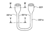
- FIG. 4 is a sectional view taken along line IV-IV in FIG. 3.
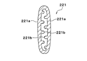
- FIG. 5 is a VV cross-sectional view of FIG. 3.
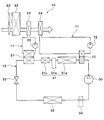
- the vehicle air conditioner 10 shown in FIG. 1 is used to adjust the interior of the vehicle interior, which is the air conditioning target space, to an appropriate temperature.
- the vehicle air conditioner 10 includes a cooling water circuit 11 and a refrigeration cycle 12. Cooling water circulates in the cooling water circuit 11.
- the refrigeration cycle 12 is a vapor compression refrigerator.
- Cooling water is a fluid as a heat medium.
- the cooling water is a liquid containing at least ethylene glycol, dimethylpolysiloxane or nanofluid, or an antifreeze liquid.
- the cooling water circuit 11 is a heat medium circuit in which the heat medium circulates. The heat transfer coefficient of cooling water is much larger than that of air.
- the cooling water circuit 11 has a pump 20, a supercooling heat exchanger 21 and an auxiliary air heater 22.
- the pump 20 is an electric pump that sucks and discharges cooling water.
- the pump 20 may be a belt-driven pump that is driven by transmitting the driving force of the engine through the belt.
- the supercooling heat exchanger 21 is a cooling water heater that absorbs heat from the refrigerant of the refrigeration cycle 12 and heats the cooling water.
- the auxiliary air heater 22 is an air heater that heats the air blown into the vehicle interior by exchanging heat between the cooling water heated by the supercooling heat exchanger 21 and the air blown by the indoor blower 23. is there.
- the pump 20, the supercooling heat exchanger 21 and the auxiliary air heater 22 are arranged in series with the cooling water circuit 11.
- the refrigeration cycle 12 includes a compressor 30, a condenser 31, a supercooling heat exchanger 21, an expansion valve 32, and an evaporator 33.
- the refrigerant of the refrigeration cycle 12 is a fluorocarbon refrigerant.
- the refrigeration cycle 12 is a subcritical refrigeration cycle in which the high-pressure side refrigerant pressure does not exceed the critical pressure of the refrigerant.
- the compressor 30 is an electric compressor that is driven by electric power supplied from a battery, and sucks, compresses, and discharges the refrigerant of the refrigeration cycle 12.
- the compressor 30 may be a belt-driven compressor that is driven by an engine belt by the driving force of the engine.
- the condenser 31 is a high-pressure side heat exchanger that condenses the high-pressure refrigerant by exchanging heat between the high-pressure refrigerant discharged from the compressor 30 and air outside the passenger compartment (hereinafter referred to as outside air).
- the condenser 31 may condense the high-pressure refrigerant by exchanging heat between the high-pressure refrigerant discharged from the compressor 30 and the cooling water.
- the condenser 31 is a subcool condenser having a condensing part 31a, a liquid storage part 31b, and a supercooling part 31c.
- the condensing unit 31a condenses the high-pressure refrigerant by exchanging heat between the high-pressure refrigerant discharged from the compressor 30 and the outside air.
- the liquid storage unit 31b separates the gas-liquid two-phase refrigerant flowing out from the condensing unit 31a into a gas-phase refrigerant and a liquid-phase refrigerant, and causes the separated liquid-phase refrigerant to flow out to the supercooling unit 31c side. It is.
- the supercooling unit 31c supercools the liquid phase refrigerant by exchanging heat between the liquid phase refrigerant flowing out of the liquid storage unit 31b and the outside air.
- the refrigeration cycle 12 constitutes a receiver cycle.
- the refrigeration cycle 12 may constitute an accumulator cycle. That is, instead of the liquid storage unit 31b and the supercooling unit 31c, a liquid storage unit 34 may be provided as shown by a two-dot chain line in FIG.
- the liquid reservoir 34 is a gas-liquid separator that separates the gas-liquid two-phase refrigerant that has flowed out of the evaporator 33 into a gas-phase refrigerant and a liquid-phase refrigerant, and causes the separated gas-phase refrigerant to flow out to the compressor 30 side. is there.
- the supercooling heat exchanger 21 is a heat exchanger that supercools the liquid refrigerant by exchanging heat between the liquid refrigerant flowing out of the condenser 31 and the cooling water of the cooling water circuit 11.
- the heat transfer coefficient of the refrigerant flowing through the supercooling heat exchanger 21 is much smaller than the heat transfer coefficient of the cooling water.
- the expansion valve 32 is a decompression unit that decompresses and expands the liquid-phase refrigerant that has flowed out of the supercooling heat exchanger 21.
- the expansion valve 32 is a temperature-type expansion valve having a temperature sensing unit that detects the degree of superheat of the evaporator 33 outlet-side refrigerant based on the temperature and pressure of the evaporator 33 outlet-side refrigerant. That is, the expansion valve 32 is a temperature-type expansion valve that adjusts the throttle passage area by a mechanical mechanism so that the degree of superheat of the refrigerant on the outlet side of the evaporator 33 falls within a predetermined range.
- the expansion valve 32 may be an electric expansion valve that adjusts the throttle passage area by an electric mechanism.
- the evaporator 33 is a low-pressure side heat exchanger that evaporates the low-pressure refrigerant by exchanging heat between the low-pressure refrigerant decompressed and expanded by the expansion valve 32 and the air blown into the vehicle interior.
- the evaporator 33 is an air cooler that cools the air blown into the vehicle interior.
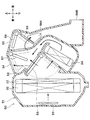
- the evaporator 33 and the auxiliary air heater 22 are accommodated in the casing 51 of the indoor air conditioning unit 50.
- An air passage through which air flows is formed inside the casing 51.
- the inside / outside air switching box is an inside / outside air switching unit that switches between air inside the vehicle interior (hereinafter referred to as inside air) and outside air.
- the indoor blower 23 sucks the air introduced by the inside / outside air switching unit and blows it to the air passage in the casing 51.
- an evaporator 33, an auxiliary air heater 22, and a heater core 24 are disposed on the downstream side of the air flow of the indoor blower 23.
- the auxiliary air heater 22 and the heater core 24 are arranged on the downstream side of the air flow from the evaporator 33.
- the heater core 24 is disposed downstream of the auxiliary air heater 22 in the air flow.
- the heater core 24 is an air heating heat exchanger that heats air by exchanging heat between engine cooling water for cooling the engine and air blown into the passenger compartment.
- a cold air bypass passage 52 is formed on the downstream side of the air flow of the evaporator 33.
- the cold air bypass passage 52 is a passage through which the cold air that has passed through the evaporator 33 flows around the auxiliary air heater 22 and the heater core 24.
- An air mix door 53 is disposed between the evaporator 33 and the auxiliary air heater 22 and the heater core 24.
- the air mix door 53 adjusts the opening degree of the cooling air bypass passage 52 and the air passage on the side of the auxiliary air heater 22 and the heater core 24, so that the cold air flowing into the auxiliary air heater 22 and the heater core 24 and the cold air bypass passage 52 It is a flow rate ratio adjusting unit that adjusts the flow rate ratio with the passing cold air.
- the air mix door 53 is a rotary door having a rotary shaft that is rotatably supported with respect to the casing 51, and a door substrate portion coupled to the rotary shaft.
- the hot air that has passed through the auxiliary air heater 22 and the heater core 24 and the cold air that has passed through the cold air bypass passage 52 are mixed, and the temperature of the conditioned air blown into the vehicle interior space is adjusted. Therefore, the temperature of the conditioned air can be adjusted to a desired temperature by adjusting the opening position of the air mix door 53.
- a defroster opening 54, a face opening 55, a foot opening 56A, and a rear foot opening 56B are formed in the most downstream portion of the casing 51 in the air flow.
- the defroster opening 54 is connected to a defroster outlet (not shown) through a defroster duct (not shown).
- the defroster outlet is disposed in the vehicle interior space. Air-conditioned air is blown out from the defroster outlet toward the inner surface of the vehicle window glass.
- the face opening 55 is connected to a face outlet (not shown) via a face duct (not shown).
- the face outlet is located in the vehicle interior space. Air-conditioned air is blown out from the face outlet toward the upper body of the passenger.
- the foot opening 56A is connected to a foot duct (not shown).
- the foot duct extends downward. Air-conditioned air is blown out from the foot outlet at the tip of the foot duct toward the feet of the front seat occupant.
- the rear foot opening 56B is connected to a rear foot duct (not shown).
- the rear foot duct extends rearward of the vehicle. Air-conditioned air is blown out from the rear foot outlet at the tip of the rear foot duct toward the feet of the rear seat occupant.
- the defroster opening 54 is opened and closed by a defroster door 57.
- the face opening 55, the foot opening 56 ⁇ / b> A, and the rear foot opening 56 ⁇ / b> B are opened and closed by a face / foot door 58.
- the face / foot door 58 opens and closes the foot opening 56A and the rear foot opening 56B by opening and closing the foot passage entrance 59.
- the foot passage inlet 59 is an air passage inlet from the vicinity of the face opening 55 to the foot opening 56A and the rear foot opening 56B.
- the defroster door 57 and the face / foot door 58 are rotary doors having a rotary shaft that is rotatably supported with respect to the casing 51, and a door substrate portion coupled to the rotary shaft.
- the auxiliary air heater 22 has a tube 221 through which cooling water flows.
- the auxiliary air heater 22 exchanges heat between the cooling water flowing inside the plurality of tubes 221 and the air flowing outside the tubes 221.
- the cross-sectional shape of both ends of the tube 221 is a perfect circle.
- part between both ends of the tube 221 is an ellipse shape.
- the part between both ends of the tube 221 has a flat flat surface 221a.
- the part between both ends of the tube 221 is bent so that the flat surfaces 221a face each other.
- the tube 221 has one bent portion, but as shown in FIG. 6, the tube 221 may have a plurality of bent portions.
- a large number of protrusions 221 b that protrude toward the inner side of the tube 221 are formed on the inner peripheral surface of the tube 221.
- a method for forming the tube 221 will be described. First, a circular pipe member 221A shown in FIG. 7 is prepared.
- the cross-sectional shape of the circular pipe member 221A is a perfect circle.
- a large number of protrusions 221b are formed in advance on the inner peripheral surface of the circular pipe member 221A so as to protrude toward the inner side of the circular pipe member 221A.
- portions other than both ends of the circular tube member 221A are crushed and flattened.
- the cross-sectional shape of a part other than both ends of the circular pipe member 221A becomes an oval shape, and a flat flat surface 221a is formed in a part other than both ends of the circular pipe member 221A.
- the tube 221 is formed by bending a portion of the circular pipe member 221A where the flat surface 221a is formed so that the flat surfaces 221a face each other.
- the control device 60 is composed of a well-known microcomputer including a CPU, a ROM, a RAM and the like and peripheral circuits thereof.
- the control device 60 performs various calculations and processes based on the control program stored in the ROM.
- Various devices to be controlled are connected to the output side of the control device 60.
- the control device 60 is a control unit that controls the operation of various devices to be controlled.
- the control target devices controlled by the control device 60 are the pump 20, the indoor blower 23, the compressor 30, the air mix door 53 of the indoor air conditioning unit 50, and the like.
- Detection signals of sensor groups such as an inside air temperature sensor 61, an outside air temperature sensor 62, a solar radiation sensor 63, an evaporator temperature sensor 64, a cooling water temperature sensor 65, and a heater core temperature sensor 66 are input to the input side of the control device 60. .
- the inside air temperature sensor 61 is an inside air temperature detection unit that detects the temperature of the inside air.
- the outside air temperature sensor 62 is an outside air temperature detector that detects the temperature of the outside air.
- the solar radiation sensor 63 is a solar radiation amount detector that detects the amount of solar radiation in the passenger compartment.
- the evaporator temperature sensor 64 is an evaporator temperature detector that detects the blown air temperature TE blown from the evaporator 33. Specifically, the evaporator temperature sensor 64 is a fin thermistor that detects the heat exchange fin temperature of the evaporator 33. The evaporator temperature sensor 64 may be a cooling water temperature sensor that detects the temperature of the refrigerant flowing through the evaporator 33.
- the cooling water temperature sensor 65 is a cooling water temperature detection unit that detects the temperature of the cooling water flowing through the cooling water circuit 11.
- the heater core temperature sensor 66 is a heat exchanger temperature detection unit that detects the temperature of the heater core 24.
- the heater core temperature sensor 66 is a cooling water temperature sensor that detects the temperature of engine cooling water flowing through the heater core 24.
- the heater core temperature sensor 66 may be a fin thermistor that detects the temperature of the heat exchange fins of the heater core 24.
- the evaporator temperature sensor 64 is an evaporator temperature detection unit that detects the blown air temperature TE (substantially the evaporator temperature) blown from the evaporator 33.
- the coolant temperature sensor 65 is a coolant temperature detector that detects the coolant temperature TW of coolant that has flowed out of the engine EG.
- the heater core temperature sensor 66 is a heater core temperature detector that detects the temperature of air blown out from the heater core 24 (substantially, the heater core temperature).
- the evaporator temperature sensor 64 specifically detects the heat exchange fin temperature of the evaporator 33.
- the evaporator temperature sensor 64 may be a temperature detector that detects the temperature of other parts of the evaporator 33.
- the evaporator temperature sensor 64 may be a temperature detector that detects the temperature of the refrigerant flowing through the evaporator 33.
- the heater core temperature sensor 66 detects the heat exchange fin temperature of the heater core 24.
- the heater core temperature sensor 66 may be a temperature detection unit that detects the temperature of other parts of the heater core 24.
- the heater core temperature sensor 66 may be a temperature detection unit that detects the temperature of the cooling water flowing through the heater core 24.
- Operation signals from various air conditioning operation switches provided on the operation panel 69 are input to the input side of the control device 60.
- the operation panel 69 is disposed near the instrument panel in the front part of the vehicle interior.
- the various air conditioning operation switches provided on the operation panel 69 are a vehicle interior temperature setting switch, an auto switch, an air conditioning switch, an air volume setting switch, an air conditioning stop switch, and the like.
- the vehicle interior temperature setting switch is a target temperature setting means for setting the vehicle interior target temperature Tset by the operation of the passenger.
- the auto switch is a switch for setting or canceling automatic control of air conditioning.
- the air conditioner switch is a switch for switching between operation and stop of cooling or dehumidification.
- the air volume setting switch is a switch for setting the air volume blown from the indoor blower.
- the air conditioning stop switch is a switch that stops air conditioning.
- Each switch may be a push switch that electrically connects electrical contacts by being mechanically pressed, or may be a touch screen that reacts by touching a predetermined area on the electrostatic panel.
- the control device 60 determines the air conditioning mode based on the outside air temperature and the target blowing temperature TAO of the vehicle cabin blowing air.
- the target blowing temperature TAO is a value determined so as to quickly bring the inside air temperature close to the desired target temperature Tset of the occupant, and is calculated by the following formula F1.
- TAO Kset ⁇ Tset ⁇ Kr ⁇ Tr ⁇ Kam ⁇ Tam ⁇ Ks ⁇ Ts + C F1
- Tset is the target temperature in the vehicle interior set by the vehicle interior temperature setting switch
- Tr is the internal air temperature detected by the internal air temperature sensor 61
- Tam is the external air temperature detected by the external air temperature sensor 62
- Ts is the amount of solar radiation detected by the solar radiation sensor 63.
- Kset, Kr, Kam, Ks are control gains
- C is a correction constant.
- the control device 60 determines the target evaporator temperature TEO based on the target blowing temperature TAO.
- the target evaporator temperature TEO is a target value of the refrigerant evaporation temperature in the evaporator 33. As the target outlet temperature TAO increases, the target evaporator temperature TEO is increased.
- the control device 60 determines the rotational speed of the compressor 30 so that the blown air temperature TE blown from the evaporator 33 approaches the target evaporator temperature TEO. Thereby, the refrigerant
- the liquid phase refrigerant radiates heat to the cooling water in the cooling water circuit 11, so that the cooling water in the cooling water circuit 11 is heated.
- the auxiliary air heater 22 exchanges heat between the cooling water heated by the supercooling heat exchanger 21 and the cold air that has passed through the evaporator 33 to heat the cold air that has passed through the evaporator 33. Thereby, the amount of heat required for reheating the cold air after passing through the evaporator 33 by the heater core 24 can be reduced.
- the control device 60 controls the number of rotations of the pump 20 to adjust the flow rate of the cooling water flowing through the supercooling heat exchanger 21 and the auxiliary air heater 22, and the supercooling heat exchanger 21 and the auxiliary air heater. The amount of heat exchange 22 is adjusted.
- the flow rate of the cooling water flowing through the supercooling heat exchanger 21 and the auxiliary air heater 22 is controlled independently of the refrigerant flow rate of the refrigeration cycle 12. Therefore, the amount of heat exchange between the supercooling heat exchanger 21 and the auxiliary air heater 22 can be adjusted appropriately, so that the air blown into the vehicle compartment in the auxiliary air heater 22 can be appropriately heated.
- the heat transfer coefficient of the cooling water in the auxiliary air heater 22 is very large compared to the heat transfer coefficient of the refrigerant in the supercooling heat exchanger 21. Therefore, in the auxiliary air heater 22, the air blown into the vehicle interior exchanges heat with cooling water having a very high heat transfer coefficient. Therefore, since the necessary heat exchange capability can be ensured even if the auxiliary air heater 22 is small in size, the size of the auxiliary air heater 22 can be reduced and the configuration of the indoor air conditioning unit 50 can be simplified.
- the supercooling heat exchanger 21 supercools the refrigerant radiated by the high pressure side heat exchanger 31 by exchanging heat between the refrigerant radiated by the high pressure side heat exchanger 31 and the cooling water.
- the auxiliary air heater 22 is disposed on the air flow downstream side of the evaporator 33 and the air flow upstream of the heater core 24 in the air passage of the air conditioning casing 51.
- the pump 20 adjusts the flow rate of the cooling water circulating between the supercooling heat exchanger 21 and the auxiliary air heater 22.
- the air blown into the vehicle compartment can be heated using the heat amount exchanged by the subcooling heat exchanger 21.
- the pump 20 adjusts the flow volume of the cooling water which circulates between the heat exchanger 21 for supercooling and the auxiliary air heater 22, in the auxiliary air heater 22, the air blown into the vehicle interior is appropriately It becomes possible to heat to.
- the necessary heat exchange amount can be obtained even if the size of the auxiliary air heater 22 is reduced. Since the heat transfer coefficient of the cooling water is larger than the heat transfer coefficient of the refrigerant in the supercooling heat exchanger 21, the air passage of the auxiliary air heater 22 is enlarged in order to reduce the ventilation resistance of the auxiliary air heater 22. However, the necessary heat exchange amount can be obtained.
- control device 60 controls the pump 20 so that the flow rate of the cooling water flowing through the auxiliary air heater 22 increases as the amount of heat necessary for heating the air cooled by the evaporator 33 increases. Control operation.
- the case where there is a large amount of heat necessary for heating the air cooled by the evaporator 33 is, for example, a case where the heating load is high.
- the case where the heating load is high is, for example, a case where the target blowing temperature TAO is high.
- the case where the target blowing temperature TAO is high is a case where the outside air temperature is low, for example.
- the control device 60 reduces the rotational speed of the compressor 30 and decreases the refrigerant flow rate of the refrigeration cycle 12. At this time, the efficiency of the refrigeration cycle 12 can be improved by increasing the amount of heat exchange in the auxiliary air heater 22.
- the controller 60 controls the pump 20 so that the flow rate of the cooling water flowing through the auxiliary air heater 22 decreases as the amount of heat necessary for heating the air cooled by the evaporator 33 decreases. Control operation.
- the case where the amount of heat necessary for heating the air cooled by the evaporator 33 is small is, for example, a case where the heating load is low.
- the case where the heating load is low is a case where the target blowing temperature TAO is low, for example.
- the case where the target blowing temperature TAO is low is a case where the outside air temperature is high, for example.
- the control device 60 increases the rotational speed of the compressor 30 and increases the refrigerant flow rate of the refrigeration cycle 12. At this time, by reducing the amount of heat exchange in the auxiliary air heater 22, it is possible to prevent the air cooled by the evaporator 33 from being excessively heated by the auxiliary air heater 22.
- control device 60 controls the operation of the pump 20 so that the flow rate of the cooling water flowing through the supercooling heat exchanger 21 decreases as the flow rate of the refrigerant increases. According to this, when there is much flow volume of a refrigerant
- control device 60 controls the operation of the pump 20 so that the flow rate of the cooling water flowing through the supercooling heat exchanger increases as the flow rate of the refrigerant decreases. According to this, when there is little flow volume of a refrigerant
- the part located between the both ends of the tube 221 has a flat shape having a flat surface 221a and is bent so that the flat surfaces face each other.
- Such a tube 221 can be formed by a very easy process. Moreover, since the cross-sectional shape of the both ends of the tube 221 is a perfect circle shape, the operation
- a protrusion 221b is formed on the inner surface of a portion of the tube 221 located between both ends. According to this, since the surface area of the inner surface of the tube 221 is expanded by the protrusion 221b, the heat transfer area of the tube 221 can be expanded. Moreover, since the projection part 221b plays the role of a support
- the auxiliary air heater 22 is disposed between the air mix door 53 and the heater core 24 in the casing 51.
- FIG. I As shown in FIG. Is disposed between the evaporator 33 and the air mix door 53 in the casing 51. Also in this embodiment, the same operational effects as those in the above embodiment can be obtained.
- a high-pressure side heat exchanger 70 is disposed on the refrigerant discharge side of the compressor 30 and on the refrigerant inlet side of the condenser 31.
- the high-pressure side heat exchanger 70 is a heat exchanger that condenses the high-pressure refrigerant by exchanging heat between the high-pressure refrigerant discharged from the compressor 30 and the cooling water of the heater core cooling water circuit 71.
- the heater core cooling water circuit 71 has a heater core pump 72.
- the heater core pump 72 is an electric pump that sucks and discharges cooling water.
- the heater core pump 72 may be a belt-driven pump that is driven by transmitting the driving force of the engine through the belt.
- the heater core 24 heats the air by exchanging heat between the cooling water heated by the high-pressure side heat exchanger 70 in the heater core cooling water circuit 71 and the air blown into the passenger compartment.
- an engine cooling circuit 74 can be connected to the cooling water circuit 11.
- the engine cooling circuit 74 includes an engine 75, an engine pump 76, a radiator 77, and a thermostat 78.
- the engine 75 is a warm-up target device that requires warm-up.
- the engine pump 76 is an electric pump that sucks and discharges cooling water.
- the engine pump 76 may be a belt-driven pump that is driven by transmitting the driving force of the engine 75 through a belt.
- the radiator 77 is a heat exchanger that exchanges heat between cooling water and outside air.
- the thermostat 78 is a cooling water temperature responsive valve.
- the cooling water temperature responsive valve is a valve provided with a mechanical mechanism that opens and closes a cooling water flow path by displacing a valve body with a thermo wax that changes in volume depending on temperature.
- the engine cooling circuit 74 is connected to the cooling water circuit 11 via the switching valve 79.
- the switching valve 79 switches between a state in which the engine cooling circuit 74 and the coolant circuit 11 are fluidly connected and a state in which the engine cooling circuit 74 is fluidly blocked.
- the operation of the switching valve 79 is controlled by the control device 60.
- the switching valve 79 is an engine flow rate adjusting unit that adjusts the flow rate of cooling water flowing through the engine 75.
- the switching valve 79 is a device flow rate adjusting unit that adjusts the flow rate of the cooling water flowing through the warm-up target device.
- the engine 75 can be warmed up using the heat radiated from the refrigerant in the supercooling heat exchanger 21.
- the EGR cooler may be arranged in the engine cooling circuit 74.
- the EGR cooler is a heat exchanger that cools the exhaust gas by exchanging heat between the exhaust gas returned to the intake side of the engine and cooling water.
- the cooling water is heated by the exhaust gas recirculation gas. Therefore, the cooling water heated by the EGR cooler can be used for heating or the like. That is, the heat of the exhaust gas recirculation gas can be used for heating or the like.
- the EGR cooler is required to have the cooling water flowing in at a predetermined temperature or higher.
- the EGR cooler is a warm-up target device that requires warm-up.
- the EGR cooler When the EGR cooler is arranged in the engine cooling circuit 74, the EGR cooler can be warmed up using the heat radiated from the refrigerant in the supercooling heat exchanger 21.
- control device 60 controls the operation of the switching valve 79 so that the flow rate of the cooling water flowing through the warm-up target device such as the engine 75 increases as the flow rate of the refrigerant in the refrigeration cycle 12 increases.
- the warming function of the warm-up target device such as the engine 75 can be increased.
- the fuel efficiency can be improved by increasing the warming function of the engine 75.
- the condenser 31 exchanges heat between the high-pressure refrigerant discharged from the compressor 30 and the cooling water in the condenser cooling water circuit 80.
- the evaporator 33 exchanges heat between the low-pressure refrigerant decompressed and expanded by the expansion valve 32 and the cooling water of the evaporator cooling water circuit 85.
- a condenser pump 81 and a second radiator 82 are arranged in the condenser cooling water circuit 80.
- the condenser pump 81 is an electric pump that sucks and discharges cooling water.
- the condenser pump 81 may be a belt-driven pump that is driven by transmitting the driving force of the engine 75 through the belt.
- the second radiator 82 is a heat exchanger that exchanges heat between the cooling water of the condenser cooling water circuit 80 and the outside air.
- the cooling water circulates between the condensing part 31a and the supercooling part 31c of the condenser 31 and the second radiator 82.
- the evaporator cooling water circuit 85 is provided with an evaporator pump 86 and a cooler core 87.
- the evaporator pump 86 is an electric pump that sucks and discharges cooling water.
- the evaporator pump 86 may be a belt-driven pump that is driven by transmitting the driving force of the engine 75 through the belt.
- the cooler core 87 is a heat exchanger that exchanges heat between the cooling water of the condenser cooling water circuit 80 and the air blown into the passenger compartment.
- a cooler core 87 is housed in the casing 51 of the indoor air conditioning unit 50 instead of the evaporator 33.
- the cooling water is used as the cooling water circulating in the cooling water circuit 11, but various media such as oil may be used as the cooling water.
- ⁇ Nanofluid may be used as the cooling water.
- a nanofluid is a fluid in which nanoparticles having a particle size of the order of nanometers are mixed.
- the effect of improving the thermal conductivity in a specific temperature range the effect of increasing the heat capacity of the cooling water, the effect of preventing the corrosion of the metal pipe and the deterioration of the rubber pipe, and the cooling water at a cryogenic temperature
- liquidity of can be acquired.
- Such an effect varies depending on the particle configuration, particle shape, blending ratio, and additional substance of the nanoparticles.
- the thermal conductivity can be improved, it is possible to obtain the same cooling efficiency even with a small amount of heat medium as compared with the cooling water using ethylene glycol.
- the amount of heat stored in the heat medium itself can be increased.
- the amount of cold storage heat of the heat medium itself is the amount of cold storage heat by sensible heat.
- the cooling and heating temperature control of the equipment using the cold storage heat can be performed for a certain amount of time. Can be realized.
- the aspect ratio of the nanoparticles is preferably 50 or more. This is because sufficient thermal conductivity can be obtained.
- the aspect ratio is a shape index that represents the ratio of the vertical and horizontal dimensions of the nanoparticles.
- Nanoparticles containing any of Au, Ag, Cu and C can be used. Specifically, Au nanoparticle, Ag nanowire, carbon nanotube (so-called CNT), graphene, graphite core-shell nanoparticle, Au nanoparticle-containing CNT, and the like can be used as the constituent atoms of the nanoparticle.
- the graphite core-shell type nanoparticle is a particle body having a structure such as a carbon nanotube surrounding the atom.
- a chlorofluorocarbon refrigerant is used as the refrigerant.
- the type of refrigerant is not limited to this, and natural refrigerants such as carbon dioxide, hydrocarbon refrigerants, and the like are used. It may be used.
- the refrigeration cycle 12 of each of the above embodiments constitutes a subcritical refrigeration cycle in which the high-pressure side refrigerant pressure does not exceed the critical pressure of the refrigerant
- the vehicle air conditioner 10 has been described.
- the present invention is not limited to this.
- the above-described embodiment can be transformed into a stationary air conditioner.
Landscapes
- Engineering & Computer Science (AREA)
- Physics & Mathematics (AREA)
- Thermal Sciences (AREA)
- Mechanical Engineering (AREA)
- General Engineering & Computer Science (AREA)
- Geometry (AREA)
- Air-Conditioning For Vehicles (AREA)
- Heat-Exchange Devices With Radiators And Conduit Assemblies (AREA)
Abstract
空調装置は、高圧側熱交換器で放熱された冷媒を熱媒体と熱交換させて過冷却する過冷却用熱交換器(21)を有する冷凍サイクル(12)と、空調ケーシング(51)の空気通路に空気を送風する送風機(23)と、空気通路に配置され、空気を冷却する空気冷却器(33、87)と、空気通路において空気冷却器の空気流れ下流側に配置され、空気冷却器で冷却された空気を加熱するヒータコア(24)と、空気通路において空気冷却器の空気流れ下流側かつ空気加熱器の空気流れ上流側に配置され、空気冷却器で冷却された空気を熱媒体と熱交換させて加熱する補助空気加熱器(22)と、過冷却用熱交換器と補助空気加熱器との間で循環する熱媒体の流量を調節する流量調節部(20)とを備える。
Description
本出願は、当該開示内容が参照によって本出願に組み込まれた、2016年3月10日に出願された日本特許出願2016-046796号を基にしている。
本開示は、空調対象空間を空調する空調装置に関する。
従来、特許文献1には、空調ダクト内に設けられた蒸発器で空気を冷却し、蒸発器の空気流れ下流側に設けたヒータコアで蒸発器から流出した空気を加熱して空調風の温度調節を行う車両用空調装置が記載されている。
この従来技術では、冷凍サイクル装置は、圧縮機、凝縮器、過冷却用熱交換器、減圧装置および蒸発器で構成されている。凝縮器は、圧縮機から吐出された冷媒を外気との熱交換により凝縮液化させる。過冷却用熱交換器は、凝縮器で凝縮された液相冷媒を更に冷却する。蒸発器は、減圧装置が減圧した冷媒を蒸発気化させる。
過冷却用熱交換器は、空調ダクト内における、蒸発器よりも空気流れ下流側、かつヒータコアよりも空気流れ上流側の部位に配置されている。ヒータコアは、エンジンを冷却する冷却水が内部を流れる。
上記従来技術では、蒸発器で冷却された空気を過冷却用熱交換器およびヒータコアで再加熱する。そのため、蒸発器で冷却された空気をヒータコアのみで再加熱する場合と比較して、ヒータコアで必要となる空気の加熱量を低減できる。
しかしながら、本開示の発明者らの検討によれば、上記従来技術では、過冷却用熱交換器を流れる冷媒の流量が圧縮機の回転数に応じて決まってしまう。一般的に、圧縮機の回転数は、蒸発器の目標温度等に応じて決定される。そのため、過冷却用熱交換器を流れる冷媒の流量が、過冷却用熱交換器で必要となる空気の加熱量とは無関係に決定されるので、過冷却用熱交換器における空気の加熱量を適切に制御することができないという問題がある。
本開示は上記点に鑑みて、過冷却用熱交換器で熱交換された熱量を利用して、車室内へ送風される空気を適切に加熱可能な空調装置を提供することを目的とする。
本開示の一つの特徴例による空調装置は、
冷媒を吸入して吐出する圧縮機と、圧縮機から吐出された冷媒を放熱させる高圧側熱交換器と、高圧側熱交換器で放熱された冷媒と熱媒体とを熱交換させることによって、高圧側熱交換器で放熱された冷媒を過冷却する過冷却用熱交換器とを有する冷凍サイクルと、
空調対象空間へ吹き出される空気が流れる空気通路を形成する空調ケーシングと、
空気通路に空気を送風する送風機と、
空気通路に配置され、空気を冷却する空気冷却器と、
空気通路において空気冷却器の空気流れ下流側に配置され、空気冷却器で冷却された空気を加熱する空気加熱器と、
空気通路において空気冷却器の空気流れ下流側かつ空気加熱器の空気流れ上流側に配置され、空気冷却器で冷却された空気を熱媒体と熱交換させて加熱する補助空気加熱器と、
過冷却用熱交換器と補助空気加熱器との間で循環する熱媒体の流量を調節する流量調節部とを備える。
冷媒を吸入して吐出する圧縮機と、圧縮機から吐出された冷媒を放熱させる高圧側熱交換器と、高圧側熱交換器で放熱された冷媒と熱媒体とを熱交換させることによって、高圧側熱交換器で放熱された冷媒を過冷却する過冷却用熱交換器とを有する冷凍サイクルと、
空調対象空間へ吹き出される空気が流れる空気通路を形成する空調ケーシングと、
空気通路に空気を送風する送風機と、
空気通路に配置され、空気を冷却する空気冷却器と、
空気通路において空気冷却器の空気流れ下流側に配置され、空気冷却器で冷却された空気を加熱する空気加熱器と、
空気通路において空気冷却器の空気流れ下流側かつ空気加熱器の空気流れ上流側に配置され、空気冷却器で冷却された空気を熱媒体と熱交換させて加熱する補助空気加熱器と、
過冷却用熱交換器と補助空気加熱器との間で循環する熱媒体の流量を調節する流量調節部とを備える。
これによると、補助空気加熱器において、過冷却用熱交換器で熱交換された熱量を利用して、車室内へ送風される空気を加熱できる。そして、流量調節部が、過冷却用熱交換器と補助空気加熱器との間で循環する熱媒体の流量を調節するので、補助空気加熱器において、車室内へ送風される空気を適切に加熱することが可能になる。
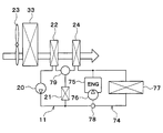
以下、実施形態について図に基づいて説明する。以下の各実施形態相互において、互いに同一もしくは均等である部分には、図中、同一符号を付してある。
(第1実施形態)
図1に示す車両用空調装置10は、空調対象空間である車室内を適切な温度に調整するために用いられる。車両用空調装置10は、冷却水回路11および冷凍サイクル12を備えている。冷却水回路11には冷却水が循環する。冷凍サイクル12は蒸気圧縮式冷凍機である。
図1に示す車両用空調装置10は、空調対象空間である車室内を適切な温度に調整するために用いられる。車両用空調装置10は、冷却水回路11および冷凍サイクル12を備えている。冷却水回路11には冷却水が循環する。冷凍サイクル12は蒸気圧縮式冷凍機である。
冷却水は、熱媒体としての流体である。例えば、冷却水は、少なくともエチレングリコール、ジメチルポリシロキサンもしくはナノ流体を含む液体、または不凍液体である。冷却水回路11は、熱媒体が循環する熱媒体回路である。冷却水の熱伝達率は、空気の熱伝達率よりも非常に大きい。
冷却水回路11は、ポンプ20、過冷却用熱交換器21および補助空気加熱器22を有している。ポンプ20は、冷却水を吸入して吐出する電動ポンプである。ポンプ20は、エンジンの駆動力をベルトを介して動力伝達することによって駆動されるベルト駆動式ポンプであってもよい。
過冷却用熱交換器21は、冷凍サイクル12の冷媒から吸熱して冷却水を加熱する冷却水加熱器である。補助空気加熱器22は、過冷却用熱交換器21で加熱された冷却水と室内送風機23によって送風される空気とを熱交換させて、車室内へ送風される空気を加熱する空気加熱器である。
ポンプ20、過冷却用熱交換器21および補助空気加熱器22は、冷却水回路11に直列に配置されている。
冷凍サイクル12は、圧縮機30、凝縮器31、過冷却用熱交換器21、膨張弁32、および蒸発器33を有している。冷凍サイクル12の冷媒はフロン系冷媒である。冷凍サイクル12は、高圧側冷媒圧力が冷媒の臨界圧力を超えない亜臨界冷凍サイクルである。
圧縮機30は、電池から供給される電力によって駆動される電動圧縮機であり、冷凍サイクル12の冷媒を吸入して圧縮して吐出する。圧縮機30は、エンジンの駆動力によってエンジンベルトで駆動されるベルト駆動式圧縮機であってもよい。
凝縮器31は、圧縮機30から吐出された高圧冷媒と車室外の空気(以下、外気と言う。)とを熱交換させることによって高圧冷媒を凝縮させる高圧側熱交換器である。凝縮器31は、圧縮機30から吐出された高圧冷媒と冷却水とを熱交換させることによって高圧冷媒を凝縮させてもよい。
凝縮器31は、凝縮部31a、貯液部31bおよび過冷却部31cを有するサブクールコンデンサである。凝縮部31aは、圧縮機30から吐出された高圧冷媒と外気とを熱交換させることによって高圧冷媒を凝縮させる。貯液部31bは、凝縮部31aから流出した気液二相冷媒を気相冷媒と液相冷媒とに分離して、分離された液相冷媒を過冷却部31c側に流出させる気液分離部である。過冷却部31cは、貯液部31bから流出した液相冷媒と外気とを熱交換させることによって液相冷媒を過冷却する。
これにより、冷凍サイクル12は、レシーバーサイクルを構成している。冷凍サイクル12は、アキュムレータサイクルを構成していてもよい。すなわち、貯液部31bおよび過冷却部31cの代わりに、図1中に二点鎖線で示すように貯液器34が設けられていてもよい。貯液器34は、蒸発器33から流出した気液二相冷媒を気相冷媒と液相冷媒とに分離して、分離された気相冷媒を圧縮機30側に流出させる気液分離器である。
過冷却用熱交換器21は、凝縮器31から流出した液相冷媒と冷却水回路11の冷却水とを熱交換させることによって液相冷媒を過冷却する熱交換器である。過冷却用熱交換器21を流れる冷媒の熱伝達率は、冷却水の熱伝達率よりも非常に小さい。
膨張弁32は、過冷却用熱交換器21から流出した液相冷媒を減圧膨張させる減圧部である。膨張弁32は、蒸発器33出口側冷媒の温度および圧力に基づいて蒸発器33出口側冷媒の過熱度を検出する感温部を有する温度式膨張弁である。すなわち、膨張弁32は、蒸発器33出口側冷媒の過熱度が予め定めた所定範囲となるように機械的機構によって絞り通路面積を調節する温度式膨張弁である。膨張弁32は、電気的機構によって絞り通路面積を調節する電気式膨張弁であってもよい。
蒸発器33は、膨張弁32で減圧膨張された低圧冷媒と車室内へ送風される空気とを熱交換させることによって低圧冷媒を蒸発させる低圧側熱交換器である。蒸発器33は、車室内へ送風される空気を冷却する空気冷却器である。
図2に示すように、蒸発器33および補助空気加熱器22は、室内空調ユニット50のケーシング51に収容されている。ケーシング51の内部には、空気が流れる空気通路が形成されている。
ケーシング51内において空気流れ最上流部には、図示しない内外気切替箱および室内送風機23が配置されている。図2では、室内送風機23を模式的に図示している。内外気切替箱は、車室内の空気(以下、内気と言う。)と外気とを切替導入する内外気切替部である。
室内送風機23は、内外気切替部によって導入された空気を吸入してケーシング51内の空気通路に送風する。ケーシング51内において室内送風機23の空気流れ下流側には、蒸発器33、補助空気加熱器22およびヒータコア24が配置されている。補助空気加熱器22およびヒータコア24は、蒸発器33よりも空気流れ下流側に配置されている。ヒータコア24は、補助空気加熱器22よりも空気流れ下流側に配置されている。
ヒータコア24は、エンジンを冷却するエンジン冷却水と車室内へ送風される空気とを熱交換させて空気を加熱する空気加熱用熱交換器である。
ケーシング51内において蒸発器33の空気流れ下流側には、冷風バイパス通路52が形成されている。冷風バイパス通路52は、蒸発器33通過後の冷風が補助空気加熱器22およびヒータコア24を迂回して流れる通路である。
蒸発器33と補助空気加熱器22およびヒータコア24との間には、エアミックスドア53が配置されている。エアミックスドア53は、冷風バイパス通路52と補助空気加熱器22およびヒータコア24側の通風路の開度を調整することにより、補助空気加熱器22およびヒータコア24に流入する冷風と冷風バイパス通路52を通過する冷風との流量割合を調整する流量割合調整部である。
エアミックスドア53は、ケーシング51に対して回転可能に支持された回転軸と、回転軸に結合されたドア基板部とを有する回転式ドアである。
ケーシング51内において、補助空気加熱器22およびヒータコア24を通過した温風と冷風バイパス通路52を通過した冷風とが混合されて、車室内空間に吹き出される空調風の温度調整がなされる。したがって、エアミックスドア53の開度位置を調整することによって、空調風の温度を所望温度に調整できる。
ケーシング51の空気流れ最下流部には、デフロスタ開口部54、フェイス開口部55、フット開口部56Aおよびリヤフット開口部56Bが形成されている。
デフロスタ開口部54は、図示しないデフロスタダクトを介して、図示しないデフロスタ吹出口に接続されている。デフロスタ吹出口は車室内空間に配置されている。デフロスタ吹出口から車両窓ガラスの内面に向けて空調風が吹き出される。
フェイス開口部55は、図示しないフェイスダクトを介して、図示しないフェイス吹出口に接続されている。フェイス吹出口は車室内空間に配置されている。フェイス吹出口から乗員の上半身側に向けて空調風が吹き出される。
フット開口部56Aは、図示しないフットダクトに接続されている。フットダクトは下方に向かって延びている。フットダクトの先端部のフット吹出口から前席乗員の足元部に向けて空調風が吹き出される。
リヤフット開口部56Bは、図示しないリヤフットダクトに接続されている。リヤフットダクトは車両後方へ延びている。リヤフットダクトの先端部のリヤフット吹出口から後席乗員の足元部に向けて空調風が吹き出される。
デフロスタ開口部54は、デフロスタドア57によって開閉される。フェイス開口部55、フット開口部56Aおよびリヤフット開口部56Bは、フェイス・フットドア58によって開閉される。
フェイス・フットドア58は、フット通路入口部59を開閉することによって、フット開口部56Aおよびリヤフット開口部56Bを開閉する。フット通路入口部59は、フェイス開口部55近傍からフット開口部56Aおよびリヤフット開口部56Bに至る空気通路の入口部である。
デフロスタドア57およびフェイス・フットドア58は、ケーシング51に対して回転可能に支持された回転軸と、回転軸に結合されたドア基板部とを有する回転式ドアである。
図3に示すように、補助空気加熱器22は、冷却水が流れるチューブ221を有している。補助空気加熱器22は、複数本のチューブ221の内部を流れる冷却水と、チューブ221の外部を流れる空気とを熱交換させる。
図4に示すように、チューブ221の両端部の断面形状は正円形状になっている。図5に示すように、チューブ221のうち両端部同士の間の部位の断面形状は長円形状になっている。チューブ221のうち両端部同士の間の部位は、平坦な扁平面221aを有している。
図3に示すように、チューブ221のうち両端部同士の間の部位は、扁平面221a同士が向かい合うように屈曲している。図3の例では、チューブ221の屈曲部は1箇所であるが、図6に示すように、チューブ221の屈曲部は複数箇所あってもよい。
図4、図5に示すように、チューブ221の内周面には、チューブ221の内方側に向かって突出する多数の突起部221bが形成されている。
チューブ221の成形方法を説明する。まず、図7に示す円管部材221Aを用意する。円管部材221Aの断面形状は正円形状になっている。円管部材221Aの内周面には、円管部材221Aの内方側に向かって突出する多数の突起部221bが予め形成されている。
次に、図8に示すように円管部材221Aのうち両端部以外の部位を潰して扁平化する。これにより、円管部材221Aのうち両端部以外の部位の断面形状が長円形状になり、円管部材221Aのうち両端部以外の部位に平坦な扁平面221aが形成される。
このとき、円管部材221Aの内周面において多数の突起部221bが支柱の役割を果たすことによって、円管部材221Aのうち両端部以外の部位が潰れすぎることを防止できる。
そして、円管部材221Aのうち扁平面221aが形成された部位を、扁平面221a同士が向かい合うように曲げ加工することによって、チューブ221が成形される。
次に、車両用空調装置10の電気制御部を図9に基づいて説明する。制御装置60は、CPU、ROMおよびRAM等を含む周知のマイクロコンピュータとその周辺回路から構成されている。制御装置60は、ROM内に記憶された制御プログラムに基づいて各種演算、処理を行う。制御装置60の出力側には各種制御対象機器が接続されている。制御装置60は、各種制御対象機器の作動を制御する制御部である。
制御装置60によって制御される制御対象機器は、ポンプ20、室内送風機23、圧縮機30、室内空調ユニット50のエアミックスドア53等である。
制御装置60の入力側には、内気温度センサ61、外気温度センサ62、日射センサ63、蒸発器温度センサ64、冷却水温度センサ65、ヒータコア温度センサ66等のセンサ群の検出信号が入力される。
内気温度センサ61は、内気の温度を検出する内気温度検出部である。外気温度センサ62は、外気の温度を検出する外気温度検出部である。日射センサ63は、車室内の日射量を検出する日射量検出部である。
蒸発器温度センサ64は、蒸発器33から吹き出される吹出空気温度TEを検出する蒸発器温度検出部である。具体的には、蒸発器温度センサ64は、蒸発器33の熱交換フィン温度を検出するフィンサーミスタである。蒸発器温度センサ64は、蒸発器33を流通する冷媒の温度を検出する冷却水温度センサであってもよい。
冷却水温度センサ65は、冷却水回路11を流れる冷却水の温度を検出する冷却水温度検出部である。
ヒータコア温度センサ66は、ヒータコア24の温度を検出する熱交換器温度検出部である。例えば、ヒータコア温度センサ66は、ヒータコア24を流れるエンジン冷却水の温度を検出する冷却水温度センサである。ヒータコア温度センサ66は、ヒータコア24の熱交換フィンの温度を検出するフィンサーミスタであってもよい。
蒸発器温度センサ64は、蒸発器33から吹き出される吹出空気温度TE(実質的には、蒸発器温度)を検出する蒸発器温度検出部である。冷却水温度センサ65は、エンジンEGから流出した冷却水の冷却水温度TWを検出する冷却水温度検出部である。ヒータコア温度センサ66は、ヒータコア24から吹き出される吹出空気温度TH(実質的には、ヒータコア温度)を検出するヒータコア温度検出部である。
蒸発器温度センサ64は、具体的には、蒸発器33の熱交換フィン温度を検出している。蒸発器温度センサ64は、蒸発器33のその他の部位の温度を検出する温度検出部であってもよい。蒸発器温度センサ64は、蒸発器33を流通する冷媒の温度を検出する温度検出部であってもよい。
ヒータコア温度センサ66は、具体的には、ヒータコア24の熱交換フィン温度を検出している。ヒータコア温度センサ66は、ヒータコア24のその他の部位の温度を検出する温度検出部であってもよい。ヒータコア温度センサ66は、ヒータコア24を流通する冷却水の温度を検出する温度検出部であってもよい。
制御装置60の入力側には、操作パネル69に設けられた各種空調操作スイッチからの操作信号が入力される。例えば、操作パネル69は、車室内前部の計器盤付近に配置されている。
操作パネル69に設けられた各種空調操作スイッチは、車室内温度設定スイッチ、オートスイッチ、エアコンスイッチ、風量設定スイッチおよび空調停止スイッチ等である。
車室内温度設定スイッチは、乗員の操作によって車室内目標温度Tsetを設定する目標温度設定手段である。オートスイッチは、空調の自動制御を設定または解除するスイッチである。エアコンスイッチは、冷房または除湿の作動・停止を切り替えるスイッチである。風量設定スイッチは、室内送風機から送風される風量を設定するスイッチである。空調停止スイッチは、空調を停止させるスイッチである。
各スイッチは、機械的に押し込まれることによって電気接点を導通させる方式のプッシュスイッチでもよいし、静電パネル上の所定の領域に触れられることによって反応するタッチスクリーン方式でもよい。
制御装置60は、外気温度と車室内吹出空気の目標吹出温度TAOとに基づいて空調モードを決定する。目標吹出温度TAOは、内気の温度を速やかに乗員の所望の目標温度Tsetに近づけるために決定される値であって、下記数式F1により算出される。
TAO=Kset×Tset-Kr×Tr-Kam×Tam-Ks×Ts+C …F1
この数式において、Tsetは車室内温度設定スイッチによって設定された車室内の目標温度であり、Trは内気温度センサ61によって検出された内気温度であり、Tamは外気温度センサ62によって検出された外気温度であり、Tsは日射センサ63によって検出された日射量である。Kset、Kr、Kam、Ksは制御ゲインであり、Cは補正用の定数である。
この数式において、Tsetは車室内温度設定スイッチによって設定された車室内の目標温度であり、Trは内気温度センサ61によって検出された内気温度であり、Tamは外気温度センサ62によって検出された外気温度であり、Tsは日射センサ63によって検出された日射量である。Kset、Kr、Kam、Ksは制御ゲインであり、Cは補正用の定数である。
制御装置60は、目標吹出温度TAOに基づいて目標蒸発器温度TEOを決定する。目標蒸発器温度TEOは、蒸発器33における冷媒蒸発温度の目標値である。目標吹出温度TAOが上昇するに伴って、目標蒸発器温度TEOを上昇させる。
制御装置60は、蒸発器33から吹き出される吹出空気温度TEが目標蒸発器温度TEOに近づくように圧縮機30の回転数を決定する。これにより、冷凍サイクル12の冷媒流量が制御される。
次に、上記構成における作動を説明する。エンジンが作動している状態において制御装置60がポンプ20および圧縮機30を作動させると、過冷却用熱交換器21が凝縮器31から流出した液相冷媒を過冷却するので、冷凍サイクル12のサイクル効率を向上できる。
過冷却用熱交換器21では、液相冷媒が冷却水回路11の冷却水に放熱するので、冷却水回路11の冷却水が加熱される。補助空気加熱器22は、過冷却用熱交換器21で加熱された冷却水と蒸発器33通過後の冷風とを熱交換させて蒸発器33通過後の冷風を加熱する。これにより、ヒータコア24で蒸発器33通過後の冷風を再加熱するために必要となる熱量を低減できる。
制御装置60がポンプ20の回転数を制御することによって、過冷却用熱交換器21および補助空気加熱器22を流れる冷却水の流量が調節され、過冷却用熱交換器21および補助空気加熱器22の熱交換量が調節される。
過冷却用熱交換器21および補助空気加熱器22を流れる冷却水の流量は、冷凍サイクル12の冷媒流量に対して独立に制御される。そのため、過冷却用熱交換器21および補助空気加熱器22の熱交換量を適切に調節できるので、補助空気加熱器22において車室内へ送風される空気を適切に加熱できる。
補助空気加熱器22における冷却水の熱伝達率は、過冷却用熱交換器21における冷媒の熱伝達率と比較して非常に大きい。そのため、補助空気加熱器22では、車室内へ送風される空気が、熱伝達率が非常に大きい冷却水と熱交換することとなる。したがって、補助空気加熱器22の体格が小さくても必要な熱交換能力を確保できるので、補助空気加熱器22の体格を小型化して室内空調ユニット50の構成を簡素化できる。
本実施形態では、過冷却用熱交換器21は、高圧側熱交換器31で放熱された冷媒と冷却水とを熱交換させることによって、高圧側熱交換器31で放熱された冷媒を過冷却する。補助空気加熱器22は、空調ケーシング51の空気通路において蒸発器33の空気流れ下流側かつヒータコア24の空気流れ上流側に配置されている。ポンプ20は、過冷却用熱交換器21と補助空気加熱器22との間で循環する冷却水の流量を調節する。
これによると、補助空気加熱器22において、過冷却用熱交換器21で熱交換された熱量を利用して、車室内へ送風される空気を加熱できる。そして、ポンプ20が、過冷却用熱交換器21と補助空気加熱器22との間で循環する冷却水の流量を調節するので、補助空気加熱器22において、車室内へ送風される空気を適切に加熱することが可能になる。
冷却水の熱伝達率は、過冷却用熱交換器21における冷媒の熱伝達率よりも大きいので、補助空気加熱器22の体格を小型化しても必要な熱交換量を得ることができる。冷却水の熱伝達率は、過冷却用熱交換器21における冷媒の熱伝達率よりも大きいので、補助空気加熱器22の通風抵抗を小さくするために補助空気加熱器22の空気通路を拡大しても必要な熱交換量を得ることができる。
本実施形態では、制御装置60は、蒸発器33で冷却された空気を加熱するために必要な熱量が多くなるにつれて、補助空気加熱器22を流れる冷却水の流量が増加するようにポンプ20の作動を制御する。
これによると、蒸発器33で冷却された空気を加熱するために必要な熱量が多い場合、補助空気加熱器22における熱交換量が増加するので、ヒータコア24における空気の加熱量が増加することを抑制できる。
蒸発器33で冷却された空気を加熱するために必要な熱量が多い場合とは、例えば暖房負荷が高い場合である。暖房負荷が高い場合とは、例えば目標吹出温度TAOが高い場合である。目標吹出温度TAOが高い場合とは、例えば外気温度が低い場合である。
外気温度が低い場合、蒸発器33に要求される除湿能力が低くなるため、制御装置60は圧縮機30の回転数を低くして冷凍サイクル12の冷媒流量を少なくする。このとき、補助空気加熱器22における熱交換量を増加させることによって、冷凍サイクル12の効率を向上できる。
本実施形態では、制御装置60は、蒸発器33で冷却された空気を加熱するために必要な熱量が少なくなるにつれて、補助空気加熱器22を流れる冷却水の流量が減少するようにポンプ20の作動を制御する。
これによると、蒸発器33で冷却された空気を加熱するために必要な熱量が少ない場合、補助空気加熱器22における熱交換量が減少するので、蒸発器33で冷却された空気を補助空気加熱器22で過剰に加熱してしまうことを抑制できる。
蒸発器33で冷却された空気を加熱するために必要な熱量が少ない場合とは、例えば暖房負荷が低い場合である。暖房負荷が低い場合とは、例えば目標吹出温度TAOが低い場合である。目標吹出温度TAOが低い場合とは、例えば外気温度が高い場合である。
外気温度が高い場合、蒸発器33に要求される除湿能力が高くなるため、制御装置60は圧縮機30の回転数を高くして冷凍サイクル12の冷媒流量を多くする。このとき、補助空気加熱器22における熱交換量を減少させることによって、蒸発器33で冷却された空気を補助空気加熱器22で過剰に加熱してしまうことを抑制できる。
例えば、最大冷房時に、蒸発器33で冷却された空気が補助空気加熱器22で過剰に再加熱されて目標吹出温度TAOよりも高温になってしまうことを抑制できる。
本実施形態では、制御装置60は、冷媒の流量が多くなるにつれて、過冷却用熱交換器21を流れる冷却水の流量が減少するようにポンプ20の作動を制御する。これによると、冷媒の流量が多い場合、過冷却用熱交換器21における熱交換量が過剰になることを抑制できる。
本実施形態では、制御装置60は、冷媒の流量が少なくなるにつれて、過冷却用熱交換器を流れる冷却水の流量が増加するようにポンプ20の作動を制御する。これによると、冷媒の流量が少ない場合、過冷却用熱交換器における熱交換量が不足することを抑制できる。
本実施形態では、チューブ221のうち、その両端部間に位置する部位は、扁平面221aを有する扁平形状になっており、且つ扁平面同士が向かい合いように屈曲した形状になっている。
このようなチューブ221は、非常に容易な加工によって成形可能である。また、チューブ221の両端部の断面形状は正円形状になっているので、冷却水回路11の冷却水ホースをチューブ221に接続する作業が非常に簡単である。
本実施形態では、チューブ221のうち、その両端部間に位置する部位の内面には突起部221bが形成されている。これによると、突起部221bによってチューブ221内面の表面積が拡大されるので、チューブ221の伝熱面積を拡大できる。また、チューブ221を扁平形状に加工するときに突起部221bが支柱の役割を果たすので、チューブ221が潰れすぎて不良成形品となることを抑制できる。
(第2実施形態)
上記実施形態では、補助空気加熱器22は、ケーシング51内においてエアミックスドア53とヒータコア24との間に配置されているが、本実施形態では、図10に示すように、補助空気加熱器22は、ケーシング51内において蒸発器33とエアミックスドア53との間に配置されている。本実施形態においても、上記実施形態と同様の作用効果を奏することができる。
上記実施形態では、補助空気加熱器22は、ケーシング51内においてエアミックスドア53とヒータコア24との間に配置されているが、本実施形態では、図10に示すように、補助空気加熱器22は、ケーシング51内において蒸発器33とエアミックスドア53との間に配置されている。本実施形態においても、上記実施形態と同様の作用効果を奏することができる。
(第3実施形態)
本実施形態では、図11に示すように、冷凍サイクル12において、圧縮機30の冷媒吐出側かつ凝縮器31の冷媒入口側に高圧側熱交換器70が配置されている。
本実施形態では、図11に示すように、冷凍サイクル12において、圧縮機30の冷媒吐出側かつ凝縮器31の冷媒入口側に高圧側熱交換器70が配置されている。
高圧側熱交換器70は、圧縮機30から吐出された高圧冷媒とヒータコア冷却水回路71の冷却水とを熱交換させることによって高圧冷媒を凝縮させる熱交換器である。
ヒータコア冷却水回路71は、ヒータコアポンプ72を有している。ヒータコアポンプ72は、冷却水を吸入して吐出する電動ポンプである。ヒータコアポンプ72は、エンジンの駆動力をベルトを介して動力伝達することによって駆動されるベルト駆動式ポンプであってもよい。
本実施形態では、ヒータコア24は、ヒータコア冷却水回路71において高圧側熱交換器70で加熱された冷却水と車室内へ送風される空気とを熱交換させて空気を加熱する。
本実施形態においても、上記実施形態と同様の作用効果を奏することができる。
(第4実施形態)
本実施形態では、図12に示すように、冷却水回路11にエンジン冷却回路74を接続可能になっている。
本実施形態では、図12に示すように、冷却水回路11にエンジン冷却回路74を接続可能になっている。
エンジン冷却回路74は、エンジン75、エンジンポンプ76、ラジエータ77、サーモスタット78を有している。エンジン75は、暖機を必要とする暖機対象機器である。エンジンポンプ76は、冷却水を吸入して吐出する電動ポンプである。エンジンポンプ76は、エンジン75の駆動力をベルトを介して動力伝達することによって駆動されるベルト駆動式ポンプであってもよい。
ラジエータ77は、冷却水と外気とを熱交換させる熱交換器である。サーモスタット78は冷却水温度応動弁である。冷却水温度応動弁は、温度によって体積変化するサーモワックスによって弁体を変位させて冷却水流路を開閉する機械的機構を備える弁である。
エンジン冷却回路74は、切替弁79を介して冷却水回路11に接続されている。切替弁79は、エンジン冷却回路74と冷却水回路11とを流体的に接続する状態と、流体的に遮断する状態とを切り替える。切替弁79の作動は、制御装置60によって制御される。切替弁79は、エンジン75を流れる冷却水の流量を調節するエンジン流量調節部である。切替弁79は、暖機対象機器を流れる冷却水の流量を調節する機器流量調節部である。
本実施形態では、過冷却用熱交換器21で冷媒から放熱された熱を利用してエンジン75を暖機できる。
エンジン冷却回路74にEGRクーラが配置されていてもよい。EGRクーラは、エンジンの吸気側に戻される排気ガスと冷却水とを熱交換して排気ガスを冷却する熱交換器である。
EGRクーラでは、排気再循環ガスによって冷却水が加熱される。そのため、EGRクーラで加熱された冷却水を暖房等に利用することが可能である。すなわち、排気再循環ガスの熱を暖房等に利用することが可能である。
しかしながら、EGRクーラに流入する冷却水の温度が低すぎると、EGRクーラで排気再循環ガスが冷却される際に凝縮水が発生するので腐食が発生しやすくなる。そのため、冷却水の温度がある程度上昇するまでは、EGRクーラに冷却水を流入させることができないので排気再循環ガスの熱を暖房等に利用できないのみならず、冷却水による排気ガスの冷却ができないため、排気ガスをエンジンに再循環させることができずに燃費向上効果を得ることもできない。
すなわち、EGRクーラは、流入する冷却水が所定温度以上であることが要求される。このような機器に対しては、所定温度以上の冷却水を早期に流入させることが望ましい。したがって、EGRクーラは、暖機を必要とする暖機対象機器である。
エンジン冷却回路74にEGRクーラが配置されている場合、過冷却用熱交換器21で冷媒から放熱された熱を利用してEGRクーラを暖機できる。
本実施形態では、制御装置60は、冷凍サイクル12の冷媒の流量が多くなるにつれて、エンジン75等の暖機対象機器を流れる冷却水の流量が増加するように切替弁79の作動を制御する。
これによると、冷凍サイクル12の冷媒の流量が多くて過冷却用熱交換器21における熱交換量を多く確保できる場合、エンジン75等の暖機対象機器の暖機能力を高くできる。エンジン75の暖機能力を高くすることによって燃費を向上させることができる。
(第5実施形態)
本実施形態では、図13に示すように、凝縮器31は、圧縮機30から吐出された高圧冷媒と、凝縮器冷却水回路80の冷却水とを熱交換させる。蒸発器33は、膨張弁32で減圧膨張された低圧冷媒と蒸発器冷却水回路85の冷却水とを熱交換させる。
本実施形態では、図13に示すように、凝縮器31は、圧縮機30から吐出された高圧冷媒と、凝縮器冷却水回路80の冷却水とを熱交換させる。蒸発器33は、膨張弁32で減圧膨張された低圧冷媒と蒸発器冷却水回路85の冷却水とを熱交換させる。
凝縮器冷却水回路80には、凝縮器ポンプ81および第2ラジエータ82が配置されている。凝縮器ポンプ81は、冷却水を吸入して吐出する電動ポンプである。凝縮器ポンプ81は、エンジン75の駆動力をベルトを介して動力伝達することによって駆動されるベルト駆動式ポンプであってもよい。第2ラジエータ82は、凝縮器冷却水回路80の冷却水と外気とを熱交換させる熱交換器である。
これにより、凝縮器31の凝縮部31aおよび過冷却部31cと第2ラジエータ82との間で冷却水が循環する。
蒸発器冷却水回路85には、蒸発器ポンプ86およびクーラコア87が配置されている。蒸発器ポンプ86は、冷却水を吸入して吐出する電動ポンプである。蒸発器ポンプ86は、エンジン75の駆動力をベルトを介して動力伝達することによって駆動されるベルト駆動式ポンプであってもよい。
クーラコア87は、凝縮器冷却水回路80の冷却水と車室内へ送風される空気とを熱交換させる熱交換器である。本実施形態では、蒸発器33の代わりにクーラコア87が室内空調ユニット50のケーシング51に収容されている。
本実施形態においても、上記実施形態と同様の作用効果を奏することができる。
(他の実施形態)
上記実施形態を適宜組み合わせ可能である。上記実施形態を例えば以下のように種々変形可能である。
上記実施形態を適宜組み合わせ可能である。上記実施形態を例えば以下のように種々変形可能である。
(1)上記各実施形態では、冷却水回路11を循環する冷却水として冷却水を用いているが、油などの各種媒体を冷却水として用いてもよい。
冷却水として、ナノ流体を用いてもよい。ナノ流体とは、粒子径がナノメートルオーダーのナノ粒子が混入された流体のことである。ナノ粒子を冷却水に混入させることで、エチレングリコールを用いた冷却水(いわゆる不凍液のように凝固点を低下させる作用効果に加えて、次のような作用効果を得ることができる。
すなわち、特定の温度帯での熱伝導率を向上させる作用効果、冷却水の熱容量を増加させる作用効果、金属配管の防食効果やゴム配管の劣化を防止する作用効果、および極低温での冷却水の流動性を高める作用効果を得ることができる。
このような作用効果は、ナノ粒子の粒子構成、粒子形状、配合比率、付加物質によって様々に変化する。
これによると、熱伝導率を向上させることができるので、エチレングリコールを用いた冷却水と比較して少ない量の熱媒体であっても同等の冷却効率を得ることが可能になる。
また、熱媒体の熱容量を増加させることができるので、熱媒体自体の蓄冷熱量を増加させることができる。熱媒体自体の蓄冷熱量は、顕熱による蓄冷熱量である。
蓄冷熱量を増加させることにより、圧縮機30を作動させない状態であっても、ある程度の時間は蓄冷熱を利用した機器の冷却、加熱の温調が実施できるため、車両用空調装置10の省動力化が可能になる。
ナノ粒子のアスペクト比は50以上であるのが好ましい。十分な熱伝導率を得ることができるからである。なお、アスペクト比は、ナノ粒子の縦×横の比率を表す形状指標である。
ナノ粒子としては、Au、Ag、CuおよびCのいずれかを含むものを用いることができる。具体的には、ナノ粒子の構成原子として、Auナノ粒子、Agナノワイヤー、カーボンナノチューブ(いわゆるCNT)、グラフェン、グラファイトコアシェル型ナノ粒子、およびAuナノ粒子含有CNTなどを用いることができる。グラファイトコアシェル型ナノ粒子とは、上記原子を囲むようにカーボンナノチューブ等の構造体があるような粒子体のことである。
(2)上記各実施形態の冷凍サイクル12では、冷媒としてフロン系冷媒を用いているが、冷媒の種類はこれに限定されるものではなく、二酸化炭素等の自然冷媒や炭化水素系冷媒等を用いてもよい。
(3)上記各実施形態の冷凍サイクル12は、高圧側冷媒圧力が冷媒の臨界圧力を超えない亜臨界冷凍サイクルを構成しているが、高圧側冷媒圧力が冷媒の臨界圧力を超える超臨界冷凍サイクルを構成していてもよい。
(4)上述の各実施形態では、車両用空調装置10について説明したが、これに限定されず、例えば、上記実施形態を据置型の空調装置に変形可能である。
Claims (9)
- 冷媒を吸入して吐出する圧縮機(30)と、前記圧縮機から吐出された前記冷媒を放熱させる高圧側熱交換器(31)と、前記高圧側熱交換器で放熱された前記冷媒と熱媒体とを熱交換させることによって、前記高圧側熱交換器で放熱された前記冷媒を過冷却する過冷却用熱交換器(21)とを有する冷凍サイクル(12)と、
空調対象空間へ吹き出される空気が流れる空気通路を形成する空調ケーシング(51)と、
前記空気通路に空気を送風する送風機(23)と、
前記空気通路に配置され、前記空気を冷却する空気冷却器(33、87)と、
前記空気通路において前記空気冷却器の空気流れ下流側に配置され、前記空気冷却器で冷却された前記空気を加熱する空気加熱器(24)と、
前記空気通路において前記空気冷却器の空気流れ下流側かつ前記空気加熱器の空気流れ上流側に配置され、前記空気冷却器で冷却された前記空気を前記熱媒体と熱交換させて加熱する補助空気加熱器(22)と、
前記過冷却用熱交換器と前記補助空気加熱器との間で循環する前記熱媒体の流量を調節する流量調節部(20)とを備える空調装置。 - 前記空気冷却器(33、87)で冷却された前記空気を加熱するために必要な熱量が多くなるにつれて、前記補助空気加熱器を流れる前記熱媒体の流量が増加するように前記流量調節部(20)の作動を制御する制御部(60)を備える請求項1に記載の空調装置。
- 前記空気冷却器(33、87)で冷却された前記空気を加熱するために必要な熱量が少なくなるにつれて、前記補助空気加熱器を流れる前記熱媒体の流量が減少するように前記流量調節部(20)の作動を制御する制御部(60)を備える請求項1に記載の空調装置。
- 前記冷媒の流量が多くなるにつれて、前記過冷却用熱交換器を流れる前記熱媒体の流量が減少するように前記流量調節部(20)の作動を制御する制御部(60)を備える請求項1に記載の空調装置。
- 前記冷媒の流量が少なくなるにつれて、前記過冷却用熱交換器を流れる前記熱媒体の流量が増加するように前記流量調節部(20)の作動を制御する制御部(60)を備える請求項1に記載の空調装置。
- 前記過冷却用熱交換器で熱交換された前記熱媒体は、暖機を必要とする暖機対象機器(75)に流れるようになっており、
前記暖機対象機器を流れる前記熱媒体の流量を調節する機器流量調節部(79)と、
前記冷媒の流量が多くなるにつれて、前記暖機対象機器を流れる前記熱媒体の流量が増加するように前記機器流量調節部(79)の作動を制御する制御部(60)とを備える請求項1に記載の空調装置。 - 前記過冷却用熱交換器で熱交換された前記熱媒体は、エンジン(75)に流れるようになっており、
前記エンジンを流れる前記熱媒体の流量を調節するエンジン流量調節部(79)と、
前記冷媒の流量が多くなるにつれて、前記エンジンを流れる前記熱媒体の流量が増加するように前記エンジン流量調節部(79)の作動を制御する制御部(60)とを備える請求項1に記載の空調装置。 - 前記補助空気加熱器は、内部に前記熱媒体が流れるチューブ(221)を有しており、
前記チューブ(221)のうち、その両端部同士の間に位置する部位は、扁平面(221)を有する扁平形状になっており、且つ前記扁平面同士が向かい合いように屈曲した形状になっている請求項1ないし7のいずれか1つに記載の空調装置。 - 前記チューブ(221)のうち前記両端部間に位置する部位の内面には突起部(221b)が形成されている請求項8に記載の空調装置。
Priority Applications (3)
| Application Number | Priority Date | Filing Date | Title |
|---|---|---|---|
| CN201780015645.4A CN108778798B (zh) | 2016-03-10 | 2017-02-13 | 空调装置 |
| DE112017001216.3T DE112017001216T5 (de) | 2016-03-10 | 2017-02-13 | Klimaanlage |
| US16/082,375 US10752089B2 (en) | 2016-03-10 | 2017-02-13 | Air conditioner |
Applications Claiming Priority (2)
| Application Number | Priority Date | Filing Date | Title |
|---|---|---|---|
| JP2016046796A JP6565744B2 (ja) | 2016-03-10 | 2016-03-10 | 空調装置 |
| JP2016-046796 | 2016-03-10 |
Publications (1)
| Publication Number | Publication Date |
|---|---|
| WO2017154465A1 true WO2017154465A1 (ja) | 2017-09-14 |
Family
ID=59790313
Family Applications (1)
| Application Number | Title | Priority Date | Filing Date |
|---|---|---|---|
| PCT/JP2017/005060 Ceased WO2017154465A1 (ja) | 2016-03-10 | 2017-02-13 | 空調装置 |
Country Status (5)
| Country | Link |
|---|---|
| US (1) | US10752089B2 (ja) |
| JP (1) | JP6565744B2 (ja) |
| CN (1) | CN108778798B (ja) |
| DE (1) | DE112017001216T5 (ja) |
| WO (1) | WO2017154465A1 (ja) |
Families Citing this family (5)
| Publication number | Priority date | Publication date | Assignee | Title |
|---|---|---|---|---|
| JP6838535B2 (ja) * | 2017-09-21 | 2021-03-03 | 株式会社デンソー | 冷凍サイクル装置 |
| JP2019060580A (ja) * | 2017-09-28 | 2019-04-18 | 株式会社デンソー | 冷凍サイクル装置 |
| JP7232638B2 (ja) * | 2018-12-20 | 2023-03-03 | 株式会社Subaru | 電気自動車における温調制御システム |
| US11592221B2 (en) | 2020-12-22 | 2023-02-28 | Deere & Company | Two-phase cooling system |
| DE112023003724T5 (de) * | 2022-09-07 | 2025-06-18 | Denso Corporation | Kältekreisvorrichtung |
Citations (10)
| Publication number | Priority date | Publication date | Assignee | Title |
|---|---|---|---|---|
| JPS58142578U (ja) * | 1982-03-18 | 1983-09-26 | 本田技研工業株式会社 | 熱交換器 |
| JPH02192818A (ja) * | 1989-01-17 | 1990-07-30 | Showa Alum Corp | 薄肉扁平押出管の製造方法 |
| JPH04361824A (ja) * | 1991-06-05 | 1992-12-15 | Showa Alum Corp | 熱交換器用内部仕切壁付偏平チューブの成形方法 |
| JP2007278624A (ja) * | 2006-04-07 | 2007-10-25 | Denso Corp | ヒートポンプサイクル |
| JP2010115993A (ja) * | 2008-11-12 | 2010-05-27 | Denso Corp | 車両用空調装置 |
| JP2013088045A (ja) * | 2011-10-19 | 2013-05-13 | Hitachi Appliances Inc | 熱交換器及びそれを用いたヒートポンプ式給湯機 |
| JP2014069639A (ja) * | 2012-09-28 | 2014-04-21 | Denso Corp | 冷凍サイクル装置 |
| WO2014175254A1 (ja) * | 2013-04-26 | 2014-10-30 | サンデン株式会社 | 車両用空気調和装置 |
| JP2015009652A (ja) * | 2013-06-28 | 2015-01-19 | 株式会社デンソー | 車両用空調装置 |
| JP2015128926A (ja) * | 2014-01-07 | 2015-07-16 | 株式会社デンソー | 空調装置 |
Family Cites Families (43)
| Publication number | Priority date | Publication date | Assignee | Title |
|---|---|---|---|---|
| JPS58142578A (ja) * | 1982-02-19 | 1983-08-24 | Hitachi Ltd | 半導体装置 |
| US4534507A (en) | 1982-03-03 | 1985-08-13 | Honda Giken Kogyo Kabushiki Kaisha | Air temperature regulating apparatus for vehicles |
| JP3290031B2 (ja) * | 1994-07-06 | 2002-06-10 | サンデン株式会社 | 車両用空気調和装置 |
| JPH10100652A (ja) * | 1996-10-02 | 1998-04-21 | Matsushita Electric Ind Co Ltd | 自動車用空調制御装置 |
| US6758054B2 (en) * | 2002-11-19 | 2004-07-06 | Delphi Technologies, Inc. | Dual evaporator air conditioning system and method of use |
| DE102004002445A1 (de) * | 2004-01-16 | 2005-08-11 | Webasto Ag | Klimagerät zur Standklimatisierung eines Fahrzeugs |
| FR2897016A1 (fr) * | 2006-02-09 | 2007-08-10 | Vehicules Electr Societe Par A | Vehicule automobile electrique ou hybride a systeme de conditionnement thermique valorisant les sources de bas niveau |
| US8051906B2 (en) * | 2008-11-20 | 2011-11-08 | Delphi Technologies, Inc. | Secondary loop-integral heater core and cooler |
| US9440514B2 (en) * | 2009-08-07 | 2016-09-13 | Mitsubishi Heavy Industries, Ltd. | Vehicle air-conditioning system |
| FR2954462B1 (fr) * | 2009-12-17 | 2012-02-24 | Valeo Systemes Thermiques | Optimisation d'une capacite de chauffage globale d'un systeme de climatisation |
| CN102452297B (zh) * | 2010-10-29 | 2014-07-09 | 杭州三花研究院有限公司 | 电动汽车及其热管理系统 |
| DE112012000522B4 (de) * | 2011-01-21 | 2020-12-17 | Sanden Holdings Corporation | Fahrzeugklimatisierungseinrichtung |
| JP5821756B2 (ja) * | 2011-04-21 | 2015-11-24 | 株式会社デンソー | 冷凍サイクル装置 |
| JP5983335B2 (ja) * | 2011-11-30 | 2016-08-31 | 株式会社デンソー | 熱交換器 |
| JP5356565B2 (ja) * | 2012-03-27 | 2013-12-04 | パナソニック株式会社 | 車両用空調装置および圧縮装置 |
| JP6201434B2 (ja) * | 2012-07-18 | 2017-09-27 | 株式会社デンソー | 冷凍サイクル装置 |
| JP5983187B2 (ja) * | 2012-08-28 | 2016-08-31 | 株式会社デンソー | 車両用熱管理システム |
| DE102012022363A1 (de) * | 2012-11-15 | 2014-05-15 | GM Global Technology Operations LLC (n. d. Gesetzen des Staates Delaware) | Interner Wärmetauscher für eine Kraftfahrzeug-Klimaanlage |
| JP5884725B2 (ja) * | 2012-12-25 | 2016-03-15 | 株式会社デンソー | 冷凍サイクル装置 |
| JP5981355B2 (ja) * | 2013-01-18 | 2016-08-31 | カルソニックカンセイ株式会社 | 冷媒循環装置、車両用空調装置、冷媒循環装置の制御方法、およびプログラム |
| WO2014136450A1 (ja) * | 2013-03-06 | 2014-09-12 | パナソニック株式会社 | 車両用空調装置 |
| KR101715723B1 (ko) * | 2013-04-23 | 2017-03-14 | 한온시스템 주식회사 | 차량용 히트 펌프 시스템 |
| CN104121724B (zh) * | 2013-04-27 | 2018-10-26 | 浙江三花汽车零部件有限公司 | 一种空调系统及一种热交换器 |
| KR20140144942A (ko) * | 2013-06-12 | 2014-12-22 | 엘지전자 주식회사 | 전기 자동차 |
| JP2015003652A (ja) | 2013-06-21 | 2015-01-08 | 株式会社オートネットワーク技術研究所 | 制御装置及び車両盗難防止システム |
| WO2015011919A1 (ja) * | 2013-07-26 | 2015-01-29 | パナソニックIpマネジメント株式会社 | 車両用空調装置 |
| JP6192435B2 (ja) * | 2013-08-23 | 2017-09-06 | サンデンホールディングス株式会社 | 車両用空気調和装置 |
| JP6192434B2 (ja) * | 2013-08-23 | 2017-09-06 | サンデンホールディングス株式会社 | 車両用空気調和装置 |
| EP3088221B1 (en) * | 2013-12-25 | 2018-08-08 | Panasonic Intellectual Property Management Co., Ltd. | Air conditioning device for vehicle |
| DE112015001874T5 (de) * | 2014-04-18 | 2017-02-16 | Sanden Holdings Corporation | Fahrzeugklimaanlage |
| JP2016003828A (ja) * | 2014-06-18 | 2016-01-12 | 株式会社デンソー | 冷凍サイクル装置 |
| JP6380265B2 (ja) * | 2014-07-23 | 2018-08-29 | 株式会社デンソー | 冷凍サイクル装置 |
| KR101592755B1 (ko) | 2014-08-25 | 2016-02-18 | 현대자동차주식회사 | 사운드 데이터 양방향 미러링 시스템 |
| JP2016060265A (ja) | 2014-09-15 | 2016-04-25 | 株式会社デンソー | 車両用空調装置 |
| FR3028018B1 (fr) * | 2014-11-04 | 2019-03-22 | Valeo Systemes Thermiques | Element d'echange de chaleur adapte pour un echange de chaleur entre un premier et un deuxieme fluide, un faisceau d'echange comprenant l'element d'echange de chaleur et un echangeur de chaleur comprenant le faisceau d'echange |
| JP6375893B2 (ja) * | 2014-11-19 | 2018-08-22 | 株式会社デンソー | 熱管理装置 |
| JP6605928B2 (ja) * | 2014-11-27 | 2019-11-13 | マレリ株式会社 | 車両用空調装置 |
| DE112016002278T5 (de) * | 2015-05-19 | 2018-02-15 | Denso Corporation | Klimatisierungsvorrichtung für Fahrzeug |
| JP6380455B2 (ja) * | 2015-07-14 | 2018-08-29 | 株式会社デンソー | 冷凍サイクル装置 |
| JP6323489B2 (ja) * | 2015-08-04 | 2018-05-16 | 株式会社デンソー | ヒートポンプシステム |
| US9819063B2 (en) * | 2015-08-18 | 2017-11-14 | Ford Global Technologies, Llc | Climate control system for a vehicle |
| JP6767841B2 (ja) * | 2016-10-14 | 2020-10-14 | サンデン・オートモーティブクライメイトシステム株式会社 | 車両用空気調和装置 |
| JP2018122635A (ja) * | 2017-01-30 | 2018-08-09 | サンデン・オートモーティブクライメイトシステム株式会社 | 車両用空気調和装置 |
-
2016
- 2016-03-10 JP JP2016046796A patent/JP6565744B2/ja not_active Expired - Fee Related
-
2017
- 2017-02-13 US US16/082,375 patent/US10752089B2/en not_active Expired - Fee Related
- 2017-02-13 DE DE112017001216.3T patent/DE112017001216T5/de not_active Withdrawn
- 2017-02-13 WO PCT/JP2017/005060 patent/WO2017154465A1/ja not_active Ceased
- 2017-02-13 CN CN201780015645.4A patent/CN108778798B/zh not_active Expired - Fee Related
Patent Citations (10)
| Publication number | Priority date | Publication date | Assignee | Title |
|---|---|---|---|---|
| JPS58142578U (ja) * | 1982-03-18 | 1983-09-26 | 本田技研工業株式会社 | 熱交換器 |
| JPH02192818A (ja) * | 1989-01-17 | 1990-07-30 | Showa Alum Corp | 薄肉扁平押出管の製造方法 |
| JPH04361824A (ja) * | 1991-06-05 | 1992-12-15 | Showa Alum Corp | 熱交換器用内部仕切壁付偏平チューブの成形方法 |
| JP2007278624A (ja) * | 2006-04-07 | 2007-10-25 | Denso Corp | ヒートポンプサイクル |
| JP2010115993A (ja) * | 2008-11-12 | 2010-05-27 | Denso Corp | 車両用空調装置 |
| JP2013088045A (ja) * | 2011-10-19 | 2013-05-13 | Hitachi Appliances Inc | 熱交換器及びそれを用いたヒートポンプ式給湯機 |
| JP2014069639A (ja) * | 2012-09-28 | 2014-04-21 | Denso Corp | 冷凍サイクル装置 |
| WO2014175254A1 (ja) * | 2013-04-26 | 2014-10-30 | サンデン株式会社 | 車両用空気調和装置 |
| JP2015009652A (ja) * | 2013-06-28 | 2015-01-19 | 株式会社デンソー | 車両用空調装置 |
| JP2015128926A (ja) * | 2014-01-07 | 2015-07-16 | 株式会社デンソー | 空調装置 |
Also Published As
| Publication number | Publication date |
|---|---|
| CN108778798A (zh) | 2018-11-09 |
| JP2017159814A (ja) | 2017-09-14 |
| US20190084375A1 (en) | 2019-03-21 |
| DE112017001216T5 (de) | 2018-12-20 |
| CN108778798B (zh) | 2021-11-09 |
| US10752089B2 (en) | 2020-08-25 |
| JP6565744B2 (ja) | 2019-08-28 |
Similar Documents
| Publication | Publication Date | Title |
|---|---|---|
| US11498391B2 (en) | Air conditioner | |
| JP6361703B2 (ja) | 車両用熱管理装置 | |
| JP6485390B2 (ja) | 冷凍サイクル装置 | |
| CN111132860B (zh) | 制冷循环装置 | |
| JP6398764B2 (ja) | 車両用熱管理システム | |
| JP6555112B2 (ja) | 冷凍サイクル装置 | |
| US10759257B2 (en) | Refrigeration cycle device | |
| US11014430B2 (en) | Refrigeration cycle device | |
| WO2018092464A1 (ja) | 冷凍サイクル装置 | |
| CN110914082B (zh) | 空调装置 | |
| JP2017065635A (ja) | 車両用熱管理装置 | |
| JP2018035951A (ja) | 冷凍サイクル装置 | |
| JP6565744B2 (ja) | 空調装置 | |
| WO2018070238A1 (ja) | 冷凍サイクル装置 | |
| WO2017038594A1 (ja) | 車両用熱管理装置 | |
| WO2018042969A1 (ja) | 冷凍サイクル装置 |
Legal Events
| Date | Code | Title | Description |
|---|---|---|---|
| 121 | Ep: the epo has been informed by wipo that ep was designated in this application |
Ref document number: 17762809 Country of ref document: EP Kind code of ref document: A1 |
|
| 122 | Ep: pct application non-entry in european phase |
Ref document number: 17762809 Country of ref document: EP Kind code of ref document: A1 |