WO2017154248A1 - 現像カートリッジおよび画像形成装置 - Google Patents
現像カートリッジおよび画像形成装置 Download PDFInfo
- Publication number
- WO2017154248A1 WO2017154248A1 PCT/JP2016/078647 JP2016078647W WO2017154248A1 WO 2017154248 A1 WO2017154248 A1 WO 2017154248A1 JP 2016078647 W JP2016078647 W JP 2016078647W WO 2017154248 A1 WO2017154248 A1 WO 2017154248A1
- Authority
- WO
- WIPO (PCT)
- Prior art keywords
- joint member
- shaft
- bearing
- protrusion
- coupling
- Prior art date
- Legal status (The legal status is an assumption and is not a legal conclusion. Google has not performed a legal analysis and makes no representation as to the accuracy of the status listed.)
- Ceased
Links
Images








Classifications
-
- G—PHYSICS
- G03—PHOTOGRAPHY; CINEMATOGRAPHY; ANALOGOUS TECHNIQUES USING WAVES OTHER THAN OPTICAL WAVES; ELECTROGRAPHY; HOLOGRAPHY
- G03G—ELECTROGRAPHY; ELECTROPHOTOGRAPHY; MAGNETOGRAPHY
- G03G21/00—Arrangements not provided for by groups G03G13/00 - G03G19/00, e.g. cleaning, elimination of residual charge
- G03G21/16—Mechanical means for facilitating the maintenance of the apparatus, e.g. modular arrangements
- G03G21/1642—Mechanical means for facilitating the maintenance of the apparatus, e.g. modular arrangements for connecting the different parts of the apparatus
- G03G21/1647—Mechanical connection means
-
- F—MECHANICAL ENGINEERING; LIGHTING; HEATING; WEAPONS; BLASTING
- F16—ENGINEERING ELEMENTS AND UNITS; GENERAL MEASURES FOR PRODUCING AND MAINTAINING EFFECTIVE FUNCTIONING OF MACHINES OR INSTALLATIONS; THERMAL INSULATION IN GENERAL
- F16D—COUPLINGS FOR TRANSMITTING ROTATION; CLUTCHES; BRAKES
- F16D3/00—Yielding couplings, i.e. with means permitting movement between the connected parts during the drive
- F16D3/16—Universal joints in which flexibility is produced by means of pivots or sliding or rolling connecting parts
- F16D3/26—Hooke's joints or other joints with an equivalent intermediate member to which each coupling part is pivotally or slidably connected
- F16D3/265—Hooke's joints or other joints with an equivalent intermediate member to which each coupling part is pivotally or slidably connected in which one coupling part has a tongue received with the intermediate member(s) in a recess with a transverse axis in the other coupling part
-
- F—MECHANICAL ENGINEERING; LIGHTING; HEATING; WEAPONS; BLASTING
- F16—ENGINEERING ELEMENTS AND UNITS; GENERAL MEASURES FOR PRODUCING AND MAINTAINING EFFECTIVE FUNCTIONING OF MACHINES OR INSTALLATIONS; THERMAL INSULATION IN GENERAL
- F16D—COUPLINGS FOR TRANSMITTING ROTATION; CLUTCHES; BRAKES
- F16D3/00—Yielding couplings, i.e. with means permitting movement between the connected parts during the drive
- F16D3/16—Universal joints in which flexibility is produced by means of pivots or sliding or rolling connecting parts
- F16D3/26—Hooke's joints or other joints with an equivalent intermediate member to which each coupling part is pivotally or slidably connected
- F16D3/38—Hooke's joints or other joints with an equivalent intermediate member to which each coupling part is pivotally or slidably connected with a single intermediate member with trunnions or bearings arranged on two axes perpendicular to one another
- F16D3/40—Hooke's joints or other joints with an equivalent intermediate member to which each coupling part is pivotally or slidably connected with a single intermediate member with trunnions or bearings arranged on two axes perpendicular to one another with intermediate member provided with two pairs of outwardly-directed trunnions on intersecting axes
-
- F—MECHANICAL ENGINEERING; LIGHTING; HEATING; WEAPONS; BLASTING
- F16—ENGINEERING ELEMENTS AND UNITS; GENERAL MEASURES FOR PRODUCING AND MAINTAINING EFFECTIVE FUNCTIONING OF MACHINES OR INSTALLATIONS; THERMAL INSULATION IN GENERAL
- F16D—COUPLINGS FOR TRANSMITTING ROTATION; CLUTCHES; BRAKES
- F16D3/00—Yielding couplings, i.e. with means permitting movement between the connected parts during the drive
- F16D3/16—Universal joints in which flexibility is produced by means of pivots or sliding or rolling connecting parts
- F16D3/26—Hooke's joints or other joints with an equivalent intermediate member to which each coupling part is pivotally or slidably connected
- F16D3/44—Hooke's joints or other joints with an equivalent intermediate member to which each coupling part is pivotally or slidably connected the intermediate member being connected to the coupling parts by ridges, pins, balls, or the like guided in grooves or between cogs
-
- G—PHYSICS
- G03—PHOTOGRAPHY; CINEMATOGRAPHY; ANALOGOUS TECHNIQUES USING WAVES OTHER THAN OPTICAL WAVES; ELECTROGRAPHY; HOLOGRAPHY
- G03G—ELECTROGRAPHY; ELECTROPHOTOGRAPHY; MAGNETOGRAPHY
- G03G15/00—Apparatus for electrographic processes using a charge pattern
- G03G15/06—Apparatus for electrographic processes using a charge pattern for developing
- G03G15/08—Apparatus for electrographic processes using a charge pattern for developing using a solid developer, e.g. powder developer
-
- G—PHYSICS
- G03—PHOTOGRAPHY; CINEMATOGRAPHY; ANALOGOUS TECHNIQUES USING WAVES OTHER THAN OPTICAL WAVES; ELECTROGRAPHY; HOLOGRAPHY
- G03G—ELECTROGRAPHY; ELECTROPHOTOGRAPHY; MAGNETOGRAPHY
- G03G21/00—Arrangements not provided for by groups G03G13/00 - G03G19/00, e.g. cleaning, elimination of residual charge
- G03G21/16—Mechanical means for facilitating the maintenance of the apparatus, e.g. modular arrangements
-
- G—PHYSICS
- G03—PHOTOGRAPHY; CINEMATOGRAPHY; ANALOGOUS TECHNIQUES USING WAVES OTHER THAN OPTICAL WAVES; ELECTROGRAPHY; HOLOGRAPHY
- G03G—ELECTROGRAPHY; ELECTROPHOTOGRAPHY; MAGNETOGRAPHY
- G03G15/00—Apparatus for electrographic processes using a charge pattern
- G03G15/06—Apparatus for electrographic processes using a charge pattern for developing
- G03G15/08—Apparatus for electrographic processes using a charge pattern for developing using a solid developer, e.g. powder developer
- G03G15/0822—Arrangements for preparing, mixing, supplying or dispensing developer
- G03G15/0865—Arrangements for supplying new developer
-
- G—PHYSICS
- G03—PHOTOGRAPHY; CINEMATOGRAPHY; ANALOGOUS TECHNIQUES USING WAVES OTHER THAN OPTICAL WAVES; ELECTROGRAPHY; HOLOGRAPHY
- G03G—ELECTROGRAPHY; ELECTROPHOTOGRAPHY; MAGNETOGRAPHY
- G03G21/00—Arrangements not provided for by groups G03G13/00 - G03G19/00, e.g. cleaning, elimination of residual charge
- G03G21/16—Mechanical means for facilitating the maintenance of the apparatus, e.g. modular arrangements
- G03G21/18—Mechanical means for facilitating the maintenance of the apparatus, e.g. modular arrangements using a processing cartridge, whereby the process cartridge comprises at least two image processing means in a single unit
Definitions
- the present disclosure relates to a developing cartridge and an image forming apparatus.
- a developing cartridge includes a developing roller and a coupling for receiving a driving force from the image forming apparatus.
- the developing roller rotates when the coupling is driven by the image forming apparatus.
- Patent Document 1 discloses that an image forming apparatus includes a development drive transmission member.
- the development drive transmission member includes a development drive gear and an advance / retreat member.
- the advancing / retreating member of Patent Document 1 constitutes a universal joint.
- An object of the present disclosure is to provide a developing cartridge and an image forming apparatus having one part constituting a joint.
- a developing cartridge of the present disclosure includes a developing roller rotatable about a first shaft extending in a first direction, a developing roller gear positioned at one end of the developing roller in the first direction and rotatable with the developing roller, A coupling gear rotatable about a second axis extending in one direction, the coupling gear meshing with the developing roller gear, and rotatable with the coupling gear; And a joint member located on the opposite side.
- the joint member is a first protrusion extending in the first radial direction of the coupling gear, and a second protrusion separated from the first protrusion in the radial direction of the coupling gear, and in the second radial direction of the coupling gear. And a second protrusion extending in the second radial direction opposite to the first radial direction.
- the coupling member is pivotable with respect to the coupling gear about a third axis extending along a second direction intersecting the first radial direction and the second radial direction.
- the first protrusion may be located on the first outer surface of the joint member in the first radial direction.
- the second protrusion may be located on the second outer surface of the joint member in the second radial direction.
- the first protrusion may extend from the first outer surface.
- the second protrusion may extend from the second outer surface.
- the first radial direction may be orthogonal to the second direction.
- the second radial direction may be orthogonal to the second direction.
- the developing cartridge is further rotatable with the shaft extending along the second direction and the coupling gear, and the first bearing located on the opposite side of the developing roller with respect to the coupling gear in the first direction.
- a second bearing may be provided that is located away from the first bearing and that receives the other end of the shaft in the second direction.
- the coupling member may be pivotable about the shaft.
- the joint member may be a through hole extending in the second direction and having a through hole into which the shaft is inserted.
- the coupling member may be pivotable about the shaft.
- the joint member is further rotatable together with a first shaft extending along the second direction, a second shaft extending on the opposite side to the first shaft in the second direction, and the coupling gear, A first bearing located on the opposite side of the developing roller with respect to the coupling gear in one direction, which is rotatable with the first bearing for receiving the first shaft and the coupling gear.
- a second bearing located on the opposite side of the developing roller with respect to the gear may be provided, the second bearing being located away from the first bearing in the second direction and receiving the second shaft.
- the coupling member may be pivotable about the first shaft and the second shaft.
- the joint member further includes a first protrusion along the second axis that is away from the first protrusion in the first direction, from the opposite end of the developing roller to the coupling gear in the first direction. And a fourth outer surface extending from the tip toward the second protrusion may be provided.
- the third outer surface may guide the second joint member of the image forming apparatus toward the first protrusion.
- the fourth outer surface may guide the second joint member toward the second protrusion.
- the third outer surface and the fourth outer surface may be spherical.
- the angle formed by the imaginary line orthogonal to the tangent line in contact with the third outer surface and passing through the third axis and the central axis of the first protrusion may be 90 °.
- the imaginary line orthogonal to the tangent line that contacts the fourth outer surface and formed by the imaginary line passing through the third axis and the central axis of the second protrusion may be 90 °.
- the diameters of the third outer surface and the fourth outer surface may be 10.8 mm.
- An image forming apparatus to which the developing cartridge can be attached and detached wherein the image forming apparatus is a second joint member that is connected to the joint member and is rotatable together with the joint member, and a recess into which the first protrusion is fitted; A second joint member including a recess into which the second protrusion is fitted; a universal joint that is positioned on the opposite side of the joint member with respect to the second joint member in the first direction and is rotatable together with the second joint member; You may provide the drive supply member which supplies the drive force for a joint to rotate.
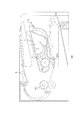
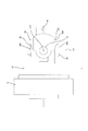
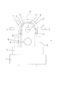
- FIG. 1 is a schematic diagram of an image forming apparatus according to the first embodiment.
- FIG. 2 is a schematic view of the developing cartridge.
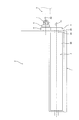
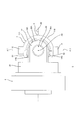
- FIG. 3 is a side view of the development coupling viewed from the second direction.
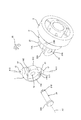
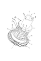
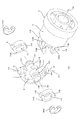
- FIG. 4 is an exploded perspective view of the development coupling.
- FIG. 5 is a side view of the development coupling as viewed from the third direction.
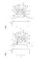
- FIG. 6A shows the development coupling in a state where the joint member is located at the first position.
- FIG. 6B shows the development coupling with the joint member positioned at the second position.
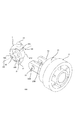
- FIG. 7 is an explanatory view for explaining the connection between the main body coupling and the development coupling.
- FIG. 1 is a schematic diagram of an image forming apparatus according to the first embodiment.
- FIG. 2 is a schematic view of the developing cartridge.
- FIG. 3 is a side view of the development coupling viewed from the second direction.
- FIG. 4 is an exploded perspective view of the development coupling.
- FIG. 5 is
- FIG. 8A is an explanatory diagram for explaining that the second joint member of the main body coupling is guided by the joint member of the developing coupling, and shows a case where the protruding portion of the joint member has a spherical shape.
- FIG. 8B is an explanatory diagram for explaining that the second joint member of the main body coupling is guided by the joint member of the developing coupling, and shows a case where the protruding portion of the joint member has a conical shape.
- FIG. 9 is a perspective view showing an example of the main body coupling.
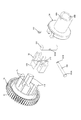
- FIG. 10 is an exploded perspective view of the universal joint.
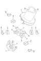
- FIG. 11 is an exploded perspective view showing the developing coupling of the second embodiment.
- FIG. 12 is an exploded perspective view showing the developing coupling of the third embodiment.
- FIG. 13 is an exploded perspective view showing the development coupling of the fourth embodiment.
- FIG. 14 is a side view of the development coupling of the fourth embodiment viewed from the third direction.
- FIG. 15 is an exploded perspective view showing the developing coupling of the fifth embodiment.
- FIG. 16 is a side view of the development coupling of the fifth embodiment viewed from the second direction.
- FIG. 17A shows a modification in which the joint member has a conical shape.
- FIG. 17B shows a modification in which the joint member has a protruding plate.
- FIG. 17C shows a modification in which the joint member has two plates that intersect and protrude from each other.
- FIG. 17D shows a modification in which the joint member has a protruding rod and a plate extending from the rod.
- FIG. 18 is an explanatory view illustrating a modified example of the main body coupling.
- FIG. 19 is an explanatory view illustrating a modification of the main body coupling.
- FIG. 20 is an ex
- the image forming apparatus 200 is an apparatus for forming an image on the paper S using a developer. Specifically, the image forming apparatus 200 is detachable from the developing cartridge 1 that stores the developer.
- the image forming apparatus 200 includes a photosensitive drum 201, a transfer roller 202, and a fixing device 203. On the surface of the photosensitive drum 201, a developer is supplied from the developing cartridge 1, and a developer image is formed.
- the transfer roller 202 transfers the developer image formed on the surface of the photosensitive drum 201 onto the paper S.
- the fixing device 203 fixes the developer image transferred to the paper S to the paper S by heating.
- the image forming apparatus 200 may be a monochrome printer capable of forming only a single color (monochrome) image or a color printer capable of forming a multicolor (color) image.
- the image forming apparatus 200 includes a main body coupling 8 for inputting a driving force to the developing cartridge 1 as shown in FIG.
- the main body coupling 8 will be described in detail later.
- an outline of the developing cartridge 1 will be described.
- the developing cartridge 1 includes a housing 2, a developing roller 3, a developing roller gear 4, and a developing coupling 5.
- the developing roller 3 is rotatable about a first axis A1 extending in the first direction.
- the housing 2 extends in the first direction.
- the housing 2 can accommodate a developer.
- the developer is, for example, toner.
- the side in which the developer is accommodated is the inside of the housing 2.
- the side opposite to the inside where the developer is accommodated is the outside of the housing 2.
- the housing 2 includes an outer surface 2A and an outer surface 2B. The outer surface 2A and the outer surface 2B are separated from each other in the first direction.
- the developing roller 3 is located at one end of the housing 2. A part of the peripheral surface of the developing roller 3 is exposed to the outside of the housing 2.
- the developing roller 3 includes a developing roller shaft 3A and a developing roller main body 3B.
- the developing roller shaft 3A extends along the first axis A1. One end of the developing roller shaft 3A in the first direction passes through the outer surface 2A.
- the developing roller main body 3B extends in the first direction.
- the developing roller body 3B has a cylindrical shape and covers the periphery of the developing roller shaft 3A.
- the developing roller main body 3B can rotate together with the developing roller shaft 3A.
- the developing roller shaft 3A may pass through the developing roller body 3B in the first direction.
- the developing roller shaft 3A may not penetrate the developing roller main body 3B in the first direction.
- the developing roller shaft 3A may separately have a shaft extending from one end portion of the developing roller main body portion 3B and a shaft extending from the other end portion of the developing roller main body portion 3B in the first direction. .
- the developing roller gear 4 is located outside the housing 2 in the first direction. Specifically, the developing roller gear 4 is located on the outer surface 2A. The developing roller gear 4 is located at one end of the developing roller 3 in the first direction. Specifically, the developing roller gear 4 is attached to one end of the developing roller shaft 3A in the first direction. The developing roller gear 4 can rotate together with the developing roller shaft 3A.
- the developing roller gear 4 has a plurality of gear teeth. The plurality of gear teeth are provided on the peripheral surface of the developing roller gear 4 along the rotation direction of the developing roller gear 4.
- the development coupling 5 is located outside the housing 2 in the first direction. Specifically, the development coupling 5 is located on the outer surface 2A. The development coupling 5 is rotatable about a second axis A2 extending in the first direction.
- the development coupling 5 includes a coupling gear 6 and a joint member 7.
- the coupling gear 6 can rotate about the second axis A2 together with the development coupling 5.
- the coupling gear 6 is located between the housing 2 and the joint member 7 in the first direction.
- the coupling gear 6 has a plurality of gear teeth.
- the plurality of gear teeth are provided on the peripheral surface of the coupling gear 6 along the rotation direction of the coupling gear 6.
- the coupling gear 6 meshes with the developing roller gear 4. Specifically, at least one gear tooth of the plurality of gear teeth of the coupling gear 6 and at least one gear tooth of the plurality of gear teeth of the developing roller gear 4 mesh with each other.
- the joint member 7 is configured to receive a driving force from the image forming apparatus 200.
- the joint member 7 is located on the opposite side of the housing 2 with respect to the coupling gear 6 in the first direction. In other words, the joint member 7 is located on the opposite side of the developing roller 3 with respect to the coupling gear 6 in the first direction.
- the joint member 7 can rotate together with the coupling gear 6.
- the joint member 7 can be connected to the main body coupling 8 of the image forming apparatus 200.
- the joint member 7 can receive a driving force from the main body coupling 8 by being connected to the main body coupling 8.
- the joint member 7 can rotate together with the main body coupling 8 by receiving a driving force from the main body coupling 8.
- the development coupling 5 includes a first bearing 22, a second bearing 23 and a shaft 24 in addition to the joint member 7 and the coupling gear 6 described above, as shown in FIGS. 3 and 4.
- the joint member 7 can pivot about the shaft 24 with respect to the coupling gear 6.
- the joint member 7 can pivot with respect to the coupling gear 6 about the third axis A3 from which the shaft 24 extends.
- First bearing 22 and second bearing 23 The first bearing 22 receives one end of a shaft 24 described later in the second direction.
- the second bearing 23 receives the other end portion of the shaft 24 described later in the second direction.
- the first bearing 22 and the second bearing 23 face each other in the second direction, and the second bearing 23 is located away from the first bearing 22 in the second direction.
- a part of the joint member 7 is located between the first bearing 22 and the second bearing 23 in the second direction.
- the first bearing 22 and the second bearing 23 can rotate together with the coupling gear 6.
- the first bearing 22 and the second bearing 23 are located on the opposite side of the developing roller 3 (see FIG. 2) with respect to the coupling gear 6 in the first direction.
- the first bearing 22 and the second bearing 23 are located on the opposite side of the outer surface 2A (see FIG. 2) with respect to the coupling gear 6 in the first direction.
- the first bearing 22 has a hole 22B.
- the hole 22B extends in the second direction.
- the hole 22B penetrates the first bearing 22 in the second direction.
- a shaft 24 described later is inserted into the hole 22B. Thereby, the 1st bearing 22 receives the one end part of the shaft 24 mentioned later.
- the second bearing 23 has a hole 23B.
- the hole 23B extends in the second direction.
- the hole 23B penetrates the second bearing 23 in the second direction.
- a shaft 24 described later is inserted into the hole 23B.
- the 2nd bearing 23 receives the other end part of the shaft 24 mentioned later.
- at least a part of the hole 22B overlaps at least a part of the hole 23B in the second direction.
- Any one of the hole 22B and the hole 23B may be a through hole.
- the development coupling 5 further includes a cylindrical portion 21.
- the cylinder part 21 is located between the coupling gear 6 and the first bearing 22 in the first direction. Further, the cylindrical portion 21 is located between the coupling gear 6 and the second bearing 23 in the first direction.
- the cylindrical portion 21 extends from the end surface of the coupling gear 6 in the first direction.
- the first bearing 22 and the second bearing 23 extend from the cylindrical portion 21 in the first direction.
- the cylinder part 21 has a columnar shape extending in the first direction. The outer diameter of the cylindrical portion 21 is smaller than the outer diameter defined by the tip circle of the coupling gear 6.
- Joint Member 7 In the second direction, a part of the joint member 7 is sandwiched between the first bearing 22 and the second bearing 23.
- the joint member 7 has a through hole 16.
- the through hole 16 extends in the second direction and penetrates the joint member 7 in the second direction.
- a shaft 24 is inserted into the through hole 16.
- at least a part of the through hole 16 is at least one of the holes 22B in the second direction. Overlapping the part.
- at least a part of the through hole 16 has a hole 23B in the second direction.
- the joint member 7 includes an outer surface S11 and an outer surface S12.
- the outer surface S11 is an outer surface on one side of the joint member 7 in the second direction.
- the outer surface S12 is an outer surface on the other side of the joint member 7 in the second direction, and the outer surface S12 is separated from the outer surface S11 in the second direction.
- the outer surface S11 faces the first bearing 22, and the outer surface S12 is the second surface. It faces the bearing 23.
- the shaft 24 extends along the second direction.
- the shaft 24 has a head 24A at one end in the second direction.
- the shaft 24 has a groove 24B at the other end in the second direction.
- the outer diameter of the head 24 ⁇ / b> A is larger than the outer diameter of the shaft 24.
- the outer diameter of the head 24A is larger than the inner diameter of the hole 22B. Therefore, the head 24A faces the first bearing 22 in a state where the shaft 24 is inserted into each of the hole 22B, the through hole 16, and the hole 23B.
- the groove 24 ⁇ / b> B is located at the other end of the shaft 24.
- the groove 24 ⁇ / b> B is recessed from the peripheral surface of the shaft 24 in the radial direction of the shaft 24.
- the groove 24 ⁇ / b> B extends along the circumferential direction of the shaft 24. In a state where the shaft 24 is inserted into each of the hole 22B, the through hole 16, and the hole 23B, the groove 24B is located on the opposite side of the head 24A with respect to the first bearing 22 and the second bearing 23. .
- the joint member 7 further includes a stopper 25.
- the stopper 25 In a state where the shaft 24 is inserted into each of the hole 22B, the through hole 16, and the hole 23B, the stopper 25 is fitted into the groove 24B.
- the stopper 25 faces the second bearing 23 in the second direction. . For this reason, the stopper 25 prevents the shaft 24 from coming out of the hole 22B, the through hole 16, and the hole 23B.
- the joint member 7 In a state where the shaft 24 is inserted into each of the hole 22B, the through hole 16, and the hole 23B and the stopper 25 is fitted in the groove 24B, the joint member 7 is spaced apart from the cylindrical portion 21. Yes. Therefore, as shown in FIGS. 6A and 6B, the joint member 7 can pivot about the shaft 24 with respect to the first bearing 22 and the second bearing 23.
- joint member 7 can pivot with respect to the first bearing 22 and the second bearing 23 between the first position shown in FIG. 6A and the second position shown in FIG. 6B with respect to the shaft 24.
- the tip of the first bearing 22 further includes an arc surface 22A.
- the tip of the second bearing 23 is provided with an arc surface 23A.
- the joint member 7 includes an arc surface 14A. A part of the joint member 7 is located between the first bearing 22 and the second bearing 23 in the second direction, and the shaft 24 is inserted into each of the hole 22B, the through hole 16, and the hole 23B. In this state, the arc surface 14A extends along the arc surface 22A of the first bearing 22, and the arc surface 14A is spaced apart from the arc surface 22A of the first bearing 22.
- the circular arc surface 14 ⁇ / b> A can pivot the joint member 7 between the first position and the second position with respect to the shaft 24 without contacting the first bearing 22.
- the circular arc surface 14A includes one end portion 14B and the other end portion 14C.
- the other end portion 14 ⁇ / b> C can stop the joint member 7 at the second position.
- a part of the joint member 7 is located between the first bearing 22 and the second bearing 23 in the second direction, and the shaft 24 includes the hole 22B, the through hole 16, and the hole 23B.
- the joint member 7 includes a circular arc surface (not shown).
- An arc surface (not shown) is aligned with the arc surface 14A in the second direction.
- An arc surface (not shown) has the same shape as the arc surface 14A.
- a part of the joint member 7 is located between the first bearing 22 and the second bearing 23 in the second direction, and the shaft 24 is inserted into each of the hole 22B, the through hole 16, and the hole 23B.
- an arc surface (not shown) extends along the arc surface 23 ⁇ / b> A of the second bearing 23.
- a circular arc surface (not shown) is spaced apart from the circular arc surface 23A of the second bearing 23.
- the joint member 7 includes a first protrusion 12 and a second protrusion 13.
- the first protrusion 12 extends in the radial direction of the coupling gear 6.
- the direction in which the first protrusion 12 extends is referred to as a first radial direction.
- the second protrusion 13 extends in the radial direction of the coupling gear 6.
- the direction in which the second protrusion 13 extends is referred to as a second radial direction.
- the second radial direction is a direction opposite to the first radial direction.
- the second protrusion 13 is separated from the first protrusion 12 in the radial direction of the coupling gear 6. More specifically, the first protrusion 12 extends from the joint member 7 in the first radial direction.
- the first protrusion 12 is located on the first outer surface S1 of the joint member 7 in the first radial direction and extends from the first outer surface S1.
- the second protrusion 13 extends from the joint member 7 in the second radial direction. That is, the second protrusion 13 is located on the second outer surface S2 of the joint member 7 in the second radial direction and extends from the second outer surface S2.
- the first protrusion 12 has a cylindrical shape.
- the second protrusion 13 has a cylindrical shape.
- the central axis A12 of the second protrusion 13 preferably coincides with the central axis A11 of the first protrusion 12.
- the first radial direction intersects with the second direction.
- the second radial direction intersects with the second direction. More specifically, the first radial direction intersects the second direction and further intersects the first direction.
- the second radial direction intersects the second direction and further intersects the first direction.
- the first radial direction may be orthogonal to the second direction.
- the second radial direction may be orthogonal to the second direction. More specifically, the first radial direction is orthogonal to the second direction and further orthogonal to the first direction. Further, the second radial direction is orthogonal to the second direction and further orthogonal to the first direction.
- the developing coupling 5 When the developing coupling 5 is connected to the main body coupling 8, the first protrusion 12 and the second protrusion 13 can be engaged with the main body coupling 8. Further, the first protrusion 12 and the second protrusion 13 are rotatable together with the development coupling 5. For this reason, the development coupling 5 can be rotated in accordance with the rotation of the main body coupling 8.
- the joint member 7 includes a third outer surface 11A and a fourth outer surface 11B.
- the third outer surface 11 ⁇ / b> A is located between the first protrusion 12 and the second protrusion 13 in the radial direction of the coupling gear 6.
- the third outer surface 11A extends from the tip P of the joint member 7 in the first direction toward the first protrusion 12.
- the tip P is farthest from the coupling gear 6 in the first direction.
- the tip P is located on the opposite side of the developing roller 3 (see FIG. 2) with respect to the coupling gear 6 in the first direction. Further, the tip P is separated from the first protrusion 12 along the second axis A2.
- the third outer surface 11 ⁇ / b> A swells toward the radially outer side of the through hole 16.
- the fourth outer surface 11 ⁇ / b> B is located between the first protrusion 12 and the second protrusion 13 in the radial direction of the coupling gear 6.
- the fourth outer surface 11B extends from the tip P of the joint member 7 in the first direction toward the second protrusion 13. More specifically, the fourth outer surface 11B swells toward the radially outer side of the through hole 16.
- the third outer surface 11 ⁇ / b> A is curved from the tip P toward the first protrusion 12. Further, the fourth outer surface 11B is curved from the tip P toward the second protrusion 13.
- the main body coupling 8 is coupled to the development coupling 5 as shown in FIG. 7 along the curvature of the third outer surface 11A and the fourth outer surface 11B. More specifically, as shown in FIG. 8A, the main body coupling 8 may advance toward the developing coupling 5 while being inclined with respect to the developing coupling 5.
- the third outer surface 11 ⁇ / b> A guides a second joint member 34 of the main body coupling 8 described later toward the first protrusion 12. More specifically, the third outer surface 11 ⁇ / b> A guides a first recess 66 ⁇ / b> A of the main body coupling 8 described later toward the first protrusion 12.
- the fourth outer surface 11B guides a second joint member 34 of the main body coupling 8 described later toward the second protrusion 13. More specifically, the fourth outer surface 11 ⁇ / b> B guides the second recess 66 ⁇ / b> B of the main body coupling 8 toward the second protrusion 13.
- the third outer surface 11A guides the first recess 66A toward the first protrusion 12, and the fourth outer surface 11B guides the second recess 66B toward the second protrusion 13, whereby the main body for the developing coupling 5 is obtained.
- the inclination of the coupling 8 is corrected.
- the main body coupling 8 is connected to the joint member 7 in a state where the inclination of the main body coupling 8 with respect to the developing coupling 5 is corrected.
- the tip P of the joint member 7 is positioned between the first recess 66A and the second recess 66B as shown in FIG. 8A. It only has to be.
- the position of the first recess 66A is obtained by the following equation (1). Further, the position of the second recess 66B is obtained by the following formula (2). Further, the position of the tip P is obtained by the following equation (3).
- Formula (1) lm ⁇ sin ⁇ m ⁇ dm / 2 ⁇ cos ⁇ m
- Formula (2) lm ⁇ sin ⁇ m + dm / 2 ⁇ cos ⁇ m
- Formula (3) h + dt / 2 ⁇ 1 / cos (90 ° ⁇ ) ⁇ sin ⁇ t
- tip P of the coupling member 7 will be.
- the tip P does not interfere with the inner surface of the second joint member 34 when the following expression (4) is satisfied.
- lm is a length from the rotation center of the second joint member 34 of the main body coupling 8 described later to the tip of the second joint member 34.
- dm is the inner diameter of the hole 65.
- ⁇ m is the inclination of the second joint member 34.
- ⁇ m is an angle formed by the central axis A21 of the second joint member 34 and the second axis A2.
- dt is the diameter of a circle centered on the third axis A3.
- dt is the diameter of the third outer surface 11A and the fourth outer surface 11B.
- ⁇ t is the inclination of the joint member 7. Specifically, ⁇ t is an angle formed by a straight line connecting the tip P and the third axis A3 and the second axis A2. ⁇ 1 is an angle formed by the central axis A11 of the first protrusion 12 and the imaginary line I1. The imaginary line I1 passes through the third axis A3 and is orthogonal to the tangent line T1 in contact with the third outer surface 11A. h is the distance between the second axis A2 and the fourth axis A4.
- lm is 27.4 mm
- dm is, for example, 12 mm
- ⁇ m is, for example, 10 °
- dt is, for example, 10.8 mm
- ⁇ t is, for example, 20 °
- ⁇ 1 is, for example, 90 °
- h is, for example, 1 mm
- the value obtained by equation (1) is ⁇ 1.15 mm.
- the third outer surface 11A of the joint member 7 is a spherical surface.
- the tangent line in contact with the fourth outer surface 11B coincides with the tangent line T1.
- the virtual line that is orthogonal to the tangent line that contacts the fourth outer surface 11B and passes through the third axis A3 also coincides with the virtual line I1.
- An angle ⁇ 2 formed by the imaginary line I1 and the central axis A12 of the second protrusion 13 is 90 °, like the angle ⁇ 1. Therefore, the fourth outer surface 11B of the joint member 7 is also a spherical surface.
- required by Formula (2) will be 10.67 mm.
- required by Formula (3) will be 2.85 mm.
- tip P of the coupling member 7 is , Located between the first recess 66A and the second recess 66B. Thereby, 11 A of 3rd outer surfaces of the coupling member 7 can guide the 1st recessed part 66A.
- ⁇ m + ⁇ t is 30 ° and is smaller than ⁇ 1, so when the third outer surface 11A of the joint member 7 guides the first recess 66A when the above formula (4) is satisfied, the tip P is the second joint member 34. Does not interfere with the inner surface.
- lm is 27.4 mm
- dm is, for example, 12 mm
- ⁇ m is, for example, 10 °
- dt is, for example, 10.8 mm
- ⁇ t is, for example, 20 °
- ⁇ 1 is, for example, 45 °
- h is, for example, 1 mm
- the value obtained by equation (1) is ⁇ 1.15 mm.
- ⁇ 1 is 45 °
- the third outer surface 11A of the joint member 7 is a conical surface.
- the angle ⁇ 2 formed by the imaginary line I2 orthogonal to the tangent line T2 that is in contact with the fourth outer surface 11B and passing through the third axis A3 and the center axis A12 of the second protrusion 13 is the same as the angle ⁇ 1. It is. Therefore, the fourth outer surface 11B of the joint member 7 is also a conical surface. Moreover, the value calculated
- tip P of the coupling member 7 is , Located between the first recess 66A and the second recess 66B. Thereby, 11 A of 3rd outer surfaces of the coupling member 7 can guide the 1st recessed part 66A.
- ⁇ m + ⁇ t is 30 ° and is smaller than ⁇ 1, so when the third outer surface 11A of the joint member 7 guides the first recess 66A when the above formula (4) is satisfied, the tip P is the second joint member 34. Does not interfere with the inner surface.
- Each parameter of ⁇ t, ⁇ m, and h has a maximum value that can be allowed by each parameter. When ⁇ t is the maximum allowable value of ⁇ t, ⁇ m is the maximum allowable value of ⁇ m, and h is the maximum allowable value of h, equations (1), (2) and If the conditions respectively represented by Formula (3) are satisfy
- a universal joint can be constructed with the ring 8.
- the universal joint is a cardan joint. Details of the main body coupling 8 will be described below with reference to FIGS. 9 and 10.
- Body coupling 8 The development coupling 5 described above is connected to the main body coupling 8. Hereinafter, the main body coupling 8 will be described. As shown in FIG. 9, the main body coupling 8 includes a drive supply member 31 and a universal joint 30.
- the drive supply member 31 receives a driving force from the image forming apparatus 200 and can rotate about the fourth axis A4 extending in the first direction.
- the drive supply member 31 includes a gear part 41 and a shaft 42.
- the gear part 41 has a plurality of gear teeth.
- the plurality of gear teeth are provided on the peripheral surface of the gear portion 41 along the rotation direction of the drive supply member 31.
- the gear unit 41 rotates by receiving driving from the motor of the image forming apparatus 200.
- the shaft 42 extends in the first direction. Since the shaft 42 is attached to the universal joint 30 described later, the universal joint 30 can rotate together with the drive supply member 31. That is, the drive supply member 31 supplies a drive force for the universal joint 30 to rotate.
- the universal joint 30 includes a first joint member 32, a second joint member 33, a second joint member 34, four bearings, and a spring 36.
- the four bearings are specifically a bearing 35A, a bearing 35B, a bearing 35C, and a bearing 35D.
- the universal joint 30 is a cardan joint.
- the first joint member 32 has a through hole 44.
- the through hole 44 penetrates the first joint member 32 in the first direction. By attaching the shaft 42 to the through hole 44, the first joint member 32 can rotate together with the drive supply member 31.
- the second joint member 33 has a through hole 51.
- the through hole 51 penetrates the second joint member 33 in the first direction.
- the shaft 42 is inserted into the through hole 51.
- the second joint member 33 further includes four shafts.
- the four shafts are specifically a shaft 52A, a shaft 52B, a shaft 52C, and a shaft 52D.
- the shaft 52 ⁇ / b> A extends in the first radial direction of the through hole 51.
- the shaft 52 ⁇ / b> B extends in the second radial direction of the through hole 51.
- the second radial direction is the direction opposite to the first radial direction.
- the shaft 52 ⁇ / b> C extends in the third radial direction of the through hole 51.
- the shaft 52 ⁇ / b> D extends in the fourth radial direction of the through hole 51.
- the fourth radial direction is the direction opposite to the third radial direction.
- the third radial direction intersects the first radial direction.
- the third radial direction is orthogonal to the first radial direction.
- the fourth radial direction intersects the first radial direction.
- the fourth radial direction is orthogonal to the first radial direction.
- a bearing 35A is mounted on the shaft 52A.
- a bearing 35B is attached to the shaft 52B.
- the first joint member 32 is coupled to the second joint member 33 via the bearing 35A and the bearing 35B. For this reason, the second joint member 33 can rotate together with the first joint member 32. Further, the first joint member 32 can pivot with respect to the second joint member 33 with respect to the shaft 52A and the shaft 52B. That is, the first joint member 32 can pivot with respect to the second joint member 33 about the fifth axis A5 from which the shaft 52A and the shaft 52B extend. The fifth axis A5 extends in the second direction.
- a bearing 35C is mounted on the shaft 52C.
- a bearing 35D is mounted on the shaft 52D.
- the second joint member 34 is connected to the second joint member 33 via the bearing 35C and the bearing 35D.
- the second joint member 34 is rotatable together with the second joint member 33. That is, the universal joint 30 can rotate together with the second joint member 34.
- the second joint member 33 is pivotable with respect to the second joint member 34 with respect to the shaft 52C and the shaft 52D. That is, the second joint member 33 can pivot with respect to the second joint member 34 about the sixth axis A6 from which the shaft 52C and the shaft 52D extend.
- the sixth axis A6 extends in the third direction.
- the fifth axis A5 and the sixth axis A6 intersect.
- the fifth axis A5 and the sixth axis A6 are orthogonal.
- the first joint member 32 can pivot with respect to the second joint member 33 about the fifth axis A5 extending in the second direction, and the second joint member 33 can be connected to the second joint member 34.
- the universal joint 30 can function as an eccentric allowable joint.
- the second joint member 34 further includes a first recess 66A and a second recess 66B.
- the first protrusion 12 can be fitted into the first recess 66A.
- the second protrusion 13 can be fitted into the second recess 66B.
- the second joint member 34 is connected to the joint member 7, and the joint member 7 can rotate together with the second joint member 34.
- the second joint member 34 further includes a hole 65.
- the hole 65 is located between the first recess 66A and the second recess 66B.
- the hole 65 is recessed from the tip of the second joint member 34 toward the second joint member 33. As shown in FIG. 7, when the first protrusion 12 fits into the first recess 66A and the second protrusion 13 fits into the second recess 66B, the hole 65 is formed on the third outer surface 11A and the fourth outer surface 11B. accept.
- the spring 36 is located between the second joint member 34 and the drive supply member 31 in the first direction.
- One end of the spring 36 is fixed to the second joint member 34.
- the other end of the spring 36 is fixed to the drive supply member 31.
- the first protrusion 12 and the second protrusion 13 are fitted in the first recess 66A and the second recess 66B of the second joint member 34, respectively.
- the joint member 34 forms a second universal joint.
- the joint member 7 and the second joint member 34 can function as an eccentricity allowable joint.
- the developing coupling 5 can receive the driving force of the motor of the image forming apparatus 200 via the two eccentric allowable joints, and thus can be driven stably.
- the rotation axis of the drive supply member 31 specifically, the fourth axis A4
- the rotation axis of the coupling gear 6 specifically, the second axis A2 do not coincide.
- the coupling gear 6 can be stably rotated by the two eccentric allowable joints.
- the development coupling 5 since the development coupling 5 includes a part of components that form one universal joint, the image forming apparatus 200 does not need to include all of the components that configure one universal joint. Further, when the image forming apparatus includes all of the parts constituting one universal joint, there is a concern that the universal joint may hang down from the image forming apparatus. Since the development coupling 5 includes a part of the parts constituting one universal joint, the universal joint can be prevented from hanging from the image forming apparatus 200.
- a second embodiment of the development coupling 5 will be described with reference to FIG. In the description of the second embodiment, the same components as those of the development coupling 5 are denoted by the same reference numerals, and the description thereof is omitted.
- the through hole 16 of the joint member 7 has a D shape.
- a part of the inner surface of the through hole 16 is a flat surface 16B, and the remaining portion is a curved surface 16A.
- the shaft 24 has the same D-shaped cross section as the through hole 16. Accordingly, the joint member 7 can pivot about the third axis A3 together with the shaft 24 in a state where the shaft 24 is inserted into the hole 22B, the through hole 16 and the hole 23B.
- the joint member 7 has a through hole 92.
- the through hole 92 penetrates between the tip P and the through hole 16 in the first direction.
- the shaft 24 has a through hole 93.
- the through hole 93 penetrates the shaft 24 in the radial direction of the shaft 24.
- the through hole 93 faces the through hole 92 in the radial direction of the shaft 24 when the shaft 24 is inserted into the through hole 16.
- the stopper 91 is inserted into the through hole 92 and the through hole 93 in the radial direction of the shaft 24. Thereby, the stopper 91 prevents the shaft 24 from coming out of the through hole 16.
- the joint member 7 includes a first shaft 101 extending along the third axis A3 and a second shaft 102 extending along the third axis A3.
- the first shaft 101 and the second shaft 102 are configured integrally with the joint member 7.
- the first shaft 101 is located on one outer surface S11 of the joint member 7 in the second direction.
- the second shaft 102 is located on the other outer surface S12 of the joint member 7 in the second direction.
- the first shaft 101 extends from one outer surface S11 of the joint member 7 in the second direction.
- the second shaft 102 extends from the other outer surface S12 of the joint member 7 to the opposite side to the first shaft 101 in the second direction.
- the second shaft 102 is spaced from the first shaft 101 in the second direction.
- the first shaft 101 and the second shaft 102 each have a cylindrical shape.
- the first shaft 101 is inserted into the through hole 22 ⁇ / b> B of the first bearing 22, and the second shaft 102 is inserted into the through hole 23 ⁇ / b> B of the second bearing 23.
- the first bearing 22 receives the first shaft 101.
- the second bearing 23 receives the second shaft 102.
- the joint member 7 can pivot with respect to the coupling gear 6 with respect to the first shaft 101 and the second shaft 102. That is, the joint member 7 can pivot with respect to the coupling gear 6 about the third axis A3.
- a fourth embodiment of the development coupling 5 will be described with reference to FIGS. 13 and 14. In the description of the fourth embodiment, the same components as those of the development coupling 5 are denoted by the same reference numerals, and the description thereof is omitted.
- the joint member 7 includes a first shaft 111 extending along the third axis A3 and a third axis A3. And a second shaft 112 extending.
- the first shaft 111 and the second shaft 112 are configured integrally with the joint member 7.
- the first shaft 111 is located on one outer surface S11 of the joint member 7 in the second direction.
- the second shaft 112 is located on the other outer surface S12 of the joint member 7 in the second direction.
- the first shaft 111 extends from one outer surface S11 of the joint member 7 in the second direction.
- the second shaft 112 extends from the other outer surface S12 of the joint member 7 to the opposite side to the first shaft 111 in the second direction.
- the second shaft 112 is spaced from the first shaft 111 in the second direction.
- the first shaft 111 and the second shaft 112 have a cylindrical shape.
- the 1st shaft 111 and the 2nd shaft 112 each have the groove
- the development coupling 110 includes a first support part 114 and a second support part 115.
- the first support part 114 and the second support part 115 extend from the tubular part 21 toward the joint member 7 in the first direction.
- the first support part 114 and the second support part 115 are located at a distance from each other in the second direction.
- a part of the joint member 7 is sandwiched between the first support part 114 and the second support part 115.
- the first support part 114 has a through hole 114A.
- the through hole 114A penetrates the first support portion 114 in the second direction.
- the inner surface of the through hole 114A has two grooves 114B.
- the two grooves 114B are recessed to opposite sides in the third direction.
- Each of the two grooves 114B is recessed from the inner surface of the through hole 114A toward the outer surface of the first support portion 114 in the third direction.
- Each of the plurality of grooves 114B extends in the second direction.
- the second support part 115 has the same structure as the first support part 114.
- the second support portion 115 has a through hole 115A having the same shape as the through hole 114A.
- 1st bearing 113A is attached to the 1st support part 114.
- a second bearing 113 ⁇ / b> B is attached to the second support portion 115.
- the first bearing 113 ⁇ / b> A is fitted into the through hole 114 ⁇ / b> A of the first support portion 114.
- the first bearing 113A includes two stoppers 118.
- the two stoppers 118 respectively extend from the surface of the first bearing 113A to the opposite sides in the third direction.
- One of the two stoppers 118 fits into one of the two grooves 114B. Accordingly, the first bearing 113A is prevented from rotating with respect to the first support portion 114 while being fitted in the through hole 114A.
- the second bearing 113B is fitted in the through hole 115A in a state where the second bearing 113B is prevented from rotating with respect to the second support portion 115.
- the first bearing 113A is attached to the first support portion 114, and the second bearing 113B is attached to the second support portion 115, so that the first bearing 113A and the second bearing 113B can rotate together with the coupling gear 6. .
- the first bearing 113A has a through hole 117 that penetrates the first bearing 113A in the second direction.
- the second bearing 113B has a through hole 117 that penetrates the second bearing 113B in the second direction.
- the first shaft 111 is inserted into the through hole 117 of the first bearing 113A.
- the second shaft 112 is inserted into the through hole 117 of the second bearing 113B.
- the joint member 7 can pivot about the first shaft 111 and the second shaft 112 with respect to the coupling gear 6.
- the development coupling 110 has a stopper 119A and a stopper 119B.
- the stopper 119 ⁇ / b> A is fitted in the groove 116 of the first shaft 111.
- the stopper 119A faces the first bearing 113A in the second direction. Accordingly, the stopper 119A prevents the first bearing 113A from coming off the first shaft 111.
- the stopper 119B faces the second bearing 113B in the second direction and prevents the second bearing 113B from coming off the second shaft 112.
- the joint member 7 includes the first shaft 121 extending along the third axis A3 and the third axis A3, similarly to the development coupling 100 of the third embodiment.
- a second shaft 122 extending.
- the first shaft 121 and the second shaft 122 are configured integrally with the joint member 7. Specifically, the first shaft 121 is located on one outer surface S11 of the joint member 7 in the second direction.
- the second shaft 122 is located on the other outer surface S12 of the joint member 7 in the second direction.
- the first shaft 121 extends from one outer surface S11 of the joint member 7 in the second direction.
- the second shaft 122 extends from the other outer surface S12 of the joint member 7 to the opposite side to the first shaft 121 in the second direction.
- the second shaft 122 is spaced from the first shaft 121 in the second direction.
- the first shaft 121 and the second shaft 122 have a cylindrical shape.
- the development coupling 120 includes a support portion 125.
- the support portion 125 extends from the tube portion 21 toward the joint member 7 in the first direction.
- the support part 125 has one end part and the other end part in the second direction. The one end portion is located at a distance from the other end portion in the second direction.
- the support part 125 includes a recess 128, a recess (not shown), and a through hole (not shown).
- the recess 128 is located at one end of the support portion 125 in the second direction.
- the recess 128 is recessed from one end portion of the support portion 125 toward the other end portion in the second direction.
- a recess (not shown) is located at the other end of the support portion 125 in the second direction.
- a recess (not shown) is recessed from the other end portion of the support portion 125 toward the one end portion in the second direction.
- a through hole (not shown) penetrates the support portion 125 in the second direction.
- the first bearing 123 is attached to the recess 128.
- the first bearing 123 extends in the first direction.
- the first bearing 123 has one end and the other end in the first direction.
- One end portion is located farther from the coupling gear 6 than the other end portion in the first direction.
- One end part protrudes toward the joint member 7 from the support part 125 in the first direction.
- the other end fits into the recess 128.
- the first bearing 123 includes a first through hole 130.
- the first through hole 130 is located at the other end of the first bearing 123.
- the first through hole 130 penetrates the other end of the first bearing 123 in the second direction.
- the first through hole 130 faces a through hole (not shown) of the support portion 125 in a state where the other end portion of the first bearing 123 is fitted in the recess 128.
- the second bearing 124 is attached to a recess (not shown).
- the first through hole 130 of the second bearing 124 faces a through hole (not shown) of the support part 125 in a state where the other end of the second bearing 124 is fitted in a recess (not shown).
- the insertion member 126 extending in the second direction is inserted into the first through hole 130 of the first bearing 123, the first through hole 130 of the second bearing 124, and the through hole (not shown) of the support portion 125.
- the first bearing 123 and the second bearing 124 are attached to the support portion 125.
- the insertion member 126 is prevented by the stopper 129 from coming out of the first through hole 130 of the first bearing 123, the first through hole 130 of the second bearing 124, and the through hole (not shown) of the support portion 125. Yes.
- the first bearing 123 has a second through hole 131.
- the second through hole 131 is located at one end of the first bearing 123.
- the second through hole 131 passes through one end of the first bearing 123 in the second direction.
- the second bearing 124 also has a second through hole 131.
- the first shaft 121 is inserted into the second through hole 131 of the first bearing 123. As a result, the first shaft 121 is received by the first bearing 123.
- the second shaft 122 is inserted into the second through hole 131 of the second bearing 124. As a result, the second shaft 122 is received by the second bearing 124.
- the joint member 7 can pivot about the first shaft 121 and the second shaft 122 with respect to the coupling gear 6.
- the joint member 7 described above has a spherical shape, but the shape of the joint member 7 may be a conical shape as shown in FIG. 17A, for example.
- the joint member 7 may have a plate 140 that protrudes in the first direction, as shown in FIGS. 17B and 17C.
- the joint member 7 may include a rod 141 protruding in the first direction and a plate 142 extending in the radial direction of the rod 141, as shown in FIG. 17D.
- the first bearing 22 and the second bearing 23 described above receive the shaft 24 by inserting the shaft 24 into the through hole 22B and the through hole 23B. Not limited to holes.
- the first bearing 22 and the second bearing 23 may have a recess that can receive the end of the shaft 24.
- the main body coupling 8 includes a stopper 152A that prevents the bearing 151A from coming off the shaft 52A, a stopper 152B that prevents the bearing 151B from coming off the shaft 52B, and a bearing 151C that comes off the shaft 52C.
- a stopper 152C for preventing and a stopper 152D for preventing the bearing 151D from coming off the shaft 52D may be provided.
- the drive supply member 31 may have two first protrusions 171 and two second protrusions 172 instead of the shaft 42.
- the two first projecting portions 171 project from the gear portion 41 toward the second joint member 7 in the first direction.
- the two first protrusions 171 are spaced apart from each other in the second direction.
- the two second protrusions 172 are located at a distance from the two first protrusions 171 in the third direction.
- the two second projecting portions 172 project from the gear portion 41 toward the second joint member 7 in the first direction.
- the two second protrusions 172 are spaced from each other in the second direction.
- the first joint member 32 includes a protrusion 170 that fits between the two first protrusions 171 and a protrusion 170 that fits between the two second protrusions 172. As a result, the first joint member 32 can rotate together with the drive supply member 31.
- the main body coupling 8 may include a first shaft 161 and a second shaft 162 penetrating the first shaft 161 instead of the second joint member 33.
- the first shaft 161 extends along the sixth axis A6.
- the first shaft 161 has a cylindrical shape.
- the first shaft 161 has a first through hole 161A.
- 161 A of 1st through-holes are located in the center of the 1st shaft 161 in a 3rd direction.
- the first through hole 161A penetrates the first shaft 161 in the second direction.
- the second shaft 162 extends along the fifth axis A5.
- the second shaft 162 has a cylindrical shape.
- the second shaft 162 is inserted into the first through hole 161 ⁇ / b> A of the first shaft 161.
- the second joint member 34 may be attached to the first shaft 161, and the first joint member 32 may be attached to the second shaft 162.
- the second joint member 34 is pivotable about the sixth axis A6 by being attached to the first shaft 161.
- the first joint member 32 can be pivoted about the fifth axis A5 by being attached to the second shaft 162.
- the universal joint 30 provided with the 1st shaft 161 and the 2nd shaft 162 can function as an eccentric allowable joint.
- the second shaft 162 may have a head 181A at one end in the second direction and a groove 181B at the other end in the second direction.
- the head 181 ⁇ / b> A faces the first joint member 32 in the second direction when the first joint member 32 is attached to the second shaft 162.
- a stopper 182 fits in the groove 181B on the opposite side of the head 181A with respect to the first joint member 32 in the second direction.
- the stopper 182 faces the first joint member 32 in the second direction.
- the head 181 ⁇ / b> A and the stopper 182 sandwich the first joint member 32 in the second direction, thereby preventing the first joint member 32 from coming off the second shaft 162.
Landscapes
- Engineering & Computer Science (AREA)
- General Engineering & Computer Science (AREA)
- Physics & Mathematics (AREA)
- General Physics & Mathematics (AREA)
- Mechanical Engineering (AREA)
- Electrophotography Configuration And Component (AREA)
- Dry Development In Electrophotography (AREA)
Abstract
ジョイントを構成する一部品を有する現像カートリッジおよび画像形成装置を提供する。 現像カートリッジ1は、現像ローラ3と、現像ローラ3と共に回転可能な現像ローラギア4と、現像ローラギア4と噛み合うカップリングギア6と、カップリングギア6と共に回転可能な継手部材7とを備える。継手部材7は、カップリングギア6の第1径方向に延びる第1突起12と、カップリングギア6の第2径方向であって、第1径方向と反対である第2径方向に延びる第2突起13とを備える。また、継手部材7は、カップリングギア6に対して、第1径方向および第2径方向と交差する方向に延びる第3軸A3についてピボット可能である。
Description
本開示は、現像カートリッジおよび画像形成装置に関する。
従来、現像カートリッジは、現像ローラと、画像形成装置から駆動力を受けるため、カップリングとを備える。カップリングが、画像形成装置からの駆動を受けることで、現像ローラは回転する。特許文献1には、画像形成装置が、現像駆動伝達部材を備えることが開示されている。現像駆動伝達部材は、現像駆動ギアと進退部材とを含む。そして、特許文献1の進退部材は、ユニバーサルジョイントを構成する。
本開示の目的は、ジョイントを構成する一部品を有する現像カートリッジおよび画像形成装置を提供することにある。
(1)本開示の現像カートリッジは、第1方向に延びる第1軸について回転可能な現像ローラと、第1方向において現像ローラの一端部に位置し、現像ローラと共に回転可能な現像ローラギアと、第1方向に延びる第2軸について回転可能なカップリングギアであって、現像ローラギアと噛み合うカップリングギアと、カップリングギアと共に回転可能であり、第1方向においてカップリングギアに対して、現像ローラの反対側に位置する継手部材とを備える。
継手部材は、カップリングギアの第1径方向に延びる第1突起と、第1突起とカップリングギアの径方向に離れた第2突起であって、カップリングギアの第2径方向であって、第1径方向と反対である第2径方向に延びる第2突起とを備える。
継手部材は、カップリングギアに対して、第1径方向および第2径方向と交差する第2方向に沿って延びる第3軸についてピボット可能である。
(2)第1突起は、第1径方向における継手部材の第1外表面に位置してもよい。第2突起は、第2径方向における継手部材の第2外表面に位置してもよい。
(3)第1突起は、第1外表面から延びてもよい。第2突起は、第2外表面から延びてもよい。
(4)第1径方向は、第2方向と直交してもよい。第2径方向は、第2方向と直交してもよい。
(5)現像カートリッジは、さらに、第2方向に沿って延びるシャフトと、カップリングギアと共に回転可能であり、第1方向においてカップリングギアに対して、現像ローラの反対側に位置する第1軸受であって、第2方向におけるシャフトの一端部を受ける第1軸受と、カップリングギアと共に回転可能であり、第1方向においてカップリングギアに対して、現像ローラの反対側に位置する第2軸受であって、第2方向において第1軸受と離れて位置し、第2方向におけるシャフトの他端部を受ける第2軸受とを備えてもよい。継手部材は、シャフトについてピボット可能であってもよい。
(6)継手部材は、第2方向に延びる貫通孔であって、シャフトが挿入される貫通孔を有してもよい。継手部材は、シャフトについてピボット可能であってもよい。
(7)継手部材は、さらに、第2方向に沿って延びる第1シャフトと、第2方向において、前記第1シャフトと反対側に延びる第2シャフトと、カップリングギアと共に回転可能であり、第1方向においてカップリングギアに対して、現像ローラの反対側に位置する第1軸受であって、第1シャフトを受ける第1軸受と、カップリングギアと共に回転可能であり、第1方向においてカップリングギアに対して、現像ローラの反対側に位置する第2軸受であって、第2方向において第1軸受と離れて位置し、第2シャフトを受ける第2軸受とを備えてもよい。継手部材は、第1シャフトと第2シャフトとについてピボット可能であってもよい。
(8)継手部材は、さらに、第2軸に沿って、第1突起から離れた先端であって、第1方向において、カップリングギアに対して現像ローラの反対側の先端から、第1突起に向けて延びる第3外表面と、先端から、第2突起に向けて延びる第4外表面とを少なくとも備えてもよい。
(9)第3外表面は、画像形成装置の第2継手部材を、第1突起に向けてガイドしてもよい。第4外表面は、第2継手部材を、第2突起に向けてガイドしてもよい。
(10)第3外表面および第4外表面は、球面であってもよい。
(11)第3外表面に接する接線に対して直交する仮想線であって、第3軸を通る仮想線と、第1突起の中心軸とがなす角度は、90°であってもよい。第4外表面に接する接線に対して直交する仮想線であって、第3軸を通る仮想線と、第2突起の中心軸とがなす角度は、90°であってもよい。
(12)第3外表面および第4外表面の径は、10.8mmであってもよい。
(13)現像カートリッジが着脱可能な画像形成装置であって、画像形成装置は、継手部材と接続され、継手部材と共に回転可能な第2継手部材であって、第1突起が嵌まる凹部と、第2突起が嵌まる凹部とを備える第2継手部材と、第1方向において第2継手部材に対して、継手部材の反対側に位置し、第2継手部材と共に回転可能なユニバーサルジョイントと、ユニバーサルジョイントが回転するための駆動力を供給する駆動供給部材とを備えてもよい。
(2)第1突起は、第1径方向における継手部材の第1外表面に位置してもよい。第2突起は、第2径方向における継手部材の第2外表面に位置してもよい。
(3)第1突起は、第1外表面から延びてもよい。第2突起は、第2外表面から延びてもよい。
(4)第1径方向は、第2方向と直交してもよい。第2径方向は、第2方向と直交してもよい。
(5)現像カートリッジは、さらに、第2方向に沿って延びるシャフトと、カップリングギアと共に回転可能であり、第1方向においてカップリングギアに対して、現像ローラの反対側に位置する第1軸受であって、第2方向におけるシャフトの一端部を受ける第1軸受と、カップリングギアと共に回転可能であり、第1方向においてカップリングギアに対して、現像ローラの反対側に位置する第2軸受であって、第2方向において第1軸受と離れて位置し、第2方向におけるシャフトの他端部を受ける第2軸受とを備えてもよい。継手部材は、シャフトについてピボット可能であってもよい。
(6)継手部材は、第2方向に延びる貫通孔であって、シャフトが挿入される貫通孔を有してもよい。継手部材は、シャフトについてピボット可能であってもよい。
(7)継手部材は、さらに、第2方向に沿って延びる第1シャフトと、第2方向において、前記第1シャフトと反対側に延びる第2シャフトと、カップリングギアと共に回転可能であり、第1方向においてカップリングギアに対して、現像ローラの反対側に位置する第1軸受であって、第1シャフトを受ける第1軸受と、カップリングギアと共に回転可能であり、第1方向においてカップリングギアに対して、現像ローラの反対側に位置する第2軸受であって、第2方向において第1軸受と離れて位置し、第2シャフトを受ける第2軸受とを備えてもよい。継手部材は、第1シャフトと第2シャフトとについてピボット可能であってもよい。
(8)継手部材は、さらに、第2軸に沿って、第1突起から離れた先端であって、第1方向において、カップリングギアに対して現像ローラの反対側の先端から、第1突起に向けて延びる第3外表面と、先端から、第2突起に向けて延びる第4外表面とを少なくとも備えてもよい。
(9)第3外表面は、画像形成装置の第2継手部材を、第1突起に向けてガイドしてもよい。第4外表面は、第2継手部材を、第2突起に向けてガイドしてもよい。
(10)第3外表面および第4外表面は、球面であってもよい。
(11)第3外表面に接する接線に対して直交する仮想線であって、第3軸を通る仮想線と、第1突起の中心軸とがなす角度は、90°であってもよい。第4外表面に接する接線に対して直交する仮想線であって、第3軸を通る仮想線と、第2突起の中心軸とがなす角度は、90°であってもよい。
(12)第3外表面および第4外表面の径は、10.8mmであってもよい。
(13)現像カートリッジが着脱可能な画像形成装置であって、画像形成装置は、継手部材と接続され、継手部材と共に回転可能な第2継手部材であって、第1突起が嵌まる凹部と、第2突起が嵌まる凹部とを備える第2継手部材と、第1方向において第2継手部材に対して、継手部材の反対側に位置し、第2継手部材と共に回転可能なユニバーサルジョイントと、ユニバーサルジョイントが回転するための駆動力を供給する駆動供給部材とを備えてもよい。
本開示によれば、ジョイントを構成する一部品を有する現像カートリッジおよび画像形成装置を提供することができる。
[第1実施形態]
1.画像形成装置200の概略
図1を参照して、画像形成装置200の概略について説明する。
1.画像形成装置200の概略
図1を参照して、画像形成装置200の概略について説明する。
画像形成装置200は、現像剤を用いて、用紙Sに画像を形成するための装置である。具体的には、画像形成装置200は、現像剤を収容する現像カートリッジ1を着脱可能である。
また、画像形成装置200は、感光ドラム201と、転写ローラ202と、定着器203とを備える。感光ドラム201の表面には、現像カートリッジ1から現像剤が供給され、現像剤像が形成される。転写ローラ202は、感光ドラム201の表面に形成された現像剤像を、用紙Sに転写する。定着器203は、用紙Sに転写された現像剤像を、加熱により、用紙Sに定着する。なお、画像形成装置200は、単色(モノクロ)の画像のみを形成可能なモノクロプリンタであってもよく、多色(カラー)の画像を形成可能なカラープリンタであってもよい。
また、画像形成装置200は、図2に示すように、現像カートリッジ1に駆動力を入力するための本体カップリング8を備える。本体カップリング8については後で詳しく説明する。以下、現像カートリッジ1の概略について説明する。
現像カートリッジ1は、筐体2と、現像ローラ3と、現像ローラギア4と、現像カップリング5とを備える。現像ローラ3は、第1方向に延びる第1軸A1について回転可能である。
1.1 筐体2
筐体2は、第1方向に延びる。筐体2は、現像剤を収容可能である。現像剤は、例えば、トナーである。なお、以下の説明において、筐体2の内側および外側に言及するときは、現像剤が収容される側が、筐体2の内側である。また、現像剤が収容される内側と反対側が、筐体2の外側である。筐体2は、外表面2Aと、外表面2Bとを備える。外表面2Aと外表面2Bとは、第1方向において互いに離れている。
筐体2は、第1方向に延びる。筐体2は、現像剤を収容可能である。現像剤は、例えば、トナーである。なお、以下の説明において、筐体2の内側および外側に言及するときは、現像剤が収容される側が、筐体2の内側である。また、現像剤が収容される内側と反対側が、筐体2の外側である。筐体2は、外表面2Aと、外表面2Bとを備える。外表面2Aと外表面2Bとは、第1方向において互いに離れている。
1.2 現像ローラ3
現像ローラ3は、筐体2の一端部に位置する。現像ローラ3の周面の一部は、筐体2の外側に露出している。現像ローラ3は、現像ローラシャフト3Aと、現像ローラ本体部3Bとを備える。現像ローラシャフト3Aは、第1軸A1に沿って延びる。第1方向における現像ローラシャフト3Aの一端部は、外表面2Aを貫通している。現像ローラ本体部3Bは、第1方向に延びる。現像ローラ本体部3Bは、円柱形状を有し、現像ローラシャフト3Aの周囲を覆う。現像ローラ本体部3Bは、現像ローラシャフト3Aとともに回転可能である。なお、現像ローラシャフト3Aは、第1方向において、現像ローラ本体部3Bを貫通してもよい。また、現像ローラシャフト3Aは、第1方向において、現像ローラ本体部3Bを貫通していなくてもよい。現像ローラシャフト3Aは、第1方向において、現像ローラ本体部3Bの一方の端部から延びるシャフトと、現像ローラ本体部3Bの他方の端部から延びるシャフトとを、別々に有していてもよい。
現像ローラ3は、筐体2の一端部に位置する。現像ローラ3の周面の一部は、筐体2の外側に露出している。現像ローラ3は、現像ローラシャフト3Aと、現像ローラ本体部3Bとを備える。現像ローラシャフト3Aは、第1軸A1に沿って延びる。第1方向における現像ローラシャフト3Aの一端部は、外表面2Aを貫通している。現像ローラ本体部3Bは、第1方向に延びる。現像ローラ本体部3Bは、円柱形状を有し、現像ローラシャフト3Aの周囲を覆う。現像ローラ本体部3Bは、現像ローラシャフト3Aとともに回転可能である。なお、現像ローラシャフト3Aは、第1方向において、現像ローラ本体部3Bを貫通してもよい。また、現像ローラシャフト3Aは、第1方向において、現像ローラ本体部3Bを貫通していなくてもよい。現像ローラシャフト3Aは、第1方向において、現像ローラ本体部3Bの一方の端部から延びるシャフトと、現像ローラ本体部3Bの他方の端部から延びるシャフトとを、別々に有していてもよい。
1.3 現像ローラギア4
現像ローラギア4は、第1方向において、筐体2の外側に位置する。具体的には、現像ローラギア4は、外表面2Aに位置する。現像ローラギア4は、第1方向において、現像ローラ3の一端部に位置する。詳しくは、現像ローラギア4は、第1方向において、現像ローラシャフト3Aの一端部に装着される。現像ローラギア4は、現像ローラシャフト3Aとともに回転可能である。現像ローラギア4は、複数のギア歯を有する。複数のギア歯は、現像ローラギア4の回転方向に沿って、現像ローラギア4の周面に設けられる。
現像ローラギア4は、第1方向において、筐体2の外側に位置する。具体的には、現像ローラギア4は、外表面2Aに位置する。現像ローラギア4は、第1方向において、現像ローラ3の一端部に位置する。詳しくは、現像ローラギア4は、第1方向において、現像ローラシャフト3Aの一端部に装着される。現像ローラギア4は、現像ローラシャフト3Aとともに回転可能である。現像ローラギア4は、複数のギア歯を有する。複数のギア歯は、現像ローラギア4の回転方向に沿って、現像ローラギア4の周面に設けられる。
1.4 現像カップリング5
現像カップリング5は、第1方向において、筐体2の外側に位置する。具体的には、現像カップリング5は、外表面2Aに位置する。現像カップリング5は、第1方向に延びる第2軸A2について回転可能である。現像カップリング5は、カップリングギア6と、継手部材7とを備える。
現像カップリング5は、第1方向において、筐体2の外側に位置する。具体的には、現像カップリング5は、外表面2Aに位置する。現像カップリング5は、第1方向に延びる第2軸A2について回転可能である。現像カップリング5は、カップリングギア6と、継手部材7とを備える。
カップリングギア6は、現像カップリング5と共に第2軸A2について回転可能である。カップリングギア6は、第1方向において、筐体2と継手部材7との間に位置する。カップリングギア6は、複数のギア歯を有する。複数のギア歯は、カップリングギア6の回転方向に沿って、カップリングギア6の周面に設けられる。カップリングギア6は、現像ローラギア4と噛み合う。具体的には、カップリングギア6の複数のギア歯の少なくとも1つのギア歯と、現像ローラギア4の複数のギア歯の少なくとも1つのギア歯とが噛み合う。
継手部材7は、画像形成装置200から駆動力を受けるための構成である。継手部材7は、第1方向において、カップリングギア6に対して筐体2の反対側に位置する。言い換えれば、継手部材7は、第1方向において、カップリングギア6に対して現像ローラ3の反対側に位置する。継手部材7は、カップリングギア6とともに回転可能である。後で詳述するが、継手部材7は、画像形成装置200の本体カップリング8に連結可能である。継手部材7は、本体カップリング8に連結することにより、本体カップリング8から駆動力を受けることができる。継手部材7は、本体カップリング8から駆動力を受けることにより、本体カップリング8とともに回転可能である。
2.現像カップリング5の詳細
次いで、図3から図6を参照して、現像カップリング5について、詳細に説明する。
次いで、図3から図6を参照して、現像カップリング5について、詳細に説明する。
現像カップリング5は、図3および図4に示すように、上記した継手部材7およびカップリングギア6に加え、第1軸受22、第2軸受23およびシャフト24を備える。第1軸受22、第2軸受23、および、シャフト24により、継手部材7は、カップリングギア6に対して、シャフト24についてピボット可能となる。言い換えれば、継手部材7は、カップリングギア6に対して、シャフト24が延びる第3軸A3についてピボット可能となる。以下、継手部材7、第1軸受22、第2軸受23、および、シャフト24の詳細を説明する。
2.1 第1軸受22および第2軸受23
第1軸受22は、第2方向において、後述するシャフト24の一端部を受ける。第2軸受23は、第2方向において、後述するシャフト24の他端部を受ける。第1軸受22と第2軸受23とは、第2方向において互いに向かい合い、第2軸受23は、第2方向において、第1軸受22と離れて位置する。詳細は後述するが、第2方向において、第1軸受22と第2軸受23との間に、継手部材7の一部が位置する。
第1軸受22は、第2方向において、後述するシャフト24の一端部を受ける。第2軸受23は、第2方向において、後述するシャフト24の他端部を受ける。第1軸受22と第2軸受23とは、第2方向において互いに向かい合い、第2軸受23は、第2方向において、第1軸受22と離れて位置する。詳細は後述するが、第2方向において、第1軸受22と第2軸受23との間に、継手部材7の一部が位置する。
第1軸受22および第2軸受23は、カップリングギア6とともに回転可能である。第1軸受22および第2軸受23は、第1方向において、カップリングギア6に対して、現像ローラ3(図2参照)の反対側に位置する。言い換えれば、第1軸受22および第2軸受23は、第1方向において、カップリングギア6に対して、外表面2A(図2参照)の反対側に位置する。
第1軸受22は、穴22Bを有する。なお、穴22Bは、第2方向に延びる。第1実施形態では、穴22Bは、第1軸受22を第2方向に貫通する。穴22Bに、後述するシャフト24が挿入される。これにより、第1軸受22は、後述するシャフト24の一端部を受ける。
第2軸受23は、穴23Bを有する。なお、穴23Bは、第2方向に延びる。第1実施形態では、穴23Bは、第2軸受23を第2方向に貫通する。穴23Bに、後述するシャフト24が挿入される。これにより、第2軸受23は、後述するシャフト24の他端部を受ける。さらに、穴22Bの少なくとも一部は、第2方向において、穴23Bの少なくとも一部に重なる。穴22Bと穴23Bとのいずれか一方が、貫通穴であれば良い。
2.2 筒部21
現像カップリング5は、さらに、筒部21を備える。筒部21は、第1方向において、カップリングギア6と、第1軸受22との間に位置する。また、筒部21は、第1方向において、カップリングギア6と、第2軸受23との間に位置する。筒部21は、カップリングギア6の第1方向における端面から延びる。第1軸受22および第2軸受23は、筒部21から第1方向に延びる。筒部21は、第1方向に延びる円柱形状を有する。筒部21の外径は、カップリングギア6の歯先円により定義される外径よりも小さい。
現像カップリング5は、さらに、筒部21を備える。筒部21は、第1方向において、カップリングギア6と、第1軸受22との間に位置する。また、筒部21は、第1方向において、カップリングギア6と、第2軸受23との間に位置する。筒部21は、カップリングギア6の第1方向における端面から延びる。第1軸受22および第2軸受23は、筒部21から第1方向に延びる。筒部21は、第1方向に延びる円柱形状を有する。筒部21の外径は、カップリングギア6の歯先円により定義される外径よりも小さい。
2.3 継手部材7の詳細
第2方向において、第1軸受22と第2軸受23との間に、継手部材7の一部が、挟まれる。継手部材7は、貫通穴16を有する。貫通穴16は、第2方向に延び、第2方向において、継手部材7を貫通する。貫通穴16には、シャフト24が挿入される。継手部材7の一部が、第2方向において、第1軸受22と第2軸受23との間に位置する状態において、貫通穴16の少なくとも一部は、第2方向において、穴22Bの少なくとも一部と重なる。また、継手部材7の一部が、第2方向において、第1軸受22と第2軸受23との間に位置する状態において、貫通穴16の少なくとも一部は、第2方向において、穴23Bの少なくとも一部と重なる。このため、シャフト24は、穴22B、貫通穴16、および、穴23Bにそれぞれ挿入される。より具体的には、継手部材7は、外表面S11と、外表面S12とを備える。外表面S11は、第2方向における継手部材7の一方側の外表面である。外表面S12は、第2方向における継手部材7の他方側の外表面であり、外表面S12は、第2方向において、外表面S11から離れている。継手部材7の一部が、第2方向において、第1軸受22と第2軸受23との間に位置する状態において、外表面S11は、第1軸受22と向かい合い、外表面S12は、第2軸受23と向かい合う。
第2方向において、第1軸受22と第2軸受23との間に、継手部材7の一部が、挟まれる。継手部材7は、貫通穴16を有する。貫通穴16は、第2方向に延び、第2方向において、継手部材7を貫通する。貫通穴16には、シャフト24が挿入される。継手部材7の一部が、第2方向において、第1軸受22と第2軸受23との間に位置する状態において、貫通穴16の少なくとも一部は、第2方向において、穴22Bの少なくとも一部と重なる。また、継手部材7の一部が、第2方向において、第1軸受22と第2軸受23との間に位置する状態において、貫通穴16の少なくとも一部は、第2方向において、穴23Bの少なくとも一部と重なる。このため、シャフト24は、穴22B、貫通穴16、および、穴23Bにそれぞれ挿入される。より具体的には、継手部材7は、外表面S11と、外表面S12とを備える。外表面S11は、第2方向における継手部材7の一方側の外表面である。外表面S12は、第2方向における継手部材7の他方側の外表面であり、外表面S12は、第2方向において、外表面S11から離れている。継手部材7の一部が、第2方向において、第1軸受22と第2軸受23との間に位置する状態において、外表面S11は、第1軸受22と向かい合い、外表面S12は、第2軸受23と向かい合う。
図4および図5に示すように、シャフト24は、第2方向に沿って延びる。シャフト24は、第2方向の一端部に頭部24Aを有する。また、シャフト24は、第2方向の他端部に溝24Bを有する。第2方向から見て、頭部24Aの外径は、シャフト24の外径よりも大きい。また、第2方向から見て、頭部24Aの外径は、穴22Bの内径よりも大きい。このため、シャフト24が、穴22B、貫通穴16、および、穴23Bのそれぞれに挿入された状態において、頭部24Aは、第1軸受22と向かい合う。溝24Bは、シャフト24の他端部に位置する。溝24Bは、シャフト24の径方向において、シャフト24の周面から凹む。溝24Bは、シャフト24の周方向に沿って延びる。シャフト24が、穴22B、貫通穴16、および、穴23Bのそれぞれに挿入された状態において、溝24Bは、第1軸受22および第2軸受23に対して、頭部24Aの反対側に位置する。
継手部材7は、さらに、ストッパ25を備える。シャフト24が、穴22B、貫通穴16、および、穴23Bのそれぞれに挿入された状態において、ストッパ25は、溝24Bに嵌まる。シャフト24が、穴22B、貫通穴16、および、穴23Bのそれぞれに挿入され、且つ、ストッパ25が、溝24Bに嵌った状態において、ストッパ25は、第2方向において、第2軸受23と向かい合う。このため、ストッパ25は、シャフト24が、穴22B、貫通穴16、および、穴23Bから抜けることを防ぐ。
シャフト24が、穴22B、貫通穴16、および、穴23Bのそれぞれに挿入され、且つ、ストッパ25が、溝24Bに嵌った状態において、継手部材7は、筒部21と間隔をあけて離れている。このため、図6Aおよび図6Bに示すように、継手部材7は、第1軸受22および第2軸受23に対して、シャフト24についてピボット可能となる。
さらに、継手部材7は、第1軸受22および第2軸受23に対して、シャフト24について、図6Aに示す第1位置と、図6Bに示す第2位置との間でピボット可能となる。
図6Aおよび図6Bに示すように、第1軸受22の先端は、さらに、円弧面22Aを備える。また、第2軸受23の先端は、円弧面23Aを備える。また、継手部材7は、円弧面14Aを備える。継手部材7の一部が、第2方向において、第1軸受22と第2軸受23との間に位置し、さらに、シャフト24が、穴22B、貫通穴16、および、穴23Bのそれぞれに挿入された状態において、円弧面14Aは、第1軸受22の円弧面22Aに沿って延び、円弧面14Aは、第1軸受22の円弧面22Aと間隔をあけて離れている。このため、円弧面14Aは、第1軸受22と接触することなく、継手部材7がシャフト24について第1位置と第2位置との間でピボットすることができる。さらに、円弧面14Aは、一端部14Bと、他端部14Cとを含む。継手部材7は、図6Bに示す第2位置から、図6Aに示す第1位置へピボットすると、一端部14Bは、第1軸受22と接触する。このため、一端部14Bは、継手部材7を第1位置で止めることができる。また、継手部材7は、図6Aに示す第1位置から、図6Bに示す第2位置へピボットすると、他端部14Cは、第1軸受22と接触する。このため、他端部14Cは、継手部材7を第2位置で止めることができる。また、継手部材7の一部が、第2方向において、第1軸受22と第2軸受23との間に位置し、さらに、シャフト24が、穴22B、貫通穴16、および、穴23Bのそれぞれに挿入された状態において、継手部材7が第1位置と第2位置との間でピボットするとき、継手部材7は、筒部21とは接触しない。なお、筒部21は、継手部材7の回転を止めるストッパとして用いてもよい。
同様に、継手部材7は、図示しない円弧面を備える。図示しない円弧面は、第2方向において、円弧面14Aと並ぶ。図示しない円弧面は、円弧面14Aと同じ形状を有する。継手部材7の一部が、第2方向において、第1軸受22と第2軸受23との間に位置し、さらに、シャフト24が、穴22B、貫通穴16、および、穴23Bのそれぞれに挿入された状態において、図示しない円弧面は、第2軸受23の円弧面23Aに沿って延びる。図示しない円弧面は、第2軸受23の円弧面23Aと間隔をあけて離れている。
以下、図3および図4を参照し、継手部材7が、本体カップリング8と連結するための構造について説明する。継手部材7は、第1突起12と、第2突起13とを備える。
第1突起12は、カップリングギア6の径方向に延びる。以下、第1突起12が延びる方向を、第1径方向とする。また、第2突起13は、カップリングギア6の径方向に延びる。以下、第2突起13が延びる方向を、第2径方向とする。第1実施形態では、第2径方向は、第1径方向と反対の方向である。第2突起13は、カップリングギア6の径方向において、第1突起12と離れている。より詳細には、第1突起12は、継手部材7から第1径方向に延びる。つまり、第1突起12は、第1径方向における継手部材7の第1外表面S1に位置し、第1外表面S1から延びる。また、第2突起13は、継手部材7から第2径方向に延びる。つまり、第2突起13は、第2径方向における継手部材7の第2外表面S2に位置し、第2外表面S2から延びる。第1突起12は、円柱形状を有する。また、第2突起13は、円柱形状を有する。第2突起13の中心軸A12は、好ましくは、第1突起12の中心軸A11と一致する。
なお、第1径方向は、第2方向と交差する。また、第2径方向は、第2方向と交差する。より詳しくは、第1径方向は、第2方向と交差し、さらに、第1方向と交差する。また、第2径方向は、第2方向と交差し、さらに、第1方向と交差する。
好ましくは、第1径方向は、第2方向と直交してもよい。また、第2径方向は、第2方向と直交してもよい。より詳しくは、第1径方向は、第2方向と直交し、さらに、第1方向と直交する。また、第2径方向は、第2方向と直交し、さらに、第1方向と直交する。
現像カップリング5が本体カップリング8に連結するときに、第1突起12および第2突起13は、本体カップリング8と係合可能である。また、第1突起12と、第2突起13とは、現像カップリング5と共に回転可能である。このため、本体カップリング8の回転に合わせて、現像カップリング5は回転することができる。
さらに、継手部材7は、第3外表面11Aと、第4外表面11Bとを備える。第3外表面11Aは、カップリングギア6の径方向において、第1突起12と第2突起13との間に位置する。第3外表面11Aは、第1方向における継手部材7の先端Pから、第1突起12へ向けて延びる。先端Pは、第1方向において、カップリングギア6から最も離れている。先端Pは、第1方向において、カップリングギア6に対して現像ローラ3(図2参照)の反対側に位置する。また、先端Pは、第2軸A2に沿って、第1突起12から離れている。さらに詳細には、第3外表面11Aは、貫通穴16の径方向外側に向けて膨らむ。第4外表面11Bは、カップリングギア6の径方向において、第1突起12と第2突起13との間に位置する。第4外表面11Bは、第1方向における継手部材7の先端Pから、第2突起13へ向けて延びる。さらに詳細には、第4外表面11Bは、貫通穴16の径方向外側に向けて膨らむ。このため、第3外表面11Aは、先端Pから第1突起12へ向けて湾曲する。また、第4外表面11Bは、先端Pから第2突起13へ向けて湾曲する。
本体カップリング8は、第3外表面11Aおよび第4外表面11Bの湾曲に沿って、図7に示すように、現像カップリング5に連結する。より詳細には、本体カップリング8は、図8Aに示すように、現像カップリング5に対して、傾いた状態で、現像カップリング5に向かって進出する場合がある。この場合に、第3外表面11Aは、後述する本体カップリング8の第2継手部材34を、第1突起12へ向けてガイドする。さらに詳しくは、第3外表面11Aは、後述する本体カップリング8の第1凹部66Aを、第1突起12へ向けてガイドする。また、第4外表面11Bは、後述する本体カップリング8の第2継手部材34を、第2突起13へ向けてガイドする。さらに詳しくは、第4外表面11Bは、本体カップリング8の第2凹部66Bを、第2突起13へ向けてガイドする。第3外表面11Aが第1凹部66Aを第1突起12へ向けてガイドし、第4外表面11Bが第2凹部66Bを第2突起13へ向けてガイドすることにより、現像カップリング5に対する本体カップリング8の傾きが、補正される。そして、本体カップリング8は、現像カップリング5に対する本体カップリング8の傾きが補正された状態で、継手部材7と連結する。
継手部材7の第3外表面11Aが第1凹部66Aをガイド可能となるには、図8Aに示すように、継手部材7の先端Pが、第1凹部66Aと第2凹部66Bとの間に位置していればよい。
第1凹部66Aの位置は、下記式(1)によって求められる。また、第2凹部66Bの位置は、下記式(2)によって求められる。また、先端Pの位置は、下記式(3)によって求められる。
式(1):lm×sinθm-dm/2×cosθm
式(2):lm×sinθm+dm/2×cosθm
式(3):h+dt/2×1/cos(90°-α)×sinθt
そして、上記式(3)で求められた値が、上記式(1)で求められた値よりも大きく、上記式(2)で求められた値よりも小さければ、継手部材7の先端Pは、第1凹部66Aと第2凹部66Bとの間に位置する。
式(2):lm×sinθm+dm/2×cosθm
式(3):h+dt/2×1/cos(90°-α)×sinθt
そして、上記式(3)で求められた値が、上記式(1)で求められた値よりも大きく、上記式(2)で求められた値よりも小さければ、継手部材7の先端Pは、第1凹部66Aと第2凹部66Bとの間に位置する。
また、継手部材7の第3外表面11Aが第1凹部66Aをガイドするときには、下記式(4)を満たす場合、先端Pが第2継手部材34の内面に干渉しない。
式(4):α>θm+θt
なお、式(1)から式(4)において、lmは、後述する本体カップリング8の第2継手部材34の回転中心から、第2継手部材34の先端までの長さである。dmは、穴65の内径である。θmは、第2継手部材34の傾きである。具体的には、θmは、第2継手部材34の中心軸A21と第2軸A2とがなす角度である。dtは、第3軸A3を中心とする円の径である。第3外表面11Aおよび第4外表面11Bが球面である場合には、dtは、第3外表面11Aおよび第4外表面11Bの径である。θtは、継手部材7の傾きである。具体的には、θtは、先端Pと第3軸A3とを結ぶ直線と、第2軸A2とがなす角度である。α1は、第1突起12の中心軸A11と仮想線I1とがなす角度である。仮想線I1は、第3軸A3を通り、第3外表面11Aに接する接線T1に対して直交する。hは、第2軸A2と第4軸A4との距離である。
なお、式(1)から式(4)において、lmは、後述する本体カップリング8の第2継手部材34の回転中心から、第2継手部材34の先端までの長さである。dmは、穴65の内径である。θmは、第2継手部材34の傾きである。具体的には、θmは、第2継手部材34の中心軸A21と第2軸A2とがなす角度である。dtは、第3軸A3を中心とする円の径である。第3外表面11Aおよび第4外表面11Bが球面である場合には、dtは、第3外表面11Aおよび第4外表面11Bの径である。θtは、継手部材7の傾きである。具体的には、θtは、先端Pと第3軸A3とを結ぶ直線と、第2軸A2とがなす角度である。α1は、第1突起12の中心軸A11と仮想線I1とがなす角度である。仮想線I1は、第3軸A3を通り、第3外表面11Aに接する接線T1に対して直交する。hは、第2軸A2と第4軸A4との距離である。
lmが、例えば、27.4mmであり、dmが、例えば、12mmであり、θmが、例えば、10°であり、dtが、例えば、10.8mmであり、θtが、例えば、20°であり、α1が、例えば、90°であり、hが、例えば、1mmである場合、式(1)で求められる値は、-1.15mmとなる。なお、α1が90°である場合には、継手部材7の第3外表面11Aは、球面となる。ここで、第4外表面11Bに接する接線は、接線T1と一致する。そのため、第4外表面11Bに接する接線に対して直交し、かつ、第3軸A3を通る仮想線も、仮想線I1と一致する。仮想線I1と、第2突起13の中心軸A12とがなす角度α2は、角度α1と同様に、90°である。そのため、継手部材7の第4外表面11Bも、球面となる。また、式(2)で求められる値は、10.67mmとなる。また、式(3)で求められる値は、2.85mmとなる。これにより、式(3)で求められた値が、上記式(1)で求められた値よりも大きく、上記式(2)で求められた値よりも小さいので、継手部材7の先端Pは、第1凹部66Aと第2凹部66Bとの間に位置する。これにより、継手部材7の第3外表面11Aは、第1凹部66Aをガイド可能となる。
また、θm+θtは、30°となり、α1よりも小さいので、上記式(4)を満たし、継手部材7の第3外表面11Aが第1凹部66Aをガイドするとき、先端Pが第2継手部材34の内面に干渉しない。
なお、図8Bに示すように、先端Pが突出している場合(図17Aから図17Dに示す変形例に相当する場合)も同様である。
具体的には、lmが、例えば、27.4mmであり、dmが、例えば、12mmであり、θmが、例えば、10°であり、dtが、例えば、10.8mmであり、θtが、例えば、20°であり、α1が、例えば、45°であり、hが、例えば、1mmである場合、式(1)で求められる値は、-1.15mmとなる。なお、α1が45°である場合には、継手部材7の第3外表面11Aは、円錐形状の表面となる。ここで、第4外表面11Bに接する接線T2に対して直交し、かつ、第3軸A3を通る仮想線I2と、第2突起13の中心軸A12とがなす角度α2は、角度α1と同じである。そのため、継手部材7の第4外表面11Bも、円錐形状の表面となる。また、式(2)で求められる値は、10.67mmとなる。また、式(3)で求められる値は、3.61mmとなる。これにより、式(3)で求められた値が、上記式(1)で求められた値よりも大きく、上記式(2)で求められた値よりも小さいので、継手部材7の先端Pは、第1凹部66Aと第2凹部66Bとの間に位置する。これにより、継手部材7の第3外表面11Aは、第1凹部66Aをガイド可能となる。
また、θm+θtは、30°となり、α1よりも小さいので、上記式(4)を満たし、継手部材7の第3外表面11Aが第1凹部66Aをガイドするとき、先端Pが第2継手部材34の内面に干渉しない。なお、θt、θm、および、hのそれぞれのパラメータは、各パラメータが許容できる最大値がある。θtが、θtの許容できる最大値であり、θmが、θmの許容できる最大値であり、さらに、hが、hの許容できる最大値であるときに、式(1)、式(2)および式(3)によりそれぞれ表される条件が満たされれば、継手部材7の第3外表面11Aが第1凹部66Aをガイド可能となる。
さらに、継手部材7がカップリングギア6に対してピボット可能であることにより、図7に示すように、現像カップリング5が本体カップリング8に連結したときに、現像カップリング5は、本体カップリング8とともにユニバーサルジョイントを構成することができる。詳しくは、ユニバーサルジョイントは、カルダンジョイントである。以下に、図9および図10を用いて、本体カップリング8の詳細を説明する。
3.本体カップリング8
上記した現像カップリング5は、本体カップリング8と連結される。以下、本体カップリング8について説明する。図9に示すように、本体カップリング8は、駆動供給部材31と、ユニバーサルジョイント30とを備える。
上記した現像カップリング5は、本体カップリング8と連結される。以下、本体カップリング8について説明する。図9に示すように、本体カップリング8は、駆動供給部材31と、ユニバーサルジョイント30とを備える。
駆動供給部材31は、画像形成装置200から駆動力を受けて、第1方向に延びる第4軸A4について回転可能である。駆動供給部材31は、ギア部41と、シャフト42を備える。
ギア部41は、複数のギア歯を有する。複数のギア歯は、駆動供給部材31の回転方向に沿って、ギア部41の周面に設けられる。ギア部41は、画像形成装置200のモータから駆動を受けることで回転する。シャフト42は、第1方向に延びる。シャフト42は、後述するユニバーサルジョイント30に装着されるため、ユニバーサルジョイント30は、駆動供給部材31と共に回転可能となる。つまり、駆動供給部材31は、ユニバーサルジョイント30が回転するための駆動力を供給する。
図10に示すように、ユニバーサルジョイント30は、第1ジョイント部材32、第2ジョイント部材33、第2継手部材34、4つのベアリング、および、ばね36を備える。4つのベアリングは、具体的には、ベアリング35A、ベアリング35B、ベアリング35Cおよびベアリング35Dである。ユニバーサルジョイント30は、すなわち、カルダンジョイントである。
第1ジョイント部材32は、貫通穴44を有する。貫通穴44は、第1ジョイント部材32を第1方向に貫通する。シャフト42が貫通穴44に装着されることで、第1ジョイント部材32は、駆動供給部材31と共に回転可能となる。
第2ジョイント部材33は、貫通穴51を有する。貫通穴51は、第2ジョイント部材33を第1方向に貫通する。貫通穴51には、シャフト42が挿入される。第2ジョイント部材33は、さらに、4つのシャフトを備える。4つのシャフトは、具体的には、シャフト52A、シャフト52B、シャフト52Cおよびシャフト52Dである。
シャフト52Aは、貫通穴51の第1径方向に延びる。シャフト52Bは、貫通穴51の第2径方向に延びる。第2径方向は、第1径方向と反対の方向である。また、シャフト52Cは、貫通穴51の第3径方向に延びる。シャフト52Dは、貫通穴51の第4径方向に延びる。第4径方向は、第3径方向と反対の方向である。なお、第1径方向に対して、第3径方向は交差する。好ましくは、第1径方向に対して、第3径方向は直交する。なお、第1径方向に対して、第4径方向は交差する。好ましくは、第1径方向に対して、第4径方向は直交する。
シャフト52Aには、ベアリング35Aが装着される。また、シャフト52Bには、ベアリング35Bが装着される。そして、第1ジョイント部材32は、ベアリング35Aおよびベアリング35Bを介して、第2ジョイント部材33に連結される。このため、第2ジョイント部材33は、第1ジョイント部材32と共に回転可能である。さらに、第1ジョイント部材32は、第2ジョイント部材33に対して、シャフト52Aおよびシャフト52Bについてピボット可能である。つまり、第1ジョイント部材32は、第2ジョイント部材33に対して、シャフト52Aおよびシャフト52Bが延びる第5軸A5についてピボット可能である。なお、第5軸A5は、第2方向に延びる。また、シャフト52Cには、ベアリング35Cが装着される。また、シャフト52Dには、ベアリング35Dが装着される。
第2継手部材34は、ベアリング35Cおよびベアリング35Dを介して、第2ジョイント部材33に連結される。
このため、第2継手部材34は、第2ジョイント部材33と共に回転可能である。すなわち、ユニバーサルジョイント30は、第2継手部材34とともに回転可能である。さらに、第2ジョイント部材33は、第2継手部材34に対して、シャフト52Cおよびシャフト52Dについてピボット可能である。つまり、第2ジョイント部材33は、第2継手部材34に対して、シャフト52Cおよびシャフト52Dが延びる第6軸A6についてピボット可能である。第6軸A6は、第3方向に延びる。第5軸A5と第6軸A6とは、交差する。好ましくは、第5軸A5と第6軸A6とは、直交する。このように、第1ジョイント部材32は、第2ジョイント部材33に対して、第2方向に延びる第5軸A5についてピボット可能であり、さらに、第2ジョイント部材33は、第2継手部材34に対して、第3方向に延びる第6軸A6についてピボット可能であるため、ユニバーサルジョイント30は、偏心許容継手として機能することができる。
第2継手部材34は、さらに、第1凹部66Aと、第2凹部66Bとを備える。第1突起12は、第1凹部66Aに嵌ることができる。また、第2突起13は、第2凹部66Bに嵌ることができる。このため、第2継手部材34は、継手部材7と連結し、継手部材7は、第2継手部材34と共に回転することができる。また、第2継手部材34は、さらに、穴65を備える。穴65は、第1凹部66Aと第2凹部66Bとの間に位置する。穴65は、第2継手部材34の先端から第2ジョイント部材33に向かって凹む。穴65は、図7に示すように、第1突起12が第1凹部66Aに嵌り、第2突起13が第2凹部66Bに嵌ったときに、第3外表面11Aおよび第4外表面11Bを受け入れる。
ばね36は、図9に示すように、第1方向において、第2継手部材34と、駆動供給部材31との間に位置する。ばね36の一端部は、第2継手部材34に固定される。ばね36の他端部は、駆動供給部材31に固定される。このため、第2継手部材34に継手部材7が連結される衝撃を和らげることができる。
これにより、第2継手部材34の、第1凹部66Aと第2凹部66Bとに、第1突起12と第2突起13とがそれぞれ嵌ることで、ユニバーサルジョイント30に加え、継手部材7と第2継手部材34とにより、2つ目のユニバーサルジョイントが構成される。そして、継手部材7と第2継手部材34とは、偏心許容継手として機能することができる。このため、現像カップリング5は、画像形成装置200のモータの駆動力を2つの偏心許容継手を介して受けることができるため、安定して駆動することができる。これにより、駆動供給部材31の回転軸(具体的には、第4軸A4)と、カップリングギア6の回転軸(具体的には、第2軸A2)とが一致しない場合であっても、2つの偏心許容継手により、カップリングギア6は安定して回転することができる。また、現像カップリング5が、1つのユニバーサルジョイントを構成する部品の一部を備えることで、画像形成装置200が1つのユニバーサルジョイントを構成する部品の全てを備える必要が無い。また、画像形成装置が1つのユニバーサルジョイントを構成する部品の全てを備える場合、画像形成装置からユニバーサルジョイントが垂れ下がる懸念がある。現像カップリング5が、1つのユニバーサルジョイントを構成する部品の一部を備えることで、画像形成装置200からユニバーサルジョイントが垂れ下がることを防ぐことができる。
[第2実施形態]
図11を参照して、現像カップリング5の第2実施形態について説明する。なお、第2実施形態の説明において、現像カップリング5と同様の構成には同様の符号を付し、その説明を省略する。
[第2実施形態]
図11を参照して、現像カップリング5の第2実施形態について説明する。なお、第2実施形態の説明において、現像カップリング5と同様の構成には同様の符号を付し、その説明を省略する。
第2実施形態の現像カップリング90では、継手部材7の貫通穴16は、D形状を有する。貫通穴16の内面は、一部が平面16Bであり、残りの部分が湾曲面16Aである。また、シャフト24は、貫通穴16と同じD形状の断面を有する。これにより、シャフト24が穴22B、貫通穴16および穴23Bに挿入された状態で、継手部材7は、シャフト24とともに、第3軸A3についてピボット可能となる。
また、継手部材7は、貫通穴92を有する。貫通穴92は、第1方向において、先端Pと貫通穴16との間を貫通する。また、シャフト24は、貫通穴93を有する。貫通穴93は、シャフト24の径方向において、シャフト24を貫通する。貫通穴93は、シャフト24が貫通穴16に挿入されたときに、シャフト24の径方向において、貫通穴92と向かい合う。ストッパ91は、シャフト24の径方向において、貫通穴92および貫通穴93に挿入される。これにより、ストッパ91は、シャフト24が貫通穴16から抜けることを防止する。
[第3実施形態]
図12を参照して、現像カップリング5の第3実施形態について説明する。なお、第3実施形態の説明において、現像カップリング5と同様の構成には同様の符号を付し、その説明を省略する。
[第3実施形態]
図12を参照して、現像カップリング5の第3実施形態について説明する。なお、第3実施形態の説明において、現像カップリング5と同様の構成には同様の符号を付し、その説明を省略する。
第3実施形態の現像カップリング100では、継手部材7は、第3軸A3に沿って延びる第1シャフト101と、第3軸A3に沿って延びる第2シャフト102とを有する。第1シャフト101および第2シャフト102は、継手部材7と一体的に構成される。詳しくは、第1シャフト101は、第2方向において、継手部材7の一方の外表面S11に位置する。第2シャフト102は、第2方向において、継手部材7の他方の外表面S12に位置する。第1シャフト101は、第2方向において、継手部材7の一方の外表面S11から延びる。第2シャフト102は、第2方向において、継手部材7の他方の外表面S12から、第1シャフト101と反対側へ延びる。第2シャフト102は、第2方向において、第1シャフト101に対して、間隔を隔てている。第1シャフト101および第2シャフト102は、それぞれ、円柱形状を有する。
そして、第1シャフト101が第1軸受22の貫通穴22Bに挿入され、第2シャフト102が第2軸受23の貫通穴23Bに挿入される。これにより、第1軸受22は、第1シャフト101を受ける。また、第2軸受23は、第2シャフト102を受ける。これにより、継手部材7は、カップリングギア6に対して、第1シャフト101および第2シャフト102についてピボット可能となる。つまり、継手部材7は、カップリングギア6に対して、第3軸A3についてピボット可能となる。
[第4実施形態]
図13および図14を参照して、現像カップリング5の第4実施形態について説明する。なお、第4実施形態の説明において、現像カップリング5と同様の構成には同様の符号を付し、その説明を省略する。
[第4実施形態]
図13および図14を参照して、現像カップリング5の第4実施形態について説明する。なお、第4実施形態の説明において、現像カップリング5と同様の構成には同様の符号を付し、その説明を省略する。
第4実施形態の現像カップリング110では、第3実施形態の現像カップリング100と同様に、継手部材7は、第3軸A3に沿って延びる第1シャフト111と、第3軸A3に沿って延びる第2シャフト112とを有する。第1シャフト111および第2シャフト112は、継手部材7と一体的に構成される。詳しくは、第1シャフト111は、第2方向において、継手部材7の一方の外表面S11に位置する。第2シャフト112は、第2方向において、継手部材7の他方の外表面S12に位置する。第1シャフト111は、第2方向において、継手部材7の一方の外表面S11から延びる。第2シャフト112は、第2方向において、継手部材7の他方の外表面S12から、第1シャフト111と反対側へ延びる。第2シャフト112は、第2方向において、第1シャフト111に対して、間隔を隔てている。第1シャフト111および第2シャフト112は、円柱形状を有する。また、第1シャフト111および第2シャフト112は、それぞれ、周面から凹む溝116を有する。
現像カップリング110は、第1支持部114と、第2支持部115とを備える。第1支持部114および第2支持部115は、第1方向において、筒部21から継手部材7に向かって延びる。第1支持部114と第2支持部115とは、第2方向において、互いに間隔を隔てて位置する。第1支持部114と第2支持部115との間には、継手部材7の一部が挟まれる。
第1支持部114は、貫通穴114Aを有する。貫通穴114Aは、第2方向において、第1支持部114を貫通する。貫通穴114Aの内面は、2つの溝114Bを有する。2つの溝114Bは、第3方向において、互いに反対側へ凹む。2つの溝114Bは、それぞれ、第3方向において、貫通穴114Aの内面から、第1支持部114の外面に向かって凹む。複数の溝114Bは、それぞれ、第2方向に延びる。第2支持部115は、第1支持部114と同じ構造を有する。第2支持部115は、貫通穴114Aと同じ形状の貫通穴115Aを有する。
第1支持部114には、第1軸受113Aが取り付けられる。第2支持部115には、第2軸受113Bが取り付けられる。詳しくは、第1軸受113Aは、第1支持部114の貫通穴114Aに嵌まる。第1軸受113Aは、2つのストッパ118を備える。2つのストッパ118は、それぞれ、第3方向において、第1軸受113Aの表面から、互いに反対側へ延びる。2つのストッパ118の1つは、2つの溝114Bの1つに嵌まる。これにより、第1軸受113Aは、貫通穴114Aに嵌まった状態で、第1支持部114に対して回転することを防止される。同様に、第2軸受113Bは、第2支持部115に対して回転することを防止された状態で、貫通穴115Aに嵌まる。第1支持部114に第1軸受113Aが取り付けられ、第2支持部115に第2軸受113Bが取り付けられることにより、第1軸受113Aおよび第2軸受113Bは、カップリングギア6とともに回転可能となる。
また、第1軸受113Aは、第1軸受113Aを第2方向に貫通する貫通穴117を有する。第2軸受113Bは、第2軸受113Bを第2方向に貫通する貫通穴117を有する。
そして、第1シャフト111は、第1軸受113Aの貫通穴117に挿入される。また、第2シャフト112は、第2軸受113Bの貫通穴117に挿入される。これにより、第1シャフト111は、第1軸受113Aに受けられ、第2シャフト112は、第2軸受113Bに受けられる。継手部材7は、カップリングギア6に対して、第1シャフト111および第2シャフト112についてピボット可能となる。
なお、現像カップリング110は、ストッパ119Aおよびストッパ119Bを有する。ストッパ119Aは、第1シャフト111の溝116に嵌まる。ストッパ119Aは、第2方向において、第1軸受113Aに向かい合う。これにより、ストッパ119Aは、第1軸受113Aが第1シャフト111から抜けることを防止する。同様に、ストッパ119Bは、第2方向において、第2軸受113Bに向かい合い、第2軸受113Bが第2シャフト112から抜けることを防止する。
[第5実施形態]
図15および図16を参照して、現像カップリング5の第5実施形態について説明する。なお、第5実施形態の説明において、現像カップリング5と同様の構成には同様の符号を付し、その説明を省略する。
[第5実施形態]
図15および図16を参照して、現像カップリング5の第5実施形態について説明する。なお、第5実施形態の説明において、現像カップリング5と同様の構成には同様の符号を付し、その説明を省略する。
第5実施形態の現像カップリング120では、第3実施形態の現像カップリング100と同様に、継手部材7は、第3軸A3に沿って延びる第1シャフト121と、第3軸A3に沿って延びる第2シャフト122とを有する。第1シャフト121および第2シャフト122は、継手部材7と一体的に構成される。詳しくは、第1シャフト121は、第2方向において、継手部材7の一方の外表面S11に位置する。第2シャフト122は、第2方向において、継手部材7の他方の外表面S12に位置する。第1シャフト121は、第2方向において、継手部材7の一方の外表面S11から延びる。第2シャフト122は、第2方向において、継手部材7の他方の外表面S12から、第1シャフト121と反対側へ延びる。第2シャフト122は、第2方向において、第1シャフト121に対して、間隔を隔てている。第1シャフト121および第2シャフト122は、円柱形状を有する。
また、現像カップリング120は、支持部125を備える。支持部125は、第1方向において、筒部21から継手部材7に向かって延びる。支持部125は、第2方向において、一端部と他端部とを有する。一端部は、第2方向において、他端部に対して間隔を隔てて位置する。支持部125は、凹部128と、図示しない凹部と、図示しない貫通穴とを有する。凹部128は、第2方向において、支持部125の一端部に位置する。凹部128は、第2方向において、支持部125の一端部から他端部に向かって凹む。図示しない凹部は、第2方向において、支持部125の他端部に位置する。図示しない凹部は、第2方向において、支持部125の他端部から一端部に向かって凹む。図示しない貫通穴は、支持部125を第2方向に貫通する。
第1軸受123は、凹部128に取り付けられる。第1軸受123は、第1方向に延びる。第1軸受123は、第1方向において、一端部と他端部とを有する。一端部は、第1方向において、他端部よりもカップリングギア6から遠くに位置する。一端部は、第1方向において、支持部125よりも継手部材7に向かって突出する。他端部は、凹部128に嵌まる。第1軸受123は、第1貫通穴130を備える。第1貫通穴130は、第1軸受123の他端部に位置する。第1貫通穴130は、第2方向において、第1軸受123の他端部を貫通する。第1貫通穴130は、第1軸受123の他端部が凹部128に嵌まった状態で、支持部125の図示しない貫通穴に向かい合う。
同様に、第2軸受124は、図示しない凹部に取り付けられる。第2軸受124の第1貫通穴130は、第2軸受124の他端部が図示しない凹部に嵌まった状態で、支持部125の図示しない貫通穴に向かい合う。
そして、第2方向に延びる挿入部材126が、第1軸受123の第1貫通穴130、第2軸受124の第1貫通穴130、および、支持部125の図示しない貫通穴に挿入されることにより、第1軸受123および第2軸受124は、支持部125に取り付けられる。これにより、第1軸受123および第2軸受124は、カップリングギア6とともに回転可能となる。なお、挿入部材126は、ストッパ129により、第1軸受123の第1貫通穴130、第2軸受124の第1貫通穴130、および、支持部125の図示しない貫通穴から抜けることを防止されている。
また、第1軸受123は、第2貫通穴131を有する。第2貫通穴131は、第1軸受123の一端部に位置する。第2貫通穴131は、第2方向において、第1軸受123の一端部を貫通する。また、第2軸受124も、第2貫通穴131を有する。
そして、第1シャフト121は、第1軸受123の第2貫通穴131に挿入される。これにより、第1シャフト121は、第1軸受123に受けられる。また、第2シャフト122は、第2軸受124の第2貫通穴131に挿入される。これにより、第2シャフト122は、第2軸受124に受けられる。その結果、継手部材7は、カップリングギア6に対して、第1シャフト121および第2シャフト122についてピボット可能となる。
[変形例]
上記した継手部材7は、球形状であるが、継手部材7の形状は、例えば、図17Aに示すように、円錐形でもよい。また、継手部材7は、図17Bおよび図17Cに示すように、第1方向に突出する板140を有してもよい。また、継手部材7は、図17Dに示すように、第1方向に突出するロッド141と、ロッド141の径方向に延びる板142とを備えてもよい。
[変形例]
上記した継手部材7は、球形状であるが、継手部材7の形状は、例えば、図17Aに示すように、円錐形でもよい。また、継手部材7は、図17Bおよび図17Cに示すように、第1方向に突出する板140を有してもよい。また、継手部材7は、図17Dに示すように、第1方向に突出するロッド141と、ロッド141の径方向に延びる板142とを備えてもよい。
また、上記した第1軸受22および第2軸受23は、貫通穴22Bおよび貫通穴23Bにシャフト24が挿入されることにより、シャフト24を受けているが、シャフト24を受けるための構成は、貫通穴に限られない。例えば、第1軸受22および第2軸受23は、シャフト24の端部を受け入れ可能な凹部を有してもよい。
[本体カップリング8の変形例]
本体カップリング8は、図18に示すように、ベアリング151Aがシャフト52Aから抜けることを防止するストッパ152A、ベアリング151Bがシャフト52Bから抜けることを防止するストッパ152B、ベアリング151Cがシャフト52Cから抜けることを防止するストッパ152C、および、ベアリング151Dがシャフト52Dから抜けることを防止するストッパ152Dを、備えてもよい。
[本体カップリング8の変形例]
本体カップリング8は、図18に示すように、ベアリング151Aがシャフト52Aから抜けることを防止するストッパ152A、ベアリング151Bがシャフト52Bから抜けることを防止するストッパ152B、ベアリング151Cがシャフト52Cから抜けることを防止するストッパ152C、および、ベアリング151Dがシャフト52Dから抜けることを防止するストッパ152Dを、備えてもよい。
また、図19に示すように、駆動供給部材31は、シャフト42の代わりに、2つの第1突出部171と、2つの第2突出部172とを有してもよい。
2つの第1突出部171は、第1方向において、ギア部41から、第2継手部材7へ向かって突出する。2つの第1突出部171は、第2方向において、互いに間隔を隔てて位置する。
また、2つの第2突出部172は、第3方向において、2つの第1突出部171に対して間隔を隔てて位置する。2つの第2突出部172は、第1方向において、ギア部41から、第2継手部材7へ向かって突出する。2つの第2突出部172は、第2方向において、互いに間隔を隔てて位置する。
また、第1ジョイント部材32は、2つの第1突出部171の間に嵌まる突出部170と、2つの第2突出部172の間に嵌まる突出部170とを備える。これにより、第1ジョイント部材32は、駆動供給部材31とともに回転可能となる。
また、本体カップリング8は、図19に示すように、第2ジョイント部材33の代わりに、第1シャフト161と、第1シャフト161を貫通する第2シャフト162とを備えてもよい。
第1シャフト161は、第6軸A6に沿って延びる。第1シャフト161は、円柱形状を有する。第1シャフト161は、第1貫通穴161Aを有する。第1貫通穴161Aは、第3方向において、第1シャフト161の中央に位置する。第1貫通穴161Aは、第1シャフト161を第2方向に貫通する。
第2シャフト162は、第5軸A5に沿って延びる。第2シャフト162は、円柱形状を有する。第2シャフト162は、第1シャフト161の第1貫通穴161Aに挿入される。
そして、第2継手部材34は、第1シャフト161に取り付けられ、第1ジョイント部材32は、第2シャフト162に取り付けられてもよい。第2継手部材34は、第1シャフト161に取り付けられることにより、第6軸A6についてピボット可能となる。また、第1ジョイント部材32は、第2シャフト162に取り付けられることにより、第5軸A5についてピボット可能となる。これにより、第1シャフト161と第2シャフト162とを備えるユニバーサルジョイント30は、偏心許容継手として機能することができる。
また、図20に示すように、第2シャフト162は、第2方向の一端部に頭部181Aを有し、第2方向の他端部に溝181Bを有してもよい。頭部181Aは、第1ジョイント部材32が第2シャフト162に取り付けられたときに、第2方向において、第1ジョイント部材32に向かい合う。また、溝181Bには、第2方向において、第1ジョイント部材32に対して頭部181Aの反対側において、ストッパ182が嵌まる。ストッパ182は、第2方向において、第1ジョイント部材32に向かい合う。頭部181Aおよびストッパ182が、第2方向において第1ジョイント部材32を挟むことにより、第1ジョイント部材32が第2シャフト162から外れることを防止する。
1 現像カートリッジ
3 現像ローラ
4 現像ローラギア
6 カップリングギア
7 継手部材
12 第1突起
13 第2突起
16 貫通穴
22 第1軸受
23 第2軸受
24 シャフト
31 駆動供給部材
34 第2継手部材
101 第1シャフト
102 第2シャフト
111 第1シャフト
112 第2シャフト
113A 第1軸受
113B 第2軸受
121 第1シャフト
122 第2シャフト
123 第1軸受
124 第2軸受
200 画像形成装置
A1 第1軸
A2 第2軸
A3 第3軸
S1 第1外表面
S2 第2外表面
3 現像ローラ
4 現像ローラギア
6 カップリングギア
7 継手部材
12 第1突起
13 第2突起
16 貫通穴
22 第1軸受
23 第2軸受
24 シャフト
31 駆動供給部材
34 第2継手部材
101 第1シャフト
102 第2シャフト
111 第1シャフト
112 第2シャフト
113A 第1軸受
113B 第2軸受
121 第1シャフト
122 第2シャフト
123 第1軸受
124 第2軸受
200 画像形成装置
A1 第1軸
A2 第2軸
A3 第3軸
S1 第1外表面
S2 第2外表面
Claims (13)
- 第1方向に延びる第1軸について回転可能な現像ローラと、
前記第1方向において前記現像ローラの一端部に位置し、前記現像ローラと共に回転可能な現像ローラギアと、
前記第1方向に延びる第2軸について回転可能なカップリングギアであって、前記現像ローラギアと噛み合うカップリングギアと、
前記カップリングギアと共に回転可能であり、前記第1方向において前記カップリングギアに対して、前記現像ローラの反対側に位置する継手部材と、
を備え、
前記継手部材は、
前記カップリングギアの第1径方向に延びる第1突起と、
前記第1突起と前記カップリングギアの径方向に離れた第2突起であって、前記カップリングギアの第2径方向であって、前記第1径方向と反対である第2径方向に延びる第2突起と、
を備え、
前記継手部材は、前記カップリングギアに対して、前記第1径方向および前記第2径方向と交差する第2方向に沿って延びる第3軸についてピボット可能であることを特徴とする現像カートリッジ。 - 前記第1突起は、前記第1径方向における前記継手部材の第1外表面に位置し、
前記第2突起は、前記第2径方向における前記継手部材の第2外表面に位置することを特徴とする請求項1に記載の現像カートリッジ。 - 前記第1突起は、前記第1外表面から延び、
前記第2突起は、前記第2外表面から延びることを特徴とする請求項2に記載の現像カートリッジ。 - 前記第1径方向は、前記第2方向と直交し、
前記第2径方向は、前記第2方向と直交することを特徴とする請求項1から請求項3のいずれか一項に記載の現像カートリッジ。 - 前記現像カートリッジは、さらに、
前記第2方向に沿って延びるシャフトと、
前記カップリングギアと共に回転可能であり、前記第1方向において前記カップリングギアに対して、前記現像ローラの反対側に位置する第1軸受であって、前記第2方向における前記シャフトの一端部を受ける第1軸受と、
前記カップリングギアと共に回転可能であり、前記第1方向において前記カップリングギアに対して、前記現像ローラの反対側に位置する第2軸受であって、前記第2方向において前記第1軸受と離れて位置し、前記第2方向における前記シャフトの他端部を受ける第2軸受と、
を備え、
前記継手部材は、前記シャフトについてピボット可能であることを特徴とする請求項1から請求項4のいずれか一項に記載の現像カートリッジ。 - 前記継手部材は、前記第2方向に延びる貫通穴であって、前記シャフトが挿入される貫通穴を有し、
前記継手部材は、前記シャフトについてピボット可能であることを特徴とする請求項5に記載の現像カートリッジ。 - 前記継手部材は、さらに、
前記第2方向に沿って延びる第1シャフトと、
前記第2方向において、前記第1シャフトと反対側に延びる第2シャフトと、
前記カップリングギアと共に回転可能であり、前記第1方向において前記カップリングギアに対して、前記現像ローラの反対側に位置する第1軸受であって、前記第1シャフトを受ける第1軸受と、
前記カップリングギアと共に回転可能であり、前記第1方向において前記カップリングギアに対して、前記現像ローラの反対側に位置する第2軸受であって、前記第2方向において前記第1軸受と離れて位置し、前記第2シャフトを受ける第2軸受と、
を備え、
前記継手部材は、前記第1シャフトと前記第2シャフトとについてピボット可能であることを特徴とする請求項1から請求項4のいずれか一項に記載の現像カートリッジ。 - 前記継手部材は、さらに、
前記第2軸に沿って、前記第1突起から離れた先端であって、前記第1方向において、前記カップリングギアに対して前記現像ローラの反対側の先端から、前記第1突起に向けて延びる第3外表面と、
前記先端から、前記第2突起に向けて延びる第4外表面と、
を少なくとも備えることを特徴とする請求項1から請求項7のいずれか一項に記載の現像カートリッジ。 - 前記第3外表面は、画像形成装置の第2継手部材を、前記第1突起に向けてガイドし、
前記第4外表面は、前記第2継手部材を、前記第2突起に向けてガイドすることを特徴とする請求項8に記載の現像カートリッジ。 - 前記第3外表面および前記第4外表面は、球面であることを特徴とする請求項8または請求項9に記載の現像カートリッジ。
- 前記第3外表面に接する接線に対して直交する仮想線であって、前記第3軸を通る仮想線と、前記第1突起の中心軸とがなす角度は、90°であり、
前記第4外表面に接する接線に対して直交する仮想線であって、前記第3軸を通る仮想線と、前記第2突起の中心軸とがなす角度は、90°であることを特徴とする請求項10に記載の現像カートリッジ。 - 前記第3外表面および前記第4外表面の径は、10.8mmであることを特徴とする請求項10または請求項11に記載の現像カートリッジ。
- 請求項1から請求項12のいずれか一項に記載の現像カートリッジが着脱可能な画像形成装置であって、
前記画像形成装置は、
前記継手部材と連結し、前記継手部材と共に回転可能な第2継手部材であって、前記第1突起が嵌まる第1凹部と、前記第2突起が嵌まる第2凹部とを備える第2継手部材と、
前記第2継手部材と共に回転可能なユニバーサルジョイントと、
前記ユニバーサルジョイントが回転するための駆動力を供給する駆動供給部材と、
を備えることを特徴とする画像形成装置。
Priority Applications (1)
| Application Number | Priority Date | Filing Date | Title |
|---|---|---|---|
| US16/126,172 US10416606B2 (en) | 2016-03-11 | 2018-09-10 | Developing cartridge including developing coupling, and image forming apparatus including main body coupling connectable to developing coupling |
Applications Claiming Priority (2)
| Application Number | Priority Date | Filing Date | Title |
|---|---|---|---|
| JP2016048887A JP6658132B2 (ja) | 2016-03-11 | 2016-03-11 | 現像カートリッジおよび画像形成装置 |
| JP2016-048887 | 2016-03-11 |
Related Child Applications (1)
| Application Number | Title | Priority Date | Filing Date |
|---|---|---|---|
| US16/126,172 Continuation US10416606B2 (en) | 2016-03-11 | 2018-09-10 | Developing cartridge including developing coupling, and image forming apparatus including main body coupling connectable to developing coupling |
Publications (1)
| Publication Number | Publication Date |
|---|---|
| WO2017154248A1 true WO2017154248A1 (ja) | 2017-09-14 |
Family
ID=59789336
Family Applications (1)
| Application Number | Title | Priority Date | Filing Date |
|---|---|---|---|
| PCT/JP2016/078647 Ceased WO2017154248A1 (ja) | 2016-03-11 | 2016-09-28 | 現像カートリッジおよび画像形成装置 |
Country Status (3)
| Country | Link |
|---|---|
| US (1) | US10416606B2 (ja) |
| JP (1) | JP6658132B2 (ja) |
| WO (1) | WO2017154248A1 (ja) |
Citations (3)
| Publication number | Priority date | Publication date | Assignee | Title |
|---|---|---|---|---|
| JPH05341589A (ja) * | 1992-06-12 | 1993-12-24 | Canon Inc | 画像形成装置 |
| JP2013057849A (ja) * | 2011-09-09 | 2013-03-28 | Kyocera Document Solutions Inc | 現像装置及びそれを備えた画像形成装置 |
| JP2016027419A (ja) * | 2008-06-20 | 2016-02-18 | キヤノン株式会社 | 回転力伝達部材 |
Family Cites Families (6)
| Publication number | Priority date | Publication date | Assignee | Title |
|---|---|---|---|---|
| JP2001225652A (ja) | 2000-02-18 | 2001-08-21 | Koyo Seiko Co Ltd | ドライブシャフト |
| US8678155B2 (en) | 2008-03-06 | 2014-03-25 | Ntn Corporation | Clutch unit |
| JP5371627B2 (ja) * | 2008-08-27 | 2013-12-18 | キヤノン株式会社 | 現像装置、現像カートリッジ、及び、電子写真画像形成装置 |
| JP5029664B2 (ja) | 2009-09-09 | 2012-09-19 | ブラザー工業株式会社 | 画像形成装置およびカートリッジ |
| JP2013122537A (ja) | 2011-12-12 | 2013-06-20 | Canon Inc | 画像形成装置、および駆動伝達装置 |
| JP5928887B2 (ja) | 2012-05-30 | 2016-06-01 | 富士ゼロックス株式会社 | 構造体及び画像形成装置 |
-
2016
- 2016-03-11 JP JP2016048887A patent/JP6658132B2/ja active Active
- 2016-09-28 WO PCT/JP2016/078647 patent/WO2017154248A1/ja not_active Ceased
-
2018
- 2018-09-10 US US16/126,172 patent/US10416606B2/en active Active
Patent Citations (3)
| Publication number | Priority date | Publication date | Assignee | Title |
|---|---|---|---|---|
| JPH05341589A (ja) * | 1992-06-12 | 1993-12-24 | Canon Inc | 画像形成装置 |
| JP2016027419A (ja) * | 2008-06-20 | 2016-02-18 | キヤノン株式会社 | 回転力伝達部材 |
| JP2013057849A (ja) * | 2011-09-09 | 2013-03-28 | Kyocera Document Solutions Inc | 現像装置及びそれを備えた画像形成装置 |
Also Published As
| Publication number | Publication date |
|---|---|
| JP2017161869A (ja) | 2017-09-14 |
| US10416606B2 (en) | 2019-09-17 |
| JP6658132B2 (ja) | 2020-03-04 |
| US20190004472A1 (en) | 2019-01-03 |
Similar Documents
| Publication | Publication Date | Title |
|---|---|---|
| JP7647980B2 (ja) | 現像カートリッジ | |
| KR102245037B1 (ko) | 프로세스 카트리지 및 전자 사진 화상 형성 장치 | |
| JP6102438B2 (ja) | 軸受部材、端部部材、感光体ドラムユニット、プロセスカートリッジ、及び軸受部材の製造方法 | |
| CN102023557B (zh) | 图像形成装置和盒 | |
| US10152017B2 (en) | Developing cartridge | |
| JP3191130U (ja) | 電子写真感光体 | |
| EP3021168A1 (en) | Bearing member, terminal member, photosensitive drum unit, developing roller unit, process cartridge, intermediate member, and bearing member main body | |
| EP2087407A1 (en) | Process cartridge, electrophotographic image forming apparatus, and electrophotographic photosensitive drum unit | |
| CN110320782B (zh) | 鼓单元和包括鼓单元的鼓组件 | |
| MX2009005097A (es) | Cartucho para proceso y aparato para formar imagenes. | |
| JP2021089366A (ja) | 現像カートリッジ | |
| CN111902776A (zh) | 显影剂盒 | |
| WO2023145897A1 (en) | Developing cartridge | |
| EP3617810A1 (en) | Development cartridge | |
| JP2016114127A (ja) | 駆動力伝達装置 | |
| US10571858B2 (en) | Image forming apparatus and configuration of cartridge unit | |
| JP7428206B2 (ja) | 現像カートリッジ | |
| JP2005241946A (ja) | 画像形成装置および駆動伝達継ぎ手 | |
| JP6658132B2 (ja) | 現像カートリッジおよび画像形成装置 | |
| JP2012189137A (ja) | 駆動力伝達機構および画像形成装置 | |
| WO2017154299A1 (ja) | 現像カートリッジ | |
| JP2020166005A (ja) | 現像カートリッジ | |
| JP7476034B2 (ja) | 駆動力伝達機構及び画像形成装置 | |
| CN106483802B (zh) | 驱动力传递部件、驱动力传递组件、显影盒和打印机 | |
| JP6766386B2 (ja) | 画像形成装置 |
Legal Events
| Date | Code | Title | Description |
|---|---|---|---|
| NENP | Non-entry into the national phase |
Ref country code: DE |
|
| 121 | Ep: the epo has been informed by wipo that ep was designated in this application |
Ref document number: 16893572 Country of ref document: EP Kind code of ref document: A1 |
|
| 122 | Ep: pct application non-entry in european phase |
Ref document number: 16893572 Country of ref document: EP Kind code of ref document: A1 |