WO2017150376A1 - Système d'alimentation électrique - Google Patents
Système d'alimentation électrique Download PDFInfo
- Publication number
- WO2017150376A1 WO2017150376A1 PCT/JP2017/007105 JP2017007105W WO2017150376A1 WO 2017150376 A1 WO2017150376 A1 WO 2017150376A1 JP 2017007105 W JP2017007105 W JP 2017007105W WO 2017150376 A1 WO2017150376 A1 WO 2017150376A1
- Authority
- WO
- WIPO (PCT)
- Prior art keywords
- power
- output
- pcs
- conditioners
- pvi
- Prior art date
Links
Images


Classifications
-
- G—PHYSICS
- G05—CONTROLLING; REGULATING
- G05F—SYSTEMS FOR REGULATING ELECTRIC OR MAGNETIC VARIABLES
- G05F1/00—Automatic systems in which deviations of an electric quantity from one or more predetermined values are detected at the output of the system and fed back to a device within the system to restore the detected quantity to its predetermined value or values, i.e. retroactive systems
- G05F1/66—Regulating electric power
- G05F1/67—Regulating electric power to the maximum power available from a generator, e.g. from solar cell
-
- H—ELECTRICITY
- H02—GENERATION; CONVERSION OR DISTRIBUTION OF ELECTRIC POWER
- H02J—CIRCUIT ARRANGEMENTS OR SYSTEMS FOR SUPPLYING OR DISTRIBUTING ELECTRIC POWER; SYSTEMS FOR STORING ELECTRIC ENERGY
- H02J13/00—Circuit arrangements for providing remote indication of network conditions, e.g. an instantaneous record of the open or closed condition of each circuitbreaker in the network; Circuit arrangements for providing remote control of switching means in a power distribution network, e.g. switching in and out of current consumers by using a pulse code signal carried by the network
- H02J13/00006—Circuit arrangements for providing remote indication of network conditions, e.g. an instantaneous record of the open or closed condition of each circuitbreaker in the network; Circuit arrangements for providing remote control of switching means in a power distribution network, e.g. switching in and out of current consumers by using a pulse code signal carried by the network characterised by information or instructions transport means between the monitoring, controlling or managing units and monitored, controlled or operated power network element or electrical equipment
- H02J13/00022—Circuit arrangements for providing remote indication of network conditions, e.g. an instantaneous record of the open or closed condition of each circuitbreaker in the network; Circuit arrangements for providing remote control of switching means in a power distribution network, e.g. switching in and out of current consumers by using a pulse code signal carried by the network characterised by information or instructions transport means between the monitoring, controlling or managing units and monitored, controlled or operated power network element or electrical equipment using wireless data transmission
-
- H—ELECTRICITY
- H02—GENERATION; CONVERSION OR DISTRIBUTION OF ELECTRIC POWER
- H02J—CIRCUIT ARRANGEMENTS OR SYSTEMS FOR SUPPLYING OR DISTRIBUTING ELECTRIC POWER; SYSTEMS FOR STORING ELECTRIC ENERGY
- H02J3/00—Circuit arrangements for ac mains or ac distribution networks
- H02J3/28—Arrangements for balancing of the load in a network by storage of energy
- H02J3/32—Arrangements for balancing of the load in a network by storage of energy using batteries with converting means
-
- H—ELECTRICITY
- H02—GENERATION; CONVERSION OR DISTRIBUTION OF ELECTRIC POWER
- H02J—CIRCUIT ARRANGEMENTS OR SYSTEMS FOR SUPPLYING OR DISTRIBUTING ELECTRIC POWER; SYSTEMS FOR STORING ELECTRIC ENERGY
- H02J3/00—Circuit arrangements for ac mains or ac distribution networks
- H02J3/38—Arrangements for parallely feeding a single network by two or more generators, converters or transformers
- H02J3/46—Controlling of the sharing of output between the generators, converters, or transformers
-
- H—ELECTRICITY
- H02—GENERATION; CONVERSION OR DISTRIBUTION OF ELECTRIC POWER
- H02J—CIRCUIT ARRANGEMENTS OR SYSTEMS FOR SUPPLYING OR DISTRIBUTING ELECTRIC POWER; SYSTEMS FOR STORING ELECTRIC ENERGY
- H02J7/00—Circuit arrangements for charging or depolarising batteries or for supplying loads from batteries
- H02J7/34—Parallel operation in networks using both storage and other dc sources, e.g. providing buffering
- H02J7/35—Parallel operation in networks using both storage and other dc sources, e.g. providing buffering with light sensitive cells
-
- H—ELECTRICITY
- H02—GENERATION; CONVERSION OR DISTRIBUTION OF ELECTRIC POWER
- H02J—CIRCUIT ARRANGEMENTS OR SYSTEMS FOR SUPPLYING OR DISTRIBUTING ELECTRIC POWER; SYSTEMS FOR STORING ELECTRIC ENERGY
- H02J2300/00—Systems for supplying or distributing electric power characterised by decentralized, dispersed, or local generation
- H02J2300/20—The dispersed energy generation being of renewable origin
- H02J2300/22—The renewable source being solar energy
- H02J2300/24—The renewable source being solar energy of photovoltaic origin
-
- Y—GENERAL TAGGING OF NEW TECHNOLOGICAL DEVELOPMENTS; GENERAL TAGGING OF CROSS-SECTIONAL TECHNOLOGIES SPANNING OVER SEVERAL SECTIONS OF THE IPC; TECHNICAL SUBJECTS COVERED BY FORMER USPC CROSS-REFERENCE ART COLLECTIONS [XRACs] AND DIGESTS
- Y02—TECHNOLOGIES OR APPLICATIONS FOR MITIGATION OR ADAPTATION AGAINST CLIMATE CHANGE
- Y02E—REDUCTION OF GREENHOUSE GAS [GHG] EMISSIONS, RELATED TO ENERGY GENERATION, TRANSMISSION OR DISTRIBUTION
- Y02E10/00—Energy generation through renewable energy sources
- Y02E10/50—Photovoltaic [PV] energy
- Y02E10/56—Power conversion systems, e.g. maximum power point trackers
-
- Y—GENERAL TAGGING OF NEW TECHNOLOGICAL DEVELOPMENTS; GENERAL TAGGING OF CROSS-SECTIONAL TECHNOLOGIES SPANNING OVER SEVERAL SECTIONS OF THE IPC; TECHNICAL SUBJECTS COVERED BY FORMER USPC CROSS-REFERENCE ART COLLECTIONS [XRACs] AND DIGESTS
- Y02—TECHNOLOGIES OR APPLICATIONS FOR MITIGATION OR ADAPTATION AGAINST CLIMATE CHANGE
- Y02E—REDUCTION OF GREENHOUSE GAS [GHG] EMISSIONS, RELATED TO ENERGY GENERATION, TRANSMISSION OR DISTRIBUTION
- Y02E60/00—Enabling technologies; Technologies with a potential or indirect contribution to GHG emissions mitigation
-
- Y—GENERAL TAGGING OF NEW TECHNOLOGICAL DEVELOPMENTS; GENERAL TAGGING OF CROSS-SECTIONAL TECHNOLOGIES SPANNING OVER SEVERAL SECTIONS OF THE IPC; TECHNICAL SUBJECTS COVERED BY FORMER USPC CROSS-REFERENCE ART COLLECTIONS [XRACs] AND DIGESTS
- Y04—INFORMATION OR COMMUNICATION TECHNOLOGIES HAVING AN IMPACT ON OTHER TECHNOLOGY AREAS
- Y04S—SYSTEMS INTEGRATING TECHNOLOGIES RELATED TO POWER NETWORK OPERATION, COMMUNICATION OR INFORMATION TECHNOLOGIES FOR IMPROVING THE ELECTRICAL POWER GENERATION, TRANSMISSION, DISTRIBUTION, MANAGEMENT OR USAGE, i.e. SMART GRIDS
- Y04S40/00—Systems for electrical power generation, transmission, distribution or end-user application management characterised by the use of communication or information technologies, or communication or information technology specific aspects supporting them
- Y04S40/12—Systems for electrical power generation, transmission, distribution or end-user application management characterised by the use of communication or information technologies, or communication or information technology specific aspects supporting them characterised by data transport means between the monitoring, controlling or managing units and monitored, controlled or operated electrical equipment
- Y04S40/126—Systems for electrical power generation, transmission, distribution or end-user application management characterised by the use of communication or information technologies, or communication or information technology specific aspects supporting them characterised by data transport means between the monitoring, controlling or managing units and monitored, controlled or operated electrical equipment using wireless data transmission
Definitions
- This disclosure relates to a grid-connected power system, and more particularly to a power system that controls power to be adjusted to target power.
- the solar power generation system includes a solar cell and a power conditioner.
- the solar cell generates DC power
- the power conditioner converts this DC power into AC power.
- the converted AC power is supplied to the power system.
- Solar power generation systems range from small households to large ones such as mega solar systems.
- a large-scale photovoltaic power generation system includes a plurality of power conditioners each connected to a power system.
- the solar power generation system disclosed in Patent Document 1 includes a plurality of solar cells, a plurality of power conditioners, and a monitoring control system.
- the monitoring control system monitors and controls the plurality of power conditioners.
- the supervisory control system performs control such as monitoring input / output power, input / output voltage, input / output current, etc. for a plurality of power conditioners and changing the output voltage.
- an object of the present invention is to provide an electric power system that can make adjustment target electric power a target value while reducing the processing load of an apparatus that manages a plurality of power conditioners.
- An electric power system provided by the present disclosure is an electric power system connected to an electric power system, and includes a plurality of power conditioners and a centralized management device that manages the plurality of power conditioners.
- the management device detects the individual output power of each of the plurality of power conditioners based on the adjustment target power and the target power so that the adjustment target power becomes the target power.
- Index calculating means for calculating an index for control, and transmitting means for transmitting the index to the plurality of power conditioners, each of the plurality of power conditioners receiving the index
- a target power calculation method for calculating the individual target power of each power conditioner based on the optimization problem using the means and the index.
- the plurality of power conditioners include n solar power conditioners (n is a positive integer) to which power is input from a solar battery, and the index calculation The means calculates a suppression index as the index for each solar power conditioner, and the transmission means transmits the suppression index to each solar power conditioner.
- P i ref the individual target power of said each n number of solar power conditioner P i ref
- the individual output power of each of the n solar power conditioners is P i out (t)
- the target power is P C (t)
- the adjustment target power is P ( t)
- the index calculation means calculates the suppression index pr by solving the following formula (2) and the following formula (3).
- the plurality of power conditioners include m storage battery power conditioners (m is a positive integer) that receives power from the storage battery or outputs power to the storage battery.
- the said index calculation means calculates a charging / discharging parameter
- the suppression index is pr PV
- the rated output of each of the n solar power conditioners is P PVi lmt
- the weight related to the output control of each of the n solar power conditioners is w PVi
- the suppression index is pr PV
- the rated output of each of the n solar power conditioners is P PVi lmt
- the weight related to the output control of each of the n solar power conditioners is w PVi
- the individual output of each of the n solar power conditioners The design parameter indicating whether or not to give priority to power suppression is P ⁇ i
- the reactive power output is Q PVi
- the maximum apparent output power is S PVi d
- the interconnection points in each of the n solar power conditioners voltage V PVi when the interconnection point reference voltage V 0, the individual target power P PVi ref is calculated by solving the optimization problem defined by the following (4 ') formula, the charging and discharging
- the index pr B, the m of each individual target power storage battery power conditioner P Bk ref (k 1, ..., integer m)
- the index calculation means uses P PVi out (t) as an individual output power of each of the n solar power conditioners, and an individual power of each of the m storage battery power conditioners.
- the output power is P Bk out (t)
- the target power is P C (t)
- the adjustment target power is P (t)
- the suppression index is pr PV
- the charge / discharge index is pr B
- the suppression The index pr PV and the charge / discharge index pr B are calculated by the following formula (6) and the following formula (7).
- the adjustment target power is a connection point power at a connection point between the plurality of power conditioners and the power system.
- the centralized management device is a summing unit for obtaining individual output power of each of the plurality of power conditioners and individual output power of each of the plurality of power conditioners.
- Total output power calculating means for calculating total output power, and the adjustment target power is the total output power.
- a load that consumes power is connected to a connection point between the plurality of power conditioners and the power system.
- a load that consumes power is connected to a connection point between the plurality of power conditioners and the power system. Obtaining the individual output power of each conditioner and obtaining the power consumption of the load; and calculating the total output power for calculating the total output power that is the sum of the individual output powers of the plurality of power conditioners And a connection point power estimation means for estimating a connection point power at the connection point based on the total output power and the power consumption, and the power to be adjusted is the connection power Point power.
- the centralized management device further includes an acquisition unit that acquires an output command from an electric power company by wireless communication, and the target power is a target value based on the output command. is there.
- the centralized management device further includes setting means for setting an upper limit value of power supplied from the power system, and the target power is a target based on the upper limit value. Value.
- the index calculation means when at least one of the plurality of power conditioners is connected to a solar cell, the index calculation means includes the index for the at least one power conditioner. Is calculated as 0.
- the central management device further includes setting means for setting a reverse power flow avoidance target, and the target power is a target value based on the reverse power flow avoidance target.
- the plurality of power conditioners are divided into a plurality of groups, and in at least one group of the plurality of groups, all of the power conditioners included in the group are included. Control is performed so that the sum of the individual output powers becomes a predetermined target value.
- the centralized management device calculates an index for controlling the individual output power of each of the plurality of power conditioners so that the adjustment target power becomes the target power.
- Each of the plurality of power conditioners calculates the individual target power of each power conditioner based on the optimization problem using the index so that the individual output power becomes the individual target power.
- the centralized management device only calculates the index without calculating the individual target power for each of the plurality of power conditioners. Accordingly, it is possible to reduce the processing load of the central management apparatus.
- Each of the plurality of power conditioners controls the individual output power based on the index. Thereby, adjustment object electric power can be made into target electric power.
- FIG. 1 and FIG. 2 are diagrams for explaining the photovoltaic power generation system PVS1 according to the first embodiment.
- FIG. 1 shows the overall configuration of the photovoltaic power generation system PVS1.
- FIG. 2 shows a functional configuration of a control system that controls electric power at a connection point with the power system A in the photovoltaic power generation system PVS1 shown in FIG.
- the photovoltaic power generation system PVS1 is a grid-connected reverse power flow system.
- Each of the plurality of solar cells SP i converts solar energy into electric energy.
- Each solar cell SP i includes a plurality of solar cell panels connected in series and in parallel.
- a solar battery panel is a panel in which a plurality of solar battery cells made of a semiconductor such as silicon are connected and protected with a resin or tempered glass so that they can be used outdoors.
- the solar cell SP i outputs the generated power (DC power) to the power conditioner PCS i .
- the maximum amount of power that can be generated by the solar cell SP i is defined as the power generation amount P i SP of the solar cell SP i .
- Each of the plurality of power conditioners PCS i converts the power (DC power) generated by the solar cell SP i into AC power. Then, the converted AC power is output to the power system A.
- Each power conditioner PCS i includes an inverter circuit, a transformer, a control circuit, and the like.
- the inverter circuit converts the DC power input from the solar battery SP i into AC power synchronized with the power system A.
- the transformer boosts (or steps down) the AC voltage output from the inverter circuit.
- the control circuit controls an inverter circuit and the like.
- the power conditioner PCS i is not limited to the one configured as described above.
- connection point power the power at the connection point
- the interconnection point power is the sum of the output power of each power conditioner PCS i .
- the interconnection point power is the sum ( ⁇ i P i out ) of the active power P i out at the interconnection point.
- the interconnection point power is P (t).
- each photovoltaic power generation system PVS1 can be instructed to suppress output power from an electric power company. Therefore, the photovoltaic power generation system PVS1 according to the present embodiment suppresses the output power in accordance with the output suppression command from the power company.
- the photovoltaic power generation system PVS1 is instructed so that the interconnection power P (t) does not exceed a predetermined value as an output suppression command from the power company.
- the photovoltaic power generation system PVS1 controls the interconnection point power P (t) according to this output suppression command.
- an output command value P C is the upper limit of the linking point power P (t).
- Photovoltaic systems PVS1, like interconnection point power P (t) is the output command value P C of commanded from the power company, the output power of each power conditioner PCS i (hereinafter, referred to as "individual output power" .) Control P i out .
- interconnection node power P (t) is the adjusted power, and the target value of the linking point power P (t) the output command value P C.
- Photovoltaic systems PVS1 when interconnection point power P (t) exceeds the output command value P C, suppresses an individual output power P i out of the power conditioner PCS i. Therefore, the control performed by the photovoltaic power generation system PVS1 is referred to as “interconnection point power suppression control”.
- each power conditioner PCS i receives the suppression index pr from the central management device MC1, and based on the received suppression index pr, the target of the individual output power P i out (hereinafter, “individual” It is referred to as “target power”.) P i ref is calculated.
- Suppression indicator pr is information for linking point power P (t) to the output command value P C, which is information for calculating the individual target power P i ref.
- Each power conditioner PCS i controls the individual output power P i out based on the calculated individual target power P i ref .
- each power conditioner PCS i includes a receiving unit 11, a target power calculating unit 12, and an output control unit 13, as shown in FIG.
- the receiving unit 11 receives the suppression index pr transmitted from the central management device MC1.
- the receiving unit 11 receives the suppression index pr from the central management device MC1 by wireless communication, for example. Note that wired communication may be used instead of wireless communication.
- the target power calculation unit 12 calculates the individual target power P i ref of the own device (power conditioner PCS i ) based on the suppression index pr received by the reception unit 11. Specifically, the target power calculation unit 12 calculates the individual target power P i ref by solving the constrained optimization problem shown in the following equation (8).
- P i lmt represents the rated output (output limit) of each power conditioner PCS i
- w i represents the weight related to effective power suppression of the power conditioner PCS i .
- the weight w i related to the effective power suppression is stored in the target power calculation unit 12. Further, the weight w i related to effective power suppression can be manually set by the user. Alternatively, each power conditioner PCS i may be automatically set according to the condition (temperature, climate, reactive power amount, etc.) of the power conditioner PCS i . Details of the following equation (8) will be described later.
- the output control unit 13 controls the inverter circuit to control the individual output power P i out .
- the output control unit 13 sets the individual output power P i out to the individual target power P i ref calculated by the target power calculation unit 12.
- the central control device MC1 is to centralize plurality of power conditioners PCS i.
- the central management device MC1 transmits and receives various types of information to and from each power conditioner PCS i by wireless communication, for example. Note that wired communication may be used instead of wireless communication.
- the central management device MC1 monitors the connection point power P (t) in the connection point power suppression control. Also, an output command value P C commanded from the electric power company is acquired. Then, the central control device MC1 calculates the suppression indicators pr for interconnection point power P (t) to the output command value P C, and transmits to each of the power conditioner PCS i.
- the central management device MC1 includes an output command value acquisition unit 21, an interconnection point power detection unit 22, an index calculation unit 23, and a transmission unit 24, as shown in FIG.
- the output command value acquisition unit 21 acquires an output command value P C commanded from an electric power company. For example, to obtain the output command value P C from the power company through wireless communication. In addition, even if the administrator manually inputs an output command value P C commanded from a power company into a predetermined computer, and the output command value acquisition unit 21 acquires the output command value P C from the computer. Good. Alternatively, it relays the other communication device may be configured to acquire the output command value P C of commanded from the power company. The output command value acquisition unit 21 outputs the acquired output command value P C to the index calculation unit 23.
- the output command value acquisition unit 21 informs the index calculation unit 23 that there is no command when there is no output suppression command from the power company.
- the "when there is no command for output suppression from power company" does not suppress the output of the photovoltaic power generation system PVS1, it is when it outputs the most power solar SP i is power.
- the output command value acquisition unit 21 outputs a numerical value ⁇ 1 to the index calculation unit 23 as the output command value P C when there is no output suppression command from the power company. Note that the method is not limited as long as it can be transmitted to the index calculation unit 23 that there is no instruction.
- the output command value acquisition unit 21 may acquire flag information indicating the presence / absence of an output suppression command from an electric power company or the like, and transmit the flag information to the index calculation unit 23.
- the flag information is, for example, “0” when there is no output suppression command and “1” when there is an output suppression command. Note that if there is a command for output suppression (when the flag information is "1"), to obtain the output command value P C together with the flag information.
- the output command value obtaining unit 21 obtains the output command value P C as an example, but is not limited thereto. Specifically, it is also possible to obtain information of an output inhibition rate [%] instead of the output command value P C. At this time, the output command value obtaining unit 21 obtains the obtained output suppression rate [%] and the rated output of the entire photovoltaic power generation system PVS1 (that is, the sum of the rated outputs of the power conditioners PCS i ) ⁇ i P i lmt and based on, it calculates the output command value P C.
- the output command value obtaining unit 21 obtains the obtained output suppression rate [%] and the rated output of the entire photovoltaic power generation system PVS1 (that is, the sum of the rated outputs of the power conditioners PCS i ) ⁇ i P i lmt and based on, it calculates the output command value P C.
- the output command value acquisition unit 21 outputs the calculated output command value P C to the index calculation unit 23.
- connection point power detection unit 22 detects the connection point power P (t). Then, the detected interconnection point power P (t) is output to the index calculation unit 23.
- the detection device transmits a detection value of the connection point power P (t) to the central management device MC1 by wireless communication or wired communication.
- Index calculating unit 23 calculates the suppression indicators pr for interconnection point power P (t) to the output command value P C.
- the index calculation unit 23 calculates a suppression index pr based on the following formula (9) and the following formula (10), where ⁇ is a Lagrange multiplier, ⁇ is a gradient coefficient, and t is time.
- ⁇ is a Lagrange multiplier
- ⁇ is a gradient coefficient
- t is time.
- the index calculation unit 23 as an output command value P C, when it is entered the numerical value -1 to indicate that there is no command output suppression from power company, the Lagrange multiplier ⁇ is set to "0". That is, the suppression index pr is calculated as “0”.
- the transmission unit 24 transmits the suppression index pr calculated by the index calculation unit 23 to each power conditioner PCS i .
- the photovoltaic power generation system PVS1 is configured to achieve the following three goals in the connection point power suppression control.
- the first target (target 1-1) is “each power conditioner PCS i calculates the individual target power in a distributed manner”.
- the second target (target 1-2) is “to match the output power (connection point power) at the connection point of the photovoltaic power generation system PVS1 with the output command value from the power company”.
- the third target (target 1-3) is “to allow the output suppression amount to be adjusted for each power conditioner PCS i ”.
- the output suppression amount is a difference between the maximum power value that can be output by the power conditioner PCS i and the individual output power P i out .
- the maximum power value that can be the output when the power generation amount P i SP> rated output P i lmt solar cell SP i is the rated output P i lmt power conditioner PCS i.
- the power generation amount P i SP of the solar cell SP i ⁇ the rated output P i lmt when the power generation amount P i SP of the solar cell SP i ⁇ the rated output P i lmt , the power generation amount P i SP of the solar cell SP i .
- equation (11a) is the minimization of the output suppression amount of the individual output power P i out
- equation (11b) is the constraint due to the rated output P i lmt
- equation (11c) is the interconnection point it represents respectively to match the power P (t) to the output command value P C.
- each power conditioner PCS i does not calculate the individual target power (P i ref ) * in a distributed manner, and thus the target 1-1 is not achieved.
- the individual target power that is the optimum solution of the above equation (12) is the individual target power P i ref obtained by each power conditioner PCS i in a distributed manner, but the above equation (11c) is not considered. Therefore, the target 1-2 for matching the interconnection point power P (t) with the output command value P C from the power company cannot be achieved.
- each power conditioner PCS i calculates the individual target power P i ref in a distributed manner based on the suppression index pr received from the central management device MC1. Thereby, the target 1-2 is achieved.
- the constrained optimization problem when each power conditioner PCS i obtains the individual target power P i ref in a distributed manner using the suppression index pr can be expressed by the above equation (8).
- the individual target power P i ref which is the optimal solution of the above equation (8) is set to (P i ref ) ⁇ .
- the KKT (Karush-Kuhn-Tucker) conditions of the above formula (11) and the above formula (8) are considered.
- the following expression (13) is obtained from the KKT condition of the above expression (11), and the following expression (14) is obtained from the KKT condition of the above expression (8).
- ⁇ is a predetermined Lagrange multiplier.
- the central management device MC1 calculates the Lagrange multiplier ⁇ , and presents (transmits) the calculated Lagrangian multiplier ⁇ as the suppression index pr to each power conditioner PCS i , so that each power conditioner PCS i
- the individual target power (P i ref ) ⁇ can be calculated from the equation (8).
- the connection point power P (t) and the output command value P C from the power company are matched. be able to. That is, the target 1-2 can be achieved.
- (P i ref ) ⁇ is replaced with the individual output power P i out of the corresponding power conditioner PCS i .
- the central management device MC1 can calculate the Lagrange multiplier ⁇ based on the interconnection point power P (t) and the output command value P C from the power company.
- the calculated Lagrangian multiplier ⁇ is set as the suppression index pr.
- each power conditioner PCS i uses the optimization problem shown in the above equation (8) when calculating the individual target power P i ref . Further, the central management device MC1 uses the above formula (9) and the above formula (10) in order to calculate the suppression index pr.
- the model of the power system A (interconnection point voltage) was the following equation (18).
- R R L ⁇ L
- X X L ⁇ L
- R L is a resistance component per unit length of the distribution line
- X L is a reactance component per unit length of the distribution line.
- L represents the length of the distribution line
- V 1 represents the upper system voltage.
- the upper system voltage V 1 is 6600 [V]
- the resistance component R L per unit length of the wiring line is 0.220 [ ⁇ / km]
- the reactance component X L per unit length of the distribution line was 0.276 [ ⁇ / km]
- the length L of the distribution line was 5 [km].
- the power conditioner PCS i is assumed to have the model shown in FIG. 3, and PI control is performed to control the individual output power P i out to the individual target power P i ref .
- the current control system of the power conditioner PCS i is designed to respond very quickly compared to the active / reactive power control system.
- K PP represents a proportional gain of active power
- K PQ represents a proportional gain of reactive power
- K IP represents an integral gain of active power
- K IQ represents an integral gain of reactive power.
- FIGS. 5 to 11 show results when simulations are performed under a plurality of conditions using the above-described model photovoltaic power generation system PVS1.
- Each power conditioner PCS i when the power generation amount P i SP is greater than the rated output P i lmt of the connected solar cell SP i is one that inhibits the rated output P i lmt of the power conditioner PCS i And
- the numerical value ⁇ 1 indicating that there is no command is used as the output command value P C.
- the slope coefficient ⁇ is 0.025, and each sampling time between the update of the suppression index pr performed by the central management device MC1 and the update of the individual target power P i ref performed by each power conditioner PCS i is 1 [s]. .
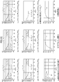
- FIG. 5 shows a simulation result in the simulation 1-1.
- FIG. 5 (a) ⁇ (e) is of the power conditioner PCS i, photovoltaic SP generation amount P i SP (dashed line) of i, rated output P i lmt (solid line), the individual target power P i ref ( (Broken line) and individual output power P i out (solid line) are shown.
- 5A shows the power conditioners PCS 1 and PCS 2
- FIG. 5B shows the power conditioners PCS 3 and PCS 4
- FIG. 5C shows the power conditioners PCS 5 and PCS 6
- 5D shows the power conditioners PCS 7 and PCS 8
- FIG. 5E shows the power conditioners PCS 9 and PCS 10 .
- FIG. 5A to 5E the individual target power P i ref (broken line) is shown slightly shifted upward for convenience of understanding.
- FIG. 5F shows the individual output powers P 1 out to P 10 out of the power conditioners PCS 1 to PCS 10 in one graph.
- FIG. 5G shows the interconnection point power P (t) (solid line) and the output command value P C (broken line) from the power company.
- P C the total value of the rated outputs P 1 lmt to P 10 lmt of PCS 1 to PCS 10 of each power conditioner is output command. Described as the value P C.
- FIG. 5H shows the Lagrangian multiplier ⁇ calculated by the index calculation unit 23.
- FIG. 5I shows the suppression index pr calculated by the index calculation unit 23.
- the individual power conditioners PCS 1 to PCS 10 are individually displayed. Until the output power P 1 out to P 10 out reaches 500 [kW] of the individual target power P 1 ref to P 10 ref , the output power P 1 out to P 10 out increases according to the power generation amount P 1 SP to P 10 SP of the solar cell SP i. Yes. When the individual target powers P 1 ref to P 10 ref reach 500 [kW], the individual output powers P 1 out to P 10 out thereafter become 500 [kW] of the individual target powers P 1 ref to P 10 ref. ] Can be confirmed.
- the Lagrange multiplier ⁇ and the suppression index pr are updated as shown in FIGS. 5 (h) and 5 (i). I can confirm. Then, each of the power conditioners PCS 1 to PCS 10 changes the individual target powers P 1 ref to P 10 ref based on the update of the suppression index pr as shown in FIGS. 5 (a) to 5 (e). Yes. Therefore, it can be confirmed that the individual output powers P 1 out to P 10 out are suppressed and follow the individual target powers P 1 ref to P 10 ref . Thus, as shown in FIG. 5 (g), the suppressed linking point power P (t) is, it can be confirmed that they match the output command value P C in the steady state.
- weights w 5 and w 6 relating to effective power suppression set in two power conditioners PCS 5 and PCS 6 among the ten power conditioners PCS 1 to PCS 10 are the other power conditioners PCS 1.
- the simulation is referred to as simulation 1-2.
- the weight w i for effective power suppression of the two power conditioners PCS 5 and PCS 6 is set to 2.0.
- Other conditions are the same as those in the simulation 1-1.
- FIG. 6 shows a simulation result in the simulation 1-2.
- FIGS. 6A to 6I correspond to FIGS. 5A to 5I in the simulation 1-1, respectively.
- FIGS. 6A to 6E the outputs of the power conditioners PCS 5 and PCS 6 in which the weights w i relating to active power suppression are changed as compared with the simulation 1-1 shown in FIG. It can be confirmed that the suppression amount is half of the output suppression amount of the other power conditioners PCS 1 to PCS 4 and PCS 7 to PCS 10 .
- the Lagrange multiplier ⁇ and the suppression index pr calculated by the central management device MC1 are also the values in the simulation 1-1 (FIG. 5 (h) and FIG. 5). It can also be confirmed that this is different from (i).
- the output suppression amounts of the other power conditioners PCS 1 to PCS 4 and PCS 7 to PCS 10 are reduced by the amount of the output suppression amount of the power conditioners PCS 5 and PCS 6. by greater than -1, as shown in FIG. 6 (g), interconnection point power P (t) is, it can be confirmed that they match the output command value P C in the steady state. Therefore, it can be said that the photovoltaic power generation system PVS1 is appropriately operating in consideration of the weight w i related to the effective power suppression set in the power conditioner PCS i .
- a simulation was performed in which weights w 5 and w 6 relating to effective power suppression of two power conditioners PCS 5 and PCS 6 out of ten power conditioners PCS 1 to PCS 10 were changed halfway. .
- the simulation is referred to as simulation 1-3.
- FIG. 7 shows a simulation result in the simulation 1-3.
- 7A to 7I are diagrams corresponding to FIGS. 5A to 5I in the simulation 1-1, respectively.
- each of the two inverters (PCS 1 and PCS 2 , PCS 3 and PCS 4 , PCS 5 and PCS 6 , PCS 7 and PCS 8 , PCS 9 and PCS 10 ) generates power from the solar cell SP i .
- the case where the amount P i SP is different was simulated. This simulation is referred to as simulation 1-4.
- the solar cells SP i for each of the two inverters (PCS 1 and PCS 2 , PCS 3 and PCS 4 , PCS 5 and PCS 6 , PCS 7 and PCS 8 , PCS 9 and PCS 10 )
- P 8 SP 300 [kW]
- P 9 SP and P 10 SP 200 [kW].
- FIG. 8 shows a simulation result in the simulation 1-4.
- FIGS. 8A to 8I correspond to FIGS. 5A to 5I in the simulation 1-1, respectively.
- FIGS. 8A to 8E when the individual target power P i ref is greater than or equal to the power generation amount P i SP of the solar cell SP i , it can be confirmed that the output is not suppressed.
- FIG. 8F when the power generation amount P i SP of the solar cell SP i is different between the power conditioners PCS 1 to PCS 10 having the same rated output P i lmt , the power generation amount of the solar cell SP i is different. P i SP with less power conditioner PCS 7 ⁇ PCS 10 it can be confirmed that that has not been output suppression. Furthermore, as shown in FIG.
- the solar power generation system PVS1 is appropriately operating in consideration of the power generation amount P i SP of the solar cell SP i .
- FIG. 9 shows a simulation result in the simulation 1-5.
- FIGS. 9A to 9I correspond to FIGS. 5A to 5I in the simulation 1-1, respectively.
- FIG. 9 (f) when the rated output P i lmt is different, it can be confirmed that the output suppression amount is equal for each of the power conditioners PCS 1 to PCS 10 . Further, as shown in FIG. 9G, it can be confirmed that the connection point power P (t) is suppressed and coincides with the output command value P C in a steady state. Therefore, it can be said that the photovoltaic power generation system PVS1 is appropriately operating in consideration of the rated output P i lmt of the power conditioner PCS i .
- simulation 1-6 a case where the sampling time is increased was simulated.
- This simulation is referred to as simulation 1-6.
- the gradient coefficient ⁇ was set to 0.0005
- the output command value P C from the electric power company was set to 3000 [kW] when 0 ⁇ t ⁇ 5 [min] and no command when 5 ⁇ t [min].
- Other conditions are the same as those in the simulation 1-1.
- FIG. 10 shows a simulation result in simulation 1-6.
- 10A to 10I are diagrams corresponding to FIGS. 5A to 5I in the simulation 1-1, respectively.
- FIG. 11 shows a simulation result in simulation 1-7. 11A to 11I correspond to FIGS. 5A to 5I in the simulation 1-1, respectively.
- the Lagrangian multiplier ⁇ and the suppression index pr are the power generation amount P i SP and the rated output P of the solar cell SP i of the power conditioners PCS 1 to PCS 10.
- i lmt, weight w i relating active power suppression, and, on the basis of such an output command value P C it can be confirmed that different values are calculated.
- the individual target power P i ref is updated in accordance with the update of the suppression index pr.
- the power conditioners PCS 1 to PCS 10 control the individual output power P i out according to the individual target power P i ref .
- the suppression index pr calculated by the central management device MC1 using the above equations (9) and (10) is an appropriate value.
- the individual target power P is distributed in a distributed manner based on the suppression index pr received by each power conditioner PCS i from the central management device MC1. i ref is calculated. Therefore, the above target 1-1 is achieved. Further, the interconnection point power P (t) is suppressed, it coincides with the output command value P C. Therefore, the above target 1-2 is achieved.
- the individual output power P i out changes for each power conditioner PCS i according to various conditions. That is, according to various conditions, the output suppression quantity is changed for each power conditioner PCS i. Therefore, the above target 1-3 is achieved. From the above, it can be seen that the photovoltaic power generation system PVS1 has achieved the above three goals.
- the centralized management device MC1 uses the output command value P C from the power company and the detected connection point power P (t) as described above (
- the suppression index pr is calculated using Equation 9) and Equation (10) above, and is transmitted to each power conditioner PCS i .
- each power conditioner PCS i calculates the individual target power P i ref by solving the optimization problem of the above equation (8) in a distributed manner based on the received suppression index pr, and the individual output power the P i out are controlled in a separate target power P i ref.
- the centralized management device MC1 performs only simple calculations shown in the above formulas (9) and (10).
- the processing load of the central management device MC1 can be reduced. Further, even when each power conditioner PCS i calculates the individual target power P i ref in a distributed manner based on the suppression index pr and controls the individual output power P i out , the connection point power P (t ) can be matched to the output command value P C from the power company.
- the solar power generation system PVS1 In the solar power generation system PVS1 according to the first embodiment, the case where the solar power generation system PVS1 is configured by a plurality of power conditioners PCS i to which the solar cells SP i are connected has been described as an example.
- the influence on the output due to weather fluctuation is large. Therefore, in order to suppress output fluctuations due to weather fluctuations or the like, there is a photovoltaic power generation system provided with a power conditioner connected with a solar battery and a power conditioner connected with a storage battery. This case will be described below as a second embodiment.
- FIG. 12 and FIG. 13 are diagrams for explaining the solar power generation system PVS2 according to the second embodiment.
- FIG. 12 is a diagram illustrating an overall configuration of the photovoltaic power generation system PVS2.
- FIG. 13 is a diagram illustrating a functional configuration of a control system that controls electric power at a connection point with the electric power system A in the photovoltaic power generation system PVS2 illustrated in FIG.
- symbol is attached
- the photovoltaic power generation system PVS2 is a grid-connected reverse power flow system.
- Each of the plurality of power conditioners PCS PVi is configured similarly to the power conditioner PCS i of the first embodiment. That is, each power conditioner PCS PVi converts the power (DC power) generated by the solar cell SP i into AC power, and outputs the converted AC power to the power system A.
- Each of the plurality of storage batteries B k is a battery that can repeatedly store power by charging.
- the storage battery B k is a secondary battery such as a lithium ion battery, a nickel metal hydride battery, a nickel cadmium battery, or a lead storage battery.
- a capacitor such as an electric double layer capacitor may be used.
- the storage battery B k discharges the stored power and supplies DC power to the power conditioner PCS Bk .
- Each of the plurality of power conditioners PCS Bk converts DC power input from the storage battery B k into AC power and outputs the AC power. Furthermore, the power conditioner PCS Bk is the AC power input from the electric power system A and each of the power conditioner PCS PVi converted into DC power and supplies the battery B k. That is, the storage battery Bk is charged. Each power conditioner PCS Bk is controlling the charging and discharging of the battery B k. Thus, functions as a discharge circuit to discharge the charging circuit and the battery B k to charge the battery B k.
- each power conditioner PCS PVi When the active power output from each power conditioner PCS PVi is P PVi out and the reactive power is Q PVi out , the complex power of P PVi out + jQ PVi out is output from each power conditioner PCS PVi . Further, assuming that the active power output from each power conditioner PCS Bk is P Bk out and the reactive power is Q Bk out , the complex power of P Bk out + jQ Bk out is output from each power conditioner PCS Bk . Therefore, a plurality of power conditioners PCS PVi, the interconnection point between the PCS Bk and power system A, ( ⁇ i P PVi out + ⁇ k P Bk out) + j ( ⁇ i Q PVi out + ⁇ k Q Bk out) The complex power is output.
- the interconnection point power is the sum of the output powers of the power conditioners PCS PVi and PCS Bk . Also in this embodiment, no particular consideration is given to the output control of reactive powers Q PVi out and Q Bk out that are mainly used for suppressing voltage fluctuation at the interconnection point. That is, the connection point power is the sum of the effective powers P PVi out and P Bk out at the connection point ( ⁇ i P PVi out + ⁇ k P Bk out ).
- the photovoltaic power generation system PVS2 is instructed by the electric power company so that the interconnection point power P (t) does not exceed a predetermined value.
- the solar power generation system PVS2 controls the interconnection point power P (t) according to this instruction.
- photovoltaic systems PVS2 as an instruction from the power company is commanded the output command value P C.
- Photovoltaic systems PVS2 like interconnection point power P (t) is the output command value P C of commanded from the power company, the power conditioner PCS PVi, PCS Bk individual output power P PVi out, P Control Bk out .
- interconnection node power P (t) is the adjusted power, and the target value of the linking point power P (t) the output command value P C.
- Photovoltaic systems PVS2 when interconnection point power P (t) exceeds the output command value P C, suppresses the power conditioner PCS PVi, individual output power P PVi out of PCS Bk, the P Bk out . For this reason, the photovoltaic power generation system PVS2 also performs interconnection point power suppression control.
- each power conditioner PCS PVi receives the suppression index pr PV from the central management device MC2, and calculates the individual target power P PVi ref based on the received suppression index pr PV .
- Suppression indicator pr PV is information for linking point power P (t) to the output command value P C, which is information for calculating the individual target power P PVi ref.
- Each power conditioner PCS PVi controls the individual output power P PVi out based on the calculated individual target power P PVi ref . Therefore, each power conditioner PCS PVi includes a receiving unit 11, a target power calculating unit 12 ′, and an output control unit 13, as shown in FIG.
- the target power calculation unit 12 ′ calculates the individual target power P PVi ref of the own device (power conditioner PCS PVi ) based on the suppression index pr PV received by the reception unit 11. Specifically, the target power calculation unit 12 ′ calculates the individual target power P PVi ref by solving the constrained optimization problem expressed by the following equation (19). Therefore, the target power calculation unit 12 ′ is different from the target power calculation unit 12 according to the first embodiment in the calculation formula of the optimization problem for calculating the individual target power P PVi ref .
- w PVi represents a weight related to active power suppression of the power conditioner PCS PVi , and is a design value.
- P ⁇ i is a design value indicating a design parameter (hereinafter referred to as “priority parameter”) indicating whether or not to give priority to suppression of the individual output power P PVi out of the power conditioner PCS PVi . .
- increasing the priority parameter P .phi.i, to increase the amount of charge of battery B k difficult individual output power P PVi out is suppressed. Therefore, the priority parameter P .phi.i can be said to be a design parameter that indicates whether to prioritize charging of the battery B k.
- this priority parameter P .phi.i the output limit according to the rated output of the power conditioner PCS PVi separately, considered as pseudo output limits of the individual output power P PVi out of the power conditioner PCS PVi is set It is done. Therefore, it can be said that the priority parameter P ⁇ i is a pseudo effective output limit.
- the weight w PVi and the priority parameter P ⁇ i can be set by the user. Details of the following equation (19) will be described later.
- each power conditioner PCS Bk receives the charge / discharge index pr B from the central management device MC2, and calculates the individual target power P Bk ref based on the received charge / discharge index pr B.
- Discharge indicator pr B is information for linking point power P (t) to the output command value P C, which is information for calculating the individual target power P Bk ref. It is also information for determining how much the storage battery B k is charged or discharged.
- Each power conditioner PCS Bk controls the individual output power P Bk out based on the calculated individual target power P Bk ref . Therefore, each power conditioner PCS Bk includes a receiving unit 31, a target power calculating unit 32, and an output control unit 33 as shown in FIG.
- the receiving unit 31 is configured similarly to the receiving unit 11 according to the first embodiment, and receives the charge / discharge indicator pr B transmitted from the central management device MC2.
- the target power calculation unit 32 calculates the individual target power P Bk ref of the own device (power conditioner PCS Bk ) based on the charge / discharge index pr B received by the reception unit 31. Specifically, the target power calculation unit 32 calculates the individual target power P Bk ref by solving the optimization problem expressed by the following equation (20).
- P Bk lmt represents the rated output (output limit) of each power conditioner PCS Bk .
- w Bk represents a weight related to the active power of the power conditioner PCS Bk .
- the weight w Bk can be set by the user.
- ⁇ k and ⁇ k represent adjustment parameters that can be adjusted according to the remaining amount of the storage battery B k . Details of the following equation (20) will be described later.
- the output control unit 33 is configured similarly to the output control unit 13 according to the first embodiment.
- the output control unit 33 controls the discharging and charging of the storage battery B k to set the individual output power P Bk out to the individual target power P Bk ref calculated by the target power calculation unit 32.
- the individual target power P Bk ref calculated by the target power calculation unit 32 is a positive value
- the power (DC power) stored in the storage battery B k is converted into AC power and Supply. That is, the power conditioner PCS Bk is caused to function as a discharge circuit.
- the individual target power P Bk ref is a negative value
- at least part of the AC power output from the power conditioner PCS PVi is converted into DC power and supplied to the storage battery B k . That is, the power conditioner PCS Bk is caused to function as a charging circuit.
- the central management device MC2 centrally manages a plurality of power conditioners PCS PVi and PCS Bk . As shown in FIG. 13, the central management device MC2 is different from the central management device MC1 according to the first embodiment in that the index calculation unit 23 is replaced with an index calculation unit 43 and the transmission unit 24 is replaced with a transmission unit 44. Is different.
- the central control device MC2 at interconnection node power suppression control, calculates a suppression index pr PV and charge-discharge indicator pr B for interconnection point power P (t) to the output command value P C, suppression index pr PV Is transmitted to the power conditioner PCS PVi , and the charge / discharge index pr B is transmitted to the power conditioner PCS Bk .
- Index calculating unit 43 calculates the suppression indicators pr PV and charge-discharge indicator pr B for interconnection point power P (t) to the output command value P C.
- the index calculation unit 43 calculates the suppression index pr PV and the charge / discharge index pr B based on the following formula (21) and the following formula (22), where ⁇ is the Lagrange multiplier, ⁇ is the gradient coefficient, and t is time.
- ⁇ is the Lagrange multiplier
- ⁇ the gradient coefficient
- t time.
- the index calculation unit 43 sets the Lagrange multiplier ⁇ to “ 0 ”. That is, both the suppression index pr PV and the charge / discharge index pr B are calculated as “0”.
- the transmission unit 44 transmits the suppression index pr PV calculated by the index calculation unit 43 to the power conditioner PCS PVi, and transmits the charge / discharge index pr B calculated by the index calculation unit 43 to the power conditioner PCS Bk .
- the photovoltaic power generation system PVS2 is configured to achieve the following five goals in the connection point power suppression control.
- the first target (target 2-1) is “each power conditioner PCS PVi , PCS Bk calculates the individual target power in a distributed manner”.
- the second target (target 2-2) is “not to suppress the output power of the power conditioner PCS PVi connected to the solar cell as much as possible”.
- the third target (target 2-3) is “the storage battery is charged when the interconnection point power is larger than the output command value, and discharged when it is insufficient”.
- the fourth target (target 2-4) is to “match the output power (interconnection point power) at the connection point of the photovoltaic power generation system PVS2 with the output command value from the power company”.
- the fifth target (2-5) is “to allow the output suppression amount to be adjusted for each of the power conditioners PCS PVi and PCS Bk ”.
- equation (23a) represents the minimization of the output suppression amount of the individual output power P PVi out of each power conditioner PCS PVi and the output amount of the individual output power P Bk out of each power conditioner PCS Bk.
- (23b) is a constraint due to the rated output P PVi lmt of each power conditioner PCS PVi
- (23c) is a constraint due to the rated output P Bk lmt of each power conditioner PCS Bk
- the individual target power which is the optimum solution of the above equation (24) is the individual target power P PVi ref obtained by each power conditioner PCS PVi in a distributed manner, but the above equation (23e) is not considered.
- the individual target power that is the optimum solution of the above equation (25) is the individual target power P Bk ref obtained by each power conditioner PCS Bk in a distributed manner, but the above equation (23e) is not taken into consideration. . Therefore, the target 2-4 for matching the interconnection point power P (t) with the output command value P C from the power company cannot be achieved.
- each power conditioner PCS PVi calculates the individual target power P PVi ref in a distributed manner based on the suppression index pr PV received from the central management device MC2, and each power conditioner PCS Bk is calculated by the central management device MC2.
- the individual target power P Bk ref is calculated in a distributed manner based on the charging / discharging index pr B received from.
- the target 2-4 is achieved.
- the constrained optimization problem when each power conditioner PCS PVi obtains the individual target power P PVi ref in a distributed manner using the suppression index pr PV can be expressed by the above equation (19).
- the individual target power P PVi ref which is the optimum solution of the above equation (19) is assumed to be (P PVi ref ) ⁇ .
- the constrained optimization problem when each power conditioner PCS Bk obtains the individual target power P Bk ref in a distributed manner using the charge / discharge index pr B can be expressed by the above equation (20).
- the individual target power P Bk ref that is the optimum solution of the above equation (20) is assumed to be (P Bk ref ) ⁇ .
- the central control device MC2 is calculated Lagrangian multiplier ⁇ as discharge indicator pr B, to present to each power conditioner PCS Bk (transmission), the power conditioner PCS Bk, respectively, above (20)
- the individual target power (P Bk ref ) ⁇ can be calculated from the equation.
- the connection point power P (t) and the output command from the power company The value P C can be matched. That is, the target 2-4 can be achieved.
- each power conditioner PCS PVi optimum solution obtained by PCS Bk (P PVi ref) ⁇ , assuming that (P Bk ref) ⁇ is determined, it becomes the following equation (30), the maximum for the Lagrange multiplier ⁇ It becomes a form of a problem.
- the gradient method is applied to the following equation (30)
- the following equation (31) is obtained. Note that ⁇ represents a gradient coefficient, and ⁇ represents a time variable.
- the central control device MC2 based on the interconnection point power P (t) and the output command value P C from the power company may calculate the Lagrange multiplier lambda. Then, based on the above equation (22), the calculated Lagrangian multiplier ⁇ is used as the suppression index pr PV and the charge / discharge index pr B.
- each power conditioner PCS PVi uses the optimization problem shown in the above equation (19) when calculating the individual target power P PVi ref .
- Each power conditioner PCS Bk uses the optimization problem shown in the above equation (20) when calculating the individual target power P Bk ref .
- the centralized management device MC2 uses the above formula (21) and the above formula (22) when calculating the suppression index pr PV and the charge / discharge index pr B.
- s k denotes the charged electrical energy of the storage battery B k
- K K represents the characteristic of the battery B k.
- the adjustment parameters ⁇ k and ⁇ k that can be adjusted according to the remaining amount of the storage battery B k are set as shown in Table 1.
- Priority parameter of the power conditioner PCS PVi which is a parameter related to the optimization problem (pseudo effective output limit) P .phi.i was 1000 [kW].
- the model of the power system A (interconnection point voltage) (see the above equation (18)) and the models of the power conditioners PCS PVi and PCS Bk (see FIGS. 3 and 4) are related to the first embodiment. The same as in the simulation.
- FIG. 14 to FIG. 16 show the results when simulation is performed under a plurality of conditions using the solar power generation system PVS2 of the model shown above.
- the five power conditioners PCS B1 to PCS B5 all have a rated output P PVi lmt of 500 [kW] and a weight w PVi relating to active power suppression of 1.0.
- the maximum capacities S 1 max to S 5 max of the storage batteries B 1 to B 5 are all 500 [kWh].
- the output command value P C from the electric power company is assumed to be no command when 0 ⁇ t ⁇ 60 [s] and 1500 [kW] when 60 ⁇ t [s]. Note that when “there is no command for the output command value P C ”, as described above, the numerical value ⁇ 1 indicating that there is no command is used as the output command value P C.
- the slope coefficient ⁇ is 0.05
- the update of the suppression index pr PV and the charge / discharge index pr B performed by the central control device MC2
- the individual target powers P PVi ref and P Bk ref performed by the power conditioners PCS PVi and PCS Bk
- Each sampling time with the update of 1 was set to 1 [s].
- FIG. 14 shows a simulation result in the simulation 2-1.
- FIG. 14A shows the power generation amount P i SP of the solar cell SP i .
- FIG. 14B shows the individual target power P PVi ref of each power conditioner PCS PVi .
- FIG. 14C shows the individual output power P PVi out of each power conditioner PCS PVi .
- FIG. 14D shows the interconnection point power P (t) (solid line) and the output command value P C (broken line) from the power company.
- FIG. 14E shows the individual target power P Bk ref of each power conditioner PCS Bk .
- FIG. 14F shows the individual output power P Bk out of each power conditioner PCS Bk .
- FIG. 14G shows the suppression index pr PV and the charge / discharge index pr B calculated by the index calculation unit 43.
- the individual target powers P PV1 ref to P PV5 ref are obtained even after the output command value P C is commanded (60 ⁇ t [s]). It remains 500 [kW], and it can be confirmed that the individual output powers P PV1 out to P PV5 out are not suppressed.
- the individual output powers P B1 out to P B5 out of each power conditioner PCS Bk change from 0 [kW] to negative (minus). It can be confirmed. This represents the fact that the input power to the power conditioner PCS Bk, with the power input to the power conditioner PCS Bk, charging the battery B k. Further, as shown in FIG.
- the interconnection point power P (t) can also be confirmed that it matches the output command value P C.
- solar systems PVS2 when the output command value P C from the power company is commanded not suppress individual output power P PVi out of the power conditioner PCS PVi, it is used to charge the battery B k I can confirm that.
- FIG. 15 shows a simulation result in the simulation 2-2.
- FIGS. 15A to 15G correspond to FIGS. 14A to 14G in the simulation 2-1.
- the weight w B5 relates active power is set to one of the power conditioner PCS B5 is set to the other of the power conditioner PCS B1 ⁇ PCS B4 of five power conditioner PCS B1 ⁇ PCS B5
- This simulation is referred to as simulation 2-3.
- the weight w B5 related to the active power of the one power conditioner PCS B5 is set to 2.0. That is, the charging amount is halved compared with those of the other power conditioners PCS B1 to PCS B4 .
- Other conditions were the same as those in the simulation 2-1.
- FIG. 16 shows a simulation result in the simulation 2-3.
- FIGS. 16A to 16G correspond to FIGS. 14A to 14G in the simulation 2-1.
- the charge amount of the power conditioner PCS B5 having different weight w B5 related to the active power is the other power. It can be confirmed that the conditioners are half of PCS B1 to PCS B4 . Then, as shown in FIG. 16D, it can also be confirmed that the connection point power P (t) matches the output command value P C in a steady state. Therefore, it can be said that the photovoltaic power generation system PVS2 is appropriately operating in consideration of the weight w Bk related to the active power set in the power conditioner PCS Bk .
- the suppression index pr PV and the charge / discharge index pr B are the power generation amounts P of the solar cells SP i of the power conditioners PCS PV1 to PCS PV5 and PCS B1 to PCS B5.
- i SP the performance of the battery B k
- the individual target powers P PVi ref and P Bk ref are updated in accordance with the update of the suppression index pr PV and the charge / discharge index pr B.
- Each of the power conditioners PCS PV1 to PCS PV5 and PCS B1 to PCS B5 controls the individual output powers P PVi out and P Bk out according to the individual target powers P PVi ref and P Bk ref . Therefore, as shown in each figure (d), it can be confirmed that the interconnection point power P (t) coincides with the output command value P C. From the above, it can be said that the suppression index pr PV and the charge / discharge index pr B calculated by the central management device MC2 using the above formulas (21) and (22) are appropriate values.
- each power conditioner PCS PVi calculates the individual target power P Bk ref in a distributed manner based on the charge / discharge index pr B received from the central management device MC2. Therefore, the above target 2-1 is achieved.
- Each power conditioner PCS PVi are individual target power P PVi out not suppress as much as possible, the amount of interconnection point power P (t) exceeds the output command value P C, the power conditioner PCS enter to Bk, it is available to charge the battery B k.
- the above goals 2-2 and 2-3 are achieved.
- the interconnection point power P (t) matches the output command value P C. Therefore, the above target 2-4 is achieved.
- the individual output powers P PVi out and P Bk out change for each power conditioner PCS PVi and PCS Bk according to various conditions. That is, the output suppression amount changes for each power conditioner PCS PVi and PCS Bk according to various conditions. Therefore, the above target 2-5 has been achieved. From the above, it can be seen that the photovoltaic power generation system PVS2 has achieved the above five goals.
- the central control device MC2 is suppressed index pr from the output command value P C and detected interconnection point power P from the power company (t) PV and charge / discharge index pr B are calculated. Then, the suppression index pr PV is transmitted to each power conditioner PCS PVi , and the charge / discharge index pr B is transmitted to each power conditioner PCS Bk .
- Each power conditioner PCS PVi calculates the individual target power P PVi ref by solving the optimization problem of the above equation (19) in a distributed manner based on the received suppression index pr PV . Then, the individual output power P PVi out is controlled to the individual target power P PVi ref .
- each power conditioner PCS Bk calculates the individual target power P Bk ref by solving the optimization problem of the above equation (20) in a distributed manner based on the received charge / discharge index pr B.
- the individual output power P Bk out is controlled to the individual target power P Bk ref .
- the centralized management device MC2 performs only simple calculations shown in the above formula (21) and the above formula (22). Therefore, in the photovoltaic power generation system PVS2, the processing load of the central management device MC2 can be reduced.
- each of the power conditioners PCS PVi and PCS Bk calculates the individual target powers P PVi ref and P Bk ref in a distributed manner based on the suppression index pr PV and the charge / discharge index pr B , respectively, and the individual output powers P PVi out , Even when P Bk out is controlled, the connection point power P (t) can be matched with the output command value P C from the power company.
- the weight w i related to active power suppression is considered, and in the second embodiment, the case where the weight w PVi related to active power suppression and the weight w Bk related to active power are considered is described as an example. However, it is not limited to this. For example, in the first embodiment, if it is not necessary to consider the target 1-3 “allowing the output suppression amount to be adjusted for each power conditioner PCS i ”, it is set for each power conditioner PCS i.
- the weights w i related to the effective power suppression may all be the same value (for example, “1”).
- the power conditioner PCS may all be set to the same value (for example, “1”).
- the target power calculation unit 12 ′ calculates the individual target power P PVi ref using the priority parameter P ⁇ i as in the above equation (19) has been described as an example. as noted above (8) in the first embodiment, it may be used the rated output P PVi lmt. In this case, whether priority is given to the suppression of the individual output power P PVi out or priority is given to the charge / discharge of the storage battery B k (individual output power P Bk out ), the weight w PVi and the weight related to the active power Adjust with w Bk .
- the optimization problem solved by the target power calculation unit 12 ′ is not limited to the above equation (19).
- the following equation (19 ′) may be used instead of the above equation (19).
- the following equation (19 ′) is added to the output current constraint of each power conditioner PCS PVi shown in the following equation (19c ′) as compared with the above equation (19).
- Q PVi the reactive power of the power conditioner PCS PVi
- S PVi d is printable maximum apparent power of the power conditioner PCS PVi
- V 0 is the interconnection at the time of design
- the point reference voltage, V PVi indicates the voltage at the connection point in each power conditioner PCS PVi .
- the optimization problem solved by the target power calculation unit 32 is not limited to the above equation (20).
- the following equation (20 ′) may be used instead of the above equation (20).
- the following equation (20 ′) is added with a weight w SOCk corresponding to the SOC of the storage battery B k in the evaluation function shown in the following (20a ′) as compared with the above equation (20).
- This weight w SOCk is calculated by the following equation (32).
- a SOC's w SOCK offset K SOC is the weight w SOCK gain
- s is the weight w SOCK ON / OFF switch (e.g., 1 When on, the off-0)
- SOC k Indicates the SOC of the current storage battery B k
- SOC d indicates the reference SOC.
- the C rate constraint of the storage battery B k shown in the following equation (20c ′) and the output current constraint of each power conditioner PCS Bk shown in the following equation (20e ′) are added to the constraint conditions.
- the C rate is a relative ratio of the charging time or the time of the discharge current to the total capacitance of the storage battery B k, obtained by the 1C when to charge or discharge the total capacitance of the storage battery B k at 1 hour is there.
- the C rate on the charging side is the charging rate C rate M
- the C rate on the discharging side is the discharging rate C rate P
- predetermined values for example, both 0.3 C
- P SMk lmt is the rated charge output of the storage battery B k obtained by ⁇ C rate M ⁇ WH S lmt (WH S lmt is the rated output capacity of the storage battery B k ), and P SPk lmt is The discharge rated output of the storage battery B k obtained by C rate P ⁇ WH S lmt , Q Bk is the reactive power of each power conditioner PCS Bk , S Bk d is the maximum apparent power that can be output by each power conditioner PCS Bk , V Bk indicates the voltage at the interconnection point in each power conditioner PCS Bk .
- the rated charge output P SMk lmt of the storage battery B k takes into account the storage battery charge amount correction according to the SOC shown in the following equation (33), with the correction start SOC as SOC C and the SOC charge limit threshold as cMAX. .
- the storage battery charge amount correction is performed as usual until the correction start SOC, and from the correction start SOC to the SOC upper limit, the output is corrected linearly so that the output becomes 0 at the SOC upper limit. Yes.
- the rated capacity constraint of each power conditioner PCS Bk shown in the following (20f ′) equation instead of the output current constraint of each power conditioner PCS Bk shown in the following (20e ′), the rated capacity constraint of each power conditioner PCS Bk shown in the following (20f ′) equation. It may be used.
- the target power calculation unit 12 ′ calculates the above-mentioned formula (19) or the above formula (19 ′) when calculating the individual target power P PVi ref. Any of these optimization problems may be used. Similarly, when calculating the individual target power P Bk ref , the target power calculation unit 32 may use any optimization problem of the above equation (20) or the above equation (20 ′).
- the solar power generation system PVS2 in which a plurality of power conditioners PCS PVi and PCS Bk are connected to the interconnection point has been described as an example.
- a power load may be further connected.
- the power load consumes the supplied power, and is, for example, a factory or a general household.
- FIG. 17 and 18 show a photovoltaic power generation system PVS3 according to the third embodiment.
- FIG. 17 shows the overall configuration of the photovoltaic power generation system PVS3.
- FIG. 18 shows a functional configuration of a control system that controls electric power at the interconnection point in the photovoltaic power generation system PVS3 shown in FIG.
- the solar power generation system PVS3 includes a plurality of power conditioners PCS PVi and a plurality of power conditioners PCS Bk . In FIG. 18, only the first one is shown.
- the photovoltaic power generation system PVS3 is different from the photovoltaic power generation system PVS2 according to the second embodiment in that an electric power load L is added.
- the power load L is connected to the interconnection point, and power is supplied from the power system A, each power conditioner PCS PVi , and each power conditioner PCS Bk .
- the sum ⁇ P PVi out of the individual output power P PVi out of each power conditioner PCS PVi exceeds the power consumption of the power load L. .
- a part or all of the surplus power that has not been consumed by the power load L flows backward to the power system A. Excess power is the difference between the individual output power P PVi out of total .SIGMA.P PVi out and the power consumption.
- the solar power generation system PVS3 when to reverse power flow surplus power, it is necessary to prevent this excess power does not exceed the output command value P C from the power company.
- the surplus power that is flowing backward can be regarded as the connection point power P (t) detected by the connection point power detection unit 22. Therefore, the solar power generation system PVS3 performs the connection point power suppression control using the suppression index pr PV and the charge / discharge index pr B , similarly to the second embodiment, so that the connection point power P (t). Is the target power (output command value P C ).
- the central control device MC3 based on the output command value P C and linking point power P from the power company (t), suppression indicators pr PV and charge-discharge index pr B is calculated.
- the central management device MC3 calculates the suppression index pr PV and the charge / discharge index pr B using the above formula (21) and the above formula (22).
- Each power conditioner PCS PVi calculates the individual target power P PVi ref in a distributed manner based on the suppression index pr PV .
- each power conditioner PCS Bk calculates the individual target power P Bk ref in a distributed manner based on the charge / discharge index pr B.
- interconnection point power P (t) i.e., it is possible to control the surplus power to be backward flow to the power grid A to the output command value P C. Therefore, it is possible to prevent the surplus power to flow backward in the power system A from exceeding the output command value P C from the power company.
- FIG. 19 shows a photovoltaic power generation system PVS4 according to the fourth embodiment.
- the solar power generation system PVS4 includes a plurality of power conditioners PCS PVi and PCS Bk .
- FIG. 19 only the first one is shown as in FIG.
- the overall configuration of the photovoltaic power generation system PVS4 is substantially the same as that of the photovoltaic power generation system PVS3 (see FIG. 17) according to the third embodiment.
- the individual output power P PVi out power generation amount P i SP of the solar battery SP i
- each power conditioner PCS PVi exceeds the power consumption of the power load L.
- the sum ⁇ P PVi out of the individual output power P PVi out of each power conditioner PCS PVi (the power generation amount P i SP of the solar cell SP i ) is lower than the power consumption of the power load L. To do. That is, it is assumed that a part or all of the insufficient power that is insufficient for the power generation amount P i SP of the solar cell SP i is supplied from the power system A. Insufficient power is the difference between the individual output power P PVi out of total .SIGMA.P PVi out and the power consumption.
- Electricity charges include basic charges and pay-as-you-go charges.
- the basic charge is determined by the maximum value (peak value), for example, by recording the amount of power used every 30 minutes by a power meter provided at the connection point. Specifically, the basic charge is high when the peak value of power usage is high, and the basic charge is low when the peak value of power usage is low.
- each of the power conditioners PCS PVi and PCS Bk is controlled in a distributed manner using the suppression index pr PV and the charge / discharge index pr B. Suppress the peak value of supplied power (purchased power). This is called “peak cut control”.
- the purchased power is the amount of power supplied from the power system A to the solar power generation system PVS4, that is, the power obtained by the solar power generation system PVS4 from the power system A (purchased).
- the connection point power P (t) has a positive value when it is output from the photovoltaic power generation system PVS4 to the power system A (in the case of reverse power flow).
- connection point electric power P (t) becomes a negative value.
- the target value is set to a negative value, and control is performed so that the interconnection power P (t) does not fall below the target value.
- Photovoltaic systems PVS4 in the peak-cut control, to control the individual output power P PVi out of the power conditioner PCS PVi, and outputs all the electric power generated by the solar cell SP i. Further, the individual output power P Bk out of each power conditioner PCS Bk is controlled, and the power stored in the storage battery B k is discharged as necessary. In this way, a part of the power consumption of the power load L is supplemented with the power generated by the solar battery SP i and the power stored in the storage battery B k , thereby suppressing the increase in the purchased power. .
- the central management device MC4 differs from the central management device MC2 according to the second embodiment in the following points. That is, the central management device MC4 includes a peak cut setting unit 45 instead of the output command value acquisition unit 21, and includes an index calculation unit 43 ′ instead of the index calculation unit 43.
- the peak cut setting unit 45 performs various settings for peak cut control.
- the peak cut setting unit 45 sets the peak cut target power P cut with the upper limit value being a negative value based on the upper limit value of the purchased power.
- This peak cut target power P cut is a target value of the interconnection point power P (t) and is a negative value.
- the peak cut target power P cut is arbitrarily set by the user.
- the peak cut setting unit 45 outputs the set peak cut target power P cut to the index calculation unit 43 ′.
- Index calculating unit 43 uses the second compared to the index calculation unit 43 according to the embodiment, the peak-cut target power P cut inputted from the peak cut setting unit 45 instead of the output command value P C,
- the suppression index pr PV and the charge / discharge index pr B are calculated. That is, in the present embodiment, the index calculation unit 43 ′ calculates the suppression index pr PV and the charge / discharge index pr B for making the interconnection point power P (t) the peak cut target power P cut . At this time, the index calculation unit 43 ′ calculates the Lagrange multiplier ⁇ using the peak cut target power P cut instead of the output command value P C (t) in the equation (21). Then, the calculated Lagrangian multiplier ⁇ is calculated as the charge / discharge index pr B by the above equation (22).
- the index calculation unit 43 ′ calculates only the charge / discharge index pr B.
- the index calculation unit 43 ′ transmits the calculated suppression index pr PV to each power conditioner PCS PVi via the transmission unit 44. Further, the calculated charging / discharging index pr B is transmitted to each power conditioner PCS Bk via the transmission unit 44.
- Each power conditioner PCS PVi calculates the individual target power P PVi ref based on the optimization problem using the suppression index pr PV calculated by the central management device MC4, and the individual output power P PVi out is the individual target power. It is controlled to become P PVi ref .
- each power conditioner PCS Bk calculates the individual target power P Bk ref based on the optimization problem using the charge / discharge index pr B calculated by the centralized management device MC4, and calculates the individual output power P Bk out . Control to individual target power P Bk ref . Accordingly, when the interconnection point power P (t) is equal to or less than the peak cut target power P cut , all the power generated by the solar cell SP i is output, and the power stored in the storage battery B k is discharged. Is done. As a result, the connection point power P (t) increases, and the connection point power P (t) becomes the peak cut target power P cut . Therefore, the connection point power P (t) is suppressed from being equal to or lower than the peak cut target power P cut , and the solar power generation system PVS4 suppresses the peak value.
- the centralized management device MC4 controls this to the peak cut target power P cut . Therefore, depending on the detection interval of the interconnection point power P (t) and the calculation intervals of the suppression index pr PV and the charge / discharge index pr B , the peak cut target power P cut is instantaneously reduced. Therefore, when setting the upper limit value of purchased power, a value smaller than the upper limit value desired by the user may be set. Thereby, since the peak cut target power P cut is set to a value larger than the actual target value, even if the interconnection point power P (t) instantaneously decreases, the peak cut target power P cut is not more than the peak cut target power P cut. Can be suppressed.
- the connection point power P (t) can be set to the target power (peak cut target power P cut ). Furthermore, each power conditioner PCS PVi and PCS Bk obtains the individual target powers P PVi ref and P Bk ref in a distributed manner, thereby reducing the processing load on the central management device MC4.
- the power stored in battery B k decreases. Therefore, when filled with predetermined charging conditions, using a portion of the power supplied from the power system A, it may be to charge the battery B k. Examples of such charging conditions include a case where the interconnection point power P (t) is larger than the peak cut target power P cut by a threshold value or more. By doing in this way, storage battery Bk can be charged in preparation for the next peak cut control.
- the charging mode can be set for each predetermined time zone. Then, in accordance with the charging mode, it controls the charging of the battery B k.
- Examples of such a charging mode include a no-charge mode, a normal charging mode, and a low-speed charging mode.
- the no-charge mode is a mode in which charging is not performed.
- the normal charging mode is a mode for charging at a predetermined charging speed (normal speed).
- the low-speed charging mode is a mode for charging at a predetermined speed (low speed) slower than the normal speed.
- the charging mode is not limited to these.
- the user can set the charging mode through the user interface of the centralized management device MC4, and the peak cut setting unit 45 sets the charging mode according to the user's operation instruction.
- the predetermined time period is a predetermined period in which one day is divided into a plurality of times. For example, when divided every hour, it can be set every 24 time periods and divided every 30 minutes. In this case, it can be set every 48 time zones. It may be divided into time zones such as morning, noon, evening, evening, and midnight. Further, a predetermined time zone may be provided not in units of days but in units of weeks.
- the central management device MC4 transmits the charging mode setting information set by the peak cut setting unit 45 to each of the power conditioners PCS Bk via the transmission unit 44.
- Each power conditioner PCS Bk received this via the receiving unit 31, the storage battery B shown above (20c ') equation using the charging rate C rate M associated with the charging mode is set Change the C rate constraint (charge rated output P SMk lmt ) of k .
- the charging rate C rate M for the normal charging mode is set to 0.3
- the charging rate C rate M for the low speed charging mode is set to 0.1
- the charging rate C rate M for the no charging mode is set to 0. .
- Each power conditioner PCS Bk obtains the individual target power P Bk ref based on the optimization problem shown in the above equation (20 ′), so that the storage battery B k is charged according to the setting of the charging mode. And the charging speed can be changed.
- the charging speed may be variable so that the storage battery Bk is fully charged in the time zone in which the low-speed charging mode is continuously set. For example, when the “low-speed charging mode” is set continuously from midnight to 6:00 am, the charging speed is set so that the storage battery Bk is fully charged over 6 hours.
- the charging rate C rate M is set to 1/6 ( ⁇ 0.167). However, it is desirable not to exceed the normal speed.
- the charging mode it is possible to change whether or charging rate of the charging of the appropriate battery B k. Therefore, when the unit price of the pay-as-you-go charge (for purchasing electricity) varies depending on the time of day, for example, the amount of purchased power is increased during a period when the unit price of electricity is low, and the power is purchased during a period when the unit price of power is high. Electric power can be reduced.
- the case where a plurality of power conditioners PCS PVi to which the solar cells SP i are connected is described as an example, but these may not be provided. That may be those composed of battery B k are connected to a plurality of power conditioners PCS Bk and power load L and the central control device MC4.
- FIG. 20 shows a photovoltaic power generation system PVS5 according to the fifth embodiment.
- the solar power generation system PVS5 includes a plurality of power conditioners PCS PVi and PCS Bk .
- FIG. 20 only the first one is shown as in FIG.
- the overall configuration of the solar power generation system PVS5 is substantially the same as that of the solar power generation system PVS3 (see FIG. 17) according to the third embodiment.
- RPR 51 reverse power relay
- the RPR 51 is a kind of relay.
- the RPR 51 detects that a reverse power flow has occurred in the power system A from the solar power generation system PVS5
- the RPR 51 shuts off the solar power generation system PVS5 from the power system A. Once shut off, it takes time because it is necessary to call a specialist to return. For example, the power consumption of the power load L decreases when the power load L is low due to, for example, a factory stoppage day.
- the power conditioners PCS PVi and PCS Bk are controlled in a distributed manner using the suppression index pr PV and the charge / discharge index pr B to generate reverse power flow. Suppress. This is called “reverse power flow avoidance control”.
- the connection point power P (t) is a positive value
- a reverse power flow is generated. Therefore, in order to suppress the generation of the reverse power flow, the connection point power P (t) is a positive value. It is sufficient to maintain a negative value so as not to become.
- the solar power generation system PVS5 suppresses the individual output power P PVi out of each power conditioner PCS PVi in the reverse power flow avoidance control. Further, to charge the battery B k controls the individual output power P Bk out of the power conditioner PCS Bk. In this way, power is always supplied from the power system A to the solar power generation system PVS5. Accordingly, the negative value is maintained so that the interconnection point power P (t) does not become a positive value. Thereby, generation
- the central management device MC5 differs from the central management device MC2 according to the second embodiment in the following points. That is, the centralized management device MC5 includes a reverse power flow avoidance setting unit 46 instead of the output command value acquisition unit 21, and includes an index calculation unit 43 ′′ instead of the index calculation unit 43.
- the reverse power flow avoidance setting unit 46 performs various settings for reverse power flow avoidance control.
- the reverse power flow avoidance setting unit 46 sets a reverse power flow avoidance target power PRPR for suppressing the occurrence of reverse power flow.
- This reverse power flow avoidance target power PRPR is a target value of the interconnection point power P (t) and is a negative value.
- the reverse power flow avoidance target power PRPR is arbitrarily set by the user.
- the reverse power flow avoidance setting unit 46 outputs the set reverse power flow avoidance target power PRPR to the index calculation unit 43 ′′.
- Index calculating unit 43 ' calculates the suppression indicators pr PV and charge-discharge indicator pr B for interconnection point power P (t) to reverse flow around the target power P RPR. That is, in this embodiment, the index calculator 43 ', as compared with the index calculation unit 43 according to the second embodiment, by using the backward flow around the target power P RPR inputted from the reverse flow prevention settings unit 46 instead of the output command value P C Then, the suppression index pr PV and the charge / discharge index pr B are calculated. Specifically, the index calculation unit 43 ′′ calculates the Lagrange multiplier ⁇ using the reverse power flow avoidance target power PRPR instead of the output command value P C (t) in the equation (21).
- the calculated Lagrangian multiplier ⁇ is calculated as the suppression index pr PV and the charge / discharge index pr B by the equation (22).
- the index calculation unit 43 ′′ transmits the calculated suppression index pr PV to the power condition via the transmission unit 44. Send to NAPCS PVi . Further, the calculated charge / discharge index pr B is transmitted to the power conditioner PCS Bk via the transmission unit 44.
- the central management device MC5 monitors the connection point power P (t) detected by the connection point power detection unit 22.
- the index calculation unit 43 ′′ changes the connection point power P (t) to the reverse power flow avoidance target power PRPR. to the calculated suppression indicators pr PV and charge-discharge indicator pr B.
- each power conditioner PCS PVi based on the optimization problem using suppression index pr PV to the central control device MC5 has been calculated, the individual target power P PVi ref is calculated, and the individual output power P PVi out is controlled to the individual target power P PVi ref , and each power conditioner PCS Bk is optimized using the charge / discharge index pr B calculated by the central control device MC5.
- the individual target power P Bk ref is calculated, and the individual output power P Bk out is controlled to the individual target power P Bk ref , whereby the connection point power P (t) is converted to the reverse power flow avoidance target power P. to control the RPR, head tide It has a generation suppression. That, RPR51 by reverse flow is prevented from operating.
- the set value of the reverse power avoidance target power PRPR is 0 (or close to 0), it depends on the detection interval of the connection point power P (t) and the calculation interval of the suppression index pr PV and the charge / discharge index pr B.
- the connection point power P (t) increases instantaneously, the connection point power P (t) becomes a positive value and a reverse power flow may occur.
- the reverse power flow avoidance target power PRPR to be set is preferably set to a value smaller than 0 by a predetermined amount or less.
- the inverse of the reverse flow prevention settings unit 46 sets, instead of the output command value P C Even when the tidal current avoidance target power PRPR is used, the interconnection point power P (t) can be set to the target power (reverse power flow avoidance target power PRPR ). Furthermore, each power conditioner PCS PVi and PCS Bk obtains the individual target powers P PVi ref and P Bk ref in a distributed manner, thereby reducing the processing load on the central management device MC4.
- the power is accumulated in the battery B k. Therefore, when filled with a predetermined discharge condition may be to discharge the battery B k. Examples of such discharge conditions include a case where the interconnection point power P (t) is smaller than the reverse power flow avoidance target power PRPR by a threshold value or more. By doing in this way, the storage battery Bk can be discharged in preparation for the next reverse power flow avoidance control.
- discharge control of the storage battery B k whether or not to discharge may be changed for each predetermined time period.
- the discharge mode can be set for each predetermined time period. And according to the said discharge mode, it is controlled whether the storage battery Bk is discharged.
- discharge modes include, for example, a discharge mode and a discharge no mode.
- the discharge mode is a mode in which discharge is performed.
- the no discharge mode is a mode in which no discharge is performed.
- the discharge mode is not limited to these.
- the user can set the discharge mode by using the user interface of the central management device MC5, and the reverse power flow avoidance setting unit 46 sets the discharge mode according to the user's operation instruction.
- the predetermined time zone at this time may be the same as or different from the predetermined time zone in the peak cut control.
- the central management device MC5 transmits the discharge mode setting information set by the reverse power flow avoidance setting unit 46 to each power conditioner PCS Bk via the transmission unit 44.
- Each power conditioner PCS Bk received this via the receiving unit 31, the storage battery B shown above (20c ') equation using the discharge rate C rate P associated with the discharge mode that is set Change the C rate constraint (discharge rated output P SPk lmt ) of k .
- 0.3 is the discharge rate C rate P to the discharge chromatic mode
- the discharge rate C rate P to the discharge-free mode is set to 0, respectively.
- the power conditioner PCS Bk obtains the individual target power P Bk ref based on the optimization problem shown in the above equation (20 ′), and thereby discharges the storage battery B k according to the setting of the discharge mode. Can be changed. By doing in this way, it can change suitably whether storage battery Bk is discharged according to discharge mode. Therefore, the electric power can be accumulated without discharging the storage battery B k as necessary.
- the case where a plurality of power conditioners PCS Bk to which the storage battery B k is connected is described as an example. However, these may not be provided. That is, it may be configured by a plurality of power conditioners PCS PVi , a power load L, and a central management device MC5 to which the solar cell SP i is connected.
- the photovoltaic power generation system PVS5 performs the reverse power flow avoidance control, the reverse power flow in which the connection point power P (t) is set only by suppressing the individual output power P PVi out from the power conditioner PCS PVi.
- the avoidance target power PRPR is set.
- the solar power generation systems PVS3, PVS4, and PVS5 in which the interconnection point power suppression control, peak cut control, and reverse power flow avoidance control are individually implemented have been described. It is also possible to combine various controls. In this case, it is only necessary to switch which control the centralized management apparatus performs as appropriate. For example, switching may be performed according to the user's operation, the situation (positive / negative of the connection point power P (t) (whether or not reverse flow is in progress), reverse flow is prohibited, or power of the power load L It may be automatically switched according to a consumption history or a working day.
- connection point power P (t) detected by the connection point power detection unit 22 is set to the target power (output command value P C , peak cut target power P cut , or It has described the case of controlling the backward flow avoidance target power P RPR), but is not limited thereto.
- the centralized management device instead of the connection point power P (t) detected by the connection point power detection unit 22, uses the individual output power P i out , from each of the power conditioners PCS i , PCS PVi , PCS Bk .
- system total output the total sum of the obtained individual output powers P i out , P PVi out and P Bk out. Also good.
- FIG. 21 and 22 show a photovoltaic power generation system PVS6 according to the sixth embodiment.
- FIG. 21 shows the overall configuration of the photovoltaic power generation system PVS6.
- FIG. 22 shows a functional configuration of a control system that controls the total system output in the photovoltaic power generation system PVS6 shown in FIG.
- the solar power generation system PVS6 includes a plurality of power conditioners PCS PVi and PCS Bk . In FIG. 22, only the first one is shown as in FIG.
- the photovoltaic power generation system PVS6 does not detect the connection point power P (t), and sums all of the individual output powers P PVi out and P Bk out of the power conditioners PCS PVi and PCS Bk. (System total output P total (t)) is calculated, and the system total output P total (t) is controlled to be the output command value P C instructed by the electric power company. That is, in this embodiment, the system total output P total (t) is the adjusted power, and, and the output command value P C and a target power of the total system output P total (t).
- the control performed by the photovoltaic power generation system PVS6 is referred to as “system total output suppression control”.
- the photovoltaic power generation system PVS6 differs from the photovoltaic power generation system PVS2 according to the second embodiment in the following points. That is, the central management device MC6 does not include the interconnection point power detection unit 22, but has a configuration for obtaining the individual output powers P PVi out and P Bk out from the power conditioners PCS PVi and PCS Bk , respectively. Yes. Specifically, each power conditioner PCS PVi further includes an output power detection unit 14 and a transmission unit 15, and each power conditioner PCS Bk further includes an output power detection unit 34 and a transmission unit 35, respectively. ing. Further, the central management device MC6 includes a receiving unit 61, a total output calculating unit 62, and an index calculating unit 63 instead of the interconnection point power detecting unit 22 and the index calculating unit 43.
- the output power detection unit 14 is provided in each power conditioner PCS PVi and detects the individual output power P PVi out of its own device.
- the output power detection unit 34 is provided in each power conditioner PCS Bk and detects the individual output power P Bk out of its own device.
- the transmission unit 15 transmits the individual output power P PVi out detected by the output power detection unit 14 to the central management device MC6.
- the transmission unit 35 transmits the individual output power P Bk out detected by the output power detection unit 34 to the central management device MC6.
- the receiving unit 61 receives the individual output powers P PVi out and P Bk out transmitted from the power conditioners PCS PVi and PCS Bk .
- the total output calculation unit 62 calculates a system total output P total (t) that is the sum of the individual output powers P PVi out and P Bk out received by the reception unit 61. In the present embodiment, the total output calculation unit 62 calculates the total system output P total (t) obtained by adding all the individual output powers P PVi out and P Bk out that are input.
- the total output calculation section 62 calculates the systems total output P total (t), calculates the suppression indicators pr PV and charge-discharge indicator pr B to the output command value P C.
- the index calculation unit 63 calculates the Lagrange multiplier ⁇ using the system total output P total (t) instead of the interconnection point power P (t) in the above equation (21).
- the calculated Lagrangian multiplier ⁇ is calculated as the suppression index pr PV and the charge / discharge index pr B by the above equation (22).
- the calculated suppression index pr PV is transmitted to each power conditioner PCS PVi via the transmission unit 44.
- the calculated charge / discharge index pr B is transmitted to each power conditioner PCS Bk via the transmission unit 44.
- the system total output Ptotal (t) is used as the adjustment target power instead of the interconnection power P (t) in the second embodiment.
- the system total output P total (t) can be set to the target power (output command value P C ).
- the power conditioners PCS PVi and PCS Bk obtain the individual target powers P PVi ref and P Bk ref in a distributed manner, the processing load on the central management device MC6 can be reduced.
- the solar power generation system PVS6 in which each of the power conditioners PCS PVi and PCS Bk is connected to the interconnection point has been described as an example.
- the power load L may be provided.
- FIG. 23 and 24 show a solar power generation system PVS7 according to the seventh embodiment.
- FIG. 23 shows the overall configuration of the photovoltaic power generation system PVS7.
- FIG. 24 shows a functional configuration of a control system that controls the total system output in the photovoltaic power generation system PVS7 shown in FIG.
- the solar power generation system PVS7 includes a plurality of power conditioners PCS PVi and PCS Bk . In FIG. 24, only the first one is shown as in FIG.
- the photovoltaic power generation system PVS7 is further compared to the photovoltaic power generation system PVS6 according to the sixth embodiment in that an electric power load L is connected to the interconnection point.
- the total system output suppression control using the suppression index pr PV and the charge / discharge index pr B is performed based on the calculated total system output P total (t), as in the sixth embodiment. be able to. Therefore, as in the sixth embodiment, while the system total output P total (t) to the output command value P C, it is possible to reduce the processing load of the central control device MC7.
- FIG. 25 shows a photovoltaic power generation system PVS8 according to the eighth embodiment.
- the solar power generation system PVS8 includes a plurality of power conditioners PCS PVi and PCS Bk .
- the overall configuration of the solar power generation system PVS8 is substantially the same as that of the solar power generation system PVS7 according to the seventh embodiment.
- the photovoltaic power generation system PVS8 according to the eighth embodiment includes a plurality of power conditioners PCS PVi and PCS Bk , a first power conditioner group G PV that is a set of a plurality of power conditioners PCS PVi , and a plurality of power conditioners PCS PVi . a case in which divided into two groups of the second power conditioner group G B is the set of the power conditioner PCS Bk will be described as an example.
- the solar power generation system PVS8 sets a target power for each of the first power conditioner group G PV and the second power conditioner group G B, and sets the first power conditioner group G PV.
- the total output power and the total output power of the second power conditioner group G B in is controlled to respectively become the target power. This control is called “schedule control”.
- the total output power of the first power conditioner group G PV is the sum ⁇ P PVi out of the individual output powers P PVi out of each power conditioner PCS PVi , and is hereinafter referred to as the first group total output P GPV .
- the total output power of the second power conditioner group G B is the sum .SIGMA.P Bk out of individual output power P Bk out of the power conditioner PCS Bk, hereinafter referred to as the second group the total output P GB.
- the solar power generation system PVS8 differs from the solar power generation system PVS7 according to the seventh embodiment in the following points as shown in FIG. 25 in order to perform schedule control. That is, in the central management device MC8, the schedule setting unit 64 is replaced instead of the output command value acquiring unit 21, the total output calculating unit 62 ′ is replaced instead of the total output calculating unit 62, and the index calculation is performed instead of the index calculating unit 63. A portion 63 ′ is provided.
- the schedule setting unit 64 performs various settings for schedule control.
- the schedule setting unit 64 includes the first group target power P TPV that is the target value of the first group total output P GPV and the second group target power P that is the target value of the second group total output P GB.
- Set TB The first group target power P TPV and the second group target power P TB can be set for each predetermined time period. These set values are arbitrarily set by the user.
- the schedule setting unit 64 outputs the various set values that have been set to the index calculation unit 63 ′.
- the total output calculation unit 62 ′ calculates the first group total output P GPV and the second group total output P GB , respectively. Specifically, the total output calculation unit 62 ′ calculates the first group total output P GPV by adding the individual output power P PVi out of the power conditioner PCS PVi received by the reception unit 61. The total output calculation unit 62 'adds the individual output power P Bk out of the power conditioner PCS Bk the receiving unit 61 has received, it calculates the total output P GB second group.
- the index calculation unit 63 ′ calculates a suppression index pr PV for making the first group total output P GPV calculated by the total output calculation unit 62 ′ into the first group target power P TPV input from the schedule setting unit 64. To do. At this time, the index calculation unit 63 ′ calculates the suppression index pr PV using the following equation (34).
- ⁇ PV represents a Lagrange multiplier for a plurality of power conditioners PCS PVi
- ⁇ PV represents a gradient coefficient for the plurality of power conditioners PCS PVi .
- the index calculation unit 63 ′ uses the first group total output P GPV (t) instead of the interconnection point power P (t) in the above equation (9), instead of the output command value P C (t).
- a Lagrange multiplier ⁇ PV is calculated using the first group target power P TPV (t).
- the calculated Lagrangian multiplier ⁇ PV is set as the suppression index pr PV .
- the index calculation unit 63 ′ transmits the calculated suppression index pr PV to each power conditioner PCS PVi via the transmission unit 44.
- the index calculation unit 63 ′ sets a charge / discharge index pr B for making the second group total output P GB calculated by the total output calculation unit 62 ′ into the second group target power P TB input from the schedule setting unit 64. calculate. At this time, the index calculation unit 63 ′ calculates the charge / discharge index pr B using the following equation (35).
- ⁇ B represents a Lagrange multiplier for a plurality of power conditioners PCS Bk
- ⁇ B represents a gradient coefficient for the plurality of power conditioners PCS Bk .
- the index calculation unit 63 ′ uses the second group total output P GB (t) instead of the interconnection power P (t) in the above equation (9), instead of the output command value P C (t).
- a Lagrange multiplier ⁇ B is calculated using the second group target power P TB (t).
- the calculated Lagrangian multiplier ⁇ B is used as the charge / discharge index pr B.
- the index calculation unit 63 ′ transmits the calculated charge / discharge index pr B to each power conditioner PCS Bk via the transmission unit 44.
- the central management device MC8 obtains the individual output power P PVi out from each power conditioner PCS PVi, and calculates the first group total output P GPV . Then, the suppression index pr PV is calculated using the above equation (34) so that the calculated first group total output P GPV becomes the first group target power P TPV . The calculated suppression index pr PV is transmitted to each power conditioner PCS PVi . Each power conditioner PCS PVi calculates the individual target power P PVi ref using the received suppression index pr PV and controls the individual output power P PVi out to become the individual target power P PVi ref .
- the central management device MC8 obtains the individual output power P Bk out from the power conditioner PCS Bk, and calculates the second group total output P GB . Then, the charge / discharge index pr B is calculated using the above equation (35) so that the calculated second group total output P GB becomes the second group target power P TB . The calculated charge / discharge index pr B is transmitted to each power conditioner PCS Bk . Each power conditioner PCS Bk calculates the individual target power P Bk ref using the received charge / discharge index pr B and controls the individual output power P Bk out to be the individual target power P Bk ref . As a result, the first group total output P GPV becomes the first group target power P TPV , and the second group total output P GB becomes the second group target power P TB .
- the solar power generation system PVS8 According to the solar power generation system PVS8 according to this embodiment, and target power (first group target power P TPV to the first power conditioner group G PV and the second power for each conditioner group G B No. Set the second group target power P TB ), the first group total output P GPV becomes the first group target power P TPV , and the second group total output P GB becomes the second group target power P TB.
- the power conditioners PCS PVi and PCS Bk calculate the individual target powers P PVi ref and P Bk ref in a distributed manner based on the suppression index pr PV and the charge / discharge index pr B , respectively. Processing load can be reduced.
- a plurality of power conditioners PCS PVi and PCS Bk are used as a first power conditioner group G PV that is a set of a plurality of power conditioners PCS PVi and a plurality of power conditioners PCS Bk. It is a set of but a case in which divided into two groups with the second power conditioner group G B is described as an example, but is not limited thereto.
- the first power conditioner group G PV further divided into a plurality of groups, may be set the target power for each the group.
- the second power conditioner group G B may be grouped so that both one or more power conditioners PCS PVi and one or more power conditioners PCS Bk are included, and target power may be set for each group.
- the suppression index pr PV and the charge / discharge index pr B may be calculated for each group using the formula (21) and the formula (22).
- the solar power generation systems PVS7 and PVS8 in which the system total output suppression control and the schedule control are individually implemented have been described, but it is also possible to combine them.
- the central management devices MC7 and MC8 have a configuration in which the individual output powers P PVi out and P Bk out are obtained from the power conditioners PCS PVi and PCS Bk.
- a configuration for obtaining the power consumption of the power load L from the power load L may be added.
- the connection point power P (t) can be estimated. Therefore, the interconnection point power suppression control, the peak cut control, and the reverse power flow avoidance control described in the third to fifth embodiments can be performed even if the interconnection point power detection unit 22 is not provided. it can.
- connection point power suppression control In the third embodiment to the fifth embodiment, the case where the connection point power suppression control, the peak cut control, and the reverse power flow avoidance control are performed based on the connection point power P (t) is described as an example.
- the seventh embodiment and the eighth embodiment based on the total system output P total (t), the first group total output P GPV and the second group total output P GB , the system total output suppression control and the schedule control, respectively.
- the present invention is not limited to this. Both means for detecting the connection point power P (t) (connection point power detection unit 22) and means for obtaining the individual output powers P PVi out and P Bk out from the power conditioners PCS PVi and PCS Bk , respectively, are provided.
- the interconnection point power suppression control, peak cut control, reverse power flow avoidance control, system total output suppression control, and schedule control may be controlled in combination.
- the case where the power system according to the present disclosure is applied to a solar power generation system has been described as an example.
- the power system may be applied to another power generation system such as a wind power generation system. Good.
- PVS1 ⁇ PVS8 photovoltaic system A power system SP i solar cell B k accumulator PCS i, PCS PVi, PCS Bk power conditioner G PV first power conditioner group G B second power conditioner groups 11 and 31 received 12 , 12 ′, 32 Target power calculation unit 13, 33 Output control unit 14 Output power detection unit 15 Transmission unit MC1 to MC8 Centralized management device 21 Output command value acquisition unit 22 Interconnection point power detection unit 23, 43, 43 ′, 43 ”Index calculation unit 24, 44 Transmission unit 45 Peak cut setting unit 46 Reverse power flow avoidance setting unit 51 RPR (reverse power relay) 61 Receiving Unit 62, 62 ′ Total Output Calculation Unit 63, 63 ′ Index Calculation Unit 64 Schedule Setting Unit L Power Load
Abstract
Priority Applications (4)
| Application Number | Priority Date | Filing Date | Title |
|---|---|---|---|
| US16/081,276 US10871795B2 (en) | 2016-03-02 | 2017-02-24 | Electric power system |
| DE112017001108.6T DE112017001108T5 (de) | 2016-03-02 | 2017-02-24 | Stromversorgungssystem |
| AU2017226244A AU2017226244B2 (en) | 2016-03-02 | 2017-02-24 | Electric power system |
| JP2018503104A JP6790330B2 (ja) | 2016-03-02 | 2017-02-24 | 電力システム |
Applications Claiming Priority (2)
| Application Number | Priority Date | Filing Date | Title |
|---|---|---|---|
| JP2016040308 | 2016-03-02 | ||
| JP2016-040308 | 2016-03-02 |
Publications (1)
| Publication Number | Publication Date |
|---|---|
| WO2017150376A1 true WO2017150376A1 (fr) | 2017-09-08 |
Family
ID=59744153
Family Applications (1)
| Application Number | Title | Priority Date | Filing Date |
|---|---|---|---|
| PCT/JP2017/007105 WO2017150376A1 (fr) | 2016-03-02 | 2017-02-24 | Système d'alimentation électrique |
Country Status (5)
| Country | Link |
|---|---|
| US (1) | US10871795B2 (fr) |
| JP (1) | JP6790330B2 (fr) |
| AU (1) | AU2017226244B2 (fr) |
| DE (1) | DE112017001108T5 (fr) |
| WO (1) | WO2017150376A1 (fr) |
Cited By (7)
| Publication number | Priority date | Publication date | Assignee | Title |
|---|---|---|---|---|
| JP2019122150A (ja) * | 2018-01-05 | 2019-07-22 | 株式会社ダイヘン | 電力システムおよび蓄電池パワーコンディショナ |
| WO2019193837A1 (fr) * | 2018-04-05 | 2019-10-10 | 株式会社日立製作所 | Système de génération de puissance et son procédé de commande |
| JP2020018108A (ja) * | 2018-07-25 | 2020-01-30 | パナソニックIpマネジメント株式会社 | 蓄電システム |
| JP2020043642A (ja) * | 2018-09-07 | 2020-03-19 | 株式会社ダイヘン | 電力システムおよび処理装置 |
| CN111653080A (zh) * | 2020-06-03 | 2020-09-11 | 贵州电网有限责任公司 | 一种基于数据线连接的数据传输方法、装置及通信终端 |
| JP2021069170A (ja) * | 2019-10-21 | 2021-04-30 | 東芝三菱電機産業システム株式会社 | 太陽光発電システム |
| WO2023079327A1 (fr) | 2021-11-08 | 2023-05-11 | 日産自動車株式会社 | Procédé de commande de charge/décharge et dispositif de commande de charge/décharge |
Families Citing this family (5)
| Publication number | Priority date | Publication date | Assignee | Title |
|---|---|---|---|---|
| US11616367B2 (en) * | 2017-07-17 | 2023-03-28 | Johnson Controls Technology Company | Energy storage system with virtual device manager |
| AU2018200745A1 (en) * | 2018-01-31 | 2019-08-15 | Rheem Australia Pty Limited | Improved water heater control arrangement and assembly |
| US20210124854A1 (en) * | 2019-10-28 | 2021-04-29 | General Electric Company | Systems and methods for enhanced power system model parameter estimation |
| EP4057464A1 (fr) * | 2021-03-12 | 2022-09-14 | Výzkumné a vývojové centrum obnovitelných zdroju a elektromobility s.r.o. | Connexion d'un réseau de sources de tension continue extra-basse |
| CN113659584A (zh) * | 2021-07-26 | 2021-11-16 | 珠海格力节能环保制冷技术研究中心有限公司 | 设备的用电控制方法及设备 |
Citations (2)
| Publication number | Priority date | Publication date | Assignee | Title |
|---|---|---|---|---|
| JP2013005537A (ja) * | 2011-06-14 | 2013-01-07 | Sharp Corp | 発電システム及び発電装置 |
| JP2013207862A (ja) * | 2012-03-27 | 2013-10-07 | Sharp Corp | 発電システム、並びに当該発電システムに用いるパワーコンディショナおよび出力抑制管理装置 |
Family Cites Families (10)
| Publication number | Priority date | Publication date | Assignee | Title |
|---|---|---|---|---|
| US7598623B2 (en) * | 2006-12-29 | 2009-10-06 | Cummins Power Generation Ip, Inc. | Distinguishing between different transient conditions for an electric power generation system |
| US7983799B2 (en) * | 2006-12-15 | 2011-07-19 | General Electric Company | System and method for controlling microgrid |
| JP5592182B2 (ja) * | 2010-07-15 | 2014-09-17 | トヨタホーム株式会社 | 住宅用エネルギー管理システム |
| JP2012205322A (ja) | 2011-03-23 | 2012-10-22 | Toshiba Corp | 太陽光発電システム |
| US9172249B2 (en) * | 2011-08-12 | 2015-10-27 | Rocky Research | Intelligent microgrid controller |
| JP5940946B2 (ja) * | 2012-09-20 | 2016-06-29 | 京セラ株式会社 | パワーコンディショナ及びその制御方法 |
| US9240706B2 (en) * | 2013-03-08 | 2016-01-19 | Abb Technology Ag | Alternating current (AC) synchronization for load restoration |
| EP3041109B1 (fr) * | 2013-08-30 | 2022-06-29 | Kyocera Corporation | Système d'alimentation électrique distribuée et conditionneur de puissance |
| EP3046200A4 (fr) * | 2013-09-12 | 2017-09-27 | Nec Corporation | Dispositif de commande, dispositif de stockage d'électricité, système de commande de batterie, dispositif de commande de batterie, procédé de commande, procédé de commande de batterie et support d'enregistrement |
| JP6592381B2 (ja) * | 2016-03-02 | 2019-10-16 | 株式会社ダイヘン | 指標の算出方法 |
-
2017
- 2017-02-24 AU AU2017226244A patent/AU2017226244B2/en active Active
- 2017-02-24 WO PCT/JP2017/007105 patent/WO2017150376A1/fr active Application Filing
- 2017-02-24 DE DE112017001108.6T patent/DE112017001108T5/de active Pending
- 2017-02-24 US US16/081,276 patent/US10871795B2/en active Active
- 2017-02-24 JP JP2018503104A patent/JP6790330B2/ja active Active
Patent Citations (2)
| Publication number | Priority date | Publication date | Assignee | Title |
|---|---|---|---|---|
| JP2013005537A (ja) * | 2011-06-14 | 2013-01-07 | Sharp Corp | 発電システム及び発電装置 |
| JP2013207862A (ja) * | 2012-03-27 | 2013-10-07 | Sharp Corp | 発電システム、並びに当該発電システムに用いるパワーコンディショナおよび出力抑制管理装置 |
Cited By (12)
| Publication number | Priority date | Publication date | Assignee | Title |
|---|---|---|---|---|
| JP2019122150A (ja) * | 2018-01-05 | 2019-07-22 | 株式会社ダイヘン | 電力システムおよび蓄電池パワーコンディショナ |
| JP7098865B2 (ja) | 2018-01-05 | 2022-07-12 | 株式会社ダイヘン | 電力システムおよび蓄電池パワーコンディショナ |
| WO2019193837A1 (fr) * | 2018-04-05 | 2019-10-10 | 株式会社日立製作所 | Système de génération de puissance et son procédé de commande |
| JP2019187022A (ja) * | 2018-04-05 | 2019-10-24 | 株式会社日立製作所 | 発電システムおよびその制御方法 |
| JP7180993B2 (ja) | 2018-04-05 | 2022-11-30 | 株式会社日立製作所 | 発電システム |
| JP2020018108A (ja) * | 2018-07-25 | 2020-01-30 | パナソニックIpマネジメント株式会社 | 蓄電システム |
| JP2020043642A (ja) * | 2018-09-07 | 2020-03-19 | 株式会社ダイヘン | 電力システムおよび処理装置 |
| JP7098867B2 (ja) | 2018-09-07 | 2022-07-12 | 株式会社ダイヘン | 電力システムおよび処理装置 |
| JP2021069170A (ja) * | 2019-10-21 | 2021-04-30 | 東芝三菱電機産業システム株式会社 | 太陽光発電システム |
| JP7189652B2 (ja) | 2019-10-21 | 2022-12-14 | 東芝三菱電機産業システム株式会社 | 太陽光発電システム |
| CN111653080A (zh) * | 2020-06-03 | 2020-09-11 | 贵州电网有限责任公司 | 一种基于数据线连接的数据传输方法、装置及通信终端 |
| WO2023079327A1 (fr) | 2021-11-08 | 2023-05-11 | 日産自動車株式会社 | Procédé de commande de charge/décharge et dispositif de commande de charge/décharge |
Also Published As
| Publication number | Publication date |
|---|---|
| JPWO2017150376A1 (ja) | 2018-12-20 |
| US20200183436A1 (en) | 2020-06-11 |
| JP6790330B2 (ja) | 2020-11-25 |
| AU2017226244B2 (en) | 2021-12-09 |
| AU2017226244A1 (en) | 2018-09-20 |
| US10871795B2 (en) | 2020-12-22 |
| DE112017001108T5 (de) | 2018-11-29 |
Similar Documents
| Publication | Publication Date | Title |
|---|---|---|
| WO2017150376A1 (fr) | Système d'alimentation électrique | |
| JP6978572B2 (ja) | バーチャルパワープラント | |
| JP6828567B2 (ja) | 系統連系システムおよび電力システム | |
| US10069300B2 (en) | Methods and apparatus for dispatching electrical energy from distributed energy resources | |
| US9343926B2 (en) | Power controller | |
| KR101431047B1 (ko) | 독립형 dc 마이크로그리드를 위한 협조적 드룹 제어 장치 및 방법 | |
| US20180233914A1 (en) | Control device, energy management device, system, and control method | |
| US8352084B2 (en) | Renewable electricity generation system, electric power measurement device and method | |
| JP6821904B2 (ja) | 電力システム | |
| US20230294544A1 (en) | Method of Controlling of Battery Energy Storage System of Power System with High Dynamic Loads | |
| JP6821905B2 (ja) | 電力システム | |
| WO2015001767A1 (fr) | Dispositif de commande et système de gestion d'énergie | |
| JP6892191B2 (ja) | 電力システム | |
| JP7098865B2 (ja) | 電力システムおよび蓄電池パワーコンディショナ | |
| JP7047224B2 (ja) | 集中管理装置 | |
| WO2022158124A1 (fr) | Système d'alimentation électrique distribuée et dispositif de conversion de puissance | |
| Xie et al. | Review on voltage regulation techniques via flexible resources in power distribution systems | |
| Chamana | Utilizing smart inverter capabilities for management of high penetration renewable distributed generation integration in active distribution networks | |
| CN115663791A (zh) | 基于运行环境时变性的智能配电网多目标自适应调度方法 | |
| WO2020051264A1 (fr) | Procédé de commande de puissance réactive pour un système intégré d'énergie éolienne et solaire | |
| Mršić et al. | Cost Effectiveness of a Control Strategy for Grid-Connected Photovoltaic Systems |
Legal Events
| Date | Code | Title | Description |
|---|---|---|---|
| WWE | Wipo information: entry into national phase |
Ref document number: 2018503104 Country of ref document: JP |
|
| ENP | Entry into the national phase |
Ref document number: 2017226244 Country of ref document: AU Date of ref document: 20170224 Kind code of ref document: A |
|
| 121 | Ep: the epo has been informed by wipo that ep was designated in this application |
Ref document number: 17759842 Country of ref document: EP Kind code of ref document: A1 |
|
| 122 | Ep: pct application non-entry in european phase |
Ref document number: 17759842 Country of ref document: EP Kind code of ref document: A1 |