WO2017145635A1 - 光照射装置および光照射方法 - Google Patents
光照射装置および光照射方法 Download PDFInfo
- Publication number
- WO2017145635A1 WO2017145635A1 PCT/JP2017/002785 JP2017002785W WO2017145635A1 WO 2017145635 A1 WO2017145635 A1 WO 2017145635A1 JP 2017002785 W JP2017002785 W JP 2017002785W WO 2017145635 A1 WO2017145635 A1 WO 2017145635A1
- Authority
- WO
- WIPO (PCT)
- Prior art keywords
- gas
- lamp
- processed
- gas injection
- nozzle
- Prior art date
Links
Images


Classifications
-
- B—PERFORMING OPERATIONS; TRANSPORTING
- B01—PHYSICAL OR CHEMICAL PROCESSES OR APPARATUS IN GENERAL
- B01J—CHEMICAL OR PHYSICAL PROCESSES, e.g. CATALYSIS OR COLLOID CHEMISTRY; THEIR RELEVANT APPARATUS
- B01J19/00—Chemical, physical or physico-chemical processes in general; Their relevant apparatus
- B01J19/08—Processes employing the direct application of electric or wave energy, or particle radiation; Apparatus therefor
- B01J19/12—Processes employing the direct application of electric or wave energy, or particle radiation; Apparatus therefor employing electromagnetic waves
-
- H—ELECTRICITY
- H01—ELECTRIC ELEMENTS
- H01J—ELECTRIC DISCHARGE TUBES OR DISCHARGE LAMPS
- H01J65/00—Lamps without any electrode inside the vessel; Lamps with at least one main electrode outside the vessel
Definitions
- the present invention relates to a light irradiation apparatus and a light irradiation method.
- the light irradiation device irradiates light by performing silent discharge, that is, dielectric barrier discharge, on a rare gas such as xenon or a halide of a rare gas. For this reason, a dielectric barrier discharge lamp, for example, an excimer discharge lamp, is used in the light irradiation device in order to emit light close to a unique single color.
- silent discharge that is, dielectric barrier discharge
- a dielectric barrier discharge lamp for example, an excimer discharge lamp
- Dielectric barrier discharge lamps are described in many literatures and are conventionally known. Specifically, a tubular or torus-shaped lamp as described in Patent Document 1 is generally used.
- UV light having a wavelength of 172 nm has an energy higher than that of ultraviolet light having a wavelength of 185 nm or 254 nm obtained from a low-pressure mercury lamp. For this reason, the ultraviolet rays produced by the dielectric barrier discharge lamp can be effectively removed by breaking the bonds of the organic compounds and decomposing them. For this reason, a light irradiation device using a dielectric barrier discharge lamp is widely used as a light irradiation device for dry cleaning such as ashing of a liquid crystal substrate. Moreover, the light irradiation apparatus is applied to various uses such as curing and sterilization of a photosensitive resin.
- the light irradiation apparatus In such a light irradiation apparatus, scattered matter and sublimated material from the object to be processed may adhere to the lamp tube surface in the light irradiation process. For this reason, conventionally, the light irradiation apparatus has a problem in that the lamp illuminance is reduced as the processing time of the irradiation process elapses due to such deposits.
- Patent Document 2 provides airflow generation means and forms an airflow across the front surface portion along the axial direction of the lamp, so that By blowing off the sublimated product with an air flow, it is possible to suppress the adhesion of these to the lamp tube surface.
- Patent Document 2 since the airflow becomes turbulent, the sublimate is rolled up from the object to be processed, and the effect of preventing contamination of the lamp tube surface is not so high.
- a light irradiation apparatus has been used to cure a layer containing a silicon oxide precursor that is an inorganic precursor (for example, Patent Document 3).
- specific curing catalysts such as organotin compounds
- curing can be performed without an organotin compound that is subject to regulation. For this reason, the technique using a light irradiation apparatus is expected as an environmentally desirable curing method.
- the silicon oxide precursor has a problem that a sublimate of a low molecular silicon compound is generated in the light irradiation process, and the silicon oxide precursor is firmly fixed to the lamp tube surface and the lamp illuminance is remarkably lowered.
- An object of the present invention is to provide a light irradiation apparatus and a light irradiation method capable of suppressing lamp contamination caused by sublimates generated during light irradiation.
- the first gas injection unit is divided into a first side and a second side that are symmetrical with respect to the reference line.
- the second gas injection part is both installed on either the first side or the second side,
- An angle formed by a parallel line drawn in parallel to the reference line in the direction of the object to be processed from the gas injection port of the second gas injection unit and an extension line at the center of the gas injection direction of the second gas injection unit is ⁇ ,
- the second gas injection unit is installed such that the angle ⁇ formed is greater than 0 degree and less than 90 degrees.
- the object to be processed moves relative to the lamp, and when the relative speed between the lamp and the object to be processed is constant, the first gas injection unit and the second gas
- the integrated light quantity received by the surface of the object to be processed when the injection part is not installed is A
- the integrated light quantity received by the surface of the object to be processed when the first gas injection part and the second gas injection part are installed is B.
- the object to be processed moves relative to the lamp, and both the first gas injection unit and the second gas injection unit are upstream of the reference line in the movement direction of the object to be processed.
- the light irradiation apparatus according to any one of (1) to (3), installed in
- the object to be processed moves relative to the lamp, and both the first gas injection part and the second gas injection part are downstream of the reference line in the movement direction of the object to be processed.
- the light irradiation apparatus according to any one of (1) to (3), installed in
- a light irradiation method for irradiating light from a lamp to a workpiece The light is irradiated from the lamp to the object to be processed, and a line connecting the center of the lamp and the object to be processed at the shortest distance is used as a reference line, and the reference line is symmetric with respect to the first side and the second side.
- the first gas flow is jetted in a direction in which gas is directly jetted onto the lamp;
- An angle formed by a parallel line drawn in parallel to the reference line in the direction of the workpiece from the gas injection port of the second gas flow and an extension line at the center of the gas injection direction of the second gas flow is ⁇ , and the parallel
- the second gas flow is jetted so that the angle ⁇ formed is greater than 0 degree and equal to or less than 90 degrees when the angle at which the extension line at the center of the gas ejection direction from the line opens in the ramp direction is positive. Irradiation method.
- the object to be processed is moved relative to the lamp to emit light, and both the first gas flow and the second gas flow are jetted from the downstream side in the moving direction of the object to be processed.
- the object to be processed is moved relative to the lamp and irradiated with light, and both the first gas flow and the second gas flow are ejected from the upstream side in the movement direction of the object to be processed.
- the present invention by providing two gas injection portions, two gas flows are formed between the lamp and the workpiece. Of the two gas flows, the gas flow injected from the second gas injection unit quickly removes the sublimate from the object to be processed. On the other hand, the gas flow injected from the first gas injection unit blows off the sublimate that has reached the vicinity of the lamp surface. As a result, it is possible to suppress the attachment of the sublimate to the lamp, and it is possible to irradiate light continuously for a long time while maintaining a constant illuminance.
- FIG. 6 is an explanatory diagram for explaining a comparative example 1;
- FIG. 10 is an explanatory diagram for explaining a comparative example 2;
- FIG. 12 is an explanatory diagram for explaining a comparative example 3;
- FIG. FIG. 6 is an explanatory diagram for explaining a comparative example 1;
- FIG. 10 is an explanatory diagram for explaining a comparative example 2;
- FIG. 12 is an explanatory diagram for explaining a comparative example 3;
- FIG. 10 is an explanatory diagram for explaining a comparative example 4; 10 is an explanatory diagram for explaining a comparative example 5.
- FIG. FIG. 10 is an explanatory diagram for explaining a comparative example 6; 12 is an explanatory diagram for explaining a comparative example 7.
- FIG. FIG. 3 is an explanatory diagram for explaining Example 1;
- FIG. 6 is an explanatory diagram for explaining Example 2;
- FIG. 6 is an explanatory diagram for explaining Example 3;
- FIG. 10 is an explanatory diagram for explaining Example 4; 10 is an explanatory diagram for explaining a comparative example 8;
- FIG. 10 is an explanatory diagram for explaining a comparative example 9; 10 is an explanatory diagram for explaining a comparative example 10.
- FIG. 10 is an explanatory diagram for explaining Example 5; 12 is an explanatory diagram for explaining a comparative example 11.
- FIG. FIG. 10 is an explanatory diagram for explaining Example 6; 14 is an explanatory diagram for explaining a comparative example 12;
- FIG. 14 is an explanatory diagram for explaining a comparative example 13.
- FIG. 10 is an explanatory diagram for explaining Example 7;
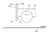
- FIG. 1 is a schematic perspective view of a light irradiation apparatus according to an embodiment.
- FIG. 2 is a schematic side view of one lamp of the light irradiation apparatus according to the embodiment.
- a plurality of circular lamps 101 are arranged.
- the lamp 101 is supported by a lamp holder 102.
- the lamp holder 102 is a member that also serves as an external electrode of the lamp 101. For this reason, the lamp holder 102 is in contact with the lamp 101.
- a plurality of gas supply pipes 103 are provided on the side surface of the lamp holder 102.
- two gas pipes 103a and 103b are provided in the gas supply pipe 103.
- a nozzle is provided as a gas injection section at the tip of each of the gas pipes 103a and 103b (see FIG. 2).
- the nozzles are a first nozzle 110 (first gas injection unit) and a second nozzle 120 (second gas injection unit).
- Each of the first nozzle 110 and the second nozzle 120 preferably has a shape having a slit-like opening continuous in the longitudinal direction of the lamp 101.
- the first nozzle 110 and the second nozzle 120 may be nozzles in which a plurality of openings are arranged in the longitudinal direction of the lamp 101, or a change plate that changes the gas flow. It may be. These nozzle shapes will be described later.
- the gas supply pipes 103 are aggregated and finally connected to a gas supply source (not shown).
- the supplied gas is preferably a gas that does not react with an object to be described later and does not absorb ultraviolet light.
- a gas that does not react with an object to be described later and does not absorb ultraviolet light.
- examples of such a gas include nitrogen gas and inert (such as helium and argon) gas.
- the gas supply source is a gas cylinder of these gases.
- a gas flow meter, a flow rate control valve (both not shown) and the like are arranged in the middle of these.
- a booster pump (not shown) may be provided in the middle of these.
- the first nozzle 110 and the second nozzle 120 are provided in the gas pipes 103 a and 103 b, respectively, but instead of this, one gas pipe is branched immediately before the nozzle and the first nozzle 110 and the second nozzle 120 are provided. Gas may be distributed to the second nozzle 120.
- the light irradiation apparatus 100 is provided with a plurality of rollers 150 for moving (also referred to as conveying) the workpiece 200 under the lamp 101.
- the workpiece 200 is moved in a direction (for example, a vertical direction) that intersects the longitudinal direction of the lamp 101.
- the roller 150 is rotatable and is driven as the workpiece 200 moves.
- the workpiece 200 moves under the lamp 101 when the workpiece 200 is wound up by a winder (not shown). Note that all or some of the plurality of rollers 150 may be connected to a power source and rotate to assist the movement of the workpiece 200.
- the lamp 101 various lamps 101 are used according to the purpose of processing the workpiece 200.
- the lamp 101 to be used is an ultraviolet lamp.
- the lamp shape is tubular or torus (tubular is shown in the drawings of the present embodiment).
- a spherical lamp 101 can be used.
- a shape in which the gas flow from the nozzle is disturbed is not preferable.
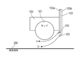
- a virtual line connecting the center of the lamp 101 and the workpiece 200 at the shortest distance is set here. This is the reference line.
- the right side in the figure is the first side and the left side is the second side so that the reference line is the center line and the line is symmetrical.
- the first nozzle 110 and the second nozzle 120 are both installed on the same side (here, the first side).
- the installation side may be upstream or downstream in relation to the moving direction of the workpiece 200.
- the first nozzle 110 is installed at a position where the gas (first gas flow) is directly sprayed toward the lamp 101, and the second nozzle 120 directly sprays the gas (second gas flow) toward the workpiece 200. It is installed at the position to attach.
- the second nozzle 120 is provided at a position closer to the workpiece 200 than the first nozzle 110. Thereby, the center of the gas injection direction from the first nozzle 110 and the center of the gas injection direction from the second nozzle 120 do not intersect each other.
- the positional relationship between the first nozzle 110 and the second nozzle 120 and the lamp 101 does not significantly block the light emitted from the lamp 101 in consideration of the size of the first nozzle 110, the second nozzle 120 and the gas supply pipe 103. Install in position.
- the relative speed with respect to the lamp 101 hereinafter simply referred to as the relative speed
- the integrated light quantity (J / cm 2 ) received by the workpiece surface is not nozzle-installed. It is preferable that B / A ⁇ 0.8, where A is the value of A and B is the value after the nozzle is installed.
- the light quantity received by the workpiece 200 is set at a position where 80% or more can be secured when the nozzle is installed compared to when the nozzle is not installed.
- the integrated light quantity does not extremely decrease compared to the case where both nozzles are not installed. For this reason, compared with the case where no nozzle is installed, it is not necessary to take a measure such as lowering the moving speed, and the productivity is not affected.
- imaginary lines are set to represent the gas injection angles of the first nozzle 110 and the second nozzle 120, respectively.
- the imaginary line is a parallel line drawn in parallel with the reference line in the direction of the workpiece 200 from the respective injection ports of the first nozzle 110 and the second nozzle 120.
- a line drawn in parallel to the reference line from the ejection port of the first nozzle 110 in the direction of the workpiece 200 is defined as a first parallel line, and parallel to the reference line in the direction of the workpiece 200 from the ejection port of the second nozzle 120.
- the line drawn to is defined as the second parallel line.
- the angle formed by the gas injection direction of the first nozzle 110 and the first parallel line is ⁇ .
- the angle ⁇ formed is positive in the direction opening from the first parallel line toward the lamp 101.
- This angle ⁇ is the gas injection angle of the first nozzle 110.
- the allowable range of the angle ⁇ is different depending on the size of the lamp 101 and the distance between the lamp 101 and the first nozzle 110. In other words, the allowable range of the angle ⁇ is such that if the size of the lamp 101 is the same, the allowable range of the angle ⁇ increases if the distance between the lamp 101 and the first nozzle 110 is short, and the angle formed if the distance is long.
- the allowable range of ⁇ becomes smaller.
- the gas injection direction center from the first nozzle 110 can be directed toward the lamp 101 if the angle ⁇ is about 60 degrees. If the first nozzle 110 is installed away from the lamp 101, the angle ⁇ may be set to 120 degrees. In such an angle range, the center of the gas injection direction from the first nozzle 110 faces the lamp 101 direction. That is, within such an angle range, the first nozzle 110 is installed at a position that does not block the irradiated light, and the gas ejected from the first nozzle 110 can be directly sprayed toward the lamp 101. it can. Moreover, a laminar flow along the lamp tube surface can be generated.
- the angle between the gas injection direction of the second nozzle 120 and the second parallel line is ⁇ .
- the angle ⁇ formed is positive in the direction from the second parallel line toward the lamp 101.
- This angle ⁇ is the gas injection angle of the second nozzle 120.
- the formed angle ⁇ is preferably more than 0 degree and 90 degrees or less.
- the gas ejected from the second nozzle 120 can be directly sprayed in the direction of the workpiece 200, and the second nozzle 120 can be installed without blocking the irradiated light.
- a laminar flow can be generated between the lamp 101 and the workpiece 200. More preferably, the angle is 20 degrees or more and 90 degrees or less. By setting the angle range, a laminar flow can be generated in the vicinity of the workpiece 200 between the lamp 101 and the workpiece 200.
- the gas flow rate from each nozzle is not particularly limited as long as two gas flows can be generated between the lamp 101 and the workpiece 200. Therefore, if the flow rate is too low, a gas flow cannot be created. On the other hand, if it is unnecessarily too much, there is no meaning because the effect of suppressing lamp contamination with respect to the amount of gas consumption is not improved.
- the gas flow rates of the first nozzle 110 and the second nozzle 120 are about 0.02 to 4.0 (m 3 / min) in terms of 1 m of the light emission effective length (width) of the lamp 101. It is preferable that Note that the gas flow rates of the first nozzle 110 and the second nozzle 120 are preferably set to be the same as much as possible.
- the gas flow rate from one nozzle is too high, the balance is poor and the two gas flows cannot be formed well.
- the other is preferably 50% or more, and more preferably, the gas flow rates of both are the same.
- the first nozzle 110 and the second nozzle 120 are configured to inject gas perpendicular to the longitudinal direction of the lamp 101.
- FIG. 3 is a schematic perspective view for explaining a gas injection port of the nozzle. This figure is a schematic perspective view of the lamp direction as viewed from the workpiece side.
- each of the first nozzle 110 and the second nozzle 120 has one rectangular opening extending over the entire length (light emission effective length) in the lamp longitudinal direction. That is, the shape looks like a slit when only the nozzle outlet is viewed. If the nozzle has such a slit-like opening, the first nozzle 110 can inject gas at a substantially uniform flow rate onto the surface of the lamp tube. Similarly, the second nozzle 120 can inject gas to the object to be processed at a substantially uniform flow rate. Therefore, it is most preferable that the first nozzle 110 and the second nozzle 120 each have one slit-shaped opening.
- the spray diffusion angle (so-called spray angle) in the direction orthogonal to the lamp longitudinal direction of each nozzle does not need to be widened, and about 0 to 45 degrees is sufficient.
- the spray angle in the lamp longitudinal direction gas diffusion at the end in the longitudinal direction of the slit
- the spray angle in the longitudinal direction of the lamp may be about 0 to 45 degrees, for example.
- a plurality of gas pipes 103a and 103b are provided for the first nozzle 110 and the second nozzle 120 having one slit-like opening (see FIG. 1).
- the number of gas pipes 103a and 103b varies depending on the length in the lamp longitudinal direction and is not particularly limited.
- the gas may be ejected at a substantially uniform flow rate by a slit-like opening nozzle using a single gas pipe.
- several to several tens of gas pipes may be used accordingly.
- the variation in the gas flow rate injected from the slit-shaped opening is within a certain range.
- the flow rate at the position with the highest gas flow rate is 100%, it is preferable that the flow rate at the position with the minimum gas flow rate be 50% or more. More preferably, the minimum gas flow rate is 80% or more.
- each nozzle 110 and 120 can be 80% or more when the effective light emission length of the lamp 101 is 100%. preferable. By setting it as such a range, the lamp
- the opening height of each of the nozzles 110 and 120 (in the direction orthogonal to the light emission effective length of the lamp 101) is, for example, 0.05 to 2 mm, preferably 0.1 to 1 mm.
- the 1st nozzle 110 and the 2nd nozzle 120 can inject a gas so that a laminar flow (detailed later) may be produced in a ramp direction and a to-be-processed object direction, respectively.
- FIG. 4 is a schematic perspective view for explaining a gas injection port of another nozzle. This figure is a schematic perspective view of the lamp direction as viewed from the workpiece side.
- the first nozzle 110 and the second nozzle 120 may be composed of a plurality of independent nozzles as shown in FIG. That is, the first nozzle 110 includes nozzles 1101 to 1107, and the second nozzle 120 includes nozzles 1201 to 1207.
- the openings of the nozzles 1101 to 1107 and the nozzles 1201 to 1207 have an elliptical shape in which the longitudinal direction of the lamp 101 has a major axis.
- the number of nozzles 1101 to 1107 and nozzles 1201 to 1207 may be set so that gas can be injected at a substantially uniform flow rate over the effective light emission length. For this reason, as in the case of the slit shape, the plurality of nozzles 1101 to 1107 and the nozzles 1201 to 1207 are installed so that gas can be sprayed to 80% or more of the effective light emission length of the lamp 101. Also, in this case, the variation in the flow rate of the injected gas is 50% or more even at the position where the gas flow rate is the minimum, for example, when the flow rate at the position where the gas flow rate is the highest is 100%, as in the case of the slit shape. It is preferable to do so. More preferably, the minimum gas flow rate is 80% or more.
- the gas injection diffusion angle (spray angle) of each nozzle in the nozzles 1101 to 1107 and the nozzles 1201 to 1207 is, for example, slightly widened in the lamp longitudinal direction. Thereby, the variation in the gas flow rate is suppressed.
- the spray angle of each nozzle is preferably about 5 to 120 degrees. Thereby, gas can be injected at a substantially uniform flow rate over the entire length of the light emission effective length of the lamp 101.
- the spray angle in the direction crossing the lamp longitudinal direction is sufficient to be about 0 to 45 degrees as in the case of the slit shape.
- each nozzle showed the case of the ellipse here, you may make it have circular or a rectangular opening, for example.
- FIG. 5 is a side view showing an example using a gas flow direction changing plate for changing the direction of gas flow.
- gas pipes 103a and 103b are provided.
- the gas pipes 103a and 103b are both straight pipes and have openings in the direction of the object to be processed (downward direction in the figure).
- a first gas flow direction changing plate 111 is provided at the opening of the gas pipe 103a
- a second gas flow direction changing plate 121 is provided at the opening of the gas pipe 103b.
- the first gas flow direction changing plate 111 is a first gas injection unit
- the second gas flow direction changing plate 121 is a second gas injection unit.
- the first gas flow direction changing plate 111 changes the direction in which the gas from the gas pipe 103a is directly sprayed onto the lamp 101.
- the first gas flow direction changing plate 111 can directly spray the gas from the gas pipe 103a onto the lamp 101 by attaching a plate-like member at the same angle as that of the first nozzle 110.
- the second gas flow direction changing plate 121 changes the direction in which the gas from the gas pipe 103 b is directly sprayed onto the workpiece 200.
- the second gas flow direction changing plate 121 can spray the gas from the gas pipe 103 b directly onto the workpiece 200 by attaching a plate-like member at the same angle as that of the second nozzle 120.
- the first gas flow direction change plate 111 and the second gas flow direction change plate 121 have a plurality of gas pipes 103 a provided in the longitudinal direction of the lamp 101, and a single first gas flow direction in the longitudinal direction. It is preferable to provide a single second gas flow direction changing plate 121 in the longitudinal direction with respect to the changing plate 111, similarly to a plurality of gas pipes 103b provided in the longitudinal direction of the lamp 101. As a result, the gas can be injected at a substantially uniform flow rate over the entire length of the effective light emission length of the lamp 101.
- first gas flow direction changing plate 111 and the second gas flow direction changing plate 121 may be provided in the gas pipes 103a and 103b, respectively.
- first gas flow direction changing plate 111 and the second gas flow direction changing plate 121 are provided so that the gas can be injected at a substantially uniform flow rate over the entire length of the light emission effective length of the lamp 101.
- FIG. 5 is drawn so that the first gas flow direction changing plate 111 and the second gas flow direction changing plate 121 come to positions opposite to those in FIG. 2.
- the first gas flow direction changing plate 111 and the second gas flow direction changing plate 121 may be arranged on either side of the lamp 101.
- the first nozzle 110 and the second nozzle 120 described above may be arranged on either side of the lamp 101 in the same manner.
- each gas injection portion may be any shape as long as the gas can be injected at a substantially uniform flow rate over the entire length of the effective light emission length. , Not limited.
- FIG. 6 is a side view for explaining the action of the nozzle. The same effect is obtained when a gas flow direction changing plate is used.
- the first nozzle 110 generates a laminar flow (first gas flow indicated by an arrow a) in the vicinity of the surface of the lamp tube by spraying gas directly onto the lamp 101.
- the first gas flow a excludes sublimates (including other scattered matter, the same applies hereinafter) that has arrived near the lamp tube surface from the vicinity of the lamp tube surface, and suppresses adhesion to the lamp tube surface.
- the second nozzle 120 generates a laminar flow (second gas flow indicated by an arrow b) in the vicinity of the surface of the workpiece 200 by spraying gas directly toward the workpiece 200.
- This second gas flow b quickly blows up the sublimate that has risend and suppresses flying near the lamp.
- the gas ejected by the second nozzle 120 will soar the sublimate from the surface of the workpiece 200, but the sublimate remarkablyd by spraying from one direction flows in a certain direction. Can be eliminated.
- the laminar flow by the first nozzle 110 prevents adhesion to the lamp tube surface.
- the object 200 in the present embodiment is a sheet-like, band-like, or plate-like member containing a silicon oxide precursor or silicon oxynitride precursor that is cured by, for example, ultraviolet irradiation on a substrate.
- a silicon oxide precursor or silicon oxynitride precursor that is cured by, for example, ultraviolet irradiation on a substrate.
- An example of such a member is a gas barrier film.
- the gas barrier film is modified by applying a silicon oxide precursor or silicon oxynitride precursor on the film substrate, and curing the silicon oxide precursor or silicon oxynitride precursor by UV irradiation. Thus, a gas barrier effect is imparted.
- Gas barrier films are widely used in electronic devices such as organic EL elements, liquid crystal display elements (LCD), thin film transistors, touch panels, electronic paper, solar cells (PV), and the like.
- the film substrate used for the gas barrier film examples include a metal substrate such as silicon, a glass substrate, a ceramic substrate, and a plastic film, and a plastic film is preferably used.
- the plastic film to be used is not particularly limited in material, thickness and the like as long as it can hold a gas barrier film, a hard coat layer and the like, and can be appropriately selected according to the purpose of use.
- Specific examples of the plastic film include polyester resin, methacrylic resin, methacrylic acid-maleic acid copolymer, polystyrene resin, transparent fluororesin, polyimide, fluorinated polyimide resin, polyamide resin, polyamideimide resin, and polyetherimide.
- Resin cellulose acylate resin, polyurethane resin, polyetheretherketone resin, polycarbonate resin, alicyclic polyolefin resin, polyarylate resin, polyethersulfone resin, polysulfone resin, cycloolefin copolymer, fluorene ring-modified polycarbonate resin, alicyclic ring
- thermoplastic resins such as modified polycarbonate resins, fluorene ring-modified polyester resins, and acryloyl compounds.
- the film substrate is preferably made of a heat resistant material. Specifically, a resin film substrate having a linear expansion coefficient of 15 ppm / K or more and 100 ppm / K or less and a glass transition temperature (Tg) of 100 ° C. or more and 300 ° C. or less is used.
- Tg glass transition temperature
- the resin film substrate satisfies the requirements for use as a laminated film for electronic parts and displays.
- the gas barrier film may be exposed to a process of 150 ° C. or higher.
- the linear expansion coefficient of the film base material in the gas barrier film exceeds 100 ppm / K, the substrate dimensions are not stable when the gas barrier film is passed through the temperature process as described above, and the thermal expansion and contraction occur. Inconvenience that the shut-off performance is deteriorated and inconvenience of being unable to withstand the heat process are likely to occur. If it is less than 15 ppm / K, the film may break like glass and the flexibility may deteriorate.
- Polyolefin for example, ZEONOR (registered trademark) 1600: 160 ° C) manufactured by Nippon Zeon Co., Ltd., polyarylate (PAr: 210 ° C), polyethersulfone (PES: 220 ° C), polysulfone (PSF: 190 ° C), cycloolefin Copolymer (COC: Compound described in JP-A No. 2001-150584: 162 ° C.), polyimide (for example, Neoprim (registered trademark): 260 ° C. manufactured by Mitsubishi Gas Chemical Co., Inc.), fluorene ring-modified polycarbonate (BCF-PC: special Open 2000-227 No.
- gas barrier films are used in combination with polarizing plates.
- the gas barrier film of the gas barrier film is arranged so as to face the inside of the cell, and arranged on the innermost side (adjacent to the element).
- the retardation value of the gas barrier film is important.
- the usage form of the gas barrier film in such an embodiment is as follows: a gas barrier film using a film substrate having a retardation value of 10 nm or less and a circularly polarizing plate (1 ⁇ 4 wavelength plate + (1/2 wavelength plate) + straight line. It is preferable to use a linear polarizing plate in combination with a gas barrier film using a film substrate having a retardation value of 100 nm to 180 nm, which can be used as a quarter wavelength plate. .
- Examples of the film substrate having a retardation of 10 nm or less include, for example, cellulose triacetate (Fuji Film Co., Ltd .: Fujitac (registered trademark)), polycarbonate (Teijin Chemicals Co., Ltd .: Pure Ace (registered trademark), Kaneka Corporation): Elmec (registered trademark)), cycloolefin polymer (manufactured by JSR Corporation: Arton (registered trademark), Nippon Zeon Corporation: ZEONOR (registered trademark)), cycloolefin copolymer (manufactured by Mitsui Chemicals, Inc .: APPEL (registered trademark)) (Pellets), manufactured by Polyplastics Co., Ltd .: Topas (registered trademark) (pellets)), polyarylate (manufactured by Unitika Co., Ltd .: U100 (pellets)), transparent polyimide (manufactured by Mitsubishi Gas Chemical Co., Ltd .
- a film base material adjusted to a desired retardation value by appropriately stretching the above film base material can be used.
- the plastic film is preferably transparent. That is, the light transmittance is usually 80% or more, preferably 85% or more, and more preferably 90% or more.
- the light transmittance is calculated by measuring the total light transmittance and the amount of scattered light using the method described in JIS K7105: 1981, that is, using an integrating sphere light transmittance measuring device, and subtracting the diffuse transmittance from the total light transmittance. can do.
- an opaque material can be used as the plastic film. Examples of the opaque material include polyimide, polyacrylonitrile, and known liquid crystal polymers.
- the thickness of the plastic film used as the base material of the gas barrier film is not particularly limited because it is appropriately selected depending on the use, but is typically 1 to 800 ⁇ m, preferably 10 to 200 ⁇ m.
- These plastic films may have functional layers such as a transparent conductive layer and a primer layer.
- As the functional layer in addition to those described above, those described in paragraph numbers 0036 to 0038 of JP-A-2006-289627 can be preferably employed.
- the substrate preferably has a high surface smoothness.
- the surface smoothness those having an average surface roughness (Ra) of 2 nm or less are preferable. Although there is no particular lower limit, it is practically 0.01 nm or more. If necessary, both surfaces of the base material, at least the side on which the gas barrier film is provided, may be polished to improve smoothness.
- the base material using the above-described resins or the like may be an unstretched film or a stretched film.
- silicon oxide precursors or silicon oxynitride precursors include, for example, perhydropolysilazane, organopolysilazane, silsesquioxane, tetramethylsilane, and trimethylmethoxysilane.
- polysilazanes such as perhydropolysilazane and organopolysilazane; polysiloxanes such as silsesquioxane, and the like are preferable in terms of film formation, fewer defects such as cracks, and less residual organic matter.
- Polysilazane is more preferable, and perhydropolysilazane is particularly preferable because the performance is high and the barrier performance is maintained even when bent and under high temperature and high humidity conditions.
- Polysilazane is a polymer having a silicon-nitrogen bond, having a bond such as Si—N, Si—H, and N—H, and a precursor such as SiO 2 , Si 3 N 4 , and both intermediate solid solutions SiOxNy, etc. It is an inorganic polymer that becomes the body.
- the polysilazane preferably has the following structure.
- R 1 , R 2 and R 3 are each independently a hydrogen atom, a substituted or unsubstituted alkyl group, aryl group, vinyl group or (trialkoxysilyl) alkyl group. .
- R 1 , R 2 and R 3 may be the same or different.
- examples of the alkyl group include linear, branched or cyclic alkyl groups having 1 to 8 carbon atoms.
- the aryl group include aryl groups having 6 to 30 carbon atoms.
- non-condensed hydrocarbon groups such as phenyl group, biphenyl group, terphenyl group; pentarenyl group, indenyl group, naphthyl group, azulenyl group, heptaenyl group, biphenylenyl group, fluorenyl group, acenaphthylenyl group, preadenenyl group , Condensed polycyclic hydrocarbon groups such as acenaphthenyl group, phenalenyl group, phenanthryl group, anthryl group, fluoranthenyl group, acephenanthrenyl group, aceantrirenyl group, triphenylenyl group, pyrenyl group, chrysenyl group, naphthacenyl group, etc.
- non-condensed hydrocarbon groups such as phenyl group, biphenyl group, terphenyl group; pentarenyl group, indenyl group, nap
- the (trialkoxysilyl) alkyl group includes an alkyl group having 1 to 8 carbon atoms having a silyl group substituted with an alkoxy group having 1 to 8 carbon atoms. More specific examples include 3- (triethoxysilyl) propyl group and 3- (trimethoxysilyl) propyl group.
- the substituent optionally present in R 1 to R 3 is not particularly limited, and examples thereof include an alkyl group, a halogen atom, a hydroxyl group (—OH), a mercapto group (—SH), a cyano group (—CN), There are a sulfo group (—SO 3 H), a carboxyl group (—COOH), a nitro group (—NO 2 ) and the like. Note that the optionally present substituent is not the same as R 1 to R 3 to be substituted. For example, when R 1 to R 3 are alkyl groups, they are not further substituted with alkyl groups.
- R 1 , R 2 and R 3 are preferably a hydrogen atom, a methyl group, an ethyl group, a propyl group, an isopropyl group, a butyl group, an isobutyl group, a tert-butyl group, a phenyl group, a vinyl group, 3 -(Triethoxysilyl) propyl group or 3- (trimethoxysilylpropyl) group.
- n is an integer
- the polysilazane having the structure represented by the general formula (I) is determined to have a number average molecular weight of 150 to 150,000 g / mol. preferable.
- one of preferred embodiments is perhydropolysilazane in which all of R 1 , R 2 and R 3 are hydrogen atoms.
- polysilazane has a structure represented by the following general formula (II).
- R 1 ′ , R 2 ′ , R 3 ′ , R 4 ′ , R 5 ′ and R 6 ′ are each independently a hydrogen atom, a substituted or unsubstituted alkyl group, An aryl group, a vinyl group or a (trialkoxysilyl) alkyl group.
- R 1 ′ , R 2 ′ , R 3 ′ , R 4 ′ , R 5 ′ and R 6 ′ may be the same or different.
- the substituted or unsubstituted alkyl group, aryl group, vinyl group or (trialkoxysilyl) alkyl group in the above is the same as the definition of the general formula (I), and thus the description is omitted.
- n ′ and p are integers, and the polysilazane having the structure represented by the general formula (II) is determined to have a number average molecular weight of 150 to 150,000 g / mol. It is preferred that Note that n ′ and p may be the same or different.
- R 1 ′ , R 3 ′ and R 6 ′ each represent a hydrogen atom, and R 2 ′ , R 4 ′ and R 5 ′ each represent a methyl group;
- R 1 ' , R 3' and R 6 ' each represents a hydrogen atom, R 2' , R 4 ' each represents a methyl group, and R 5' represents a vinyl group;
- R 1 ' , R 3' , R 4 A compound in which ' and R 6' each represent a hydrogen atom and R 2 ' and R 5' each represents a methyl group is preferred.
- polysilazane has a structure represented by the following general formula (III).
- R 1 ′′ , R 2 ′′ , R 3 ′′ , R 4 ′′ , R 5 ′′ , R 6 ′′ , R 7 ′′ , R 8 ′′ and R 9 ′′ are each independently A hydrogen atom, a substituted or unsubstituted alkyl group, aryl group, vinyl group or (trialkoxysilyl) alkyl group, wherein R 1 ′′ , R 2 ′′ , R 3 ′′ , R 4 ′′ , R 5 ′′ , R 6 ′′ , R 7 ′′ , R 8 ′′ and R 9 ′′ may be the same or different.
- the substituted or unsubstituted alkyl group, aryl group, vinyl group or (trialkoxysilyl) alkyl group in the above is the same as the definition of the general formula (I), and thus the description is omitted.
- n ′′, p ′′ and q are integers, and the polysilazane having the structure represented by the general formula (III) has a number average molecular weight of 150 to 150,000 g / mol. It is preferable to be determined as follows. Note that n ′′, p ′′, and q may be the same or different.
- R 1 ′′ , R 3 ′′ and R 6 ′′ each represent a hydrogen atom
- R 2 ′′ , R 4 ′′ , R 5 ′′ and R 8 ′′ each represent a methyl group.
- R 9 ′′ represents a (triethoxysilyl) propyl group
- R 7 ′′ represents an alkyl group or a hydrogen atom.
- the organopolysilazane in which a part of the hydrogen atom portion bonded to Si is substituted with an alkyl group or the like has improved adhesion to the base material as a base by having an alkyl group such as a methyl group and is hard.
- the ceramic film made of brittle polysilazane can be toughened, and there is an advantage that the occurrence of cracks can be suppressed even when the (average) film thickness is increased. For this reason, perhydropolysilazane and organopolysilazane may be selected as appropriate according to the application, and may be used in combination.
- Perhydropolysilazane is presumed to have a linear structure and a ring structure centered on 6- and 8-membered rings.
- the number average molecular weight (Mn) is about 600 to 2000 (polystyrene conversion), and there are liquid or solid substances, and the state varies depending on the molecular weight.
- polysilazane examples include, but are not limited to, for example, silicon alkoxide-added polysilazane obtained by reacting the above polysilazane with silicon alkoxide (Japanese Patent Laid-Open No.
- glycidol addition obtained by reacting glycidol Polysilazane (JP-A-6-122852), alcohol-added polysilazane obtained by reacting an alcohol (JP-A-6-240208), metal carboxylate-added polysilazane obtained by reacting a metal carboxylate 6-299118), acetylacetonate complex-added polysilazane obtained by reacting a metal-containing acetylacetonate complex (JP-A-6-306329), metal fine particle-added polysilazane obtained by adding metal fine particles (specialty) Kaihei 7 Publication), etc.
- No. 196,986 include polysilazane ceramic at low temperatures.
- the precursor as described above is prepared as a coating liquid for forming a coating film (hereinafter also referred to as a coating liquid for forming a coating film).
- the solvent used for the preparation is not particularly limited as long as it can dissolve the precursor, but does not include water and reactive groups (for example, hydroxyl group or amine group) that easily react with the precursor.
- An organic solvent inert to the precursor is preferable, and an aprotic organic solvent is more preferable.
- an aprotic solvent for example, carbonization of aliphatic hydrocarbons, alicyclic hydrocarbons, aromatic hydrocarbons such as pentane, hexane, cyclohexane, toluene, xylene, solvesso, turben, etc.
- Hydrogen solvents Halogen hydrocarbon solvents such as methylene chloride and trichloroethane; Esters such as ethyl acetate and butyl acetate; Ketones such as acetone and methyl ethyl ketone; Aliphatic ethers such as dibutyl ether, dioxane and tetrahydrofuran; Alicyclic ethers and the like Ethers: Examples include tetrahydrofuran, dibutyl ether, mono- and polyalkylene glycol dialkyl ethers (diglymes), and the like.
- the solvent is selected according to purposes such as the solubility of the precursor and the evaporation rate of the solvent, and may be used alone or in the form of a mixture of two or more.
- the concentration of the precursor in the coating solution for coating film formation is not particularly limited, and varies depending on the film thickness of the gas barrier film and the pot life of the coating solution, but is preferably 1 to 80% by weight, more preferably 5 to 50% by weight. More preferably, it is 10 to 40% by weight.
- the coating liquid for forming a coating film preferably contains a catalyst in order to promote reforming.
- catalysts include N, N-diethylethanolamine, N, N-dimethylethanolamine, triethanolamine, triethylamine, 3-morpholinopropylamine, N, N, N ′, N′-tetramethyl- 1,3-diaminopropane, amine compounds such as N, N, N ′, N′-tetramethyl-1,6-diaminohexane, Pt compounds such as Pt acetylacetonate, Pd compounds such as propionic acid Pd, Rh acetyl Metal catalysts such as Rh compounds such as acetonate, N-heterocyclic compounds, pyridine compounds such as pyridine, ⁇ -picoline, ⁇ -picoline, ⁇ -picoline, piperidine, lutidine, pyrimidine, pyridazine, DBU (1,8- Diazabicyclo [
- the concentration of the catalyst added at this time is preferably in the range of 0.1 to 10% by weight, more preferably 0.5 to 7% by weight, based on polysilazane. By setting the addition amount of the catalyst within this range, it is possible to avoid excessive silanol formation due to rapid progress of the reaction, decrease in film density, increase in film defects, and the like.
- the following additives can be used as necessary.
- cellulose ethers, cellulose esters for example, ethyl cellulose, nitrocellulose, cellulose acetate, cellulose acetobutyrate, etc.
- natural resins for example, rubber, rosin resin, etc., synthetic resins
- Aminoplasts especially urea resins, melamine formaldehyde resins, alkyd resins, acrylic resins, polyesters or modified polyesters, epoxides, polyisocyanates or blocked polyisocyanates, polysiloxanes, and the like.
- a conventionally known appropriate wet coating method can be employed as a method of applying the coating liquid for forming a coating film.
- a spin coating method a roll coating method, a flow coating method, an ink jet method, a spray coating method, a printing method, a dip coating method, a casting film forming method, a bar coating method, and a gravure printing method.
- the coating thickness can be appropriately set according to the purpose.
- the coating thickness per gas barrier film is preferably about 5 to 500 nm, more preferably 10 to 400 nm after drying. If the film thickness is 5 nm or more, sufficient barrier properties can be obtained, and if it is 500 nm or less, stable coating properties can be obtained at the time of coating film formation, and high light transmittance can be realized.
- the coating film After applying the coating solution, it is preferable to dry the coating film.
- the organic solvent contained in the coating film can be removed. At this time, all of the organic solvent contained in the coating film may be dried or may be partially left. Even when a part of the organic solvent is left, a suitable gas barrier film can be obtained. The remaining solvent can be removed later.
- the drying temperature of the coating film varies depending on the substrate to be applied, but is preferably 50 to 200 ° C.
- the drying temperature is preferably set to 150 ° C. or less in consideration of deformation of the substrate due to heat.
- the temperature can be set by using a hot plate, oven, furnace or the like.
- the drying time is preferably set to a short time. For example, when the drying temperature is 150 ° C., the drying time is preferably set within 30 minutes.
- the drying atmosphere may be any condition such as an air atmosphere, a nitrogen atmosphere, an argon atmosphere, a vacuum atmosphere, or a reduced pressure atmosphere with a controlled oxygen concentration.
- the coating film obtained by applying the coating solution for forming the upper coating film may include a step of removing moisture before or during the modification treatment.
- a form of dehumidification while maintaining a low humidity environment is preferable. Since humidity in a low-humidity environment varies depending on temperature, a preferable form is shown for the relationship between temperature and humidity by defining the dew point temperature.
- the preferable dew point temperature is 4 ° C. or less (temperature 25 ° C./humidity 25%), the more preferable dew point temperature is ⁇ 5 ° C. (temperature 25 ° C./humidity 10%) or less, and the maintaining time depends on the film thickness of the gas barrier film. It is preferable to set appropriately.
- the dew point temperature is ⁇ 5 ° C. or less and the maintaining time is 1 minute or more.
- the lower limit of the dew point temperature is not particularly limited, but is usually ⁇ 50 ° C. or higher, and preferably ⁇ 40 ° C. or higher. This is a preferred form from the viewpoint of promoting the dehydration reaction of the gas barrier film by removing water before or during the reforming process.
- Polysilazane which is a preferred precursor, is commercially available in a solution state dissolved in an organic solvent, and a commercially available product can be used as it is as a coating solution for coating film formation.
- examples of commercially available polysilazane solutions include NN120-10, NN120-20, NAX120-20, NN110, NN310, NN320, NL110A, NL120A, NL120-20, NL150A, NP110, NP140, and SP140 manufactured by Merck Performance Materials. Can be mentioned.
- the irradiation is performed by irradiating ultraviolet rays using the light irradiation apparatus according to the present embodiment.
- light energy having a wavelength component of less than 200 nm, which is larger than the interatomic bonding force in silicon oxide or silicon oxynitride, and preferably using ultraviolet light containing a wavelength component of 100 to 180 nm is used for photon process of bonding atoms.
- a silicon oxide film and / or silicon oxynitride film is formed at a relatively low temperature (about 200 ° C. or less) by causing an oxidation reaction with active oxygen or ozone to proceed while cutting directly by the action of photons only. I do.
- any light source that generates ultraviolet light including a wavelength component of less than 200 nm may be used.
- Excimer radiators eg, excimer lamps such as Xe excimer lamps having maximum emission at about 172 nm, ArF excimer lamps having maximum emission at about 193 nm, ArBr excimer lamps having maximum emission at about 161 nm
- a low-pressure mercury lamp, an amalgam lamp, a deuterium lamp, or a lamp using carbon monoxide having strong emission lines at about 156 nm and about 165 nm is used.
- a rare gas excimer lamp is particularly preferably used. Since noble gas atoms such as Xe, Kr, Ar, Ne, and the like are chemically bonded and do not form molecules, they are called inert gases. However, rare gas atoms (excited atoms) that have gained energy by discharge or the like can be combined with other atoms to form molecules. When the rare gas is xenon, e + Xe ⁇ e + Xe * Xe * + Xe + Xe ⁇ Xe 2 * + Xe, and excimer light of 172 nm is emitted when the excited excimer molecule Xe 2 * transitions to the ground state.
- ⁇ Excimer lamps are characterized by high efficiency because radiation concentrates on one wavelength and almost no other light is emitted. Further, since no extra light is emitted, the temperature of the object can be kept low. Furthermore, since no time is required for starting and restarting, instantaneous lighting and blinking are possible.
- Dielectric barrier discharge is a lightning generated in a gas space by arranging a gas space between both electrodes via a dielectric (transparent quartz in the case of an excimer lamp) and applying a high frequency high voltage of several tens of kHz to the electrode.
- the discharge is called a micro discharge (micro discharge) similar to the above.
- the micro discharge streamer reaches the tube wall (dielectric)
- the electric charge accumulates on the dielectric surface, and the micro discharge disappears.
- This micro discharge spreads over the entire tube wall and repeats generation and extinction. For this reason, flickering of light that can be seen with the naked eye occurs.
- a very high temperature streamer reaches a pipe wall directly locally, there is a possibility that deterioration of the pipe wall may be accelerated.
- electrodeless field discharge is possible in addition to dielectric barrier discharge.
- Electrode-free electric field discharge by capacitive coupling also called high frequency discharge (RF (Radio Frequency) discharge.
- the lamp 101, the electrodes, and their arrangement may be basically the same as those of the dielectric barrier discharge, but the high frequency applied between the two electrodes is lit at several MHz. Since the electrodeless field discharge can obtain a spatially and temporally uniform discharge in this way, a long-life lamp 101 without flickering can be obtained.
- the outer electrode covers the entire outer surface and allows light to pass through to extract light to the outside in order to cause discharge in the entire discharge space.
- an electrode in which a fine metal wire is formed in a net shape is used. Since this electrode uses as thin a line as possible so as not to block light, it is easily damaged by ozone generated by vacuum ultraviolet light in an oxygen atmosphere.
- Synthetic quartz windows are not only expensive consumables, but also cause light loss.
- the outer diameter of the double-cylindrical lamp is about 25 mm, the difference in distance to the irradiation surface cannot be ignored directly below the lamp axis and on the side of the lamp, resulting in a large difference in illuminance. Therefore, even if the lamps 101 are arranged in close contact, a uniform illuminance distribution cannot be obtained. If the irradiation device is provided with a synthetic quartz window, the distance in the oxygen atmosphere can be made uniform, and a uniform illuminance distribution can be obtained.
- the synthetic quartz window is the lamp tube surface. Therefore, if it is contaminated with sublimates, the synthetic quartz window must be cleaned or replaced.
- the biggest feature of the capillary excimer lamp is its simple structure.
- the quartz tube is closed at both ends, and only gas for excimer light emission is sealed inside. Therefore, a very inexpensive light source can be provided.
- Double-cylindrical lamps are easily damaged by handling and transportation compared to thin-tube lamps because they are processed by connecting both ends of the inner and outer tubes.
- the outer diameter of the tube of the thin tube lamp is about 6 to 12 mm. If it is too thick, a high voltage is required for starting.
- the discharge mode can be either dielectric barrier discharge or electrodeless field discharge.
- the electrode may have a flat surface in contact with the lamp 101, but if the shape is matched to the curved surface of the lamp 101, the lamp 101 can be firmly fixed, and the discharge is more stable when the electrode is in close contact with the lamp 101. To do. Also, if the curved surface is made into a mirror surface with aluminum, it also becomes a light reflector.
- the Xe excimer lamp emits ultraviolet light having a short wavelength of 172 nm at a single wavelength, and thus has excellent luminous efficiency. Since this light has a large oxygen absorption coefficient, radical oxygen atomic species and ozone can be generated at a high concentration with a small amount of oxygen.
- the energy of light having a short wavelength of 172 nm has a high ability to dissociate organic bonds.
- the coating film can be modified in a short time by the high energy of the active oxygen, ozone and ultraviolet radiation.
- ⁇ Excimer lamps have high light generation efficiency and can be lit with low power.
- light having a long wavelength that causes a temperature increase due to light is not emitted, and energy is irradiated in the ultraviolet region, that is, in a short wavelength, so that the increase in the surface temperature of the target object is suppressed.
- it is suitable for flexible film materials such as PET that are easily affected by heat.
- the lamp 101 by these dielectric barrier discharge or electrodeless electric field discharge is preferably used.
- Oxygen is required for the reaction at the time of irradiation, but ultraviolet light containing a wavelength component of 200 nm or less is easily absorbed because it is absorbed by oxygen. Therefore, irradiation is performed with oxygen concentration and water vapor concentration as much as possible. It is preferable to carry out in a low state. That is, the oxygen concentration during irradiation is preferably 0.01 to 5% by volume, more preferably 0.01 to 1% by volume, and further preferably 0.01 to 0.5% by volume. preferable.
- a dry inert gas is preferable, and a dry nitrogen gas is particularly preferable from the viewpoint of cost.
- the oxygen concentration can be adjusted by measuring the flow rates of oxygen gas and inert gas introduced into the irradiation chamber and changing the flow rate ratio. In order to satisfy these conditions, in the apparatus of this embodiment, it is preferable to spray dry nitrogen gas from the first nozzle 110 and the second nozzle 120 while maintaining the oxygen concentration of the atmosphere in the apparatus within the above range.
- the peak illuminance of ultraviolet light on the coating surface that the coating film receives is preferably 50 to 500 mW / cm 2 , and more preferably 80 to 300 mW / cm 2 . If it is this range, modification
- the irradiation energy amount (irradiation amount) of ultraviolet light on the coating surface is preferably 0.01 to 20 J / cm 2 , more preferably 0.1 to 20 J / cm 2 , and 0.3 to 15 J. More preferably, it is / cm 2 . If it is this range, hardening will fully advance and productivity will improve. In addition, it is possible to prevent cracks due to excessive modification and thermal deformation of the film substrate.
- an ultraviolet irradiation process may be performed in multiple times, what is necessary is just to select the irradiation amount per time suitably so that the sum total of irradiation amount may become the said range.
- the distance between the film substrate and the ultraviolet light source and the irradiation time so long as the film substrate carrying the irradiated coating film is not damaged.
- the distance between the substrate and the ultraviolet irradiation lamp is preferably 0.01 to 10 mm from the viewpoint of suppressing light absorption by oxygen.
- the irradiation time is preferably 0.05 to 300 seconds from the viewpoint of reforming efficiency and productivity.
- ultraviolet light having a wavelength of 200 nm or more and less than 230 nm may be used for ultraviolet irradiation.
- the ultraviolet light source having such a wavelength is not limited as long as it generates ultraviolet light having a wavelength of 200 nm or more and less than 230 nm.
- a KrCl excimer lamp single wavelength of 222 nm
- a KrBr excimer lamp 207 nm
- AlGaN Although the LED element etc. which used AlN are mentioned, it is not specifically limited.
- a phosphor is provided inside the glass tube of the Xe excimer lamp (for example, Japanese Patent Application Laid-Open No. 2011-175823), or ultraviolet light having the wavelength is generated through a filter provided with a phosphor between the Xe excimer lamp and the coating film. Can do.
- oxygen is required, and the oxygen concentration at the time of irradiation is preferably 0.01 to 21% by volume, more preferably 0.1 to 21% by volume. If it is this range, the modification
- the gas satisfying the irradiation atmosphere is preferably a dry inert gas, and particularly preferably a dry nitrogen gas from the viewpoint of cost.
- the oxygen concentration can be adjusted by measuring the flow rates of oxygen gas and inert gas introduced into the irradiation chamber and changing the flow rate ratio.
- the dry nitrogen gas is supplied to the first nozzle 110 and the second nozzle while maintaining the oxygen concentration in the atmosphere in the apparatus in the above range. It may be sprayed from the nozzle 120.
- the peak illuminance of the ultraviolet light on the coating surface received by the coating film is preferably 10 to 500 mW / cm 2 , more preferably 50 to 300 mW / cm 2. preferable. If it is this range, hardening will be attained to the deep part of a coating film. Further, the irradiation energy amount (irradiation amount) of ultraviolet light on the coating surface is preferably 0.01 to 20 J / cm 2 , more preferably 0.1 to 15 J / cm 2 , and 0.3 More preferably, it is ⁇ 10 J / cm 2 . If it is this range, hardening will fully advance and productivity will improve.
- the ultraviolet irradiation may be performed a plurality of times.
- the irradiation amount per time may be appropriately selected so that the total irradiation amount falls within the above range.
- the distance between the substrate and the ultraviolet irradiation lamp is preferably 0.01 to 100 mm from the viewpoint of suppressing light absorption by oxygen.
- the irradiation time is preferably 0.05 to 300 seconds from the viewpoint of reforming efficiency and productivity.
- the distance between the lamp 101, which is an ultraviolet light source, and the workpiece 200 may be set so as to be the above-mentioned ultraviolet irradiation energy, and is not particularly limited, but is preferably 5 to 50 mm, for example.
- the lamps 101 are installed at regular intervals (for example, at intervals of 5 to 200 mm) in the moving direction of the workpiece 200. At this time, the number of lamps 101 installed differs depending on the relative speed with the workpiece 200. If the lamp illuminance is the same, if the number of lamps 101 is small, the relative speed is slowed down, which is necessary for curing. When the number of lamps 101 is large, the throughput can be increased by increasing the relative speed.
- a light irradiation device with one excimer lamp was used.
- the workpiece was moved relative to the excimer lamp.
- the workpiece was moved by a roll-to-roll method.
- the structure of a light irradiation apparatus and a to-be-processed object is as follows.
- the light irradiation device has a water-cooled excimer lamp manufactured by M.D.
- the excimer lamp has an outer diameter of 20 mm ⁇ and an effective irradiation width of 500 mm.
- the tube surface illuminance was adjusted to a range of 120 ⁇ 5 mW / cm 2 at a distance of 3 mm from the tube surface of the lamp (the gap was filled with nitrogen).
- the gas injection nozzle has a slit-like (rectangular) injection port in which both the first nozzle and the second nozzle have an injection port opening of 0.5 mm in height and 500 mm in length.
- the gas used is nitrogen gas.
- the base material of the object to be processed was a PET base material (UH13 manufactured by Toray Industries Inc.) having a width of 550 mm and a thickness of 100 ⁇ m.
- polysilazane manufactured by Merck Performance Materials, NN120 was prepared by diluting to 5% by mass with dibutyl ether.
- the substrate was moved at a speed of 0.5 m / min, and an application liquid was applied to the smooth surface side of the substrate so that the dry film thickness was 100 nm using an extrusion coater.
- the application width is 500 mm. This moving speed is a condition in which, after coating, drying is performed at 50 ° C. for 10 minutes in the first drying section and then drying at 80 ° C. for 10 minutes in the second drying section.
- Nitrogen is supplied to the chamber of the light irradiation device, and the oxygen concentration in the space between the lamp tube surface and the substrate coating surface is controlled to be maintained in the range of 0.05 to 0.1% by volume. Ultraviolet irradiation was performed. At this time, the arrangement of the nozzles and the nitrogen gas flow rate were changed, and a continuous treatment of 500 m was performed so as to be an example and a comparative example. In each example and comparative example, a new lamp was used at the start.
- Lamp tube surface illuminance measurement The tube surface illuminance before and after 500 m continuous treatment was measured as follows.
- the illuminance at a distance of 3 mm from the tube surface of the lamp is measured before and after 500 m continuous processing, and the illuminance after continuous processing when the illuminance before continuous processing is taken as 100 is lamp contamination. It was used as an index.
- the illuminance was measured at a total of three points 200 mm away from the center of the lamp and left and right from the center of the lamp, and the average value of the three points was taken as the illuminance. Each measurement was performed on the portion of the lamp tube surface closest to the workpiece.
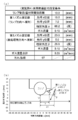
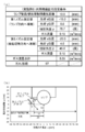
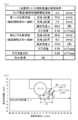
- FIGS. 7 to 26 are explanatory diagrams for explaining each example and comparative example.
- (a) is a chart showing the setting conditions and the result of the dirt index
- (b) is a workpiece. It is a figure which shows the arrangement
- the setting conditions shown in the chart of (a) are the distance between the lamp and the workpiece, the nozzle setting values (position and injection angle), and the gas flow rate.
- the position closest to the workpiece on the lamp tube surface is shown to be the origin (zero) of the two-dimensional coordinates.
- Table 1 summarizes the setting conditions of each example and comparative example and the results of the lamp contamination index.
- the setting condition outline is an outline of the setting conditions shown in FIGS. 7 to 26.
- “ ⁇ ” and “ ⁇ ” are the injection angles (the formed angle ⁇ and the formed angle ⁇ ), and the “flow rate” is The flow rate of nitrogen gas, “direction”, indicates the direction in which the gas is injected, that is, the direction of the lamp or the direction of the workpiece.
- “Arrangement” indicates whether the nozzle is arranged upstream or downstream of the lamp in the moving direction of the workpiece.
- the first nozzle and the second nozzle are installed so as to be within the range of each condition of the above-described embodiment.
- the soil index is 97 or more, which is clearly a better value than Comparative Examples 1 to 7. From this, it can be seen that lamp contamination is suppressed by forming two gas flows between the lamp and the object to be processed by two nozzles, compared to the gas flow by one nozzle.
- Comparative Example 8 the first nozzle is sprayed in the lamp direction.
- ⁇ 0 degree.
- the contamination index is 92, which is a bad result compared to Examples 1 to 4. This is presumably because the laminar flow due to the two gas flows was not successfully formed between the lamp and the workpiece because the angle of the second nozzle was perpendicular to the workpiece.
- both Comparative Examples 9 and 10 use two nozzles, both nozzles inject gas in the lamp direction or in the gas to be processed. Even in this case, the dirt index is worse than in Examples 1 to 4. From these results, it can be seen that even if two gas injection portions are provided, the effect of suppressing lamp contamination is small unless the gas is flowed so that one is in the lamp direction and the other is in the workpiece direction.
- Example 1 and 3 the injection angle ⁇ of the second nozzle and the gas flow rate are made the same, and the injection angle ⁇ of the first nozzle is changed.
- the dirt index of Examples 1 and 3 is better than Comparative Examples 8-10. From this result, it can be seen that if the gas flow from the first nozzle directly hits the lamp, contamination can be suppressed.
- the shortest distance between the lamp tube surface and the first nozzle is set to 5 mm. At this time, it can be seen that the angle ⁇ (injection angle) formed by the first parallel line of the first nozzle and the extension line at the center of the gas injection direction is approximately 60 degrees or more and 80 degrees or less.
- Examples 3 and 4 the injection angle ⁇ of the first nozzle and the gas flow rate are made the same, and the injection angle ⁇ of the second nozzle is changed.
- the dirt indexes of Examples 3 and 4 are better than those of Comparative Examples 8 to 10. From this result, it can be seen that the gas flow from the second nozzle is in a direction that directly hits the object to be processed, and needs to be tilted more than perpendicular to the object to be processed. That is, ⁇ is set to be greater than 0 degree and 90 degrees or less. In particular, Examples 3 and 4 show that ⁇ is preferably 20 degrees or more. Note that the upper limit of 90 degrees is considered geometrically, and if ⁇ is set to 90 degrees or more, the gas from the second nozzle is directly sprayed onto the lamp, which is the same as in Comparative Example 10. Become.
- the first nozzle and the second nozzle are provided on the downstream side of the ramp in the direction of movement of the workpiece.
- the first nozzle and the second nozzle are provided on the upstream side of the lamp in the workpiece movement direction.
- Comparative Example 11 the first nozzle is jetted from the downstream to the upstream in the ramp direction, and the second nozzle is jetted from the upstream to the downstream in the workpiece direction.
- the dirt index is worse than those in Examples 1 to 4. Even when two gas flows are jetted from the two nozzles in this way, it can be seen that if they are jetted in the direction in which they collide with each other, the effect of suppressing dirt is not as good as that of the embodiment.
- Example 6 the distance between the lamp and the object to be processed is 5 mm, which is shorter than 10 mm in Examples 1 to 4. Also in this case, it can be seen that the same effect can be obtained.
- Comparative Examples 12 and 13 are examples in which the two nozzles face the lamp direction or the workpiece direction, and the distance between the lamp and the workpiece is 5 mm. In this case as well, as in Comparative Examples 9 and 10, the dirt index was worse than Example 6. Further, on the contrary, in Example 7, the distance between the lamp and the workpiece is increased to 20 mm. The dirt index is better than in Examples 1 to 4.
- lamp contamination can be suppressed by spraying gas directly from each nozzle in the direction of the lamp and the direction of the object to be processed using the two nozzles.
- the present invention is not limited to these embodiments and examples.
- the workpiece may be fixed or moved.
- the object to be processed may be moved or stopped during light irradiation from the lamp.
- the light emitted from the lamp is injected into the first and second gas injection units and the gas pipe. Installed at a position where the object to be processed is not shaded by the part or gas piping. In each drawing, the object to be processed is illustrated below the lamp as a drawing.
- the lamp and the object to be processed may be in any positional relationship. Further, the number of lamps may be one or plural. Further, the shape of the object to be processed is not limited to a sheet shape, and may be an uneven member as long as it does not block the flow of gas flow.
- the present invention is not limited to a light irradiation apparatus using a lamp that irradiates ultraviolet rays.
- the present invention can be applied to a light irradiation apparatus using an infrared ray or visible light lamp, or a lamp such as X-ray irradiation, and contamination of the lamp tube surface can be suppressed or prevented.
Landscapes
- Physics & Mathematics (AREA)
- Chemical & Material Sciences (AREA)
- Engineering & Computer Science (AREA)
- Plasma & Fusion (AREA)
- Electromagnetism (AREA)
- Health & Medical Sciences (AREA)
- General Health & Medical Sciences (AREA)
- Toxicology (AREA)
- Organic Chemistry (AREA)
- Chemical Kinetics & Catalysis (AREA)
- Electroluminescent Light Sources (AREA)
Abstract
光照射時に発生する昇華物に起因したランプの汚れを抑えることのできる光照射装置を提供する。 光照射装置は、被処理物(200)に光を照射するランプ(101)と、ランプ(101)にガスを直接噴き付ける方向に噴射する第1ガス噴射部(110)と、被処理物(200)にガスを直接噴き付ける方向に噴射する第2ガス噴射部(120)と、を有し、第1ガス噴射部(110)および第2ガス噴射部(120)は、ランプ(101)の中心と被処理物(200)とを最短距離で結ぶ線を基準線として、基準線を線対称とする第1の側と第2の側に分け、第1の側または第2の側のいずれか一方の側に両方設置され、第2ガス噴射部(120)は、第2ガス噴射部(120)のガス噴射口から被処理物方向に基準線と平行に引いた平行線(第2平行線)と第2ガス噴射部(120)のガス噴射方向中心の延長線とのなす角βが0度を超えて90度以下となるように設置されている。
Description
本発明は、光照射装置および光照射方法に関する。
光照射装置は、キセノンなどの希ガスまたは希ガスのハロゲン化物などを無声放電すなわち誘電体バリア放電を行うことで光を照射する。このため、光照射装置は、固有の単色に近い光を放射させるために、誘電体バリア放電ランプ、たとえばエキシマ放電ランプが用いられている。
誘電体バリア放電ランプは、数多くの文献に記載されていて、従来から知られている。具体的には、特許文献1に記載されているような管状またはトーラス状のランプが一般的に用いられる。
誘電体バリア放電ランプ内に封入される希ガスとしてキセノンを用いた場合は、172nmを中心波長とする発光が得られる。波長172nmの紫外線は、そのエネルギーが低圧水銀ランプから得られる波長185nmや254nmの紫外線より大きい。このため誘電体バリア放電ランプによる紫外線は、効果的に有機化合物の結合を切断し、分解して除去することができる。このことから誘電体バリア放電ランプを用いた光照射装置は、たとえば液晶基板のアッシングといったドライ洗浄用光照射装置として広く用いられている。また、光照射装置は感光性樹脂の硬化および殺菌など多様な用途に応用されている。
このような光照射装置では、光照射工程において被処理物からの飛散物や昇華物がランプ管面に付着することがある。このため光照射装置は、従来から、このような付着物によって照射工程の処理時間が経過すると共にランプ照度が低下するという課題があった。
このような従来からの課題に対して、たとえば特許文献2は、気流発生手段を設け、ランプの軸方向に沿った前面部を横切って気流を形成することで、被処理物からの飛散物や昇華物を気流によって吹き飛ばすことで、ランプ管面にこれらが付着することを抑制できるものとしている。
しかし、特許文献2の構成では、気流が乱流となるため、被処理物から昇華物をかえって巻き上げてしまい、ランプ管面の汚れ防止効果があまり高くない。
近年、光照射装置は、無機前駆体であるケイ素酸化物前駆体を含有する層を硬化させるために使用されている(たとえば特許文献3)。以前は、ケイ素酸化物前駆体を硬化させるため方法としては、特定硬化触媒、たとえば有機スズ化合物を用いることが一般的であった。この点、光照射装置を用いることで、規制の対象となった有機スズ化合物なしでも硬化を行うことができる。このため光照射装置を用いた技術は、環境的にも望ましい硬化方法として期待されている。
しかし、ケイ素酸化物前駆体は光照射工程において、低分子ケイ素化合物の昇華物を生じ、これがランプ管面に強固に固着して、ランプ照度を著しく低下させるという問題があった。
本発明の目的は、光照射時に発生する昇華物に起因したランプの汚れを抑えることのできる光照射装置および光照射方法を提供することである。
本発明の上記目的は、下記の手段によって達成される。
(1)被処理物に光を照射するランプと、
前記ランプにガスを直接噴き付ける方向に噴射する第1ガス噴射部と、
前記被処理物にガスを直接噴き付ける方向に噴射する第2ガス噴射部と、を有し、
前記ランプの中心と前記被処理物とを最短距離で結ぶ線を基準線として、前記基準線を線対称とする第1の側と第2の側に分けたときに、前記第1ガス噴射部および前記第2ガス噴射部は、前記第1の側または前記第2の側のいずれか一方の側に両方設置され、
前記第2ガス噴射部のガス噴射口から前記被処理物方向に前記基準線と平行に引いた平行線と前記第2ガス噴射部のガス噴射方向中心の延長線とのなす角をβとし、前記平行線からガス噴射方向中心の延長線が前記ランプ方向へ開く角度を正としたときに、前記第2ガス噴射部は、なす角βが0度を超えて90度以下となるように設置されている、光照射装置。
(2)前記第2ガス噴射部は、前記なす角βが20度以上90度以下となるように設置されている、上記(1)に記載の光照射装置。
(3)前記被処理物は前記ランプに対して相対的に移動しており、前記ランプと前記被処理物との相対速度を一定とした場合に、前記第1ガス噴射部および前記第2ガス噴射部を設置していない場合に前記被処理物表面が受ける積算光量をA、前記第1ガス噴射部および前記第2ガス噴射部を設置した場合に前記被処理物表面が受ける積算光量をBとして、B/A≧0.8となる位置に、前記第1ガス噴射部および前記第2ガス噴射部が設置されている、上記(1)または(2)に記載の光照射装置。
(4)前記被処理物は前記ランプに対して相対的に移動しており、前記第1ガス噴射部および前記第2ガス噴射部は共に前記基準線よりも前記被処理物の移動方向上流側に設置されている、上記(1)~(3)のいずれか一つに記載の光照射装置。
(5)前記被処理物は前記ランプに対して相対的に移動しており、前記第1ガス噴射部および前記第2ガス噴射部は共に前記基準線よりも前記被処理物の移動方向下流側に設置されている、上記(1)~(3)のいずれか一つに記載の光照射装置。
(6)ランプから被処理物へ光を照射する光照射方法であって、
前記ランプから前記被処理物へ光を照射すると共に、前記ランプの中心と前記被処理物とを最短距離で結ぶ線を基準線として、前記基準線を線対称として第1の側と第2の側に分けたときに、第1の側または第2の側のいずれか一方の側から第1ガス流と第2ガス流を噴射する段階を有し、
前記第1ガス流と第2ガス流を噴射する段階において、
前記第1ガス流は前記ランプにガスを直接噴き付ける方向に噴射させ、
前記第2ガス流のガス噴射口から前記被処理物方向に前記基準線と平行に引いた平行線と前記第2ガス流のガス噴射方向中心の延長線とのなす角をβとし、前記平行線からガス噴射方向中心の延長線が前記ランプ方向へ開く角度を正としたときに、前記第2ガス流は、なす角βが0度を超えて90度以下となるように噴射させる、光照射方法。
(7)前記第2ガス流は、前記なす角βが20度以上90度以下となるように前記第2ガス流を噴射する、上記(6)に記載の光照射方法。
(8)前記被処理物を前記ランプに対して相対的に移動させて光を照射し、前記第1ガス流および前記第2ガス流は共に前記被処理物の移動方向下流側から噴射する、上記(6)または(7)に記載の光照射方法。
(9)前記被処理物を前記ランプに対して相対的に移動させて光を照射し、前記第1ガス流および前記第2ガス流は共に前記被処理物の移動方向上流側から噴射する、上記(6)または(7)に記載の光照射方法。
本発明によれば、2つのガス噴射部を設けることで、ランプと被処理物との間に2つのガス流を形成する。2つのガス流のうち、第2ガス噴射部から噴射されたガス流は昇華物を被処理体から素早く取り去る。一方、第1ガス噴射部から噴射されたガス流は、ランプ表面近傍まで到達した昇華物を吹き飛ばす。これによりランプへの昇華物の付着を抑制できるようになり、一定の照度を維持しながら長時間連続で光照射することが可能になる。
以下、添付した図面を参照しながら、本発明の実施形態を説明する。なお、図面の説明において同一の要素には同一の符号を付し、重複する説明を省略する。また、図面の寸法比率は、説明の都合上誇張されており、実際の比率とは異なる場合がある。
図1は実施形態の光照射装置の概略斜視図である。図2は実施形態の光照射装置の1つのランプの概略側面図である。
本実施形態による光照射装置100は、複数の円管状のランプ101が配列されている。ランプ101はランプホルダー102によって支持されている。ランプホルダー102はランプ101の外部電極を兼ねている部材である。このためランプホルダー102はランプ101と接している。ランプホルダー102の側面に複数のガス供給管103が設けられている。ガス供給管103内は2つのガス配管103aと103bが設けられている。ガス配管103aと103bのそれぞれの先端にはガス噴射部としてノズルが設けられている(図2参照)。それぞれのノズルは、第1ノズル110(第1ガス噴射部)と、第2ノズル120(第2ガス噴射部)である。第1ノズル110および第2ノズル120は、いずれもランプ101長手方向に連続したスリット状の開口を有する形状であることが好ましい。このような形状以外にも、たとえば第1ノズル110および第2ノズル120は、ランプ101の長手方向に複数の開口が配置されたノズルとしてもよいし、ガスの流れを変更する変更板などとすることでもよい。これらノズル形状については後述する。
ガス供給管103は、集約されて、最終的にガス供給源(不図示)に接続されている。
供給されるガスは、後述する被処理物と反応せず、かつ紫外光を吸収しないガスであることが好ましい。このようなガスとしては、たとえば、窒素ガスや不活性(ヘリウムやアルゴンなど)ガスなどである。このためガス供給源は、これらガスのガスボンベなどとなる。ガス供給管103またはガス配管103aと103bのそれぞれの途中にはガス流量計、流量制御弁(いずれも不図示)などが配置されている。またこれらの途中に増圧ポンプ(不図示)が設けられていてもよい。
なお、図2においては、第1ノズル110および第2ノズル120はそれぞれガス配管103aと103bに設けているが、これに代えて、一つのガス配管をノズル直前で分岐させて第1ノズル110および第2ノズル120にガスを分配するようにしてもよい。
光照射装置100は、ランプ101の下に被処理物200を移動(搬送ともいう)させるための複数のローラー150が設置されている。被処理物200は、ランプ101の長手方向と交差する方向(たとえば垂直方向)に移動される。ローラー150は回転自在となっていて被処理物200の移動に伴い従動する。被処理物200は、図外の巻き取り機によって被処理物200が巻き取られることでランプ101の下を移動する。なお、複数のローラー150の全部または一部は動力源と接続されていて被処理物200の移動を助けるために回転するようになっていてもよい。
ランプ101は、被処理物200を処理する目的に応じて様々なランプ101が使用される。本実施形態では、被処理物200(詳細後述)の光照射による硬化(改質)工程であるので、使用するランプ101は紫外線ランプとなる。ランプ形状は、管状またはトーラス状である(本実施形態の図においては管状を示した)。ほかにも球体のランプ101も使用可能である。ただし、ノズルからのガス流が乱される形状のものは好ましくない。たとえば、球体のランプ101を複数使用する場合は、間隔を密に配置したり、間隔部分を埋めたりして、ガス流が乱れないようにすることが好ましい。
図2を参照して、2つのノズルの取り付け位置について説明する。
ノズル位置を説明するために、円管状のランプ101を長手方向(軸方向)から見たときに、ここではランプ101中心と被処理物200との間を最短距離で結ぶ仮想の線を設定して、これを基準線とする。この基準線を中心線として、線対称となるように、図示右側を第1の側、左側を第2の側とする。第1ノズル110および第2ノズル120は、両方とも同じ側(ここでは第1の側)に設置している。設置する側は、被処理物200の移動方向との関係では、上流側でも下流側でもよい。
そして、第1ノズル110はランプ101に向けてガス(第1ガス流)を直接噴き付ける位置に設置され、第2ノズル120は被処理物200に向けてガス(第2ガス流)を直接噴き付ける位置に設置されている。
第2ノズル120は、第1ノズル110よりも被処理物200に近い位置に設けられている。これにより、第1ノズル110からのガス噴射方向中心と第2ノズル120からのガス噴射方向中心が交差することはない。
第1ノズル110および第2ノズル120とランプ101と位置関係は、第1ノズル110、第2ノズル120およびガス供給管103の大きさを加味して、ランプ101から照射された光をあまり遮らない位置に設置する。たとえば、被処理物200を移動させたときのランプ101との相対速度(以下単に相対速度という)を一定とした場合、被処理物表面が受ける積算光量(J/cm2)が、ノズル非設置の値をA、ノズル設置後の値をBとして、B/A≧0.8とすることが好ましい。つまり被処理物200が受ける光量が、ノズルを設置した場合に設置なかった場合と比較して80%以上確保できる位置とする。このようにすることで両ノズルを設置しなかった場合に比較して積算光量が極端に低下することがない。このため、ノズルを設置しない場合と比較して、移動速度を下げるなどの対応は不要であり、生産性に影響することはない。より好ましくはB/A≧0.9、さらに好ましくはB/A≧0.95である。
図2を参照してさらに具体的に説明する。ここでは第1ノズル110および第2ノズル120のそれぞれのガス噴射角度を表すために仮想線を設定した。仮想線は、第1ノズル110および第2ノズル120のそれぞれの噴射口から被処理物200方向へ基準線と平行に引いた平行線である。ここでは、第1ノズル110の噴射口から被処理物200方向へ基準線と平行に引いた線を第1平行線とし、第2ノズル120の噴射口から被処理物200方向へ基準線と平行に引いた線を第2平行線とする。
第1ノズル110のガス噴射方向と第1平行線とのなす角をαとする。なす角αは、第1平行線からランプ101方向へ開く方向を正とする。このなす角αは第1ノズル110のガス噴射角度となる。このなす角αの許容範囲は、ランプ101の大きさ、およびランプ101と第1ノズル110との距離によって異なる。つまり、なす角αの許容範囲は、ランプ101の大きさが同じであれば、ランプ101と第1ノズル110との距離が短ければなす角αの許容範囲は大きくなり、距離が長ければなす角αの許容範囲は小さくなる。
たとえば、ランプ101に近い位置に第1ノズル110を設置するとすれば、なす角α=60度程度であれば、第1ノズル110からのガス噴射方向中心をランプ101方向に向けることができる。また、ランプ101から離して第1ノズル110を設置するとすれば、なす角α=120度としてもよい。このような角度範囲であれば第1ノズル110からのガス噴射方向中心がランプ101方向を向くようになる。すなわち、このような角度範囲であれば、照射される光を遮ることのない位置に第1ノズル110を設置して、第1ノズル110から噴射されたガスをランプ101方向へ直接噴き付けることができる。しかも、ランプ管面に沿った層流を生み出すことができる。
第2ノズル120のガス噴射方向と第2平行線とのなす角をβとする。なす角βは第2平行線からランプ101方向へ開く方向を正とする。このなす角βは第2ノズル120のガス噴射角度となる。なす角βは、好ましくは、0度を超えて90度以下である。この角度範囲であれば、第2ノズル120から噴射されたガスを被処理物200方向へ直接噴き付けることができると共に、照射される光を遮ることなく、第2ノズル120を設置することができ、ランプ101と被処理物200との間に層流を生み出すことができる。より好ましくは20度以上90度以下であり、この角度範囲とすることで、ランプ101と被処理物200との間で、被処理物200近傍に層流を生み出すことができる。
各ノズルからのガス流量は、ランプ101と被処理物200との間に2つのガス流を作り出すことができればよく、特に限定されない。したがって、あまりにも流量が少ないと、ガス流を作り出すことができない。一方、不必要に多すぎても、ガス消費量に対するランプ汚れ抑制効果は向上しなくなるため意味はない。このような観点から、第1ノズル110および第2ノズル120のそれぞれのガス流量は、ランプ101の発光有効長(幅)1mあたり換算で、0.02~4.0(m3/min)程度であることが好ましい。なお、第1ノズル110および第2ノズル120のそれぞれのガス流量は、できるだけ同じにすることが好ましい。これは、一方のノズルからのガス流量が多すぎると、バランスが悪く2つのガス流をうまく形成できないからである。たとえば一方を100%とすれば、他方は50%以上とすることが好ましく、より好ましくは、両者のガス流量を同じにすることである。
第1ノズル110および第2ノズル120は、ランプ101の長手方向に対して垂直にガスを噴射する方向としている。
第1ノズル110および第2ノズル120のガス噴射口の形状について説明する。図3はノズルのガス噴射口を説明するための概略斜視図である。この図は、被処理物側からランプ方向を見た概略斜視図である。
第1ノズル110および第2ノズル120は、図3に示すように、それぞれランプ長手方向に(発光有効長)の全長にわたる長方形の1つの開口を有する。つまり、ノズルの噴射口だけを見ればスリット状に見える形状である。このようなスリット状の1つの開口を有するノズルであれば、第1ノズル110はランプ管面に略一様な流量でガスを噴射することができる。同様に第2ノズル120は被処理物に略一様な流量でガスを噴射することができる。このことから第1ノズル110および第2ノズル120は、それぞれ1つスリット状の開口とする形態が最も好ましい。
各ノズルのランプ長手方向と直交する方向の噴射拡散角度(いわゆるスプレー角)は、広がる形状にする必要はなく、0~45度程度で十分である。一方、ランプ長手方向のスプレー角(スリットの長手方向端部のガス拡散)はあってもなくてもよい。このためランプ長手方向のスプレー角はたとえば0~45度程度でよい。
なお、ガス配管103aおよび103bは一つのスリット状の開口を有する第1ノズル110および第2ノズル120に対して複数設けている(図1参照)。ガス配管103aおよび103bの数は、ランプ長手方向の長さによって異なり特に限定されない。たとえば1本のガス配管を用いてスリット状の開口のノズルにより略一様な流量でガスを噴射するようにしてもよい。またたとえば、ランプの長手方向の長さが長い場合には、それに合わせて数本から数十本のガス配管を用いてもよい。
このスリット状の開口から噴射するガス流量のバラツキは、一定の範囲内にすることが好ましい。たとえば最もガス流量が多い位置の流量を100%としたとき、最少ガス流量となっている位置でも50%以上となるようにすることが好ましい。より好ましくは最少ガス流量が80%以上となるようにすることである。
また、各ノズル110および120のそれぞれの幅(ランプ101の発光有効長の方向にガスを噴射する領域)は、ランプ101の発光有効長を100%としたときに、80%以上にすることが好ましい。このような範囲とすることでランプ101の発光有効長の全長にわたり、ランプ汚れ抑制の効果が得られる。
一方、各ノズル110および120のそれぞれの開口高さ(ランプ101の発光有効長と直交する方向)は、たとえば0.05~2mm、好ましくは0.1~1mmである。このような開口高さとすることで、第1ノズル110および第2ノズル120は、それぞれランプ方向、被処理物方向に層流(詳細後述)を作り出すようにガスを噴射させることができる。
第1ノズル110および第2ノズル120のガス噴射口の他の形状について説明する。図4は、他のノズルのガス噴射口を説明するための概略斜視図である。この図は、被処理物側からランプ方向を見た概略斜視図である。
第1ノズル110および第2ノズル120は、図4に示すように、それぞれ独立した複数のノズルからなってもよい。つまり、第1ノズル110はノズル1101~1107からなり、第2ノズル120はノズル1201~1207からなるようにする。それぞれのノズル1101~1107とノズル1201~1207の開口はランプ101の長手方向が長径となった楕円形である。
ノズル1101~1107とノズル1201~1207の設置数は発光有効長さにわたり略一様な流量でガスを噴射することができるように設置すればよい。このために、スリット状の場合と同様に、複数のノズル1101~1107とノズル1201~1207は、ランプ101の発光有効長の80%以上にガスを噴き付けることができる設置数にする。また、この場合の噴射するガス流量のバラツキも、スリット状の場合と同様に、たとえば最もガス流量が多い位置の流量を100%としたとき、最少ガス流量となっている位置でも50%以上となるようにすることが好ましい。より好ましくは最少ガス流量が80%以上となるようにする。
ノズル1101~1107とノズル1201~1207における一つひとつのノズルのガス噴射拡散角度(スプレー角度)は、たとえば、ランプ長手方向においては多少広がりがあるようにする。これにより上記のガス流量のバラツキを抑える。たとえば、一つひとつのノズルのスプレー角は5~120度程度とすることが好ましい。これによりランプ101の発光有効長の全長にわたり、略一様な流量でガスを噴射することができる。なお、ランプ長手方向と交差する方向のスプレー角は、スリット状の場合と同様に0~45度程度で十分である。
なお、個々のノズルの開口形状は、ここでは楕円形の場合を示したが、たとえば円形や矩形の開口を有するようにしてもよい。
さらにガス噴射部の別の形態について説明する。たとえばノズルに代えてガス流の方向を変えるガス流方向変更板を使用してもよい。図5はガス流の方向を変えるガス流方向変更板を用いた例を示す側面図である。
図5に示すように、ガス流方向変更板を用いる場合は、ガス配管103aおよび103bを設ける。ガス配管103aおよび103bは、いずれも直管で被処理物方向(図示下方向)に開口がある。そしてガス配管103aの開口部分に第1ガス流方向変更板111、ガス配管103bの開口部分に第2ガス流方向変更板121を設ける。第1ガス流方向変更板111は第1ガス噴射部であり、第2ガス流方向変更板121は第2ガス噴射部である。
第1ガス流方向変更板111は、ガス配管103aからのガスをランプ101へ直接噴き付ける方向に変更する。この第1ガス流方向変更板111は、板状の部材を第1ノズル110の場合と同様の角度に取り付けることで、ガス配管103aからのガスをランプ101へ直接噴き付けることができる。第2ガス流方向変更板121は、ガス配管103bからのガスを被処理物200へ直接噴き付ける方向に変更する。この第2ガス流方向変更板121は、板状の部材を第2ノズル120の場合と同様の角度に取り付けることで、ガス配管103bからのガスを被処理物200へ直接噴き付けることができる。
このような第1ガス流方向変更板111および第2ガス流方向変更板121は、ランプ101の長手方向に複数設けたガス配管103aに対して、長手方向に1枚物の第1ガス流方向変更板111、同様にランプ101の長手方向に複数設けたガス配管103bに対して、長手方向に1枚物の第2ガス流方向変更板121を設けることが好ましい。これにより、ランプ101の発光有効長の全長にわたり略一様な流量でガスを噴射することができる。
また、各ガス配管103aおよび103bにそれぞれ分離した第1ガス流方向変更板111および第2ガス流方向変更板121を設けてもよい。もちろんこのようにした場合も、ランプ101の発光有効長の全長にわたり略一様な流量でガスを噴射できるように、第1ガス流方向変更板111および第2ガス流方向変更板121を設ける。
このようにガス流の方向を変える第1ガス流方向変更板111および第2ガス流方向変更板121を用いても、ノズル同様の設置位置と角度とすることで、ランプ管面の汚染を抑制することができる。なお、図5は、図2とは逆の位置に第1ガス流方向変更板111および第2ガス流方向変更板121が来るように描いたものである。第1ガス流方向変更板111および第2ガス流方向変更板121は、ランプ101に対してどちら側に配置してもよい。もちろん上述した第1ノズル110および第2ノズル120も同様にランプ101に対してどちら側に配置してもよい。
各ガス噴射部の形状や形態は図3~5に示したもののほかにも、発光有効長の全長にわたり略一様な流量でガスを噴射することができる形状であればどのような形状でもよく、限定されない。
第1ノズル110および第2ノズル120による作用を説明する。図6はノズルによる作用を説明するための側面図である。なお、ガス流方向変更板を用いた場合も同様の作用である。
第1ノズル110は、ランプ101に直接ガスを噴き付けることで、ランプ管面の近傍に層流(矢印aで示した第1ガス流)を生み出す。この第1ガス流aはランプ管面近くに到来した昇華物(その他の飛散物を含む。以下同様)をランプ管面近傍から排除して、ランプ管面に付着するのを抑制する。
第2ノズル120は、被処理物200方向へ直接ガスを噴き付けることで、被処理物200の表面近傍に層流(矢印bで示した第2ガス流)を生み出す。この第2ガス流bは舞い上がった昇華物をいち早く吹き流して、ランプ近くへ飛来することを抑制する。なお、第2ノズル120が噴射するガスが被処理物200の表面上から昇華物を舞い上げてしまう可能性もあるが、一方向から噴き付けることで舞い上がった昇華物は一定方向に流れる層流によって排除することができる。また、昇華物が仮にランプ近くまで飛来したとしても、第1ノズル110による層流がランプ管面への付着を防止するのである。
次に、被処理物200について説明する。
本実施形態における被処理物200は、基材上に、たとえば紫外線照射によって硬化するケイ素酸化物前駆体またはケイ素酸窒化物前駆体を含むシート状、帯状、または板状の部材である。このような部材には、たとえばガスバリア性フィルムがある。ガスバリア性フィルムは、フィルム基材上にケイ素酸化物前駆体またはケイ素酸窒化物前駆体が塗布されていて、紫外線照射によってケイ素酸化物前駆体またはケイ素酸窒化物前駆体が硬化することで改質されてガスバリア効果が付与される。ガスバリア性フィルムは、たとえば、有機EL素子、液晶表示素子(LCD)、薄膜トランジスタ、タッチパネル、電子ペーパー、太陽電池(PV)等の電子デバイスに広く利用されている。
ガスバリア性フィルムの具体例を説明する。ガスバリア性フィルムに用いられるフィルム基材としては、たとえば、シリコン等の金属基板、ガラス基板、セラミックス基板、プラスチックフィルム等が挙げられるが、好ましくはプラスチックフィルムが用いられる。用いられるプラスチックフィルムは、ガスバリア膜、ハードコート層等を保持できるフィルムであれば材質、厚み等に特に制限はなく、使用目的等に応じて適宜選択することができる。前記プラスチックフィルムとしては、具体的には、ポリエステル樹脂、メタクリル樹脂、メタクリル酸-マレイン酸共重合体、ポリスチレン樹脂、透明フッ素樹脂、ポリイミド、フッ素化ポリイミド樹脂、ポリアミド樹脂、ポリアミドイミド樹脂、ポリエーテルイミド樹脂、セルロースアシレート樹脂、ポリウレタン樹脂、ポリエーテルエーテルケトン樹脂、ポリカーボネート樹脂、脂環式ポリオレフィン樹脂、ポリアリレート樹脂、ポリエーテルスルホン樹脂、ポリスルホン樹脂、シクロオレフィルンコポリマー、フルオレン環変性ポリカーボネート樹脂、脂環変性ポリカーボネート樹脂、フルオレン環変性ポリエステル樹脂、アクリロイル化合物などの熱可塑性樹脂が挙げられる。
ガスバリア性フィルムを有機EL素子等の電子デバイスの基板として使用する場合は、フィルム基材は耐熱性を有する素材からなることが好ましい。具体的には、線膨張係数が15ppm/K以上100ppm/K以下で、かつガラス転移温度(Tg)が100℃以上300℃以下の樹脂フィルム基材が使用される。該樹脂フィルム基材は、電子部品用途、ディスプレイ用積層フィルムとしての必要条件を満たしている。これらの用途にガスバリア性フィルムを用いる場合、ガスバリア性フィルムは、150℃以上の工程に曝されることがある。この場合、ガスバリア性フィルムにおけるフィルム基材の線膨張係数が100ppm/Kを超えると、ガスバリア性フィルムを前記のような温度の工程に流す際に基板寸法が安定せず、熱膨張および収縮に伴い、遮断性性能が劣化する不都合や、熱工程に耐えられないという不具合が生じやすくなる。15ppm/K未満では、フィルムがガラスのように割れてしまいフレキシビリティが劣化する場合がある。
フィルム基材のTgや線膨張係数は、添加剤などによって調整することができる。フィルム基材として用いることができる熱可塑性樹脂のより好ましい具体例としては、たとえば、ポリエチレンテレフタレート(PET:70℃)、ポリエチレンナフタレート(PEN:120℃)、ポリカーボネート(PC:140℃)、脂環式ポリオレフィン(たとえば日本ゼオン株式会社製、ゼオノア(登録商標)1600:160℃)、ポリアリレート(PAr:210℃)、ポリエーテルスルホン(PES:220℃)、ポリスルホン(PSF:190℃)、シクロオレフィンコポリマー(COC:特開2001-150584号公報に記載の化合物:162℃)、ポリイミド(たとえば三菱ガス化学株式会社製、ネオプリム(登録商標):260℃)、フルオレン環変性ポリカーボネート(BCF-PC:特開2000-227603号公報に記載の化合物:225℃)、脂環変性ポリカーボネート(IP-PC:特開2000-227603号公報に記載の化合物:205℃)、アクリロイル化合物(特開2002-80616号公報に記載の化合物:300℃以上)等が挙げられる(括弧内はTgを示す)。
さらにこのようなガスバリア性フィルムは、偏光板と組み合わせて使用されるものがある。偏光板と組み合わる場合は、ガスバリア性フィルムのガスバリア膜がセルの内側に向くようにし、最も内側に(素子に隣接して)配置することが好ましい。このとき、偏光板よりセルの内側にガスバリア性フィルムが配置されることになるため、ガスバリア性フィルムのレターデーション値が重要になる。このような態様でのガスバリア性フィルムの使用形態は、レターデーション値が10nm以下のフィルム基材を用いたガスバリア性フィルムと円偏光板(1/4波長板+(1/2波長板)+直線偏光板)を積層して使用するか、あるいは1/4波長板として使用可能な、レターデーション値が100nm~180nmのフィルム基材を用いたガスバリア性フィルムに直線偏光板を組み合わせて用いるのが好ましい。
レターデーションが10nm以下のフィルム基材としては、たとえば、セルローストリアセテート(富士フイルム株式会社製:フジタック(登録商標))、ポリカーボネート(帝人化成株式会社製:ピュアエース(登録商標)、株式会社カネカ製:エルメック(登録商標))、シクロオレフィンポリマー(JSR株式会社製:アートン(登録商標)、日本ゼオン株式会社製:ゼオノア(登録商標))、シクロオレフィンコポリマー(三井化学株式会社製:アペル(登録商標)(ペレット)、ポリプラスチック株式会社製:トパス(登録商標)(ペレット))、ポリアリレート(ユニチカ株式会社製:U100(ペレット))、透明ポリイミド(三菱ガス化学株式会社製:ネオプリム(登録商標))等を挙げることができる。
また1/4波長板としては、上記のフィルム基材を適宜延伸することで所望のレターデーション値に調整したフィルム基材を用いることができる。
また、ガスバリア性フィルムは、有機EL素子等の電子デバイスとして利用されることから、プラスチックフィルムは透明であることが好ましい。すなわち、光線透過率が通常80%以上、好ましくは85%以上、さらに好ましくは90%以上である。光線透過率は、JIS K7105:1981に記載された方法、すなわち積分球式光線透過率測定装置を用いて全光線透過率および散乱光量を測定し、全光線透過率から拡散透過率を引いて算出することができる。ただし、ガスバリア性フィルムをディスプレイ用途に用いる場合であっても、観察側に設置しない場合などは必ずしも透明性が要求されない。したがって、このような場合は、プラスチックフィルムとして不透明な材料を用いることもできる。不透明な材料としては、たとえば、ポリイミド、ポリアクリロニトリル、公知の液晶ポリマーなどが挙げられる。
ガスバリア性フィルムの基材として用いられるプラスチックフィルムの厚みは、用途によって適宜選択されるため特に制限がないが、典型的には1~800μmであり、好ましくは10~200μmである。これらのプラスチックフィルムは、透明導電層、プライマー層等の機能層を有していてもよい。機能層については、上述したもののほか、特開2006-289627号公報の段落番号0036~0038に記載されているものを好ましく採用できる。
基材は、表面の平滑性が高いものが好ましい。表面の平滑性としては、平均表面粗さ(Ra)が2nm以下であるものが好ましい。下限は特にないが、実用上、0.01nm以上である。必要に応じて、基材の両面、少なくともガスバリア膜を設ける側を研摩し、平滑性を向上させておいてもよい。
また、上記に挙げた樹脂等を用いた基材は、未延伸フィルムでもよく、延伸フィルムでもよい。
次に、ケイ素酸化物前駆体およびケイ素酸窒化物前駆体について説明する。
ケイ素酸化物前駆体またはケイ素酸窒化物前駆体(以下、単に前駆体とも称する)の具体的な例としては、たとえば、パーヒドロポリシラザン、オルガノポリシラザン、シルセスキオキサン、テトラメチルシラン、トリメチルメトキシシラン、ジメチルジメトキシシラン、メチルトリメトキシシラン、トリメチルエトキシシラン、ジメチルジエトキシシラン、メチルトリエトキシシラン、テトラメトキシシラン、テトラメトキシシラン、ヘキサメチルジシロキサン、ヘキサメチルジシラザン、1,1-ジメチル-1-シラシクロブタン、トリメチルビニルシラン、メトキシジメチルビニルシラン、トリメトキシビニルシラン、エチルトリメトキシシラン、ジメチルジビニルシラン、ジメチルエトキシエチニルシラン、ジアセトキシジメチルシラン、ジメトキシメチル-3,3,3-トリフルオロプロピルシラン、3,3,3-トリフルオロプロピルトリメトキシシラン、アリールトリメトキシシラン、エトキシジメチルビニルシラン、アリールアミノトリメトキシシラン、N-メチル-N-トリメチルシリルアセトアミド、3-アミノプロピルトリメトキシシラン、メチルトリビニルシラン、ジアセトキシメチルビニルシラン、メチルトリアセトキシシラン、アリールオキシジメチルビニルシラン、ジエチルビニルシラン、ブチルトリメトキシシラン、3-アミノプロピルジメチルエトキシシラン、テトラビニルシラン、トリアセトキシビニルシラン、テトラアセトキシシラン、3-トリフルオロアセトキシプロピルトリメトキシシラン、ジアリールジメトキシシラン、ブチルジメトキシビニルシラン、トリメチル-3-ビニルチオプロピルシラン、フェニルトリメチルシラン、ジメトキシメチルフェニルシラン、フェニルトリメトキシシラン、3-アクリロキシプロピルジメトキシメチルシラン、3-アクリロキシプロピルトリメトキシシラン、ジメチルイソペンチロキシビニルシラン、2-アリールオキシエチルチオメトキシトリメチルシラン、3-グリシドキシプロピルトリメトキシシラン、3-アリールアミノプロピルトリメトキシシラン、ヘキシルトリメトキシシラン、ヘプタデカフルオロデシルトリメトキシシラン、ジメチルエチキシフェニルシラン、ベンゾイロキシトリメチルシラン、3-メタクリロキシプロピルジメトキシメチルシラン、3-メタクリロキシプロピルトリメトキシシラン、3-イソシアネートプロピルトリエトキシシラン、ジメチルエトキシ-3-グリシドキシプロピルシラン、ジブトキシジメチルシラン、3-ブチルアミノプロピルトリメチルシラン、3-ジメチルアミノプロピルジエトキシメチルシラン、2-(2-アミノエチルチオエチル)トリエトキシシラン、ビス(ブチルアミノ)ジメチルシラン、ジビニルメチルフェニルシラン、ジアセトキシメチルフェニルシラン、ジメチル-p-トリルビニルシラン、p-スチリルトリメトキシシラン、ジエチルメチルフェニルシラン、ベンジルジメチルエトキシシラン、ジエトキシメチルフェニルシラン、デシルメチルジメトキシシラン、ジエトキシ-3-グリシドキシプロピルメチルシラン、オクチロキシトリメチルシラン、フェニルトリビニルシラン、テトラアリールオキシシラン、ドデシルトリメチルシラン、ジアリールメチルフェニルシラン、ジフェニルメチルビニルシラン、ジフェニルエトキシメチルシラン、ジアセトキシジフェニルシラン、ジベンジルジメチルシラン、ジアリールジフェニルシラン、オクタデシルトリメチルシラン、メチルオクタデシルジメチルシラン、ドコシルメチルジメチルシラン、1,3-ジビニル-1,1,3,3-テトラメチルジシロキサン、1,3-ジビニル-1,1,3,3-テトラメチルジシラザン、1,4-ビス(ジメチルビニルシリル)ベンゼン、1,3-ビス(3-アセトキシプロピル)テトラメチルジシロキサン、1,3,5-トリメチル-1,3,5-トリビニルシクロトリシロキサン、1,3,5-トリス(3,3,3-トリフルオロプロピル)-1,3,5-トリメチルシクロトリシロキサン、オクタメチルシクロテトラシロキサン、1,3,5,7-テトラエトキシ-1,3,5,7-テトラメチルシクロテトラシロキサン、デカメチルシクロペンタシロキサン等を挙げることができる。これら前駆体は、単独でもまたは2種以上組み合わせても用いることができる。
上記シルセスキオキサンとしては、たとえば、Mayaterials製Q8シリーズのOctakis(tetramethylammonium)pentacyclo-octasiloxane-octakis(yloxide)hydrate;Octa(tetramethylammonium)silsesquioxane、Octakis(dimethylsiloxy)octasilsesquioxane、Octa[[3-[(3-ethyl-3-oxetanyl)methoxy]propyl]dimethylsiloxy]octasilsesquioxane;Octaallyloxetane silsesquioxane、Octa[(3-Propylglycidylether)dimethylsiloxy]silsesquioxane;Octakis[[3-(2,3-epoxypropoxy)propyl]dimethylsiloxy]octasilsesquioxane、Octakis[[2-(3,4-epoxycyclohexyl)ethyl]dimethylsiloxy]octasilsesquioxane、Octakis[2-(vinyl)dimethylsiloxy]silsesquioxane;Octakis(dimethylvinylsiloxy)octasilsesquioxane、Octakis[(3-hydroxypropyl)dimethylsiloxy]octasilsesquioxane、Octa[(methacryloylpropyl)dimethylsilyloxy]silsesquioxane、Octakis[(3-methacryloxypropyl)dimethylsiloxy]octasilsesquioxane、および有機基を含まない水素化シルセスキオキサン等が挙げられる。
これら前駆体の中でも、成膜性、クラック等の欠陥が少ないこと、残留有機物の少なさの点で、パーヒドロポリシラザン、オルガノポリシラザン等のポリシラザン;シルセスキオキサン等のポリシロキサン等が好ましく、ガスバリア性能が高く、屈曲時および高温高湿条件下であってもバリア性能が維持されることから、ポリシラザンがより好ましく、パーヒドロポリシラザンが特に好ましい。
ポリシラザンとは、ケイ素-窒素結合を有するポリマーであり、Si-N、Si-H、N-H等の結合を有し、かつSiO2、Si3N4、および両方の中間固溶体SiOxNy等の前駆体となる無機ポリマーである。
具体的には、ポリシラザンは、好ましくは下記の構造を有する。

上記一般式(I)において、R1、R2およびR3は、それぞれ独立して、水素原子、置換または非置換の、アルキル基、アリール基、ビニル基または(トリアルコキシシリル)アルキル基である。この際、R1、R2およびR3は、それぞれ、同じであってもあるいは異なるものであってもよい。ここで、アルキル基としては、炭素原子数1~8の直鎖、分岐鎖または環状のアルキル基が挙げられる。より具体的には、メチル基、エチル基、n-プロピル基、イソプロピル基、n-ブチル基、イソブチル基、sec-ブチル基、tert-ブチル基、n-ペンチル基、イソペンチル基、ネオペンチル基、n-ヘキシル基、n-ヘプチル基、n-オクチル基、2-エチルヘキシル基、シクロプロピル基、シクロペンチル基、シクロヘキシル基などがある。また、アリール基としては、炭素原子数6~30のアリール基が挙げられる。より具体的には、フェニル基、ビフェニル基、ターフェニル基などの非縮合炭化水素基;ペンタレニル基、インデニル基、ナフチル基、アズレニル基、ヘプタレニル基、ビフェニレニル基、フルオレニル基、アセナフチレニル基、プレイアデニル基、アセナフテニル基、フェナレニル基、フェナントリル基、アントリル基、フルオランテニル基、アセフェナントリレニル基、アセアントリレニル基、トリフェニレニル基、ピレニル基、クリセニル基、ナフタセニル基などの縮合多環炭化水素基が挙げられる。(トリアルコキシシリル)アルキル基としては、炭素原子数1~8のアルコキシ基で置換されたシリル基を有する炭素原子数1~8のアルキル基が挙げられる。より具体的には、3-(トリエトキシシリル)プロピル基、3-(トリメトキシシリル)プロピル基などが挙げられる。上記R1~R3に場合によって存在する置換基は、特に制限はないが、たとえば、アルキル基、ハロゲン原子、ヒドロキシル基(-OH)、メルカプト基(-SH)、シアノ基(-CN)、スルホ基(-SO3H)、カルボキシル基(-COOH)、ニトロ基(-NO2)などがある。なお、場合によって存在する置換基は、置換するR1~R3と同じとなることはない。たとえば、R1~R3がアルキル基の場合には、さらにアルキル基で置換されることはない。これらのうち、好ましくは、R1、R2およびR3は、水素原子、メチル基、エチル基、プロピル基、イソプロピル基、ブチル基、イソブチル基、tert-ブチル基、フェニル基、ビニル基、3-(トリエトキシシリル)プロピル基または3-(トリメトキシシリルプロピル)基である。
また、上記一般式(I)において、nは、整数であり、一般式(I)で表される構造を有するポリシラザンが150~150,000g/モルの数平均分子量を有するように定められることが好ましい。
上記一般式(I)で表される構造を有する化合物において、好ましい態様の一つは、R1、R2およびR3のすべてが水素原子であるパーヒドロポリシラザンである。
または、ポリシラザンとしては、下記一般式(II)で表される構造を有する。

上記一般式(II)において、R1’、R2’、R3’、R4’、R5’およびR6’は、それぞれ独立して、水素原子、置換または非置換の、アルキル基、アリール基、ビニル基または(トリアルコキシシリル)アルキル基である。この際、R1’、R2’、R3’、R4’、R5’およびR6’は、それぞれ、同じであってもあるいは異なるものであってもよい。上記における、置換または非置換の、アルキル基、アリール基、ビニル基または(トリアルコキシシリル)アルキル基は、上記一般式(I)の定義と同様であるため、説明を省略する。
また、上記一般式(II)において、n’およびpは、整数であり、一般式(II)で表される構造を有するポリシラザンが150~150,000g/モルの数平均分子量を有するように定められることが好ましい。なお、n’およびpは、同じであってもあるいは異なるものであってもよい。
上記一般式(II)のポリシラザンのうち、R1’、R3’およびR6’が各々水素原子を表し、R2’、R4’およびR5’が各々メチル基を表す化合物;R1’、R3’およびR6’が各々水素原子を表し、R2’、R4’が各々メチル基を表し、R5’がビニル基を表す化合物;R1’、R3’、R4’およびR6’が各々水素原子を表し、R2’およびR5’が各々メチル基を表す化合物が好ましい。
または、ポリシラザンとしては、下記一般式(III)で表される構造を有する。

上記一般式(III)において、R1”、R2”、R3”、R4”、R5”、R6”、R7”、R8”およびR9”は、それぞれ独立して、水素原子、置換または非置換の、アルキル基、アリール基、ビニル基または(トリアルコキシシリル)アルキル基である。この際、R1”、R2”、R3”、R4”、R5”、R6”、R7”、R8”およびR9”は、それぞれ、同じであってもあるいは異なるものであってもよい。上記における、置換または非置換の、アルキル基、アリール基、ビニル基または(トリアルコキシシリル)アルキル基は、上記一般式(I)の定義と同様であるため、説明を省略する。
また、上記一般式(III)において、n”、p”およびqは、整数であり、一般式(III)で表される構造を有するポリシラザンが150~150,000g/モルの数平均分子量を有するように定められることが好ましい。なお、n”、p”およびqは、同じであってもあるいは異なるものであってもよい。
上記一般式(III)のポリシラザンのうち、R1”、R3”およびR6”が各々水素原子を表し、R2”、R4”、R5”およびR8”が各々メチル基を表し、R9”が(トリエトキシシリル)プロピル基を表し、R7”がアルキル基または水素原子を表す化合物が好ましい。
一方、そのSiと結合する水素原子部分の一部がアルキル基等で置換されたオルガノポリシラザンは、メチル基等のアルキル基を有することにより下地である基材との接着性が改善され、かつ硬くてもろいポリシラザンによるセラミック膜に靭性を持たせることができ、より(平均)膜厚を厚くした場合でもクラックの発生が抑えられる利点がある。このため、用途に応じて適宜、これらパーヒドロポリシラザンとオルガノポリシラザンを選択してよく、混合して使用することもできる。
パーヒドロポリシラザンは、直鎖構造と6および8員環を中心とする環構造が存在した構造と推定されている。その分子量は数平均分子量(Mn)で約600~2000程度(ポリスチレン換算)で、液体または固体の物質があり、その状態は分子量により異なる。
ポリシラザンの別の例としては、以下に制限されないが、たとえば、上記ポリシラザンにケイ素アルコキシドを反応させて得られるケイ素アルコキシド付加ポリシラザン(特開平5-238827号公報)、グリシドールを反応させて得られるグリシドール付加ポリシラザン(特開平6-122852号公報)、アルコールを反応させて得られるアルコール付加ポリシラザン(特開平6-240208号公報)、金属カルボン酸塩を反応させて得られる金属カルボン酸塩付加ポリシラザン(特開平6-299118号公報)、金属を含むアセチルアセトナート錯体を反応させて得られるアセチルアセトナート錯体付加ポリシラザン(特開平6-306329号公報)、金属微粒子を添加して得られる金属微粒子添加ポリシラザン(特開平7-196986号公報)等の、低温でセラミック化するポリシラザンが挙げられる。
以上のような前駆体は、塗膜を形成するための塗布液(以下、塗膜形成用塗布液とも称する)に調製される。調製に用いられる溶剤としては、前駆体を溶解できるものであれば特に制限されないが、前駆体と容易に反応してしまう水および反応性基(たとえば、ヒドロキシル基、あるいはアミン基等)を含まず、前駆体に対して不活性の有機溶剤が好ましく、非プロトン性の有機溶剤がより好ましい。具体的には、溶剤としては、非プロトン性溶剤;たとえば、ペンタン、ヘキサン、シクロヘキサン、トルエン、キシレン、ソルベッソ、ターベン等の、脂肪族炭化水素、脂環式炭化水素、芳香族炭化水素等の炭化水素溶媒;塩化メチレン、トリクロロエタン等のハロゲン炭化水素溶媒;酢酸エチル、酢酸ブチル等のエステル類;アセトン、メチルエチルケトン等のケトン類;ジブチルエーテル、ジオキサン、テトラヒドロフラン等の脂肪族エーテル、脂環式エーテル等のエーテル類:たとえば、テトラヒドロフラン、ジブチルエーテル、モノ-およびポリアルキレングリコールジアルキルエーテル(ジグライム類)などを挙げることができる。上記溶剤は、前駆体の溶解度や溶剤の蒸発速度等の目的にあわせて選択され、単独で使用されてもまたは2種以上の混合物の形態で使用されてもよい。
塗膜形成用塗布液における前駆体の濃度は、特に制限されず、ガスバリア膜の膜厚や塗布液のポットライフによっても異なるが、好ましくは1~80重量%、より好ましくは5~50重量%、さらに好ましくは10~40重量%である。
塗膜形成用塗布液は、改質を促進するために、触媒を含有することが好ましい。適用可能な触媒としては、たとえば、N,N-ジエチルエタノールアミン、N,N-ジメチルエタノールアミン、トリエタノールアミン、トリエチルアミン、3-モルホリノプロピルアミン、N,N,N’,N’-テトラメチル-1,3-ジアミノプロパン、N,N,N’,N’-テトラメチル-1,6-ジアミノヘキサン等のアミン化合物、Ptアセチルアセトナート等のPt化合物、プロピオン酸Pd等のPd化合物、Rhアセチルアセトナート等のRh化合物等の金属触媒、N-複素環式化合物、ピリジン、α-ピコリン、β-ピコリン、γ-ピコリン、ピペリジン、ルチジン、ピリミジン、ピリダジン等のピリジン化合物、DBU(1,8-ジアザビシクロ[5.4.0]-7-ウンデセン)、DBN(1,5-ジアザビシクロ[4.3.0]-5-ノネン)、酢酸、プロピオン酸、酪酸、吉草酸、マレイン酸、ステアリン酸、等の有機酸、塩酸、硝酸、硫酸、過酸化水素等の無機酸等が挙げられる。これらのうち、アミン化合物を用いることが好ましい。この際添加する触媒の濃度としては、ポリシラザンを基準としたとき、好ましくは0.1~10重量%、より好ましくは0.5~7重量%の範囲である。触媒添加量をこの範囲とすることで、反応の急激な進行よる過剰なシラノール形成、および膜密度の低下、膜欠陥の増大などを避けることができる。
塗膜形成用塗布液には、必要に応じて下記に挙げる添加剤を用いることができる。たとえば、セルロースエーテル類、セルロースエステル類;たとえば、エチルセルロース、ニトロセルロース、セルロースアセテート、セルロースアセトブチレート等、天然樹脂;たとえば、ゴム、ロジン樹脂等、合成樹脂;たとえば、重合樹脂等、縮合樹脂;たとえば、アミノプラスト、特に尿素樹脂、メラミンホルムアルデヒド樹脂、アルキド樹脂、アクリル樹脂、ポリエステルもしくは変性ポリエステル、エポキシド、ポリイソシアネートもしくはブロック化ポリイソシアネート、ポリシロキサン等である。
塗膜形成用塗布液を塗布する方法としては、従来公知の適切な湿式塗布方法が採用され得る。具体例としては、スピンコート法、ロールコート法、フローコート法、インクジェット法、スプレーコート法、プリント法、ディップコート法、流延成膜法、バーコート法、グラビア印刷法等が挙げられる。
塗布厚さは、目的に応じて適切に設定され得る。たとえば、ガスバリア膜1層当たりの塗布厚さは、乾燥後の厚さが5~500nm程度であることが好ましく、10~400nmであることがより好ましい。膜厚が5nm以上であれば十分なバリア性を得ることができ、500nm以下であれば、塗膜形成時に安定した塗布性を得ることができ、かつ高い光線透過性を実現できる。
塗布液を塗布した後は、塗膜を乾燥させることが好ましい。塗膜を乾燥することによって、塗膜中に含有される有機溶媒を除去することができる。この際、塗膜に含有される有機溶媒は、すべてを乾燥させてもよいが、一部残存させていてもよい。一部の有機溶媒を残存させる場合であっても、好適なガスバリア膜が得られうる。なお、残存する溶媒は後に除去されうる。
塗膜の乾燥温度は、適用する基材によっても異なるが、50~200℃であることが好ましい。たとえば、ガラス転移温度(Tg)が70℃のポリエチレンテレフタレート基材を基材として用いる場合には、乾燥温度は、熱による基材の変形等を考慮して150℃以下に設定することが好ましい。上記温度は、ホットプレート、オーブン、ファーネスなどを使用することによって設定されうる。乾燥時間は短時間に設定することが好ましく、たとえば、乾燥温度が150℃である場合には30分以内に設定することが好ましい。また、乾燥雰囲気は、大気雰囲気下、窒素雰囲気下、アルゴン雰囲気下、真空雰囲気下、酸素濃度をコントロールした減圧雰囲気下等のいずれの条件であってもよい。
上部塗膜形成用塗布液を塗布して得られた塗膜は、改質処理前または改質処理中に水分を除去する工程を含んでいてもよい。水分を除去する方法としては、低湿度環境を維持して除湿する形態が好ましい。低湿度環境における湿度は温度により変化するので、温度と湿度の関係は露点温度の規定により好ましい形態が示される。好ましい露点温度は4℃以下(温度25℃/湿度25%)で、より好ましい露点温度は-5℃(温度25℃/湿度10%)以下であり、維持される時間はガスバリア膜の膜厚によって適宜設定することが好ましい。ガスバリア膜の膜厚が1.0μm以下の条件においては、露点温度は-5℃以下で、維持される時間は1分以上であることが好ましい。なお、露点温度の下限は特に制限されないが、通常、-50℃以上であり、-40℃以上であることが好ましい。改質処理前、あるいは改質処理中に水分を除去することによって、ガスバリア膜の脱水反応を促進する観点から好ましい形態である。
好ましい前駆体であるポリシラザンは、有機溶媒に溶解した溶液状態で市販されており、市販品をそのまま塗膜形成用塗布液として使用することができる。ポリシラザン溶液の市販品としては、メルクパフォーマンスマテリアルズ社製のNN120-10、NN120-20、NAX120-20、NN110、NN310、NN320、NL110A、NL120A、NL120-20、NL150A、NP110、NP140、SP140等が挙げられる。
上記前駆体を塗布した後、硬化させるために、本実施形態に係る光照射装置を用いて紫外線を照射することにより行う。たとえばケイ素酸化物またはケイ素酸窒化物内の原子間結合力より大きい、200nm未満の波長成分の光エネルギーを用い、好ましくは100~180nmの波長成分を含む紫外光を用い、原子の結合を光量子プロセスと呼ばれる光子のみの作用により、直接切断しながら活性酸素やオゾンによる酸化反応を進行させることで、比較的低温(約200℃以下)で、ケイ素酸化物膜および/またはケイ素酸窒化物膜の形成を行う。
このような紫外光源としては、200nm未満の波長成分を含む紫外光を発生させるものであればよい。好適にはエキシマラジエータ(たとえば、約172nmに最大放射を有するXeエキシマランプや約193nmに最大放射を有するArFエキシマランプ、約161nmに最大放射を有するArBrエキシマランプ等のエキシマランプ)、約185nmおよび254nmに輝線を有する低圧水銀ランプやアマルガムランプ、重水素ランプ、約156nmと約165nmに強い輝線を有する一酸化炭素を用いたランプ(たとえば特開2010-135162公報)などが用いられる。
これら紫外光源の中でも、希ガスエキシマランプが特に好ましく用いられる。Xe、Kr、Ar、Ne等の希ガスの原子は化学的に結合して分子を作らないため、不活性ガスと呼ばれる。しかし、放電等によりエネルギーを得た希ガスの原子(励起原子)は他の原子と結合して分子を作ることができる。希ガスがキセノンの場合には、
e+Xe→e+Xe*
Xe*+Xe+Xe→Xe2 *+Xeとなり、励起されたエキシマ分子であるXe2 *が基底状態に遷移するときに172nmのエキシマ光を発光する。
e+Xe→e+Xe*
Xe*+Xe+Xe→Xe2 *+Xeとなり、励起されたエキシマ分子であるXe2 *が基底状態に遷移するときに172nmのエキシマ光を発光する。
エキシマランプの特徴としては、放射が一つの波長に集中し、必要な光以外がほとんど放射されないので効率が高いことが挙げられる。また、余分な光が放射されないので、対象物の温度を低く保つことができる。さらには始動・再始動に時間を要さないので、瞬時の点灯点滅が可能である。
エキシマ発光を得るには、誘電体バリア放電を用いる方法が知られている。誘電体バリア放電とは、両電極間に誘電体(エキシマランプの場合は透明石英)を介してガス空間を配し、電極に数10kHzの高周波高電圧を印加することによりガス空間に生じる、雷に似た非常に細いマイクロ放電(micro discharge)と呼ばれる放電で、マイクロ放電のストリーマが管壁(誘電体)に達すると誘電体表面に電荷が溜まるため、マイクロ放電は消滅する。このマイクロ放電が管壁全体に広がり、生成・消滅を繰り返している放電である。このため肉眼でもわかる光のチラツキを生じる。また、非常に温度の高いストリーマが局所的に直接管壁に達するため、管壁の劣化を早める可能性もある。
効率よくエキシマ発光を得る方法としては、誘電体バリア放電以外には無電極電界放電でも可能である。
容量性結合による無電極電界放電で、別名高周波放電(RF(Radio Frequency)放電)とも呼ばれる。ランプ101と電極およびその配置は、基本的には誘電体バリア放電と同じでよいが、両極間に印加される高周波は数MHzで点灯される。無電極電界放電はこのように空間的にまた時間的に一様な放電が得られるため、チラツキがない長寿命のランプ101が得られる。
誘電体バリア放電の場合は、マイクロ放電が電極間のみで生じるため、放電空間全体で放電を行わせるには外側の電極は外表面全体を覆い、かつ外部に光を取り出すために光を透過するものでなければならない。このため細い金属線を網状にした電極が用いられる。この電極は光を遮らないようにできるだけ細い線が用いられるため、酸素雰囲気中では真空紫外光により発生するオゾン等により損傷しやすい。
これを防ぐためにはランプ101の周囲、すなわち照射装置内を窒素等の不活性ガスの雰囲気にし、合成石英の窓を設けて照射光を取り出す必要が生じる。合成石英の窓は高価な消耗品であるばかりでなく、光の損失も生じる。
二重円筒型ランプは外径が25mm程度であるため、ランプ軸の直下とランプ側面では照射面までの距離の差が無視できず、照度に大きな差を生じる。したがって仮にランプ101を密着して並べても、一様な照度分布が得られない。合成石英の窓を設けた照射装置にすれば酸素雰囲気中の距離を一様にでき、一様な照度分布が得られる。
無電極電界放電を用いた場合には、外部電極を網状にする必要はない。ランプ外面の一部に外部電極を設けるだけでグロー放電は放電空間全体に広がる。外部電極には、通常アルミのブロックで作られた光の反射板を兼ねた電極がランプ背面に使用される。しかし、ランプ101の外径は誘電体バリア放電の場合と同様に大きいため一様な照度分布にするためには合成石英が必要となる。
これら合成石英の窓を用いた場合は、合成石英の窓がランプ管面ということになる。したがって、昇華物などにより汚染されると、この合成石英の窓の洗浄または交換が必要となる。
細管エキシマランプの最大の特徴は、構造がシンプルなことである。石英管の両端を閉じ、内部にエキシマ発光を行うためのガスを封入しているだけである。したがって、非常に安価な光源を提供できる。
二重円筒型ランプは、内外管の両端を接続して閉じる加工をしているため、細管ランプに比べ取り扱いや輸送で破損しやすい。細管ランプの管の外径は6~12mm程度で、あまり太いと始動に高い電圧が必要になる。
放電の形態は、誘電体バリア放電でも無電極電界放電のいずれでも使用できる。電極の形状はランプ101に接する面が平面であってもよいが、ランプ101の曲面に合わせた形状にすればランプ101をしっかり固定できると共に、電極がランプ101に密着することにより放電がより安定する。また、アルミで曲面を鏡面にすれば光の反射板にもなる。
希ガスエキシマランプのうち、Xeエキシマランプは、波長の短い172nmの紫外光を単一波長で放射することから、発光効率に優れている。この光は、酸素の吸収係数が大きいため、微量な酸素でラジカルな酸素原子種やオゾンを高濃度で発生させることができる。
また、波長の短い172nmの光のエネルギーは、有機物の結合を解離させる能力が高いことが知られている。この活性酸素やオゾンと紫外線放射が持つ高いエネルギーによって、短時間で塗膜の改質を実現できる。
エキシマランプは光の発生効率が高いため、低い電力の投入で点灯させることが可能である。また、光による温度上昇の要因となる波長の長い光は発せず、紫外線領域で、すなわち短い波長でエネルギーを照射するため、解射対象物の表面温度の上昇が抑えられる特徴を持っている。このため、熱の影響を受けやすいとされるPETなどのフレシキブルフィルム材料に適している。
本実施形態に係る光照射装置100においても、これら誘電体バリア放電や無電極電界放電によるランプ101が好適に用いられる。
照射時の反応には、酸素が必要であるが、200nm以下の波長成分を含む紫外光は、酸素による吸収があるため効率が低下しやすいことから、照射は可能な限り酸素濃度および水蒸気濃度の低い状態で行うことが好ましい。すなわち、照射時の酸素濃度は、0.01~5体積%であることが好ましく、0.01~1体積%であることがより好ましく、0.01~0.5体積%であることがさらに好ましい。この範囲であれば、塗膜の改質が十分に進み、また酸素による紫外光の吸収も抑制されることから、オゾンの発生も抑制され、得られるガスバリア性フィルムの損傷も抑えられる。
紫外光照射時に用いられる、照射雰囲気を満たすガスとしては乾燥不活性ガスとすることが好ましく、特にコストの観点から乾燥窒素ガスにすることが好ましい。酸素濃度の調整は、照射庫内へ導入する酸素ガス、不活性ガスの流量を計測し、流量比を変えることで調整可能である。これらを満たすため本実施形態の装置では、装置内雰囲気の酸素濃度を上記範囲に維持しつつ、乾燥窒素ガスを第1ノズル110および第2ノズル120から噴き付けるとよい。
塗膜が受ける塗膜面での紫外光のピーク照度は50~500mW/cm2であることが好ましく、80~300mW/cm2であることがより好ましい。この範囲であれば、塗膜の深部まで改質が可能となる。
塗膜面における紫外光の照射エネルギー量(照射量)は、0.01~20J/cm2であることが好ましく、0.1~20J/cm2であることがより好ましく、0.3~15J/cm2であることがさらに好ましい。この範囲であれば、硬化が十分に進み、生産性が向上する。また、過剰改質によるクラック発生や、フィルム基材の熱変形を防ぐことができる。なお、紫外線照射工程は、複数回行われてもよいが、その場合、照射量の合計が上記範囲となるように、1回あたりの照射量を適宜選択すればよい。
紫外光の照射は、照射される塗膜を担持しているフィルム基材がダメージを受けない範囲で、フィルム基材-紫外光源間の距離や照射時間を設定することが好ましい。
フィルム基材としてプラスチックフィルムを用いた場合を例にとると、基材-紫外線照射ランプ間の距離は、酸素による光吸収を抑制するという観点から、0.01~10mmが好ましい。また、照射時間は、改質効率や生産性の観点から、0.05~300秒が好ましい。
また、紫外線照射は、200nm以上230nm未満の波長を有する紫外光を用いることもある。このような波長の紫外光源は、200nm以上230nm未満の波長を有する紫外光を発生させるものであればよく、たとえば、KrClエキシマランプ(222nmの単一波長)、KrBrエキシマランプ(207nm)、AlGaNやAlNを用いたLED素子等が挙げられるが、特に限定されない。またXeエキシマランプのガラス管内部に蛍光体を設けること(たとえば特開2011-175823)や、Xeエキシマランプと塗膜間に蛍光体を設けたフィルターを介することで当該波長の紫外線を発生させることができる。
この場合も、酸素が必要であり、照射時の酸素濃度は、0.01~21体積%であることが好ましく、0.1~21体積%であることがより好ましい。この範囲であれば、塗膜の改質が十分に進む。また照射雰囲気を満たすガスとしては乾燥不活性ガスとすることが好ましく、特にコストの観点から乾燥窒素ガスにすることが好ましい。酸素濃度の調整は、照射庫内へ導入する酸素ガス、不活性ガスの流量を計測し、流量比を変えることで調整可能である。このような波長の場合も上記200nm未満お波長の紫外線照射と同様に本実施形態の装置では、装置内雰囲気の酸素濃度を上記範囲に維持しつつ、乾燥窒素ガスを第1ノズル110および第2ノズル120から噴き付けるとよい。
このような波長の紫外線照射の場合は、塗膜が受ける塗膜面での該紫外光のピーク照度は10~500mW/cm2であることが好ましく、50~300mW/cm2であることがより好ましい。この範囲であれば、塗膜の深部まで硬化が可能となる。また、塗膜面における紫外光の照射エネルギー量(照射量)は、0.01~20J/cm2であることが好ましく、0.1~15J/cm2であることがより好ましく、0.3~10J/cm2であることがさらに好ましい。この範囲であれば、硬化が十分に進み、生産性が向上する。また、過剰改質によるクラック発生や、フィルム基材の熱変形を防ぐことができる。この場合も紫外線照射を複数回行ってもよいが、その場合、照射量の合計が上記範囲となるように、1回あたりの照射量を適宜選択すればよい。紫外光の照射は、照射される塗膜を担持しているフィルム基材がダメージを受けない範囲で、フィルム基材-紫外光源間の距離や照射時間を設定することが好ましい。
フィルム基材としてプラスチックフィルムを用いた場合を例にとると、基材-紫外線照射ランプ間の距離は、酸素による光吸収を抑制するという観点から、0.01~100mmが好ましい。また、照射時間は、改質効率や生産性の観点から、0.05~300秒が好ましい。
紫外線源であるランプ101と被処理物200との間隔は上記紫外線照射エネルギーとなるように設置すればよく、特に制限されないが、たとえば、5~50mmであることが好ましい。また、ランプ101は、被処理物200の移動方向に一定間隔(たとえば、5~200mm間隔)で設置する。このときランプ101の設置本数は、被処理物200との相対速度によって異なり、ランプ照度が同じであれば、ランプ101の設置本数が少ない場合には相対速度を遅くすることで、硬化に必要なエネルギー量となるようにし、ランプ101の設置本数が多い場合には相対速度を速くすることでスループットを上げることが可能となる。
本発明を適用した実施例を説明する。
(試験内容)
エキシマランプ1本の光照射装置を使用した。被処理物は、エキシマランプに対して移動させた。被処理物の移動はロールトゥロール方式によって行った。光照射装置および被処理物の構成は下記のとおりである。
エキシマランプ1本の光照射装置を使用した。被処理物は、エキシマランプに対して移動させた。被処理物の移動はロールトゥロール方式によって行った。光照射装置および被処理物の構成は下記のとおりである。
光照射装置は、エム・ディ・コム社製の水冷式エキシマランプを有する。エキシマランプは外形20mmφのサイズであり、有効照射幅が500mmである。また、管面照度はランプの管面から3mmの距離(間隙は窒素充填)で、120±5mW/cm2の範囲に調整して用いた。
ガス噴射ノズルは、第1ノズルおよび第2ノズル共に、噴射口の開口が高さ0.5mm、長さ500mmのスリット状(矩形状)の噴射口を有する。使用したガスは窒素ガスである。
被処理物の基材は550mm幅、100μmのPET基材(東レ社製のUH13)を用いた。
塗布液として、ポリシラザン(メルクパフォーマンスマテリアルズ社製、NN120)をジブチルエーテルで5質量%に希釈して調製した。
基材を0.5m/minの速度で移動させ、エクストルージョンコータを用い、基材の平滑面側に、乾燥膜厚で100nmとなるように塗布液を塗布した。塗布幅は500mm幅である。この移動速度においては、塗布後、第一乾燥部で50℃10分間の乾燥の後、第二乾燥部で80℃10分間の乾燥が行われる条件である。
光照射装置のチャンバーに窒素を供給し、ランプ管面と基材塗布面との間の空間の酸素濃度が、0.05~0.1体積%の範囲に維持されるよう制御し、ランプから紫外線照射を行った。このときノズルの配置および窒素ガス流量を変化させて、実施例および比較例となるように、500mの連続処理を行った。なお各実施例および比較例ともに、開始時には新品のランプを用いた。
(評価方法)
ランプ管面照度測定
500mの連続処理前後における管面照度を下記のように測定した。
ランプ管面照度測定
500mの連続処理前後における管面照度を下記のように測定した。
ランプの管面から3mmの距離(間隙は窒素充填)での照度を500mの連続処理の前と後で測定し、連続処理前の照度を100としたときの、連続処理後の照度をランプ汚れ指標とした。照度は、ランプ中央、ランプ中央から左右に200mm離れた合計3点で測定し、3点の平均値を照度とした。それぞれの測定はランプ管面の最も被処理物に近い部位で行った。
図7~図26は各実施例および比較例を説明するための説明図であり、各図において、(a)は設定条件および汚れ指標の結果を示す図表であり、(b)は被処理物移動方向をx軸、被処理物から垂直の高さ方向をy軸とした2次元座標上に、被処理物移動位置と方向、ランプ、および各ノズルの配置を示す図である。(a)の図表に示した設定条件は、ランプと被処理物の距離、ノズル設定値(位置および噴射角度)、ガス流量である。(b)の図においてはランプ管面の最も被処理物に近い位置を2次元座標の原点(ゼロ)となるように示した。
また、表1に各実施例および比較例の設定条件概要とランプ汚れ指標の結果をまとめた。なお、表1において設定条件概要とは、図7~図26に示した設定条件の概要であり、「α」および「β」は噴射角度(なす角αおよびなす角β)、「流量」は窒素ガスの流量、「向き」はガスを噴射させた方向でランプ方向か被処理物方向かを示している。「配置」は被処理物の移動方向に対してノズルをランプよりも上流側に配置したか下流側に配置したかを示している。

上記試験結果から以下のことがわかる。ノズルが1つ(第1ノズルのみ)の比較例1~7では、ノズルの角度や窒素ガス流量が違っても汚れ指標は、良いものでも91、そのほかはどれも90以下となっている。しかも、ノズルが1つでは、ランプ方向へ噴射しても、被処理物方向へ噴射しても、汚れ指標はあまり変わらない。
一方、実施例1~4は、上述した実施例の各条件の範囲内となるように第1ノズルおよび第2ノズルを設置している。これら実施例1~4は、汚れ指標が97以上と、比較例1~7と比べて明らかに良い値となっている。このことから1つのノズルによるガス流と比較して、2つのノズルによってランプと被処理物との間に2つのガス流を形成することで、ランプ汚れが抑えられていることがわかる。
また、比較例8は、第1ノズルはランプ方向に噴射している。一方、第2ノズルは完全に被処理物と垂直な方向(β=0度)に噴射している。ちなみに実施例1~4はβ>0である。このような比較例8は2つのノズルを用いているものの汚れ指標が92と実施例1~4と比較して悪い結果である。これは、第2ノズルの角度が被処理物に対して垂直であるため、ランプと被処理物との間に2つのガス流による層流がうまく形成されなかったためと考えられる。
また、比較例9および10はいずれも2つのノズルを用いているものの、両方のノズルがランプ方向へガスを噴射するか、被処理方向へガスを噴射している。このようにした場合も、実施例1~4と比較して汚れ指標が悪くなっている。これらの結果から、2つのガス噴射部を設けたとしても、一方をランプ方向、他方を被処理物方向となるようにガスを流さないと、ランプ汚れを抑制する効果が少ないことがわかる。
また、実施例1および3は、第2ノズルの噴射角度β、およびガス流量を同じにして、第1ノズルの噴射角度αを変えている。実施例1および3の汚れ指標はいずれも比較例8~10より良い結果となっている。この結果から、第1ノズルからのガス流はランプに直接当たる方向であれば、汚れを抑制できることがわかる。ちなみに、これらの実施例1および3は、ランプ管面と第1ノズルとの最短距離を5mmに設定している。このとき第1ノズルの第1平行線とガス噴射方向中心の延長線とのなす角α(噴射角度)は、おおむね60度以上80度以下であることがわかる。
また、実施例3および4は、第1ノズルの噴射角度α、およびガス流量を同じにして、第2ノズルの噴射角度βを変えている。実施例3および4の汚れ指標はいずれも比較例8~10より良い結果となっている。この結果から、第2ノズルからのガス流は被処理物に直接当たる方向であって、かつ、被処理物に対して垂直よりも傾いている必要のあることがわかる。つまり、βは0度を超えて90度以下となるように設定することになる。特に実施例3および4からは、βが20度以上にすることが好ましいことがわかる。なお、上限の90度は幾何学的に考えて、βを90度以上にしてしまうと第2ノズルからのガスが直接ランプに噴き付けることになってしまい、これでは比較例10と同じことになる。
また、実施例1~4は第1ノズルおよび第2ノズルを被処理物移動方向のランプより下流側に設けたものである。一方、実施例5は第1ノズルおよび第2ノズルを被処理物移動方向のランプより上流側に設けたものである。これら実施例1~4と5を比較すると、汚れ指標はほとんど同じである。したがって、2つのノズルの位置は、上流側であっても下流側であっても、ほぼ同様の効果が得られることがわかる。
また、比較例11は、第1ノズルは下流から上流へランプ方向に噴射し、第2ノズルは上流から下流へ被処理物方向に噴射している。この場合も汚れ指標は、実施例1~4よりも悪い。このように2つのノズルから2つのガス流を噴射したとしても、互いにぶつかり合う方向に噴射させたのでは、汚れを抑制する効果は実施例と比較してよくないことがわかる。
また、実施例6は、ランプと被処理物との距離を5mmとして、実施例1~4の10mmよりも短くしたものである。この場合も、同様の効果が得られることがわかる。一方、比較例12および13は、2つのノズルがランプ方向または被処理物方向を向いた例で、かつランプと被処理物との距離を5mmにした例である。この場合も比較例9および10と同様に実施例6よりも汚れ指標が悪い結果となっている。さらに、実施例7は逆に、ランプと被処理物との距離を20mmと長くしたものである。実施例1~4よりも汚れ指標がよくなっている。これらの結果は、ランプと被処理物との距離にかかわらず、2つのノズルによってランプと被処理物との間に2つのガス流を形成することで、ランプ汚れが抑えられることを示している。
以上のように、2つのノズルを用いて、それぞれのノズルからランプ方向と被処理物方向にそれぞれ直接ガスを噴き付けることで、ランプの汚れを抑制できることがわかった。
以上本発明を適用した実施形態および実施例を説明したが、本発明は、これら実施形態および実施例に限定されるものではない。たとえば、被処理物に対してランプを移動する構成としてもよい。この場合、被処理物は固定でも移動してもよい。また、ランプからの光照射中、被処理物は移動していてもよいし、停止する形態であってもよい。ただし、ランプに対して被処理物が相対的に移動させずに光を照射する場合、第1および第2ガス噴射部やガス配管は、ランプから照射された光が第1および第2ガス噴射部やガス配管によって遮られて、被処理物に影ができない位置に設置する。また、各図においては図面としてランプの下に被処理物を配置して描いているが、ランプと被処理物は、上下左右どのような位置関係であってもよい。また、ランプの数は1つでもよいし、複数でもよい。また、被処理物の形状はシート状に限らず、ガス流の流れを遮るものでなければ、凹凸のある部材であってもよい。また、本発明は、紫外線を照射するランプを用いた光照射装置に限定されるものではない。たとえば赤外線や可視光のランプ、さらにX線照射などのランプを使用した光照射装置にも適用可能であり、それらランプ管面の汚染を抑制または防止することができる。
そのほか、本発明は、その技術思想の範囲内において当業者が適宜に追加、変形、および省略することができ、それらもまた本発明の範疇である。
本出願は、2016年2月24日に出願された日本特許出願番号2016-033643号に基づいており、その開示内容は、参照により全体として本開示に引用される。
(符号の説明)
100 光照射装置、
101 ランプ、
102 ランプホルダー、
103 ガス供給管、
103a、103b ガス配管、
110 第1ノズル、
111 第1ガス流方向変更板、
121 第2ガス流方向変更板、
120 第2ノズル、
150 ローラー、
200 被処理物、
1101~1107、1201~1207 ノズル。
(符号の説明)
100 光照射装置、
101 ランプ、
102 ランプホルダー、
103 ガス供給管、
103a、103b ガス配管、
110 第1ノズル、
111 第1ガス流方向変更板、
121 第2ガス流方向変更板、
120 第2ノズル、
150 ローラー、
200 被処理物、
1101~1107、1201~1207 ノズル。
Claims (9)
- 被処理物に光を照射するランプと、
前記ランプにガスを直接噴き付ける方向に噴射する第1ガス噴射部と、
前記被処理物にガスを直接噴き付ける方向に噴射する第2ガス噴射部と、を有し、
前記ランプの中心と前記被処理物とを最短距離で結ぶ線を基準線として、前記基準線を線対称とする第1の側と第2の側に分けたときに、前記第1ガス噴射部および前記第2ガス噴射部は、前記第1の側または前記第2の側のいずれか一方の側に両方設置され、
前記第2ガス噴射部のガス噴射口から前記被処理物方向に前記基準線と平行に引いた平行線と前記第2ガス噴射部のガス噴射方向中心の延長線とのなす角をβとし、前記平行線からガス噴射方向中心の延長線が前記ランプ方向へ開く角度を正としたときに、前記第2ガス噴射部は、なす角βが0度を超えて90度以下となるように設置されている、光照射装置。 - 前記第2ガス噴射部は、前記なす角βが20度以上90度以下となるように設置されている、請求項1に記載の光照射装置。
- 前記被処理物は前記ランプに対して相対的に移動しており、前記ランプと前記被処理物との相対速度を一定とした場合に、前記第1ガス噴射部および前記第2ガス噴射部を設置していない場合に前記被処理物表面が受ける積算光量をA、前記第1ガス噴射部および前記第2ガス噴射部を設置した場合に前記被処理物表面が受ける積算光量をBとして、B/A≧0.8となる位置に、前記第1ガス噴射部および前記第2ガス噴射部が設置されている、請求項1または2に記載の光照射装置。
- 前記被処理物は前記ランプに対して相対的に移動しており、前記第1ガス噴射部および前記第2ガス噴射部は共に前記基準線よりも前記被処理物の移動方向上流側に設置されている、請求項1~3のいずれか一つに記載の光照射装置。
- 前記被処理物は前記ランプに対して相対的に移動しており、前記第1ガス噴射部および前記第2ガス噴射部は共に前記基準線よりも前記被処理物の移動方向下流側に設置されている、請求項1~3のいずれか一つに記載の光照射装置。
- ランプから被処理物へ光を照射する光照射方法であって、
前記ランプから前記被処理物へ光を照射すると共に、前記ランプの中心と前記被処理物とを最短距離で結ぶ線を基準線として、前記基準線を線対称として第1の側と第2の側に分けたときに、第1の側または第2の側のいずれか一方の側から第1ガス流と第2ガス流を噴射する段階を有し、
前記第1ガス流と第2ガス流を噴射する段階において、
前記第1ガス流は前記ランプにガスを直接噴き付ける方向に噴射させ、
前記第2ガス流のガス噴射口から前記被処理物方向に前記基準線と平行に引いた平行線と前記第2ガス流のガス噴射方向中心の延長線とのなす角をβとし、前記平行線からガス噴射方向中心の延長線が前記ランプ方向へ開く角度を正としたときに、前記第2ガス流は、なす角βが0度を超えて90度以下となるように噴射させる、光照射方法。 - 前記第2ガス流は、前記なす角βが20度以上90度以下となるように前記第2ガス流を噴射する、請求項6記載の光照射方法。
- 前記被処理物を前記ランプに対して相対的に移動させて光を照射し、前記第1ガス流および前記第2ガス流は共に前記被処理物の移動方向下流側から噴射する、請求項6または7に記載の光照射方法。
- 前記被処理物を前記ランプに対して相対的に移動させて光を照射し、前記第1ガス流および前記第2ガス流は共に前記被処理物の移動方向上流側から噴射する、請求項6または7に記載の光照射方法。
Priority Applications (1)
| Application Number | Priority Date | Filing Date | Title |
|---|---|---|---|
| JP2018501079A JP6717371B2 (ja) | 2016-02-24 | 2017-01-26 | 光照射装置および光照射方法 |
Applications Claiming Priority (2)
| Application Number | Priority Date | Filing Date | Title |
|---|---|---|---|
| JP2016033643 | 2016-02-24 | ||
| JP2016-033643 | 2016-02-24 |
Publications (1)
| Publication Number | Publication Date |
|---|---|
| WO2017145635A1 true WO2017145635A1 (ja) | 2017-08-31 |
Family
ID=59685089
Family Applications (1)
| Application Number | Title | Priority Date | Filing Date |
|---|---|---|---|
| PCT/JP2017/002785 WO2017145635A1 (ja) | 2016-02-24 | 2017-01-26 | 光照射装置および光照射方法 |
Country Status (2)
| Country | Link |
|---|---|
| JP (1) | JP6717371B2 (ja) |
| WO (1) | WO2017145635A1 (ja) |
Cited By (3)
| Publication number | Priority date | Publication date | Assignee | Title |
|---|---|---|---|---|
| JP2020092968A (ja) * | 2018-12-14 | 2020-06-18 | ウシオ電機株式会社 | 紫外線照射装置 |
| JP2021030586A (ja) * | 2019-08-26 | 2021-03-01 | 浜松ホトニクス株式会社 | 活性エネルギ照射ユニット及び活性エネルギ照射装置 |
| JP2022037054A (ja) * | 2018-12-14 | 2022-03-08 | ウシオ電機株式会社 | 紫外線照射装置 |
Citations (3)
| Publication number | Priority date | Publication date | Assignee | Title |
|---|---|---|---|---|
| JPS6369429U (ja) * | 1986-10-24 | 1988-05-10 | ||
| JP2004152842A (ja) * | 2002-10-29 | 2004-05-27 | Ushio Inc | 紫外光照射による処理方法および紫外光照射装置 |
| JP2006185656A (ja) * | 2004-12-27 | 2006-07-13 | Harison Toshiba Lighting Corp | 誘電体バリア放電ランプおよび紫外線照射装置 |
-
2017
- 2017-01-26 JP JP2018501079A patent/JP6717371B2/ja active Active
- 2017-01-26 WO PCT/JP2017/002785 patent/WO2017145635A1/ja active Application Filing
Patent Citations (3)
| Publication number | Priority date | Publication date | Assignee | Title |
|---|---|---|---|---|
| JPS6369429U (ja) * | 1986-10-24 | 1988-05-10 | ||
| JP2004152842A (ja) * | 2002-10-29 | 2004-05-27 | Ushio Inc | 紫外光照射による処理方法および紫外光照射装置 |
| JP2006185656A (ja) * | 2004-12-27 | 2006-07-13 | Harison Toshiba Lighting Corp | 誘電体バリア放電ランプおよび紫外線照射装置 |
Cited By (8)
| Publication number | Priority date | Publication date | Assignee | Title |
|---|---|---|---|---|
| JP2020092968A (ja) * | 2018-12-14 | 2020-06-18 | ウシオ電機株式会社 | 紫外線照射装置 |
| JP2022037054A (ja) * | 2018-12-14 | 2022-03-08 | ウシオ電機株式会社 | 紫外線照射装置 |
| US11469093B2 (en) | 2018-12-14 | 2022-10-11 | Ushio Denki Kabushiki Kaisha | Ultraviolet irradiation apparatus |
| JP7207511B2 (ja) | 2018-12-14 | 2023-01-18 | ウシオ電機株式会社 | 紫外線照射装置 |
| JP7327932B2 (ja) | 2018-12-14 | 2023-08-16 | ウシオ電機株式会社 | 紫外線照射装置 |
| JP2021030586A (ja) * | 2019-08-26 | 2021-03-01 | 浜松ホトニクス株式会社 | 活性エネルギ照射ユニット及び活性エネルギ照射装置 |
| JP7308691B2 (ja) | 2019-08-26 | 2023-07-14 | 浜松ホトニクス株式会社 | 活性エネルギ照射ユニット及び活性エネルギ照射装置 |
| US11806687B2 (en) | 2019-08-26 | 2023-11-07 | Hamamatsu Photonics K.K. | Active energy radiation unit and active energy radiation device |
Also Published As
| Publication number | Publication date |
|---|---|
| JPWO2017145635A1 (ja) | 2018-12-13 |
| JP6717371B2 (ja) | 2020-07-01 |
Similar Documents
| Publication | Publication Date | Title |
|---|---|---|
| JP6504284B2 (ja) | ガスバリア性フィルム、その製造方法、およびこれを用いた電子デバイス | |
| JP6107819B2 (ja) | ガスバリア性フィルム、およびこれを用いる電子デバイス | |
| JP5786940B2 (ja) | ガスバリア性フィルム及びその製造方法 | |
| JP5880442B2 (ja) | ガスバリア性フィルム、ガスバリア性フィルムの製造方法及び電子デバイス | |
| JP5895687B2 (ja) | ガスバリア性フィルム | |
| WO2014119750A1 (ja) | ガスバリア性フィルム | |
| WO2012090665A1 (ja) | ガスバリアフィルムの製造方法、ガスバリアフィルムおよび電子デバイス | |
| JP2015003464A (ja) | ガスバリア性フィルム、その製造方法、およびこれを用いた電子デバイス | |
| WO2017145635A1 (ja) | 光照射装置および光照射方法 | |
| WO2016043141A1 (ja) | ガスバリア性フィルム | |
| JP5861644B2 (ja) | ガスバリア性フィルムの製造方法、及びガスバリア性フィルム | |
| JP2014201032A (ja) | ガスバリア性フィルムおよびその製造方法 | |
| JP6060848B2 (ja) | ガスバリア性フィルム | |
| JP2014240462A (ja) | ガスバリアーフィルム、ガスバリアーフィルムの製造方法及びガスバリアーフィルムの製造装置 | |
| JP2014240051A (ja) | ガスバリアーフィルム、ガスバリアーフィルムの製造方法及びガスバリアーフィルムの製造装置 | |
| JP2014201033A (ja) | ガスバリア性フィルムおよびその製造方法 | |
| JP6048498B2 (ja) | 積層ガスバリア性樹脂基材の製造方法 | |
| WO2014119754A1 (ja) | ガスバリア性フィルムおよびその製造方法、ならびにこれを用いた電子デバイス | |
| JP6003799B2 (ja) | ガスバリア性フィルムの製造方法 | |
| JP2016022595A (ja) | ガスバリア性フィルムおよびその製造方法ならびに当該ガスバリア性フィルムを有する電子デバイス | |
| JP5754441B2 (ja) | セラミック膜形成方法、セラミック膜形成装置 | |
| WO2015025782A1 (ja) | ガスバリアーフィルムの製造装置及びガスバリアーフィルムの製造方法 | |
| WO2015029795A1 (ja) | ガスバリア性フィルムの製造方法 | |
| JP2016145648A (ja) | 乾燥装置及び乾燥方法 | |
| JP2013226758A (ja) | ガスバリア性フィルムの製造方法 |
Legal Events
| Date | Code | Title | Description |
|---|---|---|---|
| ENP | Entry into the national phase |
Ref document number: 2018501079 Country of ref document: JP Kind code of ref document: A |
|
| NENP | Non-entry into the national phase |
Ref country code: DE |
|
| 121 | Ep: the epo has been informed by wipo that ep was designated in this application |
Ref document number: 17756077 Country of ref document: EP Kind code of ref document: A1 |
|
| 122 | Ep: pct application non-entry in european phase |
Ref document number: 17756077 Country of ref document: EP Kind code of ref document: A1 |