WO2017145506A1 - ガラス板梱包用パレット及びガラス板梱包体 - Google Patents
ガラス板梱包用パレット及びガラス板梱包体 Download PDFInfo
- Publication number
- WO2017145506A1 WO2017145506A1 PCT/JP2016/087908 JP2016087908W WO2017145506A1 WO 2017145506 A1 WO2017145506 A1 WO 2017145506A1 JP 2016087908 W JP2016087908 W JP 2016087908W WO 2017145506 A1 WO2017145506 A1 WO 2017145506A1
- Authority
- WO
- WIPO (PCT)
- Prior art keywords
- glass plate
- buffer plate
- glass
- pallet
- fitted
- Prior art date
- Legal status (The legal status is an assumption and is not a legal conclusion. Google has not performed a legal analysis and makes no representation as to the accuracy of the status listed.)
- Ceased
Links
Images









Classifications
-
- B—PERFORMING OPERATIONS; TRANSPORTING
- B65—CONVEYING; PACKING; STORING; HANDLING THIN OR FILAMENTARY MATERIAL
- B65D—CONTAINERS FOR STORAGE OR TRANSPORT OF ARTICLES OR MATERIALS, e.g. BAGS, BARRELS, BOTTLES, BOXES, CANS, CARTONS, CRATES, DRUMS, JARS, TANKS, HOPPERS, FORWARDING CONTAINERS; ACCESSORIES, CLOSURES, OR FITTINGS THEREFOR; PACKAGING ELEMENTS; PACKAGES
- B65D85/00—Containers, packaging elements or packages, specially adapted for particular articles or materials
- B65D85/30—Containers, packaging elements or packages, specially adapted for particular articles or materials for articles particularly sensitive to damage by shock or pressure
- B65D85/48—Containers, packaging elements or packages, specially adapted for particular articles or materials for articles particularly sensitive to damage by shock or pressure for glass sheets
Definitions
- the present invention relates to a glass plate packing pallet and a glass plate package.
- the packaging of glass substrates is mainly performed in a state where the glass substrates are stacked in a vertical posture.
- a back surface support part which supports the back surface of this, and the buffer board it is also called a back board
- positioned between a back surface support part and a glass substrate laminated body is known (for example, patent document 1). See).
- Patent Document 1 describes providing a groove for absorbing thermal deformation on the side of the buffer plate as a technique for preventing peeling of the adhesive surface caused by the difference in material.
- the back support is usually made of metal because it is composed of a frame member of a glass substrate packing pallet, whereas the buffer plate is intended to absorb shock to the glass substrate laminate, It is often formed of a material having a relatively high elasticity (low rigidity) such as a foamed resin. Therefore, the difference in thermal deformation accompanying the temperature change during transportation tends to increase between the back support portion and the buffer plate. In this case, even if a structure (groove) for absorbing thermal deformation is provided as described in Patent Document 1, it is difficult to sufficiently prevent peeling of the adhesive surface.
- the glass plate packaging can prevent the glass plate from being damaged due to the buffer plate being displaced from the back support portion, and can safely transport the glass plate laminate over a long period of time.
- Providing a pallet is a technical problem to be solved by the present invention.
- this pallet includes a bottom support portion that supports the bottom of a glass plate laminate formed by laminating a plurality of glass plates in a vertical posture, a buffer plate that contacts the back surface of the glass plate laminate, and a buffer plate.
- the glass plate packaging pallet provided with a back surface support portion for supporting the back surface of the glass plate laminate, one of the back surface support portion and the buffer plate is provided with a protrusion protruding toward the other side, and the other Further, it is characterized in that a fitted portion that fits into the protruding portion is provided.
- one of the back support portion and the buffer plate is provided with a protruding portion that protrudes toward the other, and the other is provided with a fitted portion that fits the protruding portion. Since both the back support portion and the buffer plate support the back surface of the glass plate laminate that is laminated in a vertical position, the protruding portion and the fitted portion are located above or below the vertical direction due to the weight of the buffer plate. The side is engaged. As a result, a sufficiently large frictional force can be generated between the protruding portion and the fitted portion, and the buffer plate and the back support portion can be fixed to each other.
- the glass plate packing pallet according to the present invention is provided with a protrusion on the back support portion and a fitting portion on the buffer plate, and the protrusion height of the protrusion is equal to or less than the thickness dimension of the buffer plate. It may be what is.
- the protruding portion protrudes from the front surface of the buffer plate (the surface on the side in contact with the glass plate laminate) even if the fitted portion is a through hole. The situation can be surely prevented. Therefore, the laminated state of the glass plate is stabilized.
- At least one pair of protrusions and mating portions may be disposed above the center in the height direction of the buffer plate.
- the upper side in the height direction of the buffer plate can be fixed to the back support portion. Therefore, even if the glass plate is broken as described above and the buffer plate is about to fall from the upper side, it is fitted with at least one set of protrusions arranged on the upper side of the buffer plate in the height direction.
- the joint portion can increase the holding force of the buffer plate on the upper side in the height direction and prevent the buffer plate from falling forward.
- the glass plate packing pallet according to the present invention may be one in which the fitted portion is a through hole.
- the fitted portion is a through hole
- the entire penetration direction of the fitted portion can be used for engagement with the protrusion, so that it is possible to improve the fixing force between the buffer plate and the back support portion. Become.
- it is a through-hole the process of a to-be-fitted part will also become very easy.
- the glass plate packing pallet according to the present invention may be one in which the fitted portion has a hole shape and the maximum inner diameter dimension is set to 5 mm or more and 50 mm or less.
- the mated part has a hole shape
- the maximum inner diameter dimension of the fitted portion is 50 mm or less
- the strength of the member provided with the fitted portion is significantly impaired, and there is no possibility that the member is easily deformed.
- the maximum inner diameter dimension of the fitted portion is 5 mm or more, sufficient frictional force cannot be obtained between the protrusions, and there is no possibility that the fixing force between the buffer plate and the back support portion is insufficient. Therefore, it is possible to enjoy the effects described above.
- the difference between the maximum outer diameter when the protrusion is viewed from the protruding direction and the maximum inner diameter of the fitted portion is 0 mm or more and 20 mm or less. It may be set.
- the protruding portion and the fitted portion are fitted with no gap or through a slight gap. It is possible to easily and reliably fit the protruding portion to the fitted portion.
- the glass plate packing pallet according to the present invention has a shape in which each of the plurality of protrusions has a longitudinal direction in a plane perpendicular to the protrusion direction, and at least one of the plurality of protrusions The longitudinal direction may be different from the longitudinal direction of the other protrusions.
- the direction in which the buffer plate is shifted in a predetermined direction that is, the direction in which the engagement state between some of the protrusions and the fitted part is eliminated. Even when the force is received, the engagement state between the remaining protrusion and the fitted portion is maintained. Therefore, it is possible to expect an effect that the buffer plate is difficult to be detached from the back support portion even in the case of an unexpected impact or the like.
- the glass plate packing pallet according to the present invention may be one in which three or more of the plurality of protrusions are arranged on the same virtual straight line.
- two or more of the plurality of protrusions are arranged on the same virtual straight line, and one or more other protrusions.
- the part may be disposed at a position off the virtual straight line.
- the glass plate packing pallet according to the present invention may be supported by the back support portion with a predetermined gap provided between the lower end of the buffer plate and the bottom support portion.
- the buffer plate is suspended from the back support part, even if there is a slight variation in the processing accuracy of the projection part and the fitted part, the projection part and the fitted part Are securely engaged on the upper side (when the protrusion is provided on the back support) or on the lower side (when the protrusion is provided on the buffer plate). Therefore, it is possible to stably fix the buffer plate to the back support portion.
- the glass plate packaging pallet allows the thermal deformation accompanying the temperature change by fixing the buffer plate to the back support part without adhesion, and the buffer plate is displaced with respect to the back support part. Since it can be suppressed, for example, it can be suitably provided as a glass plate package including this glass plate packing pallet and a glass plate laminate placed on the glass plate packing pallet. .
- the glass plate laminate can be safely protected over a long period of time by preventing the damage of the glass plate caused by the buffer plate being displaced from the back support part. It becomes possible to transport.
- FIG. 6 is a CC cross-sectional view of the protruding portion and the fitted portion shown in FIG. 5. It is a side view of the glass plate package shown in FIG. It is the figure which looked at the glass plate package shown in FIG.
- a glass plate to be packaged is a glass substrate for flat panel display, and a glass substrate package in a state in which the glass substrate is laminated via interleaf is described as an example.
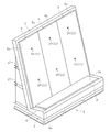
- FIG. 1 is a perspective view of a glass plate package 1 according to the first embodiment of the present invention.
- the glass plate package 1 includes a glass plate packing pallet 2 and a glass plate laminate 3 packed on the glass plate packing pallet 2.
- the glass plate laminate 3 is formed by laminating a plurality of rectangular or square glass plates G in a vertical posture through interleaf paper I.
- the interleaf paper I is disposed on the backmost side of the glass plate laminate 3.
- the weight of the glass plate laminate 3 is 200 kg to 3800 kg.
- the number of glass plates G constituting the glass plate laminate 3 is 200 to 400
- the size of the glass plate G is 1000 mm ⁇ 1200 mm to 2500 mm ⁇ 2500 mm
- the thickness of the glass plate G is 300 ⁇ m to 700 ⁇ m.
- the interleaf paper I used for the glass plate laminate 3 is, for example, pure pulp paper.
- the size of the interleaf paper I is usually larger than that of the glass plates G and is alternately arranged with the glass plates G so that the glass plates G do not directly contact each other.
- stacked alternately is comprised.
- the pallet 2 for packing glass plates mainly includes a base part 4, a back support part 5, a bottom support part 6, a holding part 7, a buffer plate 8, and a base plate 9 on the bottom side.
- the back support part 5 stands up from the base part 4 and supports the back face of the glass plate laminate 3.
- the bottom support 6 supports the bottom (lower end) of the glass plate laminate 3 on the base 4.
- the buffer plate 8 is disposed between the glass plate laminate 3 and the back support 5, and the bottom side receiving plate 9 is disposed between the glass plate laminate 3 and the bottom support 6.
- three buffer plates 8 are disposed on the front surface 5 a side of the back surface support portion 5, and a bottom side receiving plate 9 is disposed on the top surface 6 a side of the bottom surface support portion 6. It is arranged.
- the following is the same) of the buffer plate 8 is the back surface.
- the buffer plate 8 is attached to a region smaller than the width direction dimension of the front surface 5a of the support portion 5 and excluding the upper edge portion and both side edge portions of the front surface 5a.
- the area of the glass plate G of the glass plate laminated body 3 is smaller than the area of the front surface 8a of the buffer plate 8, and in the state which laminated
- the front surface 5a of the back support portion 5 is inclined backward by a predetermined angle (for example, 5 ° to 25 °) with respect to the vertical direction. Further, the front surface 5a of the back surface support portion 5 is at an angle of, for example, 90 ° to 100 ° with respect to the upper surface 6a of the bottom side support portion 6 (that is, the support surface 9a of the receiving plate 9 on the bottom side).
- the upper surface 6a of 6 (the support surface 9a of the receiving plate 9 on the bottom side) is inclined with respect to the horizontal direction of 10 ° to 25 °, for example.
- the buffer plate 8 and the base plate 9 on the bottom side can be formed of a material having a relatively high elasticity (low rigidity) such as a foamed resin.
- both the buffer plate 8 and the base plate 9 are made of foamed polypropylene as a main material.
- the back support 5 is provided with a plurality of protrusions 10 that protrude toward the buffer plate 8. Further, the buffer plate 8 is provided with a plurality of fitted portions 11 that fit into the protruding portions 10.
- the details of the protruding portion 10 and the fitted portion 11 will be described.
- the same number of protrusions 10 and fitted parts 11 are provided. Specifically, as shown in FIG. 4, the three protruding portions 10 and the fitted portions 11 are disposed above the center in the height direction of the buffer plate 8, and the height direction of the buffer plate 8. Three projecting portions 10 and a fitted portion 11 are disposed below the center.
- the upper protrusion 10 and the fitted part 11 are both arranged on the same virtual straight line X1, and the lower protruding part 10 and the fitted part 11 are both on the same virtual straight line X2. Arranged. These two virtual straight lines X1 and X2 are parallel to each other.
- the back support portion 5 is constituted by a metal frame 12 (portion indicated by a broken line in FIG. 4), and a plurality of protrusions 10 are formed on the frame 12.
- the protrusion 10 is formed on the back support 5 by joining small pieces made of a metal material similar to that of the frame 12 by welding or the like, for example.
- the protrusion 10 has a cylindrical shape as shown in FIG. 5 when viewed from the protruding direction.
- the fitted portion 11 has an annular hole shape in the present embodiment.
- the fitted part 11 is a through hole as shown in FIG. Thereby, the front end surface of the protrusion 10 is exposed (see FIG. 5).
- a value obtained by subtracting the maximum outer diameter dimension d1 of 10 is set to 0 mm or more and 20 mm or less, preferably 2 mm or more and 15 mm or less, more preferably 3 mm or more and 10 mm or less.
- the maximum outer diameter dimension of the protrusion 10 means the maximum diameter of a circle circumscribing the protrusion 10 in a state where the protrusion 10 is viewed in plan (viewed from the protrusion direction).
- the maximum inner diameter dimension here means the maximum diameter of a circle circumscribing the contour of the fitted portion 11 in a state where the fitted portion 11 is viewed in plan view.
- the maximum inner diameter d2 of the fitted portion 11 is, for example, preferably set to 5 mm or more and 50 mm or less, preferably 10 mm or more and 40 mm or less, more preferably 15 mm or more. And it is good to set to 30 mm or less.
- the protrusion height of the protrusion 10 (here, the height dimension based on the front surface 5a of the back support 5) h1 is set smaller than the thickness dimension h2 of the buffer plate 8, as shown in FIG. .
- the glass plate G can be reliably supported over the entire front surface 8a of the buffer plate 8.
- the holding unit 7 includes a belt 13, a pressing bar 14 as a pressing member, and a side stopper 15 as main elements.
- the belt 13 includes a ratchet portion 16 (a so-called ratchet belt), for example, and is hung on a hook 17 disposed behind the back support portion 5 so as to be doubled. It is fixed in a state of being tightened by the ratchet portion 16 or the like on the contact surface 14a in surface contact with the belt 13 on the surface opposite to the glass plate laminate 3.
- the front side receiving plate 18 is placed on the foremost side of the glass plate laminate 3, and the front side receiving plate 18 is further on the front side.
- a frame plate 19 is placed.
- the frame plate 19 is provided with a hook 20. With the presser bar 14 placed on the hook 20, the presser bar 14 is attached to the belt 13 together with the glass plate laminate 3, the front receiving plate 18 and the frame plate 19. Therefore, it can be pressed to the back support portion 5 side.
- the presser bar 14 is attached to the belt 13 with its longitudinal direction aligned with the width direction of the glass plate laminate 3 (disposed on the front side of the glass plate laminate 3). )
- the two pressing bars 14 are arranged along the width direction of the glass plate laminate 3.
- the protruding portion 10 and the fitted portion 11 and the pressing bar 14 are in a positional relationship shifted from each other in the vertical direction. In other words, the protruding portion 10 and the fitted portion 11 are not directly below the pressing direction of the pressing bar 14.
- one of the back support portion 5 and the buffer plate 8 adjacent to each other is provided with the protruding portion 10 protruding toward the buffer plate 8 on the back support portion 5 in the present embodiment.
- the other buffer plate 8 is provided with a fitted portion 11 that fits the protruding portion 10.
- the buffer plate 8 does not need to be fixed to the back support portion 5 by adhesion, so that the engagement state between the protruding portion 10 and the fitted portion 11 is maintained even when the temperature changes during transportation.
- the members 5 and 8 can be freely deformed without being constrained to each other. Therefore, a predetermined fixing force can be maintained between the back support part 5 and the buffer plate 8, and the buffer plate 8 can be prevented from being displaced, which can cause damage to the glass plate G during transportation. Can be prevented.
- FIG. 9 is a plan view of the protrusion 23 and the fitted portion 24 according to the second embodiment of the present invention.
- the projecting portion 23 and the fitted portion 11 according to this embodiment both have a polygonal shape (pentagonal shape in FIG. 9), and are in surface contact mainly with two sides on the upper side in the vertical direction. Is possible.
- FIG. 10 is a plan view of the protruding portion 25 and the fitted portion 26 according to the third embodiment of the present invention.
- the protrusion 25 according to the present embodiment has a substantially rectangular shape
- the fitted portion 26 has a circular shape. This configuration also ensures that the projection 25 and the mated portion 26 are fitted at a predetermined portion (for example, two corners on the upper side in the vertical direction of the projection 25) without performing dimensional control with high accuracy. It is possible to generate a corresponding frictional force in contact with the inner peripheral surface of the portion 26.
- FIG. 11 shows a cross-sectional view of the protrusion 27 and the fitted portion 28 according to the fourth embodiment of the present invention.
- the protrusion 27 according to the present embodiment has a partial conical shape with a diameter decreasing from the proximal end side toward the distal end side.
- the fitted portion 28 may have an annular shape with a constant inner diameter dimension as shown in FIG.
- the inner diameter dimension decreases (reduced diameter) as with the protruding portion 27. It is good also as a partial cone shape.
- FIG. 12 shows a cross-sectional view of the protrusion 29 and the fitted part 30 according to the fifth embodiment of the present invention.
- the protrusion 29 according to the present embodiment has a so-called key shape (hook type) in a sectional view. That is, the protrusion 29 has a shape having a maximum outer diameter dimension at the front end side in the protruding direction when viewed from the protruding direction.
- a flange 31 is formed that extends from the tip of the protrusion 29 in a direction substantially perpendicular to the protruding direction of the protrusion 29 (a direction along the front surface 5a).
- the fitted portion 30 has a bottomed hole shape formed in the surface opposite to the front surface 8 a of the buffer plate 8, and extends in a direction substantially perpendicular to the thickness direction of the buffer plate 8 from the bottom portion.
- An extending lateral hole 32 is formed.
- the protruding portion and the fitted portion may have a certain longitudinal dimension along a predetermined direction in a plan view.
- FIG. 13 has shown the figure which planarly viewed the projection part 33 and the to-be-fitted part 34 which concern on the example (6th embodiment of this invention).
- the protrusion 33 according to this embodiment has a so-called rib shape, and the fitted portion 34 has a long hole shape.
- the protrusion and the fitted portion can take any shape and combination as long as they fit each other when they are overlapped in the stacking direction of the glass sheets G.
- FIG. 14 shows a plan view of the protrusions 35a to 35c according to one example (seventh embodiment of the present invention).
- the protrusions 35a to 35c according to the present embodiment are each in the longitudinal direction (for example, the two furthest points out of the contact points between the protrusions 35a to 35c and the circumscribed circle) in a plane perpendicular to the protrusion direction.
- the shape has a direction of a straight line connecting two contact points, and the longitudinal directions are different from each other.
- the longitudinal direction of the protrusion 35a on the left side in the width direction is obliquely upper left and obliquely lower right.
- the longitudinal direction of the protrusion 35b at the center in the width direction is the direction passing vertically upward and downward, while the longitudinal direction of the protrusion 35c on the right in the width direction is obliquely upper right and obliquely lower left. It is in the direction to pass.
- the protrusions 35a to 35c having different longitudinal directions in this way, the direction in which the buffer plate 8 is obliquely shifted to the upper left, that is, the engagement state between one protrusion 35a and the fitted part 36 is eliminated. Even when the force of the direction is received, the engagement state between the other protrusions 35b and 35c and the fitted portion 36 is maintained. Therefore, it is possible to expect an effect that the buffer plate 8 is difficult to be detached from the back surface support portion 5 even in response to an unexpected impact or the like.
- FIG. 15 is a diagram showing an arrangement mode of the protrusion 10 and the fitted portion 11 according to an example (eighth embodiment of the present invention).
- the other protrusion (the center in the width direction) 10 and the fitted part 11 are disposed at a position deviating from the virtual straight line X2 while being disposed on X2.
- the shock absorbing board 8 It can be expected to exhibit an excellent resistance to deformation.
- FIG. 16 is a view for explaining the positional relationship between the buffer plate 8 and the bottom support portion 6 according to the ninth embodiment of the present invention.
- the buffer plate 8 has a lower end and a bottom support. It is supported by the back surface support part 5 in a state where a predetermined gap g is provided between the top surface 6a of the part 6.
- the buffer plate 8 is always suspended from the back support portion 5, even if there is some variation in the shape accuracy or position accuracy of the protrusion 10 and the fitted portion 11, The protruding portion 10 and the fitted portion 11 are securely engaged on the upper side. Therefore, it is possible to stably support the buffer plate 8 on the back support portion 5.
- the protrusion 10 is provided on the back support portion 5 and the fitted portion 11 is provided on the buffer plate 8 is illustrated.
- the fit portion 11 is provided on the back support portion 5 and the buffer plate. 8 may be provided with a protrusion 10.
- at least one protruding portion 10 and two or more fitted portions 11 are provided on the back support portion 5, and two or more protruding portions 10 and at least one fitted portion 11 are provided on the buffer plate 8. May be.
Landscapes
- Engineering & Computer Science (AREA)
- Mechanical Engineering (AREA)
- Packaging Frangible Articles (AREA)
- Pallets (AREA)
Abstract
本発明に係るガラス板梱包用パレット2は、複数のガラス板Gを縦姿勢で積層してなるガラス板積層体3の底辺を支持する底辺支持部6と、ガラス板積層体3の背面と当接する緩衝板8と、緩衝板8を介してガラス板積層体3の背面を支持する背面支持部5とを備える。背面支持部5と緩衝板8との何れか一方に、他方に向けて突出する突起部10が設けられると共に、他方に、突起部10と嵌り合う被嵌合部11が設けられている。
Description
本発明は、ガラス板梱包用パレット及びガラス板梱包体に関する。
近年、フラットパネルディスプレイ用ガラス基板の大型化及び薄肉化に伴い、ガラス基板の梱包に際しては、ガラス基板を縦姿勢で積層した状態で行うことが主流となっている。また、ガラス基板を縦姿勢で積層した状態で梱包するためのパレットとしては、複数のガラス基板を縦姿勢で積層してなるガラス基板積層体の底辺を支持する底辺支持部と、ガラス基板積層体の背面を支持する背面支持部と、背面支持部とガラス基板積層体との間に配設される緩衝板(背板とも呼ばれる。)とを備えたものが公知である(例えば、特許文献1を参照)。
ところで、特許文献1の如く緩衝板を備えたパレットを用いてガラス基板積層体を梱包し、梱包体を輸送する場合、輸送中にガラス基板が破損することがある。このようなガラス基板の破損の原因の一つとして、輸送時における緩衝板の位置ずれが考えられる。
また、ガラス基板が破損した場合、開梱時に緩衝板の上側が前面側に倒れ込んでくるといった事態が発生していた。緩衝板が倒れ込むことによって、破損したガラス基板の処理が困難になり、あるいは破損していないガラス基板の取出しが困難になるといった問題が生じていた。
以上の理由より、緩衝板は背面支持部に対して強固に固定されていることが望ましい。ここで、緩衝板は、通常、接着により背面支持部に固定されている。また、特許文献1には、材質の違いに起因した接着面の剥離を防止するための技術として、緩衝板の側に熱変形を吸収するための溝を設けることが記載されている。
しかしながら、接着によって緩衝板を背面支持部に確実に固定することは困難であった。接着剤を用いた固定手段は、材質の異なる部材同士の固定には適さない場合があるためである。すなわち、背面支持部は、通常、ガラス基板梱包用パレットのフレーム部材で構成されることになるため金属製であるのに対し、緩衝板は、ガラス基板積層体への衝撃吸収を図る目的から、発泡樹脂など比較的弾力性に富む(剛性の低い)材質で形成されることが多い。そのため、背面支持部と緩衝板とでは、輸送中の温度変化に伴う熱変形の差がどうしても大きくなる傾向にある。これでは、たとえ特許文献1に記載のように熱変形を吸収するための構造(溝)を設けたとしても、接着面の剥離を十分に防ぐことは難しい。
以上の事情に鑑み、本明細書では、緩衝板が背面支持部からずれることにより生じるガラス板の破損を防止して、長期間にわたって安全にガラス板積層体を輸送することのできるガラス板梱包用パレットを提供することを、本発明により解決すべき技術的課題とする。
前記技術的課題の解決は、本発明に係るガラス板梱包用パレットにより達成される。すなわち、このパレットは、複数のガラス板を縦姿勢で積層してなるガラス板積層体の底辺を支持する底辺支持部と、ガラス板積層体の背面と当接する緩衝板と、緩衝板を介してガラス板積層体の背面を支持する背面支持部とを備えたガラス板梱包用パレットにおいて、背面支持部と緩衝板との何れか一方に、他方に向けて突出する突起部が設けられると共に、他方に、突起部と嵌り合う被嵌合部が設けられている点をもって特徴付けられる。
このように、本発明に係るパレットでは、背面支持部と緩衝板の一方に、他方に向けて突出する突起部を設けると共に、他方に突起部と嵌り合う被嵌合部を設けた。背面支持部及び緩衝板はともに、縦姿勢で積層してなるガラス板積層体の背面を支持するものであるから、緩衝板の自重により突起部と被嵌合部とがその鉛直方向上側又は下側で係合した状態となる。これにより突起部と被嵌合部との間に十分な大きさの摩擦力を発生させて、緩衝板と背面支持部とを相互に固定することができる。このような固定形態をとるのであれば、緩衝板を背面支持部に接着で固定する必要はないため、輸送時の温度変化に際しても、突起部と被嵌合部との係合状態を維持しながら、各々の部材が互いに拘束されることなく自由に熱変形を生じさせることができる。従って、所定の固定力を保つことができ、問題となるような緩衝板のずれを防止して、輸送時におけるガラス板の破損を可及的に防止することが可能となる。
また、本発明に係るガラス板梱包用パレットは、背面支持部に突起部が設けられると共に、緩衝板に被嵌合部が設けられており、突起部の突出高さが緩衝板の厚み寸法以下であるものであってもよい。
このように突起部の突出高さを設定することにより、たとえ被嵌合部が貫通穴であったとしても、突起部が緩衝板の前面(ガラス板積層体と当接する側の表面)から飛び出る事態を確実に防止することができる。よって、ガラス板の積層状態が安定する。
また、本発明に係るガラス板梱包用パレットは、少なくとも一組の突起部と被嵌合部が、緩衝板の高さ方向中央よりも上方に配設されているものであってもよい。
このように構成することで、緩衝板の高さ方向上側を背面支持部に固定することができる。よって、既述のようにガラス板が万が一破損して緩衝板がその上側から倒れ込もうとした場合であっても、緩衝板の高さ方向上側に配置した少なくとも一組の突起部と被嵌合部とにより、高さ方向上側における緩衝板の保持力を高めて緩衝板が前方に倒れ込む事態を防止できる。
また、本発明に係るガラス板梱包用パレットは、被嵌合部が貫通穴であるものであってもよい。
被嵌合部を貫通穴とすれば、被嵌合部の貫通方向全域を突起部との係合に用いることができるので、緩衝板と背面支持部との固定力向上を図ることが可能となる。また、貫通穴であれば、被嵌合部の加工も非常に容易となる。
また、本発明に係るガラス板梱包用パレットは、被嵌合部が穴形状をなすもので、その最大内径寸法が、5mm以上でかつ50mm以下に設定されているものであってもよい。
このように被嵌合部が穴形状をなす場合、その最大内径寸法を設定することで、被嵌合部が設けられている部材(緩衝板又は背面支持部)自体の強度を確保しながら、緩衝板を確実に背面支持部に固定することが可能となる。すなわち、被嵌合部の最大内径寸法が50mm以下であれば、被嵌合部を設けた部材の強度が著しく損なわれ、当該部材が変形し易くなるおそれがない。一方、被嵌合部の最大内径寸法が5mm以上であれば、突起部との間で十分な摩擦力が得られず、緩衝板と背面支持部との固定力が不足するおそれがない。従って、上述の効果を享受することが可能となる。
また、本発明に係るガラス板梱包用パレットは、突起部をその突出方向から見た場合の最大外径寸法と、被嵌合部の最大内径寸法との差が、0mm以上でかつ20mm以下に設定されているものであってもよい。
このように突起部の最大外径寸法と被嵌合部の最大内径寸法を設定することにより、突起部と被嵌合部とが隙間なく又は若干の隙間を介して嵌り合うことになるので、容易かつ確実に突起部を被嵌合部に嵌め合わせることができる。
また、本発明に係るガラス板梱包用パレットは、複数の突起部がそれぞれ、突出方向に対し垂直な面内において長手方向を有する形状をなし、複数の突起部のうち、少なくとも一つの突起部の長手方向と、他の突起部の長手方向とが互いに異なるものであってもよい。
このように突起部によって最大外径寸法の向きを異ならせることで、仮に緩衝板が所定の方向にずれる向き、すなわち一部の突起部と被嵌合部との係合状態が解消される向きの力を受けた場合であっても、残部の突起部と被嵌合部との係合状態は維持される。よって、不意の衝撃等に対しても緩衝板が背面支持部から外れ難くなる効果が期待できる。
また、本発明に係るガラス板梱包用パレットは、複数の突起部のうち三つ以上の突起部が、同一の仮想直線上に配設されているものであってもよい。
このように複数の突起部のうち三つ以上の突起部が同一の仮想直線上に配列されていれば、その配列方向(仮想直線の向き)によって、緩衝板が背面支持部から外れる向きの傾動に対して非常に高い抵抗力を発揮することが可能となる。例えば三つ以上の突起部がガラス板積層体の幅方向に沿って一直線上に配列される場合、これら一直線上に並ぶ全ての突起部が、緩衝板の幅方向に沿った軸線まわりの傾動に対する抵抗(被嵌合部との摩擦力)として有効に作用する。従って、緩衝板の傾動に対しても非常に高い抵抗力を発揮する効果が期待できる。
あるいは、本発明に係るガラス板梱包用パレットは、複数の突起部のうち、二つ以上の突起部が、同一の仮想直線上に配設されると共に、他の一つ又は二つ以上の突起部が、仮想直線上から外れた位置に配設されているものであってもよい。
このように複数の突起部を配置した場合には、三つ以上の突起部を同一の仮想直線上に配設した場合と比べて緩衝板の変形に対して優れた抵抗力を発揮する効果が期待できる。
また、本発明に係るガラス板梱包用パレットは、緩衝板の下端と、底辺支持部との間に所定の隙間を設けた状態で、背面支持部に支持されているものであってもよい。
このように構成すれば、緩衝板が背面支持部に吊り下げられた状態となるため、突起部と被嵌合部の加工精度のばらつきが多少あったとしても、突起部と被嵌合部とがその上側(突起部が背面支持部に設けられた場合)又は下側(突起部が緩衝板に設けられた場合)で確実に係合する。よって、緩衝板を背面支持部に安定的に固定することが可能となる。
また、以上の説明に係るガラス板梱包用パレットは、接着によることなく緩衝板を背面支持部に固定することで、温度変化に伴う熱変形を許容して、背面支持部に対する緩衝板のずれを抑制可能とするものであるから、例えばこのガラス板梱包用パレットと、ガラス板梱包用パレットに載置されたガラス板積層体とを備えたガラス板梱包体として好適に提供することが可能となる。
以上に述べたように、本発明に係るガラス板梱包用パレットによれば、緩衝板が背面支持部からずれることにより生じるガラス板の破損を防止して、長期間にわたって安全にガラス板積層体を輸送することが可能となる。
<本発明の第一実施形態>
以下、本発明の第一実施形態を、図1~図8を参照して説明する。なお、本実施形態では、梱包対象となるガラス板をフラットパネルディスプレイ用ガラス基板とし、このガラス基板が合紙を介して積層された状態のガラス基板梱包体を梱包する場合を例にとって説明する。
以下、本発明の第一実施形態を、図1~図8を参照して説明する。なお、本実施形態では、梱包対象となるガラス板をフラットパネルディスプレイ用ガラス基板とし、このガラス基板が合紙を介して積層された状態のガラス基板梱包体を梱包する場合を例にとって説明する。
図1は、本発明の第一実施形態に係るガラス板梱包体1の斜視図である。このガラス板梱包体1は、ガラス板梱包用パレット2と、ガラス板梱包用パレット2の上で梱包されるガラス板積層体3とを備える。
ガラス板積層体3は、複数枚の矩形状ないし正方形状のガラス板Gが縦姿勢で合紙Iを介して積層されたものである。本実施形態では、ガラス板積層体3の最も背面側には合紙Iが配置されている。
ここで、ガラス板積層体3に関する諸元の一例について述べると、ガラス板積層体3の重量は、200kg~3800kgである。また、この際、ガラス板積層体3を構成するガラス板Gの枚数は200枚~400枚、ガラス板Gの大きさは1000mm×1200mm~2200mm×2500mm、ガラス板Gの厚さは300μm~700μmである。ガラス板積層体3に使用される合紙Iは、例えば純パルプ紙である。合紙Iの大きさは、通常、ガラス板Gより大きく、ガラス板G同士が直接接触しないようにガラス板Gと交互に配置される。これにより、ガラス板Gと合紙Iとが交互に積層されてなるガラス板積層体3が構成される。
ガラス板梱包用パレット2は、基台部4と、背面支持部5と、底辺支持部6と、保持部7と、緩衝板8、及び底辺側の受け板9とを主に備える。背面支持部5は、基台部4から起立してガラス板積層体3の背面を支持する。底辺支持部6は、基台部4上でガラス板積層体3の底辺(下端)を支持する。緩衝板8は、ガラス板積層体3と背面支持部5との間に配設され、底辺側の受け板9は、ガラス板積層体3と底辺支持部6との間に配設される。本実施形態では、図2に示すように、三個の緩衝板8が背面支持部5の前面5a側に配設されると共に、底辺側の受け板9が底辺支持部6の上面6a側に配設されている。
また、本実施形態では、図2に示すように、緩衝板8の幅方向寸法(ここでいう幅方向とはガラス板Gの幅方向と同じである。以下、同じ。)の合計は、背面支持部5の前面5aの幅方向寸法よりも小さく、前面5aの上方縁部と両側方縁部を除いた領域に緩衝板8が取り付けられた状態となっている。この際、ガラス板積層体3のガラス板Gの面積は、緩衝板8の前面8aの面積より小さく、図1に示すようにガラス板Gを積層した状態では、緩衝板8の周縁部がガラス板G(ガラス板積層体3)から食み出た状態となっている。従って、ガラス板Gはその全面を(合紙Iを介して)緩衝板8の前面8aで支持された状態となっている。
また、背面支持部5の前面5aは、図3に示すように、鉛直方向に対して所定角度(例えば5°~25°)後方に傾斜している。また、背面支持部5の前面5aは、底辺支持部6の上面6a(すなわち底辺側の受け板9の支持面9a)に対して例えば90°~100°の角度をなしており、底辺支持部6の上面6a(底辺側の受け板9の支持面9a)は、例えば10°~25°水平方向に対して傾斜している。
なお、緩衝板8と底辺側の受け板9は、例えば発泡樹脂など比較的弾力性に富む(剛性の低い)材質で形成することが可能である。具体例を一つ挙げると、緩衝板8と底辺側の受け板9はともに発泡ポリプロピレンを主たる材質として形成される。
背面支持部5には、図3及び図4に示すように、緩衝板8に向けて突出する複数の突起部10が設けられる。また、緩衝板8には、突起部10と嵌り合う複数の被嵌合部11が設けられる。以下、突起部10と被嵌合部11の詳細を説明する。
本実施形態では、突起部10と被嵌合部11とは同じ数だけ配設されている。具体的には、図4に示すように、緩衝板8の高さ方向中央よりも上側に3個の突起部10と被嵌合部11が配設されると共に、緩衝板8の高さ方向中央よりも下側に3個の突起部10と被嵌合部11が配設される。これら上側の突起部10と被嵌合部11は何れも、同一の仮想直線X1上に配設され、下側の突起部10と被嵌合部11は何れも、同一の仮想直線X2上に配設される。これら二本の仮想直線X1,X2は互いに平行である。また、共通の仮想直線X1,X2上にある各三個の突起部10並びに被嵌合部11の幅方向間隔は同じである。さらに、本実施形態では、背面支持部5は金属製のフレーム12(図4中、破線で示す部分)で構成され、このフレーム12上に複数の突起部10が形成されている。突起部10は、例えば、フレーム12と同様の金属材質からなる小片部材を溶接等により接合することで背面支持部5に形成されている。
突起部10は、本実施形態では、その突出方向から見た場合、図5に示すように円柱状をなす。また、被嵌合部11は、本実施形態では円環穴形状をなす。さらにいえば、被嵌合部11は、図6に示すように貫通穴である。これにより突起部10の先端面が露出した状態となっている(図5を参照)。本実施形態のように、突起部10が背面支持部5に設けられていると共に、被嵌合部11が緩衝板8に設けられている場合、突起部10と被嵌合部11とは、鉛直方向上側(図5でいえば上側)で互いに当接する。
また、図5に示すように、突起部10の最大外径寸法d1と被嵌合部11の最大内径寸法d2との差、実際には、被嵌合部11の最大内径寸法d2から突起部10の最大外径寸法d1を減じた値は、0mm以上でかつ20mm以下に設定され、好ましくは2mm以上でかつ15mm以下に設定され、より好ましくは3mm以上でかつ10mm以下に設定される。特に、突起部10と被嵌合部11が複数ある場合に寸法差d2-d1が小さ過ぎると、特定の突起部10と被嵌合部11の組合わせについて嵌め合わせることができても、他の組合わせについて突起部10と被嵌合部11との位置が合致せず嵌め合わせることができなくなるおそれがある。そのため、上述のようにある程度の寸法差d2-d1をもたせることで、複数の突起部10同士および被嵌合部11同士の位置精度をそれほど高めなくても確実に全ての突起部10を被嵌合部11に嵌め合わせることが可能となる。なお、ここでいう突起部10の最大外径寸法とは、突起部10を平面視した(突出方向から見た)状態において、突起部10と外接する円の最大直径を意味するものとする。また、ここでいう最大内径寸法とは、被嵌合部11を平面視した状態において、被嵌合部11の輪郭と外接する円の最大直径を意味するものとする。
また、被嵌合部11の最大内径寸法d2は、例えば5mm以上でかつ50mm以下に設定されるのがよく、好ましくは10mm以上でかつ40mm以下に設定されるのがよく、より好ましくは15mm以上でかつ30mm以下に設定されるのがよい。このように設定することで、被嵌合部11が設けられている部材である緩衝板8自体の強度を確保しながら、緩衝板8を確実に背面支持部5に固定することが可能となる。
また、突起部10の突出高さ(ここでは背面支持部5の前面5aを基準とした高さ寸法)h1は、図6に示すように、緩衝板8の厚み寸法h2よりも小さく設定される。これによりガラス板Gを確実に緩衝板8の前面8aの全域で支持することが可能となる。
保持部7は、本実施形態では、図1に示すように、ベルト13と、押さえ部材としての押さえバー14並びにサイドストッパ15とを主たる要素として構成される。このうちベルト13は、例えばラチェット部16を備えたもの(いわゆるラチェットベルト)で、背面支持部5の後方に配設されるフック17に掛けて、二重にした状態で、押さえバー14の前面(ガラス板積層体3と背反する側の表面で、ベルト13と面接触する接触面14a)上でラチェット部16等により締め付けた状態で固定される。また、この際、ガラス板積層体3の最も前面側には、図1及び図7に示すように、前面側の受け板18が載置され、前面側の受け板18のさらに前面側にはフレーム板19が載置されている。フレーム板19にはフック20が設けられており、このフック20に押さえバー14を載せた状態で、押さえバー14を、ガラス板積層体3と前面側の受け板18及びフレーム板19と共にベルト13で背面支持部5側に押圧可能としている。
このうち、押さえバー14は、図8に示すように、その長手方向をガラス板積層体3の幅方向に合わせた状態でベルト13に取り付けられる(ガラス板積層体3の前面側に配設される)。本実施形態では、二本の押さえバー14がガラス板積層体3の幅方向に沿って配設されている。また、この際、突起部10並びに被嵌合部11と、押さえバー14とは鉛直方向で互いにずれた位置関係にある。言い換えると、突起部10並びに被嵌合部11は、押さえバー14の押圧方向直下にはない。
このように、本発明に係るパレット2では、互いに隣り合う背面支持部5と緩衝板8の一方、本実施形態では背面支持部5に、緩衝板8に向けて突出する突起部10を設けると共に、他方となる緩衝板8に、突起部10と嵌り合う被嵌合部11を設けた。これにより、突起部10と被嵌合部11とが緩衝板8の自重によりその鉛直方向上側で係合した状態となる(図5及び図6を参照)。よって突起部10と被嵌合部11との間に十分な大きさの摩擦力を発生させて、緩衝板8と背面支持部5とを相互に固定することができる。このように固定すれば、緩衝板8を背面支持部5に接着で固定する必要はないため、輸送時の温度変化に際しても、突起部10と被嵌合部11との係合状態を維持しながら、各々の部材5,8が互いに拘束されることなく自由に熱変形を生じさせることができる。従って、背面支持部5と緩衝板8との間で所定の固定力を保つことができ、問題となるような緩衝板8のずれを防止して、輸送時におけるガラス板Gの破損を可及的に防止することが可能となる。
以上、本発明に係るガラス板梱包用パレット並びにガラス板梱包体の第一実施形態を説明したが、このパレット並びに梱包体は、当然に本発明の範囲内において任意の形態を採ることができる。
<本発明の第二実施形態>
例えば突起部10と被嵌合部11の形状について、第一実施形態ではともに円形状としたが、もちろんこれ以外の形状とすることも可能である。図9は、本発明の第二実施形態に係る突起部23と被嵌合部24を平面視した図である。この図に示すように、本実施形態に係る突起部23と被嵌合部11はともに多角形状(図9では五角形状)をなすもので、鉛直方向上側の主に二辺で面接触することが可能となっている。この構成によれば、突起部23と被嵌合部24の寸法管理(加工精度など)をそれほど高精度に行わなくても、確実に所定の面積で接触させて相応の摩擦力を発生させることが可能となる。
例えば突起部10と被嵌合部11の形状について、第一実施形態ではともに円形状としたが、もちろんこれ以外の形状とすることも可能である。図9は、本発明の第二実施形態に係る突起部23と被嵌合部24を平面視した図である。この図に示すように、本実施形態に係る突起部23と被嵌合部11はともに多角形状(図9では五角形状)をなすもので、鉛直方向上側の主に二辺で面接触することが可能となっている。この構成によれば、突起部23と被嵌合部24の寸法管理(加工精度など)をそれほど高精度に行わなくても、確実に所定の面積で接触させて相応の摩擦力を発生させることが可能となる。
<本発明の第三実施形態>
また、以上の実施形態では突起部10,23と被嵌合部11,24とが互いに相似形状である場合を例示したが、もちろん互いに非相似となるように形成することも可能である。図10は、本発明の第三実施形態に係る突起部25と被嵌合部26を平面視した図である。この図に示すように、本実施形態に係る突起部25は略矩形状をなすのに対し、被嵌合部26は円形状をなしている。この構成によっても、突起部25と被嵌合部26の寸法管理をそれほど高精度に行わなくても確実に所定の部位(例えば突起部25の鉛直方向上側の二つの角部)で被嵌合部26の内周面と接触させて相応の摩擦力を発生させることが可能となる。
また、以上の実施形態では突起部10,23と被嵌合部11,24とが互いに相似形状である場合を例示したが、もちろん互いに非相似となるように形成することも可能である。図10は、本発明の第三実施形態に係る突起部25と被嵌合部26を平面視した図である。この図に示すように、本実施形態に係る突起部25は略矩形状をなすのに対し、被嵌合部26は円形状をなしている。この構成によっても、突起部25と被嵌合部26の寸法管理をそれほど高精度に行わなくても確実に所定の部位(例えば突起部25の鉛直方向上側の二つの角部)で被嵌合部26の内周面と接触させて相応の摩擦力を発生させることが可能となる。
<本発明の第四実施形態>
また、以上の実施形態では、突起部10,23,25と被嵌合部11,24,26が何れもガラス板Gの積層方向で平面視形状が一定である場合を例示したが(図6等を参照)、もちろん、これ以外の形態をとることも可能である。図11は、本発明の第四実施形態に係る突起部27と被嵌合部28の断面図を示している。この図に示すように、本実施形態に係る突起部27は、その基端側から先端側に向かうにつれて縮径する部分円錐形状をなしている。この場合、被嵌合部28は、図11に示すように内径寸法が一定の円環形状としてもよく、あるいは図示は省略するが、突起部27と同様、内径寸法が減少する(縮径)する部分円錐形状としてもよい。このように構成することで、緩衝板8の背面支持部5への重ね合せ時、被嵌合部28が突起部27の外周面27aが被嵌合部28と当接することで被嵌合部28を適正な位置に案内する作用が期待できる。従って、容易に緩衝板8を背面支持部5上に取り付けることが可能となる。
また、以上の実施形態では、突起部10,23,25と被嵌合部11,24,26が何れもガラス板Gの積層方向で平面視形状が一定である場合を例示したが(図6等を参照)、もちろん、これ以外の形態をとることも可能である。図11は、本発明の第四実施形態に係る突起部27と被嵌合部28の断面図を示している。この図に示すように、本実施形態に係る突起部27は、その基端側から先端側に向かうにつれて縮径する部分円錐形状をなしている。この場合、被嵌合部28は、図11に示すように内径寸法が一定の円環形状としてもよく、あるいは図示は省略するが、突起部27と同様、内径寸法が減少する(縮径)する部分円錐形状としてもよい。このように構成することで、緩衝板8の背面支持部5への重ね合せ時、被嵌合部28が突起部27の外周面27aが被嵌合部28と当接することで被嵌合部28を適正な位置に案内する作用が期待できる。従って、容易に緩衝板8を背面支持部5上に取り付けることが可能となる。
<本発明の第五実施形態>
図12は、本発明の第五実施形態に係る突起部29と被嵌合部30の断面図を示している。この図に示すように、本実施形態に係る突起部29は、断面視でいわゆるカギ型(フック型)形状をなしている。すなわち、突起部29は、その突出方向から見た場合にその突出方向先端側で最大外径寸法となる形状をとっている。具体的には、突起部29の先端から突起部29の突出方向と略直交する向き(前面5aに沿った方向)に伸びる鍔部31が形成されている。また、被嵌合部30は、緩衝板8の前面8aとは反対側の表面に開口形成された有底穴形状をなすもので、その底部から緩衝板8の厚み方向と略直交する向きに伸びる横穴部32が形成されている。これにより、緩衝板8を背面支持部5上に配置して、突起部29を被嵌合部30に嵌め合せた状態から、緩衝板8を背面支持部5の前面5a上で斜め下方にスライドさせることで、鍔部31と横穴部32とが係合し、相互に固定される。このように固定されることで、緩衝板8の前面8a側への倒れ込み(突起部29からの被嵌合部30の抜け)を確実に防止できる。
図12は、本発明の第五実施形態に係る突起部29と被嵌合部30の断面図を示している。この図に示すように、本実施形態に係る突起部29は、断面視でいわゆるカギ型(フック型)形状をなしている。すなわち、突起部29は、その突出方向から見た場合にその突出方向先端側で最大外径寸法となる形状をとっている。具体的には、突起部29の先端から突起部29の突出方向と略直交する向き(前面5aに沿った方向)に伸びる鍔部31が形成されている。また、被嵌合部30は、緩衝板8の前面8aとは反対側の表面に開口形成された有底穴形状をなすもので、その底部から緩衝板8の厚み方向と略直交する向きに伸びる横穴部32が形成されている。これにより、緩衝板8を背面支持部5上に配置して、突起部29を被嵌合部30に嵌め合せた状態から、緩衝板8を背面支持部5の前面5a上で斜め下方にスライドさせることで、鍔部31と横穴部32とが係合し、相互に固定される。このように固定されることで、緩衝板8の前面8a側への倒れ込み(突起部29からの被嵌合部30の抜け)を確実に防止できる。
<本発明の第六実施形態>
また、突起部や被嵌合部は、平面視した状態で所定の方向にそって一定の長手方向寸法を有するものであってもよい。図13は、その一例(本発明の第六実施形態)に係る突起部33と被嵌合部34を平面視した図を示している。この図に示すように、本実施形態に係る突起部33はいわゆるリブ形状をなすと共に、被嵌合部34は長穴形状をなしている。このようにすることで、突起部33と被嵌合部34とをその長手方向の広範囲にわたって面接触させることができるので、さらなる固定力の向上が期待できる。
また、突起部や被嵌合部は、平面視した状態で所定の方向にそって一定の長手方向寸法を有するものであってもよい。図13は、その一例(本発明の第六実施形態)に係る突起部33と被嵌合部34を平面視した図を示している。この図に示すように、本実施形態に係る突起部33はいわゆるリブ形状をなすと共に、被嵌合部34は長穴形状をなしている。このようにすることで、突起部33と被嵌合部34とをその長手方向の広範囲にわたって面接触させることができるので、さらなる固定力の向上が期待できる。
以上のように、突起部と被嵌合部は、ガラス板Gの積層方向に重ね合わせた際に、互いに嵌り合う限りにおいて、任意の形状及び組み合わせをとることが可能である。
<本発明の第七実施形態>
また、複数の突起部10がある場合、すべての突起部10が同じ形状ないし姿勢である必要はない。図14は、その一例(本発明の第七実施形態)に係る突起部35a~35cを平面視した図を示している。この図に示すように、本実施形態に係る突起部35a~35cはそれぞれ、その突出方向に対し垂直な面内において長手方向(例えば突起部35a~35cと外接円との接点のうち最も遠い二つの接点を結ぶ直線の向き)を有する形状をなし、かつ長手方向を互いに異ならせている。具体的には、緩衝板8の幅方向に沿って配設される三個の突起部35a,35b,35cのうち、幅方向左側の突起部35aの長手方向が斜め左上と斜め右下とを通過する向きであるのに対し、幅方向中央の突起部35bの長手方向は鉛直上方と下方とを通過する向きであり、幅方向右側の突起部35cの長手方向は斜め右上と斜め左下とを通過する向きとなっている。このように長手方向が互いに異なる突起部35a~35cを設けることで、仮に緩衝板8が斜め左上にずれる向き、すなわち一つの突起部35aと被嵌合部36との係合状態が解消される向きの力を受けた場合であっても、他の突起部35b,35cと被嵌合部36との係合状態は維持される。よって、不意の衝撃等に対しても緩衝板8が背面支持部5から外れ難くなる効果が期待できる。
また、複数の突起部10がある場合、すべての突起部10が同じ形状ないし姿勢である必要はない。図14は、その一例(本発明の第七実施形態)に係る突起部35a~35cを平面視した図を示している。この図に示すように、本実施形態に係る突起部35a~35cはそれぞれ、その突出方向に対し垂直な面内において長手方向(例えば突起部35a~35cと外接円との接点のうち最も遠い二つの接点を結ぶ直線の向き)を有する形状をなし、かつ長手方向を互いに異ならせている。具体的には、緩衝板8の幅方向に沿って配設される三個の突起部35a,35b,35cのうち、幅方向左側の突起部35aの長手方向が斜め左上と斜め右下とを通過する向きであるのに対し、幅方向中央の突起部35bの長手方向は鉛直上方と下方とを通過する向きであり、幅方向右側の突起部35cの長手方向は斜め右上と斜め左下とを通過する向きとなっている。このように長手方向が互いに異なる突起部35a~35cを設けることで、仮に緩衝板8が斜め左上にずれる向き、すなわち一つの突起部35aと被嵌合部36との係合状態が解消される向きの力を受けた場合であっても、他の突起部35b,35cと被嵌合部36との係合状態は維持される。よって、不意の衝撃等に対しても緩衝板8が背面支持部5から外れ難くなる効果が期待できる。
<本発明の第八実施形態>
また、以上の実施形態では、緩衝板8の幅方向に沿って配設される3つ以上の突起部10が同一の仮想直線X1上にある場合を例示したが(図4等を参照)、もちろんこれ以外の配置態様をとることも可能である。図15は、その一例(本発明の第八実施形態)に係る突起部10及び被嵌合部11の配置態様を示す図である。この図に示すように、本実施形態に係る複数の突起部10及び被嵌合部11のうち、まず緩衝板8の鉛直方向上側に位置する三つの突起部10並びに被嵌合部11について、二つ(幅方向左側及び中央)の突起部10並びに被嵌合部11が同一の仮想直線X1上に配設される一方で、他の一つ(幅方向右側)の突起部10並びに被嵌合部11は上記仮想直線X1上から外れた位置に配設されている。また、緩衝板8の鉛直方向下側に位置する三つの突起部10並びに被嵌合部11について、二つ(幅方向左側及び右側)の突起部10並びに被嵌合部11が同一の仮想直線X2上に配設される一方で、他の一つ(幅方向中央)の突起部10並びに被嵌合部11は上記仮想直線X2上から外れた位置に配設されている。このように突起部10並びに被嵌合部11を配置した場合には、全ての突起部10を同一の仮想直線X1,X2上に配設した場合(図4等)と比べて、緩衝板8の変形に対して優れた抵抗力を発揮する効果が期待できる。
また、以上の実施形態では、緩衝板8の幅方向に沿って配設される3つ以上の突起部10が同一の仮想直線X1上にある場合を例示したが(図4等を参照)、もちろんこれ以外の配置態様をとることも可能である。図15は、その一例(本発明の第八実施形態)に係る突起部10及び被嵌合部11の配置態様を示す図である。この図に示すように、本実施形態に係る複数の突起部10及び被嵌合部11のうち、まず緩衝板8の鉛直方向上側に位置する三つの突起部10並びに被嵌合部11について、二つ(幅方向左側及び中央)の突起部10並びに被嵌合部11が同一の仮想直線X1上に配設される一方で、他の一つ(幅方向右側)の突起部10並びに被嵌合部11は上記仮想直線X1上から外れた位置に配設されている。また、緩衝板8の鉛直方向下側に位置する三つの突起部10並びに被嵌合部11について、二つ(幅方向左側及び右側)の突起部10並びに被嵌合部11が同一の仮想直線X2上に配設される一方で、他の一つ(幅方向中央)の突起部10並びに被嵌合部11は上記仮想直線X2上から外れた位置に配設されている。このように突起部10並びに被嵌合部11を配置した場合には、全ての突起部10を同一の仮想直線X1,X2上に配設した場合(図4等)と比べて、緩衝板8の変形に対して優れた抵抗力を発揮する効果が期待できる。
<本発明の第九実施形態>
また、以上の実施形態では、緩衝板8が底辺支持部6の上面6aと当接した状態で背面支持部5に固定される場合(図3等を参照)を例示したが、もちろんこれ以外の形態をとることも可能である。図16は、本発明の第九実施形態に係る緩衝板8と底辺支持部6との位置関係を説明するための図で、同図に示すように、緩衝板8は、その下端と底辺支持部6の上面6aとの間に所定の隙間gを設けた状態で背面支持部5に支持されている。このように構成すれば、緩衝板8が背面支持部5に常に吊り下げられた状態となるため、突起部10と被嵌合部11の形状精度ないし位置精度のばらつきが多少あったとしても、突起部10と被嵌合部11とがその上側で確実に係合する。よって、緩衝板8を背面支持部5に安定的に支持することが可能となる。
また、以上の実施形態では、緩衝板8が底辺支持部6の上面6aと当接した状態で背面支持部5に固定される場合(図3等を参照)を例示したが、もちろんこれ以外の形態をとることも可能である。図16は、本発明の第九実施形態に係る緩衝板8と底辺支持部6との位置関係を説明するための図で、同図に示すように、緩衝板8は、その下端と底辺支持部6の上面6aとの間に所定の隙間gを設けた状態で背面支持部5に支持されている。このように構成すれば、緩衝板8が背面支持部5に常に吊り下げられた状態となるため、突起部10と被嵌合部11の形状精度ないし位置精度のばらつきが多少あったとしても、突起部10と被嵌合部11とがその上側で確実に係合する。よって、緩衝板8を背面支持部5に安定的に支持することが可能となる。
以上、突起部と被嵌合部、並びに緩衝板と背面支持部のとり得る構成について説明したが、もちろんこれら以外の要素についても任意に構成が可能である。すなわち、底辺支持部と、背面支持部と、緩衝板とを備えたガラス板梱包用パレットにおいて、背面支持部と緩衝板の一方に、他方に向けて突出する突起部が設けられると共に、他方に、突起部と嵌り合う被嵌合部が設けられる限りにおいて、その他の構成は任意であり、上述した説明に係る事項並びに図示された事項には限定されないことはもちろんである。例えば以上の説明では、背面支持部5に突起部10を設け、緩衝板8に被嵌合部11を設けた場合を例示したが、背面支持部5に被嵌合部11を設け、緩衝板8に突起部10を設けるようにしてもよい。あるいは、少なくとも一つの突起部10と、二以上の被嵌合部11を背面支持部5に設け、二以上の突起部10と、少なくとも一つの被嵌合部11を緩衝板8に設けるようにしてもよい。
また、以上の説明では、ガラス板Gの間に合紙Iを介して積層する場合を例示したが(図1等)、もちろん合紙Iを省略してガラス板Gのみを積層する場合にも本発明に係るガラス板梱包用パレットを適用することは可能である。
Claims (11)
- 複数のガラス板を縦姿勢で積層してなるガラス板積層体の底辺を支持する底辺支持部と、
前記ガラス板積層体の背面と当接する緩衝板と、
前記緩衝板を介して前記ガラス板積層体の背面を支持する背面支持部と
を備えたガラス板梱包用パレットにおいて、
前記背面支持部と前記緩衝板との何れか一方に、他方に向けて突出する突起部が設けられると共に、
前記他方に、前記突起部と嵌り合う被嵌合部が設けられていることを特徴とするガラス板梱包用パレット。 - 前記背面支持部に前記突起部が設けられると共に、前記緩衝板に前記被嵌合部が設けられており、
前記突起部の突出高さが前記緩衝板の厚み寸法以下である請求項1に記載のガラス板梱包用パレット。 - 少なくとも一組の前記突起部と前記被嵌合部が、前記緩衝板の高さ方向中央よりも上方に配設されている請求項1又は2に記載のガラス板梱包用パレット。
- 前記被嵌合部は貫通穴である請求項1~3の何れか1項に記載のガラス板梱包用パレット。
- 前記被嵌合部は穴形状をなすもので、その最大内径寸法が5mm以上でかつ50mm以下に設定されている請求項1~4の何れか1項に記載のガラス板梱包用パレット。
- 前記突起部をその突出方向から見た場合の最大外径寸法と、前記被嵌合部の最大内径寸法との差が、0mm以上でかつ20mm以下に設定されている請求項4又は5に記載のガラス板梱包用パレット。
- 複数の前記突起部はそれぞれ、突出方向に対し垂直な面内において長手方向を有する形状をなし、
複数の前記突起部のうち、少なくとも一つの前記突起部の長手方向と、他の前記突起部の長手方向とが互いに異なる請求項1~6の何れか1項に記載のガラス板梱包用パレット。 - 複数の前記突起部のうち三つ以上の前記突起部が、同一の仮想直線上に配設されている請求項1~7の何れか1項に記載のガラス板梱包用パレット。
- 複数の前記突起部のうち二つ以上の前記突起部が、同一の仮想直線上に配設されていると共に、他の一つ又は二つ以上の前記突起部が、前記仮想直線上から外れた位置に配設されている請求項1~7の何れか1項に記載のガラス板梱包用パレット。
- 前記緩衝板の下端と、前記底辺支持部との間に所定の隙間を設けた状態で、前記緩衝板が前記背面支持部に支持されている請求項1~9の何れか1項に記載のガラス板梱包用パレット。
- 請求項1~10の何れか1項に記載のガラス板梱包用パレットと、前記ガラス板梱包用パレットに載置された前記ガラス板積層体とを備えたガラス板梱包体。
Priority Applications (2)
| Application Number | Priority Date | Filing Date | Title |
|---|---|---|---|
| KR1020187022861A KR20180116255A (ko) | 2016-02-26 | 2016-12-20 | 유리판 곤포용 팰릿 및 유리판 곤포체 |
| CN201680082129.9A CN108698751A (zh) | 2016-02-26 | 2016-12-20 | 玻璃板捆包用托架及玻璃板捆包体 |
Applications Claiming Priority (2)
| Application Number | Priority Date | Filing Date | Title |
|---|---|---|---|
| JP2016035982A JP6872156B2 (ja) | 2016-02-26 | 2016-02-26 | ガラス板梱包用パレット及びガラス板梱包体 |
| JP2016-035982 | 2016-02-26 |
Publications (1)
| Publication Number | Publication Date |
|---|---|
| WO2017145506A1 true WO2017145506A1 (ja) | 2017-08-31 |
Family
ID=59685289
Family Applications (1)
| Application Number | Title | Priority Date | Filing Date |
|---|---|---|---|
| PCT/JP2016/087908 Ceased WO2017145506A1 (ja) | 2016-02-26 | 2016-12-20 | ガラス板梱包用パレット及びガラス板梱包体 |
Country Status (5)
| Country | Link |
|---|---|
| JP (1) | JP6872156B2 (ja) |
| KR (1) | KR20180116255A (ja) |
| CN (1) | CN108698751A (ja) |
| TW (1) | TWI694956B (ja) |
| WO (1) | WO2017145506A1 (ja) |
Families Citing this family (5)
| Publication number | Priority date | Publication date | Assignee | Title |
|---|---|---|---|---|
| CN109665217B (zh) * | 2017-10-17 | 2022-03-18 | 日本电气硝子株式会社 | 玻璃板包装体 |
| CN215624146U (zh) * | 2018-12-17 | 2022-01-25 | 日本电气硝子株式会社 | 玻璃板捆包用托板及玻璃板捆包体 |
| JP2021038005A (ja) | 2019-09-04 | 2021-03-11 | 日本電気硝子株式会社 | ガラス梱包体 |
| US12391020B2 (en) * | 2021-12-13 | 2025-08-19 | AGC Inc. | Packing body of composite laminate |
| KR20240166465A (ko) * | 2022-03-25 | 2024-11-26 | 니폰 덴키 가라스 가부시키가이샤 | 유리판 패키지 |
Citations (3)
| Publication number | Priority date | Publication date | Assignee | Title |
|---|---|---|---|---|
| JPS6169584A (ja) * | 1984-09-05 | 1986-04-10 | 日本板硝子株式会社 | 板状体の立掛け台 |
| JPH0299774U (ja) * | 1989-01-26 | 1990-08-08 | ||
| JP2011063274A (ja) * | 2009-09-15 | 2011-03-31 | Asahi Glass Co Ltd | ガラス板梱包体 |
Family Cites Families (10)
| Publication number | Priority date | Publication date | Assignee | Title |
|---|---|---|---|---|
| JPS5641617Y2 (ja) * | 1977-04-27 | 1981-09-29 | ||
| JPS57172784U (ja) * | 1981-04-27 | 1982-10-30 | ||
| DE8201720U1 (de) * | 1982-01-25 | 1982-03-11 | Heinrich Kerschgens Stahlkonstruktionen, 5190 Stolberg | Glastransportgestell |
| JPS6169585A (ja) * | 1984-09-05 | 1986-04-10 | 日本板硝子株式会社 | 板状体運搬用立掛け台 |
| JP4756326B2 (ja) * | 2005-06-16 | 2011-08-24 | 日本電気硝子株式会社 | ガラス板の梱包装置 |
| CN100491217C (zh) * | 2006-09-27 | 2009-05-27 | 王志坚 | 玻璃包装箱架缓冲垫 |
| JP4924981B2 (ja) * | 2006-12-07 | 2012-04-25 | 日本電気硝子株式会社 | ガラス板梱包パレット及びガラス板梱包体 |
| CN202542116U (zh) * | 2012-03-16 | 2012-11-21 | 旭硝子株式会社 | 板状体收纳容器的按压部件 |
| US9533824B2 (en) * | 2012-11-13 | 2017-01-03 | Shenzhen China Star Optoelectronics Technology Co., Ltd | Packaging box for LCD panel components |
| KR101484153B1 (ko) * | 2013-04-03 | 2015-01-21 | (주)코리아랙스 | 유리 파렛트용 유리 보호패드 |
-
2016
- 2016-02-26 JP JP2016035982A patent/JP6872156B2/ja active Active
- 2016-12-20 CN CN201680082129.9A patent/CN108698751A/zh active Pending
- 2016-12-20 WO PCT/JP2016/087908 patent/WO2017145506A1/ja not_active Ceased
- 2016-12-20 KR KR1020187022861A patent/KR20180116255A/ko not_active Ceased
- 2016-12-28 TW TW105143633A patent/TWI694956B/zh active
Patent Citations (3)
| Publication number | Priority date | Publication date | Assignee | Title |
|---|---|---|---|---|
| JPS6169584A (ja) * | 1984-09-05 | 1986-04-10 | 日本板硝子株式会社 | 板状体の立掛け台 |
| JPH0299774U (ja) * | 1989-01-26 | 1990-08-08 | ||
| JP2011063274A (ja) * | 2009-09-15 | 2011-03-31 | Asahi Glass Co Ltd | ガラス板梱包体 |
Also Published As
| Publication number | Publication date |
|---|---|
| CN108698751A (zh) | 2018-10-23 |
| JP2017149471A (ja) | 2017-08-31 |
| TW201736202A (zh) | 2017-10-16 |
| KR20180116255A (ko) | 2018-10-24 |
| TWI694956B (zh) | 2020-06-01 |
| JP6872156B2 (ja) | 2021-05-19 |
Similar Documents
| Publication | Publication Date | Title |
|---|---|---|
| JP2017149471A (ja) | ガラス板梱包用パレット及びガラス板梱包体 | |
| JP2010036948A (ja) | ガラス板梱包体 | |
| JP2010274970A (ja) | 梱包用緩衝材 | |
| JP4643683B2 (ja) | 梱包装置 | |
| TWI694957B (zh) | 玻璃板梱包用托架及玻璃板梱包體 | |
| JP5101922B2 (ja) | 物品運送用梱包具 | |
| JP4936933B2 (ja) | 梱包用トレイ | |
| TWI846937B (zh) | 玻璃板捆包體 | |
| JP5597212B2 (ja) | ガゼット袋 | |
| JP2010116209A5 (ja) | ||
| JP7470293B2 (ja) | ガラス板梱包用パレット及びガラス板梱包体 | |
| JP2009234602A (ja) | ガラス基板梱包用パレット | |
| KR20120113958A (ko) | 양면테이프의 제조방법 및 이를 통해 제조되는 양면테이프의 구조 | |
| JP6508106B2 (ja) | 梱包材 | |
| JP5372214B2 (ja) | 板状体の梱包材及びそれを用いた梱包体 | |
| JP5756007B2 (ja) | 支持基板及び梱包方法 | |
| JP3212846U (ja) | コーナーパッド用シート | |
| JP2007153413A (ja) | 梱包用緩衝材 | |
| JP5317626B2 (ja) | 立ち姿勢で複数枚の薄板状部品を並行に梱包するのに用いる梱包体 | |
| JP2016034847A (ja) | スタック容器 | |
| JP2017132487A (ja) | 梱包構造 | |
| JP3117310U (ja) | 組合せ使用の紙製保護枠 | |
| JP3195616U (ja) | 包装用段ボールシート及び包装体 | |
| JP6477566B2 (ja) | 緩衝部材 | |
| TWI388471B (zh) | 緩衝包裝結構 |
Legal Events
| Date | Code | Title | Description |
|---|---|---|---|
| ENP | Entry into the national phase |
Ref document number: 20187022861 Country of ref document: KR Kind code of ref document: A |
|
| NENP | Non-entry into the national phase |
Ref country code: DE |
|
| 121 | Ep: the epo has been informed by wipo that ep was designated in this application |
Ref document number: 16891661 Country of ref document: EP Kind code of ref document: A1 |
|
| 122 | Ep: pct application non-entry in european phase |
Ref document number: 16891661 Country of ref document: EP Kind code of ref document: A1 |