WO2017145461A1 - 送電ルート状態検出装置、送電ルート状態検出システム、送電ルート状態検出方法、送電ルート状態検出プログラム、および電力変換装置 - Google Patents
送電ルート状態検出装置、送電ルート状態検出システム、送電ルート状態検出方法、送電ルート状態検出プログラム、および電力変換装置 Download PDFInfo
- Publication number
- WO2017145461A1 WO2017145461A1 PCT/JP2016/084139 JP2016084139W WO2017145461A1 WO 2017145461 A1 WO2017145461 A1 WO 2017145461A1 JP 2016084139 W JP2016084139 W JP 2016084139W WO 2017145461 A1 WO2017145461 A1 WO 2017145461A1
- Authority
- WO
- WIPO (PCT)
- Prior art keywords
- power
- transmission route
- power transmission
- unit
- state detection
- Prior art date
- Legal status (The legal status is an assumption and is not a legal conclusion. Google has not performed a legal analysis and makes no representation as to the accuracy of the status listed.)
- Ceased
Links
Images


Classifications
-
- H—ELECTRICITY
- H02—GENERATION; CONVERSION OR DISTRIBUTION OF ELECTRIC POWER
- H02J—ELECTRIC POWER NETWORKS; CIRCUIT ARRANGEMENTS OR SYSTEMS FOR SUPPLYING OR DISTRIBUTING ELECTRIC POWER; SYSTEMS FOR STORING ELECTRIC ENERGY
- H02J13/00—Circuit arrangements for providing remote monitoring or remote control of equipment in a power distribution network
- H02J13/12—Monitoring network conditions, e.g. electrical magnitudes or operational status
-
- G—PHYSICS
- G06—COMPUTING OR CALCULATING; COUNTING
- G06Q—INFORMATION AND COMMUNICATION TECHNOLOGY [ICT] SPECIALLY ADAPTED FOR ADMINISTRATIVE, COMMERCIAL, FINANCIAL, MANAGERIAL OR SUPERVISORY PURPOSES; SYSTEMS OR METHODS SPECIALLY ADAPTED FOR ADMINISTRATIVE, COMMERCIAL, FINANCIAL, MANAGERIAL OR SUPERVISORY PURPOSES, NOT OTHERWISE PROVIDED FOR
- G06Q50/00—Information and communication technology [ICT] specially adapted for implementation of business processes of specific business sectors, e.g. utilities or tourism
- G06Q50/06—Energy or water supply
-
- H—ELECTRICITY
- H02—GENERATION; CONVERSION OR DISTRIBUTION OF ELECTRIC POWER
- H02J—ELECTRIC POWER NETWORKS; CIRCUIT ARRANGEMENTS OR SYSTEMS FOR SUPPLYING OR DISTRIBUTING ELECTRIC POWER; SYSTEMS FOR STORING ELECTRIC ENERGY
- H02J13/00—Circuit arrangements for providing remote monitoring or remote control of equipment in a power distribution network
-
- H—ELECTRICITY
- H02—GENERATION; CONVERSION OR DISTRIBUTION OF ELECTRIC POWER
- H02J—ELECTRIC POWER NETWORKS; CIRCUIT ARRANGEMENTS OR SYSTEMS FOR SUPPLYING OR DISTRIBUTING ELECTRIC POWER; SYSTEMS FOR STORING ELECTRIC ENERGY
- H02J3/00—Circuit arrangements for AC mains or AC distribution networks
-
- H—ELECTRICITY
- H02—GENERATION; CONVERSION OR DISTRIBUTION OF ELECTRIC POWER
- H02J—ELECTRIC POWER NETWORKS; CIRCUIT ARRANGEMENTS OR SYSTEMS FOR SUPPLYING OR DISTRIBUTING ELECTRIC POWER; SYSTEMS FOR STORING ELECTRIC ENERGY
- H02J3/00—Circuit arrangements for AC mains or AC distribution networks
- H02J3/04—Arrangements for connecting networks of the same frequency but supplied from different sources
- H02J3/06—Controlling the transfer of power between connected networks; Controlling load sharing between connected networks
-
- H—ELECTRICITY
- H02—GENERATION; CONVERSION OR DISTRIBUTION OF ELECTRIC POWER
- H02J—ELECTRIC POWER NETWORKS; CIRCUIT ARRANGEMENTS OR SYSTEMS FOR SUPPLYING OR DISTRIBUTING ELECTRIC POWER; SYSTEMS FOR STORING ELECTRIC ENERGY
- H02J3/00—Circuit arrangements for AC mains or AC distribution networks
- H02J3/28—Arrangements for balancing of the load in networks by storage of energy
- H02J3/32—Arrangements for balancing of the load in networks by storage of energy using batteries or super capacitors with converting means
-
- H—ELECTRICITY
- H02—GENERATION; CONVERSION OR DISTRIBUTION OF ELECTRIC POWER
- H02J—ELECTRIC POWER NETWORKS; CIRCUIT ARRANGEMENTS OR SYSTEMS FOR SUPPLYING OR DISTRIBUTING ELECTRIC POWER; SYSTEMS FOR STORING ELECTRIC ENERGY
- H02J3/00—Circuit arrangements for AC mains or AC distribution networks
- H02J3/38—Arrangements for feeding a single network from two or more generators or sources in parallel; Arrangements for feeding already energised networks from additional generators or sources in parallel
-
- H—ELECTRICITY
- H02—GENERATION; CONVERSION OR DISTRIBUTION OF ELECTRIC POWER
- H02J—ELECTRIC POWER NETWORKS; CIRCUIT ARRANGEMENTS OR SYSTEMS FOR SUPPLYING OR DISTRIBUTING ELECTRIC POWER; SYSTEMS FOR STORING ELECTRIC ENERGY
- H02J3/00—Circuit arrangements for AC mains or AC distribution networks
- H02J3/38—Arrangements for feeding a single network from two or more generators or sources in parallel; Arrangements for feeding already energised networks from additional generators or sources in parallel
- H02J3/381—Dispersed generators
-
- H—ELECTRICITY
- H02—GENERATION; CONVERSION OR DISTRIBUTION OF ELECTRIC POWER
- H02J—ELECTRIC POWER NETWORKS; CIRCUIT ARRANGEMENTS OR SYSTEMS FOR SUPPLYING OR DISTRIBUTING ELECTRIC POWER; SYSTEMS FOR STORING ELECTRIC ENERGY
- H02J2101/00—Supply or distribution of decentralised, dispersed or local electric power generation
- H02J2101/20—Dispersed power generation using renewable energy sources
-
- H—ELECTRICITY
- H02—GENERATION; CONVERSION OR DISTRIBUTION OF ELECTRIC POWER
- H02J—ELECTRIC POWER NETWORKS; CIRCUIT ARRANGEMENTS OR SYSTEMS FOR SUPPLYING OR DISTRIBUTING ELECTRIC POWER; SYSTEMS FOR STORING ELECTRIC ENERGY
- H02J2101/00—Supply or distribution of decentralised, dispersed or local electric power generation
- H02J2101/20—Dispersed power generation using renewable energy sources
- H02J2101/22—Solar energy
-
- H—ELECTRICITY
- H02—GENERATION; CONVERSION OR DISTRIBUTION OF ELECTRIC POWER
- H02J—ELECTRIC POWER NETWORKS; CIRCUIT ARRANGEMENTS OR SYSTEMS FOR SUPPLYING OR DISTRIBUTING ELECTRIC POWER; SYSTEMS FOR STORING ELECTRIC ENERGY
- H02J2103/00—Details of circuit arrangements for mains or AC distribution networks
- H02J2103/30—Simulating, planning, modelling, reliability check or computer assisted design [CAD] of electric power networks
-
- Y—GENERAL TAGGING OF NEW TECHNOLOGICAL DEVELOPMENTS; GENERAL TAGGING OF CROSS-SECTIONAL TECHNOLOGIES SPANNING OVER SEVERAL SECTIONS OF THE IPC; TECHNICAL SUBJECTS COVERED BY FORMER USPC CROSS-REFERENCE ART COLLECTIONS [XRACs] AND DIGESTS
- Y02—TECHNOLOGIES OR APPLICATIONS FOR MITIGATION OR ADAPTATION AGAINST CLIMATE CHANGE
- Y02E—REDUCTION OF GREENHOUSE GAS [GHG] EMISSIONS, RELATED TO ENERGY GENERATION, TRANSMISSION OR DISTRIBUTION
- Y02E40/00—Technologies for an efficient electrical power generation, transmission or distribution
- Y02E40/70—Smart grids as climate change mitigation technology in the energy generation sector
-
- Y—GENERAL TAGGING OF NEW TECHNOLOGICAL DEVELOPMENTS; GENERAL TAGGING OF CROSS-SECTIONAL TECHNOLOGIES SPANNING OVER SEVERAL SECTIONS OF THE IPC; TECHNICAL SUBJECTS COVERED BY FORMER USPC CROSS-REFERENCE ART COLLECTIONS [XRACs] AND DIGESTS
- Y02—TECHNOLOGIES OR APPLICATIONS FOR MITIGATION OR ADAPTATION AGAINST CLIMATE CHANGE
- Y02E—REDUCTION OF GREENHOUSE GAS [GHG] EMISSIONS, RELATED TO ENERGY GENERATION, TRANSMISSION OR DISTRIBUTION
- Y02E60/00—Enabling technologies; Technologies with a potential or indirect contribution to GHG emissions mitigation
-
- Y—GENERAL TAGGING OF NEW TECHNOLOGICAL DEVELOPMENTS; GENERAL TAGGING OF CROSS-SECTIONAL TECHNOLOGIES SPANNING OVER SEVERAL SECTIONS OF THE IPC; TECHNICAL SUBJECTS COVERED BY FORMER USPC CROSS-REFERENCE ART COLLECTIONS [XRACs] AND DIGESTS
- Y02—TECHNOLOGIES OR APPLICATIONS FOR MITIGATION OR ADAPTATION AGAINST CLIMATE CHANGE
- Y02E—REDUCTION OF GREENHOUSE GAS [GHG] EMISSIONS, RELATED TO ENERGY GENERATION, TRANSMISSION OR DISTRIBUTION
- Y02E70/00—Other energy conversion or management systems reducing GHG emissions
- Y02E70/30—Systems combining energy storage with energy generation of non-fossil origin
-
- Y—GENERAL TAGGING OF NEW TECHNOLOGICAL DEVELOPMENTS; GENERAL TAGGING OF CROSS-SECTIONAL TECHNOLOGIES SPANNING OVER SEVERAL SECTIONS OF THE IPC; TECHNICAL SUBJECTS COVERED BY FORMER USPC CROSS-REFERENCE ART COLLECTIONS [XRACs] AND DIGESTS
- Y04—INFORMATION OR COMMUNICATION TECHNOLOGIES HAVING AN IMPACT ON OTHER TECHNOLOGY AREAS
- Y04S—SYSTEMS INTEGRATING TECHNOLOGIES RELATED TO POWER NETWORK OPERATION, COMMUNICATION OR INFORMATION TECHNOLOGIES FOR IMPROVING THE ELECTRICAL POWER GENERATION, TRANSMISSION, DISTRIBUTION, MANAGEMENT OR USAGE, i.e. SMART GRIDS
- Y04S10/00—Systems supporting electrical power generation, transmission or distribution
- Y04S10/12—Monitoring or controlling equipment for energy generation units, e.g. distributed energy generation [DER] or load-side generation
- Y04S10/123—Monitoring or controlling equipment for energy generation units, e.g. distributed energy generation [DER] or load-side generation the energy generation units being or involving renewable energy sources
-
- Y—GENERAL TAGGING OF NEW TECHNOLOGICAL DEVELOPMENTS; GENERAL TAGGING OF CROSS-SECTIONAL TECHNOLOGIES SPANNING OVER SEVERAL SECTIONS OF THE IPC; TECHNICAL SUBJECTS COVERED BY FORMER USPC CROSS-REFERENCE ART COLLECTIONS [XRACs] AND DIGESTS
- Y04—INFORMATION OR COMMUNICATION TECHNOLOGIES HAVING AN IMPACT ON OTHER TECHNOLOGY AREAS
- Y04S—SYSTEMS INTEGRATING TECHNOLOGIES RELATED TO POWER NETWORK OPERATION, COMMUNICATION OR INFORMATION TECHNOLOGIES FOR IMPROVING THE ELECTRICAL POWER GENERATION, TRANSMISSION, DISTRIBUTION, MANAGEMENT OR USAGE, i.e. SMART GRIDS
- Y04S10/00—Systems supporting electrical power generation, transmission or distribution
- Y04S10/14—Energy storage units
-
- Y—GENERAL TAGGING OF NEW TECHNOLOGICAL DEVELOPMENTS; GENERAL TAGGING OF CROSS-SECTIONAL TECHNOLOGIES SPANNING OVER SEVERAL SECTIONS OF THE IPC; TECHNICAL SUBJECTS COVERED BY FORMER USPC CROSS-REFERENCE ART COLLECTIONS [XRACs] AND DIGESTS
- Y04—INFORMATION OR COMMUNICATION TECHNOLOGIES HAVING AN IMPACT ON OTHER TECHNOLOGY AREAS
- Y04S—SYSTEMS INTEGRATING TECHNOLOGIES RELATED TO POWER NETWORK OPERATION, COMMUNICATION OR INFORMATION TECHNOLOGIES FOR IMPROVING THE ELECTRICAL POWER GENERATION, TRANSMISSION, DISTRIBUTION, MANAGEMENT OR USAGE, i.e. SMART GRIDS
- Y04S10/00—Systems supporting electrical power generation, transmission or distribution
- Y04S10/30—State monitoring, e.g. fault, temperature monitoring, insulator monitoring, corona discharge
-
- Y—GENERAL TAGGING OF NEW TECHNOLOGICAL DEVELOPMENTS; GENERAL TAGGING OF CROSS-SECTIONAL TECHNOLOGIES SPANNING OVER SEVERAL SECTIONS OF THE IPC; TECHNICAL SUBJECTS COVERED BY FORMER USPC CROSS-REFERENCE ART COLLECTIONS [XRACs] AND DIGESTS
- Y04—INFORMATION OR COMMUNICATION TECHNOLOGIES HAVING AN IMPACT ON OTHER TECHNOLOGY AREAS
- Y04S—SYSTEMS INTEGRATING TECHNOLOGIES RELATED TO POWER NETWORK OPERATION, COMMUNICATION OR INFORMATION TECHNOLOGIES FOR IMPROVING THE ELECTRICAL POWER GENERATION, TRANSMISSION, DISTRIBUTION, MANAGEMENT OR USAGE, i.e. SMART GRIDS
- Y04S40/00—Systems for electrical power generation, transmission, distribution or end-user application management characterised by the use of communication or information technologies, or communication or information technology specific aspects supporting them
- Y04S40/20—Information technology specific aspects, e.g. CAD, simulation, modelling, system security
Definitions
- the present invention relates to a power transmission route state detection device, a power transmission route state detection system, a power transmission route state detection method, a power transmission route state detection program, and a power conversion device.
- a power generation apparatus for example, a solar power generation apparatus
- a surplus power purchase system has been established, so that electric power generated by a solar power generation device or a wind power generation device can be sold to an electric power company.
- a system for selling power to unspecified consumers has been proposed (see, for example, Patent Document 1).
- Patent Document 1 when there is a defect in the power transmission route or when the power is stolen, they cannot be detected.
- a mesh-type power network is formed and electric power can be interchanged between consumers, there are multiple routes that can be transmitted, and it is necessary to detect a failure of the power transmission route between the customers and power theft. Becomes more difficult.
- An object of the present invention is to provide a power transmission route state detection device, a power transmission route state detection system, a power transmission route state detection method, a power transmission route state detection program, and a power conversion device capable of detecting a power transmission route failure or power theft.
- the power transmission route state detection device includes a power transmission route acquisition unit, a first power acquisition unit, a second power acquisition unit, and a state estimation unit.
- the power transmission route acquisition unit acquires a power transmission route for performing power interchange between consumers connected to nodes of the mesh power network.
- a 1st electric power acquisition part acquires the electric power which the consumer of an interchange origin transmits.
- the second power acquisition unit acquires the electric power transmitted from the customer of the accommodation source by the customer of the accommodation destination.
- the state estimation unit estimates the state of the power transmission route acquired by the power transmission route acquisition unit based on the power acquired by the first power acquisition unit and the power acquired by the second power acquisition unit.
- a power transmission route for transmitting power from the accommodation source to the accommodation destination is acquired.
- the state of a power transmission route can be estimated based on the electric power transmitted by the accommodation source and the electric power received by the accommodation destination. Therefore, for example, when the power received by the accommodation destination is less than the power transmitted by the accommodation source, it is possible to detect that a failure or theft of power has occurred in the acquired power transmission route.
- a power transmission route state detection device is the power transmission route state detection device according to the first invention, wherein the consumer is connected to a node where the distribution lines of the mesh type power grid intersect, and is on the power transmission route. Between the node to which the customer of the accommodation source is connected and the node to which the customer of the accommodation destination is connected, one or more nodes that pass through the power transmission are provided.
- the second power acquisition unit acquires power in at least one node that passes through, in addition to the node to which the customer of the accommodation destination is connected.
- a power transmission route state detection device is the power transmission route state detection device according to the first aspect of the invention, wherein the first power acquisition unit uses the power of the customer of the accommodation source as the demand of the accommodation source. Obtained by communication from the home transmitter.
- the 1st electric power acquisition part can acquire the electric power transmission amount which the consumer of an interchange origin sends by communication.
- a transmission unit is provided in a power conversion device (power conditioning device) of a customer who is an interchange source, and the transmission unit and the first power acquisition unit can communicate with each other.
- a power transmission route state detection device is the power transmission route state detection device according to the first invention, and further includes an assumed power loss acquisition unit and a loss calculation unit.
- the assumed power loss acquisition unit acquires an assumed power loss between the node to which the customer of the accommodation source is connected and the node to which the customer of the accommodation destination is connected.
- the loss calculation unit calculates an actual power loss amount from the difference between the power acquired by the first power acquisition unit and the power acquired by the second power acquisition unit.
- the determination unit determines whether or not the state of the power transmission route is normal by comparing the actual power loss amount calculated by the loss amount calculation unit with the estimated power loss amount acquired by the assumed power loss acquisition unit.
- a power transmission route state detection device is the power transmission route state detection device according to the first invention, wherein a detection unit for detecting electric power is connected to a distribution line drawn from a node of the mesh power network. Has been.
- a 2nd electric power acquisition part acquires the electric power in a node from the detection part connected to the distribution line pulled out from the node of a mesh type
- a power transmission route state detection device is the power transmission route state detection device according to the first or second aspect of the invention, wherein a detection unit for detecting power is arranged at a node of the mesh-type power network.
- the second power acquisition unit acquires power at the node from the detection unit.
- a power transmission route state detection device is the power transmission route state detection device according to the first or second invention, wherein a voltage is measured on a distribution line drawn from a node of the mesh power grid. A detection unit for detecting power is connected, and the second power acquisition unit acquires power at the node from the detection unit.
- a power transmission route state detection device is the power transmission route state detection device according to the first invention, wherein the power transmission route acquisition unit includes a connection state acquisition unit, a power transmission route extraction unit, a storage unit, It has an assumed power transmission loss calculation unit and a power transmission route selection unit.
- the connection state acquisition unit acquires a connection state between nodes of the mesh power network.
- the power transmission route extraction unit extracts a power transmission route candidate between the customer of the accommodation source and the customer of the accommodation destination based on the acquired connection state.
- the assumed power transmission loss calculation unit calculates the route power transmission loss assumed for each extracted power transmission route candidate based on the assumed power transmission loss between nodes.
- the power transmission route selection unit selects a power transmission route based on an assumed route power transmission loss.
- a power transmission route state detection system includes the power transmission route state detection device according to any one of the first to fourth and eighth aspects, a first transmission unit, a detection unit, and a second transmission unit.
- the first transmission unit transmits power to be transmitted to the first power acquisition unit.
- the detection unit detects power in the node.
- the second transmission unit transmits the detected power to the second power acquisition unit.
- a power transmission route state detection system includes the power transmission route state detection device according to any one of the fifth to seventh aspects, a first transmission unit, a detection unit, and a second transmission unit.
- the first transmission unit transmits power to be transmitted to the first power acquisition unit.
- the detection unit detects power in the node.
- the second transmission unit transmits the detected power to the second power acquisition unit.
- a power conversion device is a power conversion device that is connected to a node of a mesh-type power network and is owned by a consumer of the power-conversion source, and that accommodates power connected to other nodes of the mesh-type power network.
- a transmission unit is provided that transmits information on the power to be transmitted to the previous consumer.
- a power transmission route state detection method includes a power transmission route acquisition step, a first power acquisition step, a second power acquisition step, and a state estimation step.
- a power transmission route acquisition step a power transmission route for performing power interchange between consumers connected to the nodes of the mesh power network is acquired.
- a 1st electric power acquisition step acquires the electric power which the consumer of an interchange origin transmits.
- the customer at the accommodation destination obtains the power transmitted from the consumer at the accommodation source.
- the state estimation step estimates the state of the power transmission route acquired by the power transmission route acquisition step based on the power acquired by the first power acquisition step and the power acquired by the second power acquisition step.
- a power transmission route state detection program executes a power transmission route state detection method comprising a power transmission route acquisition step, a first power acquisition step, a second power acquisition step, and a state estimation step in a computer.
- a power transmission route acquisition step a power transmission route for performing power interchange between consumers connected to the nodes of the mesh power network is acquired.
- a 1st electric power acquisition step acquires the electric power which the consumer of an interchange origin transmits.
- the customer at the accommodation destination obtains the power transmitted from the consumer at the accommodation source.
- the state estimation step estimates the state of the power transmission route acquired by the power transmission route acquisition step based on the power acquired by the first power acquisition step and the power acquired by the second power acquisition step.
- the accommodation destination when the power received by the accommodation destination is less than the power transmitted by the accommodation source, it is possible to detect that a failure or theft of power has occurred in the determined transmission route.
- a power transmission route state detection device it is possible to provide a power transmission route state detection device, a power transmission route state detection system, a power transmission route state detection method, a power transmission route state detection program, and a power conditioning device that can detect a power transmission route failure or power theft. Can do.
- A)-(d) The figure for demonstrating the connection state database in the power transmission route state detection system of FIG.
- FIG. 6 is a flowchart showing the operation of the state estimation flow of FIG. 5.
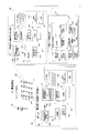
- the block diagram which shows the connection relation of the power transmission route state detection system in the modification of embodiment which concerns on this invention, a consumer, and a power distribution system.
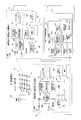
- the block diagram which shows the connection relation of the power transmission route state detection system in the modification of embodiment which concerns on this invention, a consumer, and a power distribution system.
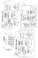
- the power transmission route state detection system 1 in the embodiment according to the present invention is a system that detects a state such as a failure or power theft in a power transmission route when power is interchanged between consumers in the mesh power network 51.
- the mesh power network 51 is connected to a power distribution system 50 from an electric power company.
- the power equipment of the consumer G is connected to the distribution line 55 drawn out from each of a plurality of intersections (referred to as nodes 52) of the distribution line 54 forming the mesh power network 51.
- a customer group 60 is constituted by a plurality of consumers G connected to such a mesh power network 51.
- the power configuration of the consumer G20 is shown as a power accommodation source, and the power configuration of the customer G30 is shown as a power accommodation destination.
- Other customers G have the same configuration as the customers G20 and G30.
- a consumer G20 that appears in the following description owns a power generation device (solar panel 21) and a storage battery (power storage device 23), and when power is insufficient, power is purchased from outside and surplus power is generated. You can sell power to the outside.
- the consumer G30 also has a power generation device (solar panel 31) and a storage battery (power storage device 33), similar to the customer G20.
- a consumer is a contract with an electric power company and is an individual, corporation, organization, etc. that uses electric power supplied from the electric power company via the grid 50 (see FIG. 1). , Condominiums), companies (business establishments, factories, facilities, etc.), local governments, national institutions, etc.
- the above-mentioned outside includes an electric power company and other customers. That is, as the outside from which the consumer G sells electricity, an electric power company, another consumer G, etc. are mentioned.
- the smart meters 28 and 38 (see FIG. 1) are installed in each consumer, measure the amount of power generation, the amount of electricity stored, and the amount of power consumption, and measure using the communication function. It means a measuring device that transmits the result to an electric power company.
- the electric power company can accurately grasp the real-time power situation in the consumers G20 and G30, and can automate the meter reading work performed every predetermined period.
- the loads 24 and 34 are, for example, power consumers such as air conditioners, refrigerators, power ranges, IH cooking heaters, and televisions when the consumer is a general household. I mean.
- power consumers such as air conditioners, refrigerators, power ranges, IH cooking heaters, and televisions when the consumer is a general household.
- I mean when a consumer is a company (a factory or the like), it means power consumers such as various facilities and air conditioning equipment installed in the factory.
- EMS (Energy Management System) 26 and 36 are installed in each consumer, and are provided to reduce power consumption in each consumer. Means.
- the surrounding connection relationship acquisition units 28 a and 38 a acquire the connection relationship of the switches 53 around the node 52 to which the surrounding connection relationship is acquired and transmit it to the power transmission route state detection device 10.
- FIG. 1 only the configuration of the two consumers G20 and G30 is shown, but the other customers also have the same configuration, and the switches 53 around the node 52 to which each is connected are shown.
- the connection relationship is acquired by the surrounding connection relationship acquisition unit and transmitted to the power transmission route state detection device 10.
- the surrounding connection relationship acquisition units 28a and 38a are provided in the smart meters 28 and 38 of the consumers G20 and G30.
- the switches 53 will be described later, they are arranged in each of the distribution lines 54 between the nodes 52 and turn on / off the electrical connection between the nodes 52.
- the power transmission amount transmission unit 22b transmits the power transmission amount transmitted from the customer G20 as the accommodation source to the customer G30 as the accommodation destination to the power transmission route state detection device 10.
- the power transmission amount transmission unit 22b is provided in the photovoltaic power generation power conversion device (PCS) 22 of the consumer G20.
- the PCS 22 converts electric power generated by the solar panel 21 described later from a direct current into an alternating current, and the converted electric power is used by the load 24 or sold to the outside. Further, the PCS 22 converts the voltage of the electric power generated in the solar panel 21, and the electric power whose voltage has been converted is stored in the power storage device 33.
- the power transmission amount transmission unit 22b is provided in the PCS 22, it is possible to transmit the electric power generated in the solar panel 21 and accommodated to other consumers G30 to the power transmission route state detection device 10. Note that the power generated by the solar panel 21 can be sold, but the power once stored in the power storage device 23 cannot be sold. Therefore, the power transmission amount transmission unit 22b may be provided in the PCS 22.
- the smart meter 38 measures the power actually received by the customer G30 as the accommodation destination and transmits it to the power transmission route state detection device 10.
- the power transmission amount transmission unit 32b is also provided in the photovoltaic power generation amount power conversion device (PCS32) of the consumer G30.
- PCS32 photovoltaic power generation amount power conversion device
- a consumer G20 includes a solar panel (power generation device) 21, a solar power generation power conversion device (PCS) 22, a power generation power sensor 22a, a power storage device (storage battery) 23, and power for stored power.
- a sensor 23a, a load 24, a load power sensor 24a, a distribution board 25, an EMS (Energy Management System) 26, and a smart meter 28 are provided.
- the continuous line which connects each structure in the consumer G shown in FIG. 1 has shown the flow of information, such as data, and the dashed-dotted line has shown the flow of electricity.
- the distribution line 54 is outside the customer G and is shown by a solid line.
- the solar panel (power generation device) 21 is a device that generates electricity using the photovoltaic effect using the light energy of sunlight, and is installed on the roof or the like of the consumer G20. And the electric power generation amount in the solar panel 21 can be estimated based on the information regarding the sunshine time of a weather forecast.
- a photovoltaic power generation converter (PCS (Power Conditioning System)) 22 is connected to a solar panel 21 and converts a direct current generated in the solar panel 21 into an alternating current.
- the generated power sensor 22 a is connected to the solar power converter 22 and measures the power generated in the solar panel 21.
- the generated power sensor 22 a transmits the measurement result (power generation amount) to the EMS 26.
- the power storage device (storage battery) 23 is provided to temporarily store surplus power that cannot be consumed by the load 24 among the power generated by the solar panel 21. As a result, even when the amount of power consumed by the load 24 is small during the daytime when power is generated by the solar panel 21, the excess power is stored in the power storage device 23 so that the generated power is discarded. Can be eliminated.
- the stored power sensor 23 a is connected to the power storage device 23 and measures the power stored in the power storage device 23. Then, the stored power sensor 23a transmits a measurement result (amount of storage) to the EMS 26.
- the load 24 is a power consumer such as a home appliance such as an air conditioner or a refrigerator in a general household, equipment in a factory, an air conditioner, and the like. The power generated by 21 and the power stored in power storage device 23 are consumed.
- the load power sensor 24 a is connected to the load 24 and measures the power consumed by the load 24. Then, the load power sensor 24 a transmits a measurement result (power consumption) to the EMS 26.
- the distribution board 25 is connected to a power sensor for generated power 22 a, a power sensor for stored power 23 a, a power sensor for load 24 a, and a smart meter 28. The distribution board 25 supplies the load 24 with the power generated by the solar panel 21, the power stored in the power storage device 23, or the power purchased from the system 50.
- the distribution board 25 supplies surplus power to the system 50 via the smart meter 28.
- consumer G20 can sell surplus electric power to an electric power company or other consumer G.
- the EMS (Energy Management System) 26 is an energy management system provided to reduce power consumption in the consumer G20. As shown in FIG. It is connected to the power sensor 23a for power and the power sensor 24a for load. Further, the EMS 26 efficiently supplies the load 24 with the power generated by the solar panel 21 and the amount of power stored in the power storage device 23 using the detection results received from the sensors 22a, 23a, and 24a. Thereby, the consumption of the electric power supplied from the system
- the smart meter 28 measures the power generation amount of the solar panel 21 owned by the customer G20, the power storage amount of the power storage device 23, and the power consumption of the load 24. And the smart meter 28 is connected with each sensor 22a, 23a, 24a via the distribution board 25, as shown in FIG. Furthermore, the smart meter 28 has a communication function, and transmits information on the amount of power generation, the amount of electricity stored, and the power consumption in the consumer G20 to the power company.
- the consumer G30 also has the same configuration as the consumer G20. As shown in FIG. 1, the consumer G30 includes a solar panel (power generation device) 31, a photovoltaic power generation conversion device (PCS) 32, a power generation power sensor 32a, a power storage device (storage battery) 33, and power for stored power.
- a sensor 33a, a load 34, a load power sensor 34a, a distribution board 35, an EMS (Energy Management System) 36, and a smart meter 38 are provided.
- the power transmission route state detection device 10 includes a first power acquisition unit 11, a second power acquisition unit 12, a power transmission route determination unit 13, and a state estimation unit 14.
- a first power acquisition unit 11 a second power acquisition unit 12
- a power transmission route determination unit 13 a state estimation unit 14.
- the case where power is supplied from the consumer G20 to the consumer G30 will be described as an example, but the reverse may be possible.
- the 1st electric power acquisition part 11 receives the information of the electric power which the consumer G20 of the power interchange origin transmits to the consumer G30 of the accommodation destination from the transmission amount transmission part 22b of the consumer G30.
- Communication between the first power acquisition unit 11 and the power transmission amount transmission unit 22b may be wired or wireless, and may be via the Internet or the like.
- the 1st electric power acquisition part 11 receives the information of the electric power transmitted from the transmission amount transmission part of the consumer G.
- the second power acquisition unit 12 receives, from the smart meter 38, information on the power received by the consumer G30 as a power interchange destination. Communication between the second power acquisition unit 12 and the smart meter 38 may be either wired or wireless, and may be via the Internet or the like.
- the 2nd electric power acquisition part 12 receives the information of the electric power received from the smart meter of the consumer G.
- the power transmission route determination unit 13 determines a power transmission route for transmitting power from the customer G20 as the accommodation source to the customer G30 as the accommodation destination.
- the power transmission route determination unit 13 includes a connection state acquisition unit 131, a power transmission route extraction unit 132, a storage unit 133, an assumed power transmission loss calculation unit 134, and a power transmission route selection unit 135.
- the connection state acquisition unit 131 acquires information regarding the switch 53 existing around the node 52 to which each customer G is connected from each customer G, and determines the connection state of the switch 53 in the mesh power network 51. get. Then, the connection state acquisition unit 131 records the connection state of the switch 53 in the connection relation databases 136a and 136b stored in the storage unit 133.
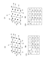
- FIG. 2 (a) to 2 (d) are diagrams for explaining the connection state of the switch 53 in the mesh power network 51.
- FIG. 2B and 2D show the connection relation databases 136a and 136b of the mesh power network 51 acquired by the connection state acquisition unit 131.
- FIG. The connection relation database 136a in FIG. 2B is a diagram showing the state of the colored switch 53 shown in FIG. For example, the switch 53 in column a in the 1-2 row in FIG. 2B is off, and this switch 53 is shown as a switch 53 ′ in FIG.
- the connection relation database 136b in FIG. 2D shows the state of the colored switch 53 shown in FIG. For example, the switch 53 in the ab column of one row in FIG. 2D is off, and this switch 53 is shown as a switch 53 ′′ in FIG.
- the power transmission route extraction unit 132 From the state of the switch 53 in the mesh-type power network 51 acquired by the connection state acquisition unit 131, the power transmission route extraction unit 132 starts from the customer G20 (node 52 in the first row and d column) as the customer G30 (from the accommodation source). A power transmission route capable of transmitting power to the node 52) in the fourth row and a column is extracted. 2 (a) to 2 (d), since the distribution line 54 with the switch 53 turned off cannot be selected as a power transmission route, the power transmission route extraction unit 132 extracts a plurality of power transmission route candidates as shown in FIG. To do.
- the power transmission route extraction unit 132 extracts a plurality of power transmission route candidates that can reach the customer G as the accommodation destination from the customer G as the accommodation source based on the state of the switch 53.
- the storage unit 133 stores the transmission line databases 137a and 137b of the distribution lines 54 between the nodes 52 together with the connection relation databases 136a and 136b.
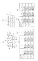
- 4B and 4D are diagrams showing power transmission line databases 137a and 137b stored in the storage unit 133.
- FIG. FIG. 4A is a diagram for explaining the power transmission line database 137a of FIG.
- the power transmission line database 137a in FIG. 4B shows information on the thick distribution lines 54 in FIG. For example, the information about the distribution line 54 'between the first row a column and the second row a column in FIG. 4 (a) is shown as 1-2 row a column in FIG. It is shown as 0.3 ⁇ / km and a thickness of 60 mm 2 .
- the transmission line database 137b of FIG.4 (d) shows the information of the thick distribution line of FIG.4 (c).
- the information about the distribution line 54 ′′ between the 4th row c column and the 4th row d column in FIG. 4C is shown as 4 rows cd column in FIG. 9 km, resistance 0.2 ⁇ / km, thickness 100 mm 2 are shown.
- the assumed power transmission loss calculation unit 134 calculates a power loss assumed for each power transmission route candidate extracted by the power transmission route extraction unit 132 based on the power transmission line databases 137a and 137b.
- the assumed power transmission loss amount is estimated by the following power transmission loss estimation formulas (Formula 1) and (Formula 2) using information stored in the power transmission line databases 137a and 137b.
- the power transmission route selection unit 135 selects one power transmission route from among the plurality of power transmission routes extracted by the power transmission route extraction unit 132 based on the assumed power transmission loss calculated by the assumed power transmission loss calculation unit 134. Specifically, the power transmission route selection unit 135 selects a power transmission route candidate having the smallest assumed power transmission loss as a power transmission route.
- the state estimation unit 14 includes a loss calculation unit 141, a determination unit 142, and an assumed power loss acquisition unit 143.
- the loss calculation unit 141 includes the power transmitted by the consumer G20 acquired by the first power acquisition unit 11 and the power actually received by the consumer G30 acquired by the second power acquisition unit 12. From this, the actual transmission loss is calculated.
- the assumed power loss acquisition unit 143 acquires the assumed transmission loss amount in the power transmission route calculated by the assumed transmission loss calculation unit 134.
- the determination unit 142 compares the actual power transmission loss amount with the estimated power transmission loss amount acquired by the assumed power loss acquisition unit 143, and determines whether power transmission is normally performed. For example, when it is determined that there is an abnormality, it is considered that a failure or theft has occurred due to any distribution line 54 or switch 53 in the power transmission route. ⁇ Operation> The operation of the power transmission route state detection system according to the embodiment of the present invention will be described below, and an example of the power transmission route state estimation method of the present invention will also be described.
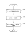
- FIG. 5 is a flowchart showing the operation of the power transmission route state estimation method according to the embodiment of the present invention.
- the consumer G20 as the power interchange source and the consumer G30 as the interchange destination are selected in advance based on the power that can be supplied and the demand amount for each consumer.
- Information on the customers of the accommodation source and the accommodation destination is transmitted to the power transmission route extraction unit 132 from the device that automatically selects the accommodation source and the accommodation destination or the device in which the operator inputs the accommodation source and the accommodation destination.
- the connection state acquisition unit 131 acquires a connection relationship between the nodes 52 (also referred to as smart meters) of the mesh power network 51. Specifically, the connection state of the surrounding switch 53 is acquired from the smart meters of all the consumers connected to the mesh type power network 51, and recorded in the connection relation databases 136a and 136b (see FIG. 2). Note that the connection state acquisition unit 131 may acquire only the connection state from the consumer G that is an accommodation source to the consumer G that is an accommodation destination.
- the accommodation source is the customer in the c column 2nd row and the accommodation destination is the customer in the b column 3rd row
- the b row 2 between the c column and the b column 2
- the state of the switch 53 is acquired between the second and third rows, between the second and third rows of the c column, and between the third column c and b columns.
- step S20 the power transmission route determination unit 13 uses the connection state from the accommodation source to the accommodation destination stored in the connection relation databases 136a and 136b and the information on the distribution line 54 stored in the transmission line databases 137a and 137b. Based on this, a power transmission route is determined by a power transmission route determination flow described later.
- Step S20 corresponds to an example of a power transmission route acquisition step.
- step S30 the state estimation unit 14 based on the assumed transmission loss amount in the transmission route determined by the state estimation flow described later and the actual transmission loss amount calculated from the actually accommodated power, Estimate the determined power transmission route status (abnormality, power theft, etc.).
- FIG. 6 is a diagram showing a power transmission route determination flow, and shows details of step S20 of FIG.
- step S21 the power transmission route extraction unit 132 acquires information on the customer G20 that is a preset power source and the customer G30 that is a preset destination as described above.
- step S22 the power transmission route extraction unit 132 can transmit power from the customer G20 as the accommodation source to the customer G30 as the accommodation destination based on the connection relation databases 136a and 136b ( (See FIG. 3).
- step S23 the assumed power transmission loss calculation unit 134 calculates a power loss assumed for each power transmission route candidate extracted by the power transmission route extraction unit 132 based on the power transmission line databases 137a and 137b.
- step S ⁇ b> 24 the power transmission route selection unit 135 determines the transmission loss of the plurality of power transmission route candidates extracted by the power transmission route extraction unit 132 based on the assumed power transmission loss calculated by the assumed power transmission loss calculation unit 134. The smallest power transmission route candidate is selected as the power transmission route.
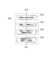
- FIG. 7 is a diagram showing a state estimation flow, and shows details of step S30 in FIG.
- the second power acquisition unit 12 receives, from the smart meter 38, information on the power received by the consumer G30 as a power accommodation destination.
- Step S23 corresponds to an example of a second power acquisition step.
- step S ⁇ b> 32 the first power acquisition unit 11 receives, from the power transmission amount transmission unit 22 b of the consumer G ⁇ b> 30, information on the power transmitted from the consumer G ⁇ b> 20 as the power interchange source to the consumer G ⁇ b> 30 as the accommodation destination.
- Step S32 corresponds to an example of a first power acquisition step.
- step S ⁇ b> 33 the loss calculation unit 141 uses the power transmitted by the consumer G20 of the source acquired by the first power acquisition unit 11 and the customer of the destination acquired by the second power acquisition unit 12. The difference of the power actually received by G30 is calculated, and the actual transmission loss amount is calculated.
- step S ⁇ b> 34 the determination unit 142 acquires the estimated power transmission loss amount in the power transmission route calculated and determined by the assumed power transmission loss calculation unit 134 from the power transmission route determination unit 13.
- step S35 the determination unit 142 calculates a loss rate.
- the loss rate is calculated by the following (Formula 3).
- step S36 the determination unit 142 determines whether or not the loss rate is smaller than ⁇ 3%.
- step S36 when the loss rate is smaller than ⁇ 3%, the determination unit 142 performs abnormality detection in step S37, assuming that the actual transmission loss amount is larger than the assumed transmission loss amount.
- step S36 determines that the actual transmission loss amount is within the allowable range of the assumed loss amount and is normal.
- steps S33 to S36 correspond to a state estimation step.
- the present invention may be realized as a power transmission route state estimation method program that causes a computer to execute a power transmission route state estimation method that is performed according to the flowcharts shown in FIGS. 5, 6, and 7.
- one usage form of the power transmission route state estimation program may be an aspect in which the program is recorded on a recording medium such as a ROM readable by a computer and operates in cooperation with the computer.
- one use form of the power transmission route state estimation program is a mode in which it is transmitted through a transmission medium such as the Internet and a transmission medium such as light, radio wave, and sound wave, and is read by a computer and operates in cooperation with the computer.
- a transmission medium such as the Internet
- a transmission medium such as light, radio wave, and sound wave
- the computer described above is not limited to hardware such as a CPU, and may include firmware, an OS, and peripheral devices.
- the power transmission route state estimation may be realized by software or may be realized by hardware.
- the power transmission route state detection apparatus 10 may be a virtual server in the cloud computing system, and a power transmission route state estimation program may be executed by the virtual server.
- the smart meters 28 and 38 are connected to the distribution line 55 drawn from the node 52 where the distribution line 54 of the mesh type power network 51 intersects. As shown in FIG. In addition, the smart meters 28 and 38 may be arranged at the node 52 where the distribution line 54 intersects.
- the smart meter of the consumer G By arranging the smart meter of the consumer G connected to the mesh power network 51 at the node 52, the power can be obtained for each node 52. For this reason, the state of the distribution line 54 between the nodes 52 (between smart meters) can be estimated.
- the smart meter of the consumer G is connected to the distribution line 55 drawn from the node 52. Therefore, the node 52 through which electricity other than the accommodation source and the accommodation destination passes cannot obtain current and cannot detect the power.
- the smart meter is arranged at the node 52, and therefore the node through which electricity passes. At 52, the current can be measured and the power can be detected.
- a state can be estimated for every distribution line 54 between the nodes 52, and the location (distribution line 54) where the failure of the power transmission route or theft of power has occurred can be estimated.
- a distribution line 54, a distribution line 54 between the fourth row and the dc column, a distribution line 54 between the fourth row and the bc column, and a distribution line 54 between the fourth row and the bb column, respectively. Can be detected.
- the first power acquisition unit 11 receives power from the smart meters of all the consumers G connected to the node 52 on the power transmission route. Then, the assumed power transmission loss calculation unit 134 calculates the power transmission loss amount assumed for each distribution line 54 up to the consumer G. For example, when the determination unit 142 determines the state of the distribution line 54 between the first and second rows of the d column from the customer G20, the state of the distribution line 54 between the second and third rows of the d column is next. Are determined for each distribution line 54 until the customer G20 is reached. For example, when determining the state of the distribution line 54 between the first and second rows of the d column, step S30 shown in FIG.
- voltmeters 128 and 138 may be provided instead of the smart meters 28 and 38 to detect the power at each node 52.
- the voltmeters 128 and 138 can measure the phase of the voltage and detect power from the phase. For this reason, electric power can be calculated without measuring the current.
- the state can be estimated for each distribution line 54 between the nodes 52 on the power transmission route, as in (B) above.
- the power transmission route determination unit 13 an example of the power transmission route acquisition unit
- the power transmission route state detection device 10 determines the power transmission route, but the power transmission route state detection device 10 does not determine the power transmission route. Also good. That is, the power transmission route state detection device 10 may only acquire the power transmission route determined externally and detect the state of the power transmission route.
- the state estimation unit 14 includes the loss calculation unit 141 and the assumed power loss acquisition unit 143, but the loss calculation unit 141 and the assumed power loss acquisition unit 143 are provided in the state estimation unit 14. It does not have to be.
- the power transmission amount transmission units 22b and 32b are provided in the PCSs 32 and 33.
- the present invention is not limited to this, and may be provided in the EMS 36 and the smart meters 28 and 38.
- the power transmission route state detection device, the power transmission route state detection system, the power transmission route state detection method, the power transmission route state detection program, and the power conversion device of the present invention have an effect capable of detecting a power route failure or power theft, Widely applicable in consumer groups.
- power transmission route state detection system 10 power transmission route state detection device 11: first power amount acquisition unit 12: second power amount acquisition unit 13: power transmission route determination unit (an example of a power transmission route acquisition unit) 14: State estimation unit 21: Solar panel 22: Photovoltaic power conversion device (an example of a power conversion device) 22a: Power sensor for generated power 22b: Transmission amount transmission unit (an example of a first transmission unit) 23: Power storage device 23a: Power sensor for stored power 24: Load 24a: Power sensor for load 25: Distribution board 26: EMS 28: Smart meter 28a: Ambient connection relation acquisition unit 31: Solar panel 32a: Power sensor for generated power 32b: Transmission amount transmission unit 33: Power storage device 33a: Power sensor for stored power 34: Load 34a: Power sensor for load 35: Distribution board 36: EMS 38: Smart meter (an example of a detection unit, an example of a second transmission unit) 38a: Ambient connection relation acquisition unit 50: Distribution system 51: Mesh type power network 52: Node 53: Switch 53 ':
Landscapes
- Engineering & Computer Science (AREA)
- Power Engineering (AREA)
- Business, Economics & Management (AREA)
- Health & Medical Sciences (AREA)
- Economics (AREA)
- Primary Health Care (AREA)
- Tourism & Hospitality (AREA)
- General Health & Medical Sciences (AREA)
- Human Resources & Organizations (AREA)
- Marketing (AREA)
- Public Health (AREA)
- Strategic Management (AREA)
- Water Supply & Treatment (AREA)
- Physics & Mathematics (AREA)
- General Business, Economics & Management (AREA)
- General Physics & Mathematics (AREA)
- Theoretical Computer Science (AREA)
- Remote Monitoring And Control Of Power-Distribution Networks (AREA)
- Management, Administration, Business Operations System, And Electronic Commerce (AREA)
- Supply And Distribution Of Alternating Current (AREA)
Abstract
送電ルート状態検出装置(10)は、送電ルート決定部(13)と、第1電力量取得部(11)と、第2電力量取得部(12)と、状態推定部(14)と、を備える。送電ルート決定部(13)は、メッシュ型電力網(51)のノード(52)に接続された需要家間で電力の融通を行う送電ルートを決定する。第1電力量取得部(11)は、融通元の需要家(G20)が送電する電力量を取得する。第2電力量取得部(12)は、融通先の需要家(G30)が融通元の需要家(G20)から送電された電力量を取得する。状態推定部(14)は、第1電力量取得部(11)により取得された電力量と第2電力量取得部(12)により取得された電力量に基づいて、決定された送電ルートの状態を推定する。
Description
本発明は、送電ルート状態検出装置、送電ルート状態検出システム、送電ルート状態検出方法、送電ルート状態検出プログラム、および電力変換装置に関する。
近年、再生可能エネルギーを利用して発電する発電電力装置(例えば、太陽光発電装置)が活用されている。わが国においては、余剰電力買い取り制度が制定されているため、太陽光発電装置や風力発電装置等で発電された電力を電力会社に売ることができる。
また、発電された電力を電力会社に売るだけでなく、不特定の需要家に売電するシステムが提案されている(例えば、特許文献1参照。)。
また、発電された電力を電力会社に売るだけでなく、不特定の需要家に売電するシステムが提案されている(例えば、特許文献1参照。)。
しかしながら、上記特許文献1には、送電ルートに不具合が存在する場合や盗電されている場合に、それらを検出することができない。
特に、メッシュ型電力網が形成され需要家間で電力を融通しあうことが可能な場合では、送電可能なルートが複数存在することになり、需要家間における送電ルートの故障や盗電を検出することはより困難となる。
特に、メッシュ型電力網が形成され需要家間で電力を融通しあうことが可能な場合では、送電可能なルートが複数存在することになり、需要家間における送電ルートの故障や盗電を検出することはより困難となる。
本発明は、送電ルートの故障や盗電を検出することが可能な送電ルート状態検出装置、送電ルート状態検出システム、送電ルート状態検出方法、送電ルート状態検出プログラムおよび電力変換装置を提供することを目的とする。
(課題を解決するための手段)
第1の発明に係る送電ルート状態検出装置は、送電ルート取得部と、第1電力取得部と、第2電力取得部と、状態推定部と、を備える。送電ルート取得部は、メッシュ型電力網のノードに接続された需要家間で電力の融通を行う送電ルートを取得する。第1電力取得部は、融通元の需要家が送電する電力を取得する。第2電力取得部は、融通先の需要家が融通元の需要家から送電された電力を取得する。状態推定部は、第1電力取得部により取得された電力と第2電力取得部により取得された電力に基づいて、送電ルート取得部により取得された送電ルートの状態を推定する。
(課題を解決するための手段)
第1の発明に係る送電ルート状態検出装置は、送電ルート取得部と、第1電力取得部と、第2電力取得部と、状態推定部と、を備える。送電ルート取得部は、メッシュ型電力網のノードに接続された需要家間で電力の融通を行う送電ルートを取得する。第1電力取得部は、融通元の需要家が送電する電力を取得する。第2電力取得部は、融通先の需要家が融通元の需要家から送電された電力を取得する。状態推定部は、第1電力取得部により取得された電力と第2電力取得部により取得された電力に基づいて、送電ルート取得部により取得された送電ルートの状態を推定する。
このように、メッシュ型の電力網において電力の融通を行う際に、融通元から融通先へ電力を送る送電ルートを取得する。そして、融通元が送電した電力と融通先が受電した電力に基づいて、送電ルートの状態を推定することができる。
このため、例えば、融通元が送電した電力よりも融通先が受電した電力が少なくなっている場合、取得した送電ルートに故障や盗電などが発生していることを検出することができる。
このため、例えば、融通元が送電した電力よりも融通先が受電した電力が少なくなっている場合、取得した送電ルートに故障や盗電などが発生していることを検出することができる。
第2の発明に係る送電ルート状態検出装置は、第1の発明に係る送電ルート状態検出装置であって、需要家はメッシュ型電力網の配電線が交わるノードに接続され、送電ルート上であって、融通元の需要家が接続されているノードと、融通先の需要家が接続されているノードとの間には、送電の際に経由する1つ以上のノードが設けられている。第2電力取得部は、融通先の需要家が接続されているノードに加えて、経由する少なくとも1つのノードにおける電力を取得する。
このように、第2電力取得部は、融通元の需要家から融通先の需要家に至る送電ルート上の少なくとも1つのノードにおいて電力を取得する。このため、送電ルートの各ノード間において故障や盗電などが発生していることを検出できる。
第3の発明に係る送電ルート状態検出装置は、第1の発明に係る送電ルート状態検出装置であって、第1電力取得部は、融通元の需要家が送電する電力を、融通元の需要家の送信部から通信によって取得する。
第3の発明に係る送電ルート状態検出装置は、第1の発明に係る送電ルート状態検出装置であって、第1電力取得部は、融通元の需要家が送電する電力を、融通元の需要家の送信部から通信によって取得する。
このように、第1電力取得部は、融通元の需要家が送る送電量を通信によって取得できる。
例えば、融通元の需要家の電力変換装置(パワーコンディショニング装置)に送信部が設けられており、この送信部と第1電力取得部が通信を行うことができる。
第4の発明に係る送電ルート状態検出装置は、第1の発明に係る送電ルート状態検出装置であって、想定電力損失取得部と、損失算出部と、を更に備える。想定電力損失取得部は、融通元の需要家が接続されている前記ノードと融通先の需要家が接続されているノードとの間において想定される電力損失を取得する。損失算出部は、第1電力取得部により取得された電力と第2電力取得部により取得された電力の差分から実際の電力損失量を算出する。判定部は、損失量算出部によって算出された実際の電力損失量と、想定電力損失取得部によって取得された想定電力損失量とを比較して送電ルートの状態が正常か否かを判定する。
例えば、融通元の需要家の電力変換装置(パワーコンディショニング装置)に送信部が設けられており、この送信部と第1電力取得部が通信を行うことができる。
第4の発明に係る送電ルート状態検出装置は、第1の発明に係る送電ルート状態検出装置であって、想定電力損失取得部と、損失算出部と、を更に備える。想定電力損失取得部は、融通元の需要家が接続されている前記ノードと融通先の需要家が接続されているノードとの間において想定される電力損失を取得する。損失算出部は、第1電力取得部により取得された電力と第2電力取得部により取得された電力の差分から実際の電力損失量を算出する。判定部は、損失量算出部によって算出された実際の電力損失量と、想定電力損失取得部によって取得された想定電力損失量とを比較して送電ルートの状態が正常か否かを判定する。
これにより、実際の電力損失量が、想定される電力損失量よりも大きい場合に、送電ルートに故障や盗電などが発生していることを検出することができる。
第5の発明に係る送電ルート状態検出装置は、第1の発明に係る送電ルート状態検出装置であって、メッシュ型電力網のノードから引き出された配電線には、電力を検出する検出部が接続されている。第2電力取得部は、メッシュ型電力網のノードから引き出された配電線に接続された検出部からノードにおける電力を取得する。
第5の発明に係る送電ルート状態検出装置は、第1の発明に係る送電ルート状態検出装置であって、メッシュ型電力網のノードから引き出された配電線には、電力を検出する検出部が接続されている。第2電力取得部は、メッシュ型電力網のノードから引き出された配電線に接続された検出部からノードにおける電力を取得する。
これにより、第2電力取得部は、融通先の需要家が受電した電力を取得することができ、送電ルートの状態を推定することができる。
第6の発明に係る送電ルート状態検出装置は、第1または第2の発明に係る送電ルート状態検出装置であって、メッシュ型電力網のノードには、電力を検出する検出部が配置されており、第2電力取得部は、検出部からノードにおける電力を取得する。
第6の発明に係る送電ルート状態検出装置は、第1または第2の発明に係る送電ルート状態検出装置であって、メッシュ型電力網のノードには、電力を検出する検出部が配置されており、第2電力取得部は、検出部からノードにおける電力を取得する。
このようにノードに検出部が配置されているため、電力は検出部を経由して融通先の需要家へ送電されることになり、ノードにおける電流値および電圧値を測定できる。そのため、第2電力取得部は、送電ルート上の各ノードにおける電力を取得でき、送電ルートのノード間における状態を推定することができる。
第7の発明に係る送電ルート状態検出装置は、第1または第2の発明に係る送電ルート状態検出装置であって、メッシュ型電力網のノードから引き出された配電線には、電圧を計測して電力を検出する検出部が接続されており、第2電力取得部は、検出部からノードにおける電力を取得する。
第7の発明に係る送電ルート状態検出装置は、第1または第2の発明に係る送電ルート状態検出装置であって、メッシュ型電力網のノードから引き出された配電線には、電圧を計測して電力を検出する検出部が接続されており、第2電力取得部は、検出部からノードにおける電力を取得する。
ここで、送電ルート上の電力が経由するノードでは、電流値を取得できず電圧値のみを取得できるが、電圧の位相変動から電力を算出することができる。このため、第2電力取得部は、送電ルート上の各ノードにおける電力を取得でき、送電ルートの各ノード間における状態を推定することができる。
第8の発明に係る送電ルート状態検出装置は、第1の発明に係る送電ルート状態検出装置であって、送電ルート取得部は、接続状態取得部と、送電ルート抽出部と、記憶部と、想定送電損失算出部と、送電ルート選定部と、を有する。接続状態取得部は、メッシュ型電力網のノード間の接続状態を取得する。送電ルート抽出部は、取得した接続状態に基づいて、融通元の需要家と融通先の需要家の間の送電ルートの候補を抽出する。記憶部は、ノード間において想定されるノード間送電損失を記憶する。想定送電損失算出部は、想定されるノード間送電損失に基づいて、抽出された送電ルートの候補ごとに想定されるルート送電損失を算出する。送電ルート選定部は、想定されるルート送電損失に基づいて、送電ルートを選定する。
第8の発明に係る送電ルート状態検出装置は、第1の発明に係る送電ルート状態検出装置であって、送電ルート取得部は、接続状態取得部と、送電ルート抽出部と、記憶部と、想定送電損失算出部と、送電ルート選定部と、を有する。接続状態取得部は、メッシュ型電力網のノード間の接続状態を取得する。送電ルート抽出部は、取得した接続状態に基づいて、融通元の需要家と融通先の需要家の間の送電ルートの候補を抽出する。記憶部は、ノード間において想定されるノード間送電損失を記憶する。想定送電損失算出部は、想定されるノード間送電損失に基づいて、抽出された送電ルートの候補ごとに想定されるルート送電損失を算出する。送電ルート選定部は、想定されるルート送電損失に基づいて、送電ルートを選定する。
ここで、メッシュ型の電力網において需要家間で電力の融通を行う場合、ノード間の接続状態によって複数の送電ルートが存在することになるが、各送電ルートにおける送電損失を算出して送電損失の最も少ない送電ルート選択することで送電の効率を向上することができる。
第9の発明に係る送電ルート状態検出システムは、第1~4および8のいずれかの発明の送電ルート状態検出装置と、第1送信部と、検出部と、第2送信部とを備える。第1送信部は、第1電力取得部に、送電する電力を送信する。検出部は、ノードにおける電力を検出する。第2送信部は、検出した電力を第2電力取得部に送信する。
第9の発明に係る送電ルート状態検出システムは、第1~4および8のいずれかの発明の送電ルート状態検出装置と、第1送信部と、検出部と、第2送信部とを備える。第1送信部は、第1電力取得部に、送電する電力を送信する。検出部は、ノードにおける電力を検出する。第2送信部は、検出した電力を第2電力取得部に送信する。
これにより、融通元が送電した電力と、融通先の需要家が接続されているノードまたは送電ルートの途中のノードにおける電力を取得することができ、これらの電力に基づいて、送電ルートの状態を推定することができる。
第10の発明に係る送電ルート状態検出システムは、第5~7のいずれかの発明の送電ルート状態検出装置と、第1送信部と、検出部と、第2送信部とを備える。第1送信部は、第1電力取得部に、送電する電力を送信する。検出部は、ノードにおける電力を検出する。第2送信部は、検出した電力を第2電力取得部に送信する。
第10の発明に係る送電ルート状態検出システムは、第5~7のいずれかの発明の送電ルート状態検出装置と、第1送信部と、検出部と、第2送信部とを備える。第1送信部は、第1電力取得部に、送電する電力を送信する。検出部は、ノードにおける電力を検出する。第2送信部は、検出した電力を第2電力取得部に送信する。
これにより、融通元が送電した電力と、融通先の需要家が接続されているノードまたは送電ルートの途中のノードにおける電力を取得することができ、これらの電力に基づいて、送電ルートの状態を推定することができる。
第11の発明に係る電力変換装置は、メッシュ型電力網のノードに接続され電力の融通元の需要家が所有する電力変換装置であって、メッシュ型電力網の他のノードに接続された電力の融通先の需要家に送電する電力の情報を送信する送信部を備える。
第11の発明に係る電力変換装置は、メッシュ型電力網のノードに接続され電力の融通元の需要家が所有する電力変換装置であって、メッシュ型電力網の他のノードに接続された電力の融通先の需要家に送電する電力の情報を送信する送信部を備える。
このように電力変換装置が送電量を送信する送信部を備えることによって、融通先に送電した送電量に基づいて、送電ルートの故障や盗電等が発生せずに正常に送電されているか否かを検出することができる。
第12の発明に係る送電ルート状態検出方法は、送電ルート取得ステップと、第1電力取得ステップと、第2電力取得ステップと、状態推定ステップと、を備える。送電ルート取得ステップは、メッシュ型電力網のノードに接続された需要家間で電力の融通を行う送電ルートを取得する。第1電力取得ステップは、融通元の需要家が送電する電力を取得する。第2電力取得ステップは、融通先の需要家が融通元の需要家から送電された電力を取得する。状態推定ステップは、第1電力取得ステップにより取得された電力と第2電力取得ステップにより取得された電力に基づいて、送電ルート取得ステップにより取得された送電ルートの状態を推定する。
第12の発明に係る送電ルート状態検出方法は、送電ルート取得ステップと、第1電力取得ステップと、第2電力取得ステップと、状態推定ステップと、を備える。送電ルート取得ステップは、メッシュ型電力網のノードに接続された需要家間で電力の融通を行う送電ルートを取得する。第1電力取得ステップは、融通元の需要家が送電する電力を取得する。第2電力取得ステップは、融通先の需要家が融通元の需要家から送電された電力を取得する。状態推定ステップは、第1電力取得ステップにより取得された電力と第2電力取得ステップにより取得された電力に基づいて、送電ルート取得ステップにより取得された送電ルートの状態を推定する。
これにより、例えば、融通元が送電した電力よりも融通先が受電した電力が少なくなっている場合、決定した送電ルートに故障や盗電などが発生していることを検出することができる。
第13の発明に係る送電ルート状態検出プログラムは、送電ルート取得ステップと、第1電力取得ステップと、第2電力取得ステップと、状態推定ステップと、を備えた送電ルート状態検出方法をコンピュータに実行させる。送電ルート取得ステップは、メッシュ型電力網のノードに接続された需要家間で電力の融通を行う送電ルートを取得する。第1電力取得ステップは、融通元の需要家が送電する電力を取得する。第2電力取得ステップは、融通先の需要家が融通元の需要家から送電された電力を取得する。状態推定ステップは、第1電力取得ステップにより取得された電力と第2電力取得ステップにより取得された電力に基づいて、送電ルート取得ステップにより取得された送電ルートの状態を推定する。
第13の発明に係る送電ルート状態検出プログラムは、送電ルート取得ステップと、第1電力取得ステップと、第2電力取得ステップと、状態推定ステップと、を備えた送電ルート状態検出方法をコンピュータに実行させる。送電ルート取得ステップは、メッシュ型電力網のノードに接続された需要家間で電力の融通を行う送電ルートを取得する。第1電力取得ステップは、融通元の需要家が送電する電力を取得する。第2電力取得ステップは、融通先の需要家が融通元の需要家から送電された電力を取得する。状態推定ステップは、第1電力取得ステップにより取得された電力と第2電力取得ステップにより取得された電力に基づいて、送電ルート取得ステップにより取得された送電ルートの状態を推定する。
これにより、例えば、融通元が送電した電力よりも融通先が受電した電力が少なくなっている場合、決定した送電ルートに故障や盗電などが発生していることを検出することができる。
本発明によれば、送電ルートの故障や盗電を検出することが可能な送電ルート状態検出装置、送電ルート状態検出システム、送電ルート状態検出方法、送電ルート状態検出プログラムおよびパワーコンディショニング装置を提供することができる。
以下に、本発明に係る実施の形態における送電ルート状態検出装置、送電ルート状態検出システム、送電ルート状態検出方法、送電ルート状態検出プログラムおよびパワーコンディショニング装置について図面を参照して説明する。
本発明に係る実施の形態における送電ルート状態検出システム1は、メッシュ型電力網51において需要家間で電力の融通を行う際の送電ルートにおける故障や盗電などの状態を検出するシステムである。
本発明に係る実施の形態における送電ルート状態検出システム1は、メッシュ型電力網51において需要家間で電力の融通を行う際の送電ルートにおける故障や盗電などの状態を検出するシステムである。
図1に示すように、メッシュ型電力網51は、電力会社からの配電系統50に接続されている。このメッシュ型電力網51を形成する配電線54の複数の交点(ノード52という)のそれぞれから引き出された配電線55に需要家Gの電力設備が接続されている。このようなメッシュ型電力網51に接続されている複数の需要家Gによって需要家群60が構成されている。
図1では、電力の融通元として需要家G20の電力構成を示し、電力の融通先として需要家G30の電力構成を示している。他の需要家Gも需要家G20、G30と同様の構成である。
ここで、以下の説明において登場する需要家G20は、発電装置(ソーラーパネル21)と蓄電池(蓄電装置23)とを所有しており、電力が不足すると外部から電力を買い、余剰電力が生じると外部へと電力を売ることができる。
ここで、以下の説明において登場する需要家G20は、発電装置(ソーラーパネル21)と蓄電池(蓄電装置23)とを所有しており、電力が不足すると外部から電力を買い、余剰電力が生じると外部へと電力を売ることができる。
需要家G30も、需要家G20と同様に、発電装置(ソーラーパネル31)と蓄電池(蓄電装置33)を有している。
需要家とは、電力会社と契約を結んでおり、電力会社から系統50(図1参照)を介して供給される電力を使用する個人、法人、団体等であって、例えば、一般家庭(戸建て、マンション)、企業(事業所、工場、設備等)、地方自治体、国の機関等が含まれる。
需要家とは、電力会社と契約を結んでおり、電力会社から系統50(図1参照)を介して供給される電力を使用する個人、法人、団体等であって、例えば、一般家庭(戸建て、マンション)、企業(事業所、工場、設備等)、地方自治体、国の機関等が含まれる。
また、上述した外部とは、電力会社、他の需要家を含む。すなわち、需要家Gが売電する外部としては、電力会社、他の需要家G等が挙げられる。
そして、以下の実施の形態において、スマートメータ28、38(図1参照)とは、各需要家にそれぞれ設置され、発電量、蓄電量、電力消費量を計測し、通信機能を用いて、計測結果を電力会社等へ送信する計測機器を意味している。スマートメータ28、38を設置したことにより、電力会社は、需要家G20、G30におけるリアルタイムの電力状況を正確に把握できるとともに、所定期間ごとに実施される検針業務を自動化することができる。
そして、以下の実施の形態において、スマートメータ28、38(図1参照)とは、各需要家にそれぞれ設置され、発電量、蓄電量、電力消費量を計測し、通信機能を用いて、計測結果を電力会社等へ送信する計測機器を意味している。スマートメータ28、38を設置したことにより、電力会社は、需要家G20、G30におけるリアルタイムの電力状況を正確に把握できるとともに、所定期間ごとに実施される検針業務を自動化することができる。
更に、以下の実施の形態において、負荷24、34(図1参照)とは、例えば、需要家が一般家庭の場合には、エアコン、冷蔵庫、電力レンジ、IHクッキングヒータ、テレビ等の電力消費体を意味している。また、例えば、需要家が企業(工場等)の場合には、工場内に設置された各種設備、空調設備等の電力消費体を意味している。
更に、以下の実施の形態において、EMS(Energy Management System)26、36(図1参照)は、各需要家にそれぞれ設置されており、各需要家における消費電力を削減するために設けられたシステムを意味している。
更に、以下の実施の形態において、EMS(Energy Management System)26、36(図1参照)は、各需要家にそれぞれ設置されており、各需要家における消費電力を削減するために設けられたシステムを意味している。
(実施の形態)
<構成>
(送電ルート状態検出システム1の概要)
本発明に係る実施の形態の送電ルート状態検出システム1は、電力の融通元を需要家G20とし融通先を需要家G30とすると、送電ルート状態検出装置10と、周囲接続関係取得部28a、38aと、送電量送信部22bと、スマートメータ38とを備えている。
<構成>
(送電ルート状態検出システム1の概要)
本発明に係る実施の形態の送電ルート状態検出システム1は、電力の融通元を需要家G20とし融通先を需要家G30とすると、送電ルート状態検出装置10と、周囲接続関係取得部28a、38aと、送電量送信部22bと、スマートメータ38とを備えている。
周囲接続関係取得部28a、38aは、それぞれが接続されているノード52の周囲のスイッチ53の接続関係を取得し、送電ルート状態検出装置10へと送信する。なお、図1では、2つの需要家G20、30の構成のみを示しているが、他の需要家も同様の構成を有しており、それぞれが接続されているノード52の周囲のスイッチ53の接続関係が周囲接続関係取得部によって取得されて送電ルート状態検出装置10へと送信される。周囲接続関係取得部28a、38aは、需要家G20、G30のスマートメータ28、38内に設けられている。スイッチ53については後述するが、ノード52の間の配電線54のそれぞれに配置されており、ノード52間の電気的な接続のオン・オフを行う。
なお、需要家G20は、図1に示すメッシュ型電力網51の1行目のd列のノード52に接続されているため、周囲には、2つのスイッチ53しか存在しないが、例えば1行目のc列のノード52の周囲には3つのスイッチ53が存在し、2行目のc列のノード52の周囲には4つのスイッチ53が存在する。
送電量送信部22bは、融通元の需要家G20が融通先の需要家G30に送電した送電量を送電ルート状態検出装置10へ送信する。送電量送信部22bは、需要家G20の太陽光発電用電力変換装置(PCS)22に設けられている。PCS22は、後述するソーラーパネル21で発生した電力を直流電流から交流電流に変換し、変換された電力は負荷24で使用、または外部に売電される。また、PCS22は、ソーラーパネル21で発生した電力の電圧を変換し、電圧が変換された電力は蓄電装置33で蓄電される。
送電量送信部22bは、融通元の需要家G20が融通先の需要家G30に送電した送電量を送電ルート状態検出装置10へ送信する。送電量送信部22bは、需要家G20の太陽光発電用電力変換装置(PCS)22に設けられている。PCS22は、後述するソーラーパネル21で発生した電力を直流電流から交流電流に変換し、変換された電力は負荷24で使用、または外部に売電される。また、PCS22は、ソーラーパネル21で発生した電力の電圧を変換し、電圧が変換された電力は蓄電装置33で蓄電される。
送電量送信部22bがPCS22に設けられていることにより、ソーラーパネル21で発生し他の需要家G30に融通する電力を送電ルート状態検出装置10へと送信することができる。なお、ソーラーパネル21で発電された電力は売電できるが、一旦蓄電装置23に貯められた電力は売電することができないため、送電量送信部22bはPCS22に設けられていればよい。
スマートメータ38は、融通先の需要家G30が実際に受電した電力を計測し、送電ルート状態検出装置10へと送信する。
なお、需要家G30が融通元になる場合もあるため、需要家G30の太陽光発電量電力変換装置(PCS32)にも、送電量送信部32bが設けられている。
次に、需要家Gの電力機器の構成について説明し、本実施形態の送電ルート状態検出装置10の構成については後段において詳述する。
なお、需要家G30が融通元になる場合もあるため、需要家G30の太陽光発電量電力変換装置(PCS32)にも、送電量送信部32bが設けられている。
次に、需要家Gの電力機器の構成について説明し、本実施形態の送電ルート状態検出装置10の構成については後段において詳述する。
(需要家)
需要家G20は、図1に示すように、ソーラーパネル(発電装置)21、太陽光発電用電力変換装置(PCS)22、発電電力用電力センサ22a、蓄電装置(蓄電池)23、蓄電電力用電力センサ23a、負荷24、負荷用電力センサ24a、分電盤25、EMS(Energy Management System)26、およびスマートメータ28を備えている。なお、図1に示す需要家G内の各構成をつなぐ実線は、データ等の情報の流れを示しており、一点鎖線は電気の流れを示している。なお、配電線54については需要家G外であり、実線で示している。
需要家G20は、図1に示すように、ソーラーパネル(発電装置)21、太陽光発電用電力変換装置(PCS)22、発電電力用電力センサ22a、蓄電装置(蓄電池)23、蓄電電力用電力センサ23a、負荷24、負荷用電力センサ24a、分電盤25、EMS(Energy Management System)26、およびスマートメータ28を備えている。なお、図1に示す需要家G内の各構成をつなぐ実線は、データ等の情報の流れを示しており、一点鎖線は電気の流れを示している。なお、配電線54については需要家G外であり、実線で示している。
ソーラーパネル(発電装置)21は、太陽光の光エネルギーを用いた光起電力効果を利用して電気を発生させる装置であって、需要家G20の屋根等に設置されている。そして、ソーラーパネル21における発電量は、天気予報の日照時間に関する情報に基づいて予測することができる。
太陽光発電用電力変換装置(PCS(Power Conditioning System))22は、図1に示すように、ソーラーパネル21と接続されており、ソーラーパネル21において発生した直流電流を交流電流に変換する。
太陽光発電用電力変換装置(PCS(Power Conditioning System))22は、図1に示すように、ソーラーパネル21と接続されており、ソーラーパネル21において発生した直流電流を交流電流に変換する。
発電電力用電力センサ22aは、図1に示すように、太陽光発電用電力変換装置22に接続されており、ソーラーパネル21において発電した電力を測定する。そして、発電電力用電力センサ22aは、EMS26に対して測定結果(発電量)を送信する。
蓄電装置(蓄電池)23は、ソーラーパネル21において発電した電力のうち、負荷24によって消費しきれなかった余剰電力を一時的に蓄えるために設けられている。これにより、ソーラーパネル21によって発電する日中の時間帯において、負荷24による電力消費量が少ない場合でも、余った電力を蓄電装置23へ蓄えておくことで、発電した電力を捨ててしまう無駄を排除できる。
蓄電装置(蓄電池)23は、ソーラーパネル21において発電した電力のうち、負荷24によって消費しきれなかった余剰電力を一時的に蓄えるために設けられている。これにより、ソーラーパネル21によって発電する日中の時間帯において、負荷24による電力消費量が少ない場合でも、余った電力を蓄電装置23へ蓄えておくことで、発電した電力を捨ててしまう無駄を排除できる。
蓄電電力用電力センサ23aは、図1に示すように、蓄電装置23に接続されており、蓄電装置23において蓄えられている電力を測定する。そして、蓄電電力用電力センサ23aは、EMS26に対して測定結果(蓄電量)を送信する。
負荷24は、上述したように、一般家庭におけるエアコンや冷蔵庫等の家電製品、工場等における設備、空調装置等の電力消費体であって、電力会社100の電源110から供給される電力、ソーラーパネル21によって発生した電力、蓄電装置23において蓄えられた電力を消費する。
負荷24は、上述したように、一般家庭におけるエアコンや冷蔵庫等の家電製品、工場等における設備、空調装置等の電力消費体であって、電力会社100の電源110から供給される電力、ソーラーパネル21によって発生した電力、蓄電装置23において蓄えられた電力を消費する。
負荷用電力センサ24aは、図1に示すように、負荷24に接続されており、負荷24によって消費される電力を測定する。そして、負荷用電力センサ24aは、EMS26に対して測定結果(消費電力)を送信する。
分電盤25は、図1に示すように、発電電力用電力センサ22a、蓄電電力用電力センサ23a、負荷用電力センサ24a、およびスマートメータ28と接続されている。そして、分電盤25は、ソーラーパネル21において発電した電力、蓄電装置23に蓄えられた電力、または系統50から買った電力を負荷24に対して供給する。
分電盤25は、図1に示すように、発電電力用電力センサ22a、蓄電電力用電力センサ23a、負荷用電力センサ24a、およびスマートメータ28と接続されている。そして、分電盤25は、ソーラーパネル21において発電した電力、蓄電装置23に蓄えられた電力、または系統50から買った電力を負荷24に対して供給する。
また、分電盤25は、余剰電力を、スマートメータ28を介して系統50へと供給する。これにより、需要家G20は、電力会社または他の需要家Gに余剰電力を売電することができる。
EMS(Energy Management System)26は、上述したように、需要家G20における消費電力を削減するために設けられたエネルギー管理システムであって、図1に示すように、発電電力用電力センサ22a、蓄電電力用電力センサ23aおよび負荷用電力センサ24aと接続されている。また、EMS26は、各センサ22a,23a,24aから受信した検出結果を用いて、ソーラーパネル21による発電電力、蓄電装置23における蓄電量を効率よく負荷24に対して供給する。これにより、系統50から供給される電力の消費量を抑制して、需要家G20における電力コストを効果的に削減することができる。
EMS(Energy Management System)26は、上述したように、需要家G20における消費電力を削減するために設けられたエネルギー管理システムであって、図1に示すように、発電電力用電力センサ22a、蓄電電力用電力センサ23aおよび負荷用電力センサ24aと接続されている。また、EMS26は、各センサ22a,23a,24aから受信した検出結果を用いて、ソーラーパネル21による発電電力、蓄電装置23における蓄電量を効率よく負荷24に対して供給する。これにより、系統50から供給される電力の消費量を抑制して、需要家G20における電力コストを効果的に削減することができる。
スマートメータ28は、上述したように、需要家G20が所有するソーラーパネル21の発電量、蓄電装置23の蓄電量、および負荷24の消費電力を計測する。そして、スマートメータ28は、図1に示すように、分電盤25を介して各センサ22a,23a,24aと接続されている。更に、スマートメータ28は、通信機能を有しており、電力会社に対して、需要家G20における発電量、蓄電量、消費電力に関する情報を送信する。
なお、需要家G30も、需要家G20と同様の構成を備えている。
需要家G30は、図1に示すように、ソーラーパネル(発電装置)31、太陽光発電用電力変換装置(PCS)32、発電電力用電力センサ32a、蓄電装置(蓄電池)33、蓄電電力用電力センサ33a、負荷34、負荷用電力センサ34a、分電盤35、EMS(Energy Management System)36、およびスマートメータ38を備えている。
需要家G30は、図1に示すように、ソーラーパネル(発電装置)31、太陽光発電用電力変換装置(PCS)32、発電電力用電力センサ32a、蓄電装置(蓄電池)33、蓄電電力用電力センサ33a、負荷34、負荷用電力センサ34a、分電盤35、EMS(Energy Management System)36、およびスマートメータ38を備えている。
(送電ルート状態検出装置)
本実施の形態の送電ルート状態検出装置10は、第1電力取得部11と、第2電力取得部12と、送電ルート決定部13と、状態推定部14とを有する。
本実施の形態では、需要家G20から需要家G30に電力を供給する場合を例に挙げて説明するが、逆であってもよい。
本実施の形態の送電ルート状態検出装置10は、第1電力取得部11と、第2電力取得部12と、送電ルート決定部13と、状態推定部14とを有する。
本実施の形態では、需要家G20から需要家G30に電力を供給する場合を例に挙げて説明するが、逆であってもよい。
(第1電力取得部11)
第1電力取得部11は、電力の融通元の需要家G20が融通先の需要家G30に送電する電力の情報を、需要家G30の送電量送信部22bから受信する。第1電力取得部11と送電量送信部22bの間の通信は、有線および無線のいずれであってもよく、インターネット等を介していてもよい。
第1電力取得部11は、電力の融通元の需要家G20が融通先の需要家G30に送電する電力の情報を、需要家G30の送電量送信部22bから受信する。第1電力取得部11と送電量送信部22bの間の通信は、有線および無線のいずれであってもよく、インターネット等を介していてもよい。
また、他の需要家Gが電力の融通元となる場合には、第1電力取得部11は、その需要家Gの送電量送信部から送電する電力の情報を受信する。
(第2電力取得部12)
第2電力取得部12は、電力の融通先の需要家G30が受電した電力の情報をスマートメータ38から受信する。第2電力取得部12とスマートメータ38の間の通信は、有線および無線のいずれであってもよく、インターネット等を介していてもよい。
(第2電力取得部12)
第2電力取得部12は、電力の融通先の需要家G30が受電した電力の情報をスマートメータ38から受信する。第2電力取得部12とスマートメータ38の間の通信は、有線および無線のいずれであってもよく、インターネット等を介していてもよい。
また、他の需要家Gが電力の融通先となる場合には、第2電力取得部12は、その需要家Gのスマートメータから受電した電力の情報を受信する。
(送電ルート決定部13)
送電ルート決定部13は、融通元の需要家G20から融通先の需要家G30に電力を送る送電ルートを決定する。
(送電ルート決定部13)
送電ルート決定部13は、融通元の需要家G20から融通先の需要家G30に電力を送る送電ルートを決定する。
送電ルート決定部13は、接続状態取得部131と、送電ルート抽出部132と、記憶部133と、想定送電損失算出部134と、送電ルート選定部135と、を有する。
接続状態取得部131は、各々の需要家Gから、各々の需要家Gが接続されているノード52の周囲に存在するスイッチ53に関する情報を取得し、メッシュ型電力網51におけるスイッチ53の接続状態を取得する。そして、接続状態取得部131は、スイッチ53の接続状態を記憶部133が記憶している接続関係データベース136a、136bに記録する。
接続状態取得部131は、各々の需要家Gから、各々の需要家Gが接続されているノード52の周囲に存在するスイッチ53に関する情報を取得し、メッシュ型電力網51におけるスイッチ53の接続状態を取得する。そして、接続状態取得部131は、スイッチ53の接続状態を記憶部133が記憶している接続関係データベース136a、136bに記録する。
図2(a)~(d)は、メッシュ型電力網51におけるスイッチ53の接続状態を説明するための図である。図2(b)、(d)は、接続状態取得部131が取得したメッシュ型電力網51の接続関係データベース136a、136bを示す。図2(b)の接続関係データベース136aは、図2(a)に示す色付のスイッチ53の状態を示す図である。例えば、図2(b)の1-2行のa列のスイッチ53はオフであり、このスイッチ53は、図2(a)でスイッチ53´として示されている。また、図2(d)の接続関係データベース136bは、図2(c)に示す色付のスイッチ53の状態を示す。例えば、図2(d)の1行のa―b列のスイッチ53はオフであり、このスイッチ53は、図2(c)でスイッチ53´´として示されている。
送電ルート抽出部132は、接続状態取得部131で取得したメッシュ型電力網51におけるスイッチ53の状態から、融通元の需要家G20(1行目d列のノード52)から融通先の需要家G30(4行目a列のノード52)までの電力を送ることが可能な送電ルートを抽出する。図2(a)~(d)の接続状態では、スイッチ53がオフの配電線54は送電ルートとして選択できないため、送電ルート抽出部132は、図3に示すような複数の送電ルート候補を抽出する。例えば送電ルート候補のうち送電ルート1では、需要家G20が接続されている1行目d列のノード52から、d列を通って1行目から2行目まで移動し、d列を通って2行目から3行目まで移動し、d列を通って3行目から4行目まで移動し、4行目を通ってd列からc列まで移動し、4行目を通ってc列からb列まで移動し、4行目を通ってb列からa列まで移動することによって、需要家G30が接続されている4行目a列のノード52に到達する。このように、送電ルート抽出部132は、スイッチ53の状態に基づいて、融通元の需要家Gから融通先の需要家Gに到達することが可能な複数の送電ルート候補を抽出する。
記憶部133は、上記接続関係データベース136a、136bとともに、各ノード52間の配電線54の送電線データベース137a、137bを記憶している。図4(b)、(d)は、記憶部133に記憶されている送電線データベース137a、137bを示す図である。図4(a)は、図4(b)の送電線データベース137aを説明するための図である。図4(b)の送電線データベース137aは、図4(a)の太線の配電線54の情報を示す。例えば、図4(a)の1行目a列と2行目a列の間の配電線54´についての情報は、図4(b)では1-2行a列として、長さ1km、抵抗0.3Ω/km、太さ60mm2と示されている。また、図4(d)の送電線データベース137bは、図4(c)の太線の配電線の情報を示す。例えば、図4(c)の4行目c列と4行目d列の間の配電線54´´についての情報は、図4(d)では4行c-d列として、長さ1.9km、抵抗0.2Ω/km、太さ100mm2と示されている。
想定送電損失算出部134は、送電線データベース137a、137bに基づいて、送電ルート抽出部132によって抽出された送電ルート候補ごとに想定される電力損失を算出する。
なお、想定される送電損失量は、送電線データベース137a、137bに記憶されている情報を用いて、以下の送電損失推定式(式1)(式2)によって推定される。
なお、想定される送電損失量は、送電線データベース137a、137bに記憶されている情報を用いて、以下の送電損失推定式(式1)(式2)によって推定される。
(式1)想定送電損失量(P)=電流量(I2)×電線抵抗(R)
(式2)電線抵抗(R)=送電線ごとの抵抗ρ(Ω/km)×送電線ごとの長さL(km)
これによって、例えば、図3に示すように、送電ルート候補ごとに想定送電損失が算出される。
(式2)電線抵抗(R)=送電線ごとの抵抗ρ(Ω/km)×送電線ごとの長さL(km)
これによって、例えば、図3に示すように、送電ルート候補ごとに想定送電損失が算出される。
送電ルート選定部135は、想定送電損失算出部134によって算出された想定送電損失に基づいて、送電ルート抽出部132によって抽出された複数の送電ルートのうち1つの送電ルートを選択する。具体的には、送電ルート選定部135は、想定送電損失が最も小さい送電ルート候補を送電ルートとして選定する。
(状態推定部)
状態推定部14は、損失算出部141と、判定部142と、想定電力損失取得部143とを有している。
(状態推定部)
状態推定部14は、損失算出部141と、判定部142と、想定電力損失取得部143とを有している。
損失算出部141は、第1電力取得部11によって取得された融通元の需要家G20が送電した電力と、第2電力取得部12によって取得された融通先の需要家G30が実際に受電した電力から、実際の送電損失量を算出する。
想定電力損失取得部143は、想定送電損失算出部134によって算出された送電ルートにおける想定送電損失量を取得する。
想定電力損失取得部143は、想定送電損失算出部134によって算出された送電ルートにおける想定送電損失量を取得する。
判定部142は、実際の送電損失量と、想定電力損失取得部143によって取得された想定送電損失量を比較し、正常に送電が行われているか否かを判定する。例えば、異常と判定された場合には、送電ルートのいずれかの配電線54またはスイッチ53によって故障や盗電が発生していることが考えられる。
<動作>
以下に、本発明に係る実施の形態の送電ルート状態検出システムの動作を説明するとともに、本発明の送電ルート状態推定方法の一例についても述べる。
<動作>
以下に、本発明に係る実施の形態の送電ルート状態検出システムの動作を説明するとともに、本発明の送電ルート状態推定方法の一例についても述べる。
(全体フロー)
図5は、本発明に係る実施の形態における送電ルート状態推定方法の動作を示すフロー図である。
ここで、本実施の形態では、電力の融通元の需要家G20と融通先の需要家G30は、需要家ごとの供給可能な電力と需要量に基づいて予め選定されているものとする。そして融通元と融通先の自動選択を行う装置または融通元と融通先をオペレーター等が入力する装置から、融通元と融通先の需要家に関する情報が送電ルート抽出部132に送信される。
図5は、本発明に係る実施の形態における送電ルート状態推定方法の動作を示すフロー図である。
ここで、本実施の形態では、電力の融通元の需要家G20と融通先の需要家G30は、需要家ごとの供給可能な電力と需要量に基づいて予め選定されているものとする。そして融通元と融通先の自動選択を行う装置または融通元と融通先をオペレーター等が入力する装置から、融通元と融通先の需要家に関する情報が送電ルート抽出部132に送信される。
はじめに、ステップS10において、接続状態取得部131が、メッシュ型電力網51の各ノード52間(スマートメータ間ともいえる)の接続関係を取得する。詳しくは、メッシュ型電力網51に接続されている全ての需要家のスマートメータから、その周囲のスイッチ53の接続状態を取得し、接続関係データベース136a、136b(図2参照)に記録する。なお、接続状態取得部131は、融通元の需要家Gから融通先の需要家Gまでの接続状態のみを取得しても良い。この場合、例えば、融通元がc列2行目の需要家であり、融通先がb列3行目の需要家である場合、2行目のc列とb列の間、b列の2行目と3行目の間、c列の2行目と3行目の間、および3行目のc列とb列の間のスイッチ53の状態が取得される。
次に、ステップS20において、送電ルート決定部13が、接続関係データベース136a、136bに記憶された融通元から融通先までの接続状態および送電線データベース137a、137bに記憶された配電線54の情報に基づいて、後述する送電ルート決定フローによって送電ルートを決定する。ステップS20が、送電ルート取得ステップの一例に対応する。
次に、ステップS30において、状態推定部14が、後述する状態推定フローによって決定した送電ルートにおける想定送電損失量と、実際に融通された電力から算出された実際の送電損失量とに基づいて、決定した送電ルートの状態(異常、盗電等)を推定する。
(送電ルート決定フロー)
図6は、送電ルート決定フローを示す図であり、図5のステップS20を詳細に示す図である。
(送電ルート決定フロー)
図6は、送電ルート決定フローを示す図であり、図5のステップS20を詳細に示す図である。
ステップS10の後、ステップS21において、送電ルート抽出部132は、上述したように予め設定され送信されてくる電力の融通元の需要家G20と融通先の需要家G30の情報を取得する。
次に、ステップS22において、送電ルート抽出部132が、接続関係データベース136a、136bに基づいて、融通元の需要家G20から融通先の需要家G30までの電力を送ることが可能な送電ルート候補(図3参照)を抽出する。
次に、ステップS22において、送電ルート抽出部132が、接続関係データベース136a、136bに基づいて、融通元の需要家G20から融通先の需要家G30までの電力を送ることが可能な送電ルート候補(図3参照)を抽出する。
次に、ステップS23において、想定送電損失算出部134が、送電線データベース137a、137bに基づいて、送電ルート抽出部132によって抽出された送電ルート候補ごとに想定される電力損失を算出する。
次に、ステップS24において、送電ルート選定部135は、想定送電損失算出部134によって算出された想定送電損失に基づいて、送電ルート抽出部132によって抽出された複数の送電ルート候補のうち送電損失の最も小さい送電ルート候補を送電ルートとして選択する。
次に、ステップS24において、送電ルート選定部135は、想定送電損失算出部134によって算出された想定送電損失に基づいて、送電ルート抽出部132によって抽出された複数の送電ルート候補のうち送電損失の最も小さい送電ルート候補を送電ルートとして選択する。
(状態推定ステップ)
図7は、状態推定フローを示す図であり、図5のステップS30を詳細に示す図である。
ステップS24(ステップS20)の後、ステップS31において、第2電力取得部12が、電力の融通先の需要家G30が受電した電力の情報をスマートメータ38から受信する。ステップS23が、第2電力取得ステップの一例に対応する。
図7は、状態推定フローを示す図であり、図5のステップS30を詳細に示す図である。
ステップS24(ステップS20)の後、ステップS31において、第2電力取得部12が、電力の融通先の需要家G30が受電した電力の情報をスマートメータ38から受信する。ステップS23が、第2電力取得ステップの一例に対応する。
次に、ステップS32において、第1電力取得部11が、電力の融通元の需要家G20が融通先の需要家G30に送電する電力の情報を、需要家G30の送電量送信部22bから受信する。ステップS32が、第1電力取得ステップの一例に対応する。
次に、ステップS33において、損失算出部141が、第1電力取得部11によって取得された融通元の需要家G20が送電した電力と、第2電力取得部12によって取得された融通先の需要家G30が実際に受電した電力の差分を計算し、実際の送電損失量を算出する。
次に、ステップS33において、損失算出部141が、第1電力取得部11によって取得された融通元の需要家G20が送電した電力と、第2電力取得部12によって取得された融通先の需要家G30が実際に受電した電力の差分を計算し、実際の送電損失量を算出する。
次に、ステップS34において、判定部142が、想定送電損失算出部134によって算出され決定された送電ルートにおける想定送電損失量を送電ルート決定部13から取得する。
次に、ステップS35において、判定部142は、損失率を算出する。損失率は、以下の(式3)で算出される。
次に、ステップS35において、判定部142は、損失率を算出する。損失率は、以下の(式3)で算出される。
(式3)損失率=((想定送電損失量-実際の送電損失量)/想定送電損失量)×100(%)
次に、ステップS36において、判定部142は、損失率が-3%より小さいか否かを判定する。
ステップS36において、損失率が-3%よりも小さい場合は、実際の送電損失量が想定送電損失量よりも多いとして、判定部142は、ステップS37において、異常検出をする。
次に、ステップS36において、判定部142は、損失率が-3%より小さいか否かを判定する。
ステップS36において、損失率が-3%よりも小さい場合は、実際の送電損失量が想定送電損失量よりも多いとして、判定部142は、ステップS37において、異常検出をする。
一方、ステップS36において、損失率が-3%以上である場合は、判定部142は、実際の送電損失量が想定損失量の許容範囲内であり正常であると判定する。これらステップS33~S36が、状態推定ステップに対応する。
以上の動作によって、メッシュ型電力網51において電力の融通元の需要家と融通先の需要家の間における送電ルートを決定し、決定した送電ルートの状態(故障、盗電など)を推定することができる。
以上の動作によって、メッシュ型電力網51において電力の融通元の需要家と融通先の需要家の間における送電ルートを決定し、決定した送電ルートの状態(故障、盗電など)を推定することができる。
[他の実施形態]
以上、本発明の一実施形態について説明したが、本発明は上記実施形態に限定されるものではなく、発明の要旨を逸脱しない範囲で種々の変更が可能である。
(A)
上記実施の形態では、本発明に係る送電ルート状態推定方法として、図5、図6および図7に示すフローチャートに従って、送電ルート状態推定方法を実施する例を挙げて説明したが、これに限定されるものではない。
以上、本発明の一実施形態について説明したが、本発明は上記実施形態に限定されるものではなく、発明の要旨を逸脱しない範囲で種々の変更が可能である。
(A)
上記実施の形態では、本発明に係る送電ルート状態推定方法として、図5、図6および図7に示すフローチャートに従って、送電ルート状態推定方法を実施する例を挙げて説明したが、これに限定されるものではない。
例えば、図5、図6および図7に示すフローチャートに従って実施される送電ルート状態推定方法をコンピュータに実行させる送電ルート状態推定方法プログラムとして、本発明を実現しても良い。
また、送電ルート状態推定プログラムの一つの利用形態は、コンピュータにより読取可能な、ROM等の記録媒体に記録され、コンピュータと協働して動作する態様であってもよい。
また、送電ルート状態推定プログラムの一つの利用形態は、コンピュータにより読取可能な、ROM等の記録媒体に記録され、コンピュータと協働して動作する態様であってもよい。
また、送電ルート状態推定プログラムの一つの利用形態は、インターネット等の伝送媒体、光・電波・音波などの伝送媒体中を伝送し、コンピュータにより読みとられ、コンピュータと協働して動作する態様であってもよい。
また、上述したコンピュータは、CPU等のハードウェアに限らずファームウェアや、OS、更に周辺機器を含むものであってもよい。
また、上述したコンピュータは、CPU等のハードウェアに限らずファームウェアや、OS、更に周辺機器を含むものであってもよい。
なお、以上説明したように、送電ルート状態推定はソフトウェア的に実現してもよいし、ハードウェア的に実現しても良い。
また、また、送電ルート状態検出装置10は、クラウドコンピューティングシステムにおける仮想サーバであってもよく、送電ルート状態推定プログラムが仮想サーバによって実行されてもよい。
また、また、送電ルート状態検出装置10は、クラウドコンピューティングシステムにおける仮想サーバであってもよく、送電ルート状態推定プログラムが仮想サーバによって実行されてもよい。
(B)
上記実施の形態の送電ルート状態検出システム1では、メッシュ型電力網51の配電線54が交わるノード52から引き出された配電線55にスマートメータ28、38が接続されているが、図8に示すように、配電線54が交わるノード52にスマートメータ28、38が配置されていてもよい。
上記実施の形態の送電ルート状態検出システム1では、メッシュ型電力網51の配電線54が交わるノード52から引き出された配電線55にスマートメータ28、38が接続されているが、図8に示すように、配電線54が交わるノード52にスマートメータ28、38が配置されていてもよい。
メッシュ型電力網51に接続されている需要家Gのスマートメータをノード52に配置することによって、ノード52ごとに電力を取得することができる。このため、ノード52間(スマートメータ間)ごとの配電線54の状態を推定することができる。
すなわち、上記実施の形態では、需要家Gのスマートメータがノード52から引き出された配電線55に接続されている。そのため、融通元と融通先以外の電気が経由するノード52では電流が取得できず電力が検出できないが、図8の構成では、スマートメータがノード52に配置されているため、電気が経由するノード52においても電流を計測でき電力を検出できる。
すなわち、上記実施の形態では、需要家Gのスマートメータがノード52から引き出された配電線55に接続されている。そのため、融通元と融通先以外の電気が経由するノード52では電流が取得できず電力が検出できないが、図8の構成では、スマートメータがノード52に配置されているため、電気が経由するノード52においても電流を計測でき電力を検出できる。
このため、ノード52間の配電線54ごとに状態を推定することができ、送電ルートの故障、盗電が発生している箇所(配電線54)を推定することができる。
図3の送電ルート1の例では、d列の1-2行目間の配電線54と、d列の2-3行目間の配電線54と、d列の3-4行目間の配電線54と、4行目のd-c列間の配電線54と、4行目のc-b列間の配電線54と、4行目のb-a列間の配電線54のそれぞれの状態を検出できる。
図3の送電ルート1の例では、d列の1-2行目間の配電線54と、d列の2-3行目間の配電線54と、d列の3-4行目間の配電線54と、4行目のd-c列間の配電線54と、4行目のc-b列間の配電線54と、4行目のb-a列間の配電線54のそれぞれの状態を検出できる。
この場合、第1電力取得部11は、送電ルート上のノード52に接続されている全ての需要家Gのスマートメータから電力を受信する。そして、想定送電損失算出部134は、需要家Gに至るまでの各々の配電線54の想定される送電損失量を算出する。そして、判定部142は、例えば、需要家G20からd列の1-2行目間の配電線54における状態を判定すると、次に、d列の2-3行目間の配電線54における状態を判定し、需要家G20に至るまで順次配電線54ごとに判定を行う。なお、例えば、d列の1-2行目間の配電線54における状態を判定する際には、d列2行目のスマートメータからの電力を融通先の電力として図7に示すステップS30を行えばよい。また、d列の2-3行目間の配電線54における判定を行う際には、d列2行目のスマートメータからの電力を融通元の電力とし、d列3行目のスマートメータからの電力を融通先の電力として図7に示すステップS30を行えばよい。
(C)
また、図9に示すように、スマートメータ28、38の代わりに電圧計128、138を設けて、各ノード52における電力を検出してもよい。この電圧計128、138は、電圧の位相を測定し位相から電力を検出できる。このため電流を計測しなくても、電力を算出できる。
また、図9に示すように、スマートメータ28、38の代わりに電圧計128、138を設けて、各ノード52における電力を検出してもよい。この電圧計128、138は、電圧の位相を測定し位相から電力を検出できる。このため電流を計測しなくても、電力を算出できる。
この電力を用いて上記(B)と同様に、送電ルート上のノード52間の配電線54ごとに状態を推定することができる。
(D)
上記実施の形態では、送電ルート状態検出装置10の送電ルート決定部13(送電ルート取得部の一例)が送電ルートを決定しているが、送電ルート状態検出装置10が送電ルートを決定しなくてもよい。すなわち、送電ルート状態検出装置10は、外部で決定された送電ルートを取得して、送電ルートの状態を検出するだけでもよい。
(D)
上記実施の形態では、送電ルート状態検出装置10の送電ルート決定部13(送電ルート取得部の一例)が送電ルートを決定しているが、送電ルート状態検出装置10が送電ルートを決定しなくてもよい。すなわち、送電ルート状態検出装置10は、外部で決定された送電ルートを取得して、送電ルートの状態を検出するだけでもよい。
(E)
上記実施の形態では、状態推定部14に損失算出部141と想定電力損失取得部143が設けられているが、損失算出部141と想定電力損失取得部143は、状態推定部14に設けられていなくてもよい。
(F)
上記実施の形態では、配電線54の交点の各々から引き出された配電線55に需要家Gの電力設備が接続されていると述べたが、全ての交点に需要家が接続されていなくてもよく、更に接続箇所は交点に限られるものではない。
上記実施の形態では、状態推定部14に損失算出部141と想定電力損失取得部143が設けられているが、損失算出部141と想定電力損失取得部143は、状態推定部14に設けられていなくてもよい。
(F)
上記実施の形態では、配電線54の交点の各々から引き出された配電線55に需要家Gの電力設備が接続されていると述べたが、全ての交点に需要家が接続されていなくてもよく、更に接続箇所は交点に限られるものではない。
(G)
上記実施の形態では、送電量送信部22b、32bがPCS32、33に設けられているが、これに限られるものではなく、EMS36や、スマートメータ28、38に設けられていてもよい。
(H)
上記実施の形態では、需要家G20、G30および他の需要家Gは、蓄電装置23、33およびソーラーパネル21、31を有していると記載したが、どちらか一方のみ有していてもよいし、双方を有していなくてもよい。
上記実施の形態では、送電量送信部22b、32bがPCS32、33に設けられているが、これに限られるものではなく、EMS36や、スマートメータ28、38に設けられていてもよい。
(H)
上記実施の形態では、需要家G20、G30および他の需要家Gは、蓄電装置23、33およびソーラーパネル21、31を有していると記載したが、どちらか一方のみ有していてもよいし、双方を有していなくてもよい。
(I)
上記実施形態では、需要家G20、G30が所有する発電装置として、ソーラーパネル21、31(太陽光発電装置)を用いた例を挙げて説明したが、これに限定されるものではない。
例えば、複数の需要家が所有する発電装置として、風力発電装置、地熱発電装置、ディーゼル発電装置等の他の発電装置を用いてもよい。
上記実施形態では、需要家G20、G30が所有する発電装置として、ソーラーパネル21、31(太陽光発電装置)を用いた例を挙げて説明したが、これに限定されるものではない。
例えば、複数の需要家が所有する発電装置として、風力発電装置、地熱発電装置、ディーゼル発電装置等の他の発電装置を用いてもよい。
本発明の送電ルート状態検出装置、送電ルート状態検出システム、送電ルート状態検出方法、送電ルート状態検出プログラムおよび電力変換装置は、電ルートの故障や盗電を検出することが可能な効果を有し、需要家群において広く適用可能である。
1 :送電ルート状態検出システム
10 :送電ルート状態検出装置
11 :第1電力量取得部
12 :第2電力量取得部
13 :送電ルート決定部(送電ルート取得部の一例)
14 :状態推定部
21 :ソーラーパネル
22 :太陽光発電用電力変換装置(電力変換装置の一例)
22a :発電電力用電力センサ
22b :送電量送信部(第1送信部の一例)
23 :蓄電装置
23a :蓄電電力用電力センサ
24 :負荷
24a :負荷用電力センサ
25 :分電盤
26 :EMS
28 :スマートメータ
28a :周囲接続関係取得部
31 :ソーラーパネル
32a :発電電力用電力センサ
32b :送電量送信部
33 :蓄電装置
33a :蓄電電力用電力センサ
34 :負荷
34a :負荷用電力センサ
35 :分電盤
36 :EMS
38 :スマートメータ(検出部の一例、第2送信部の一例)
38a :周囲接続関係取得部
50 :配電系統
51 :メッシュ型電力網
52 :ノード
53 :スイッチ
53´ :スイッチ
53´´ :スイッチ
54 :配電線
54´ :配電線
54´´ :配電線
60 :需要家群
100 :電力会社
110 :電源
128 :電圧計(検出部の一例)
131 :接続状態取得部
132 :送電ルート抽出部
133 :記憶部
134 :想定送電損失算出部
135 :送電ルート選定部
136a :接続関係データベース
136b :接続関係データベース
137a :送電線データベース
137b :送電線データベース
138 :電圧計
141 :損失算出部
142 :判定部
143 :想定電力損失取得部
G20 :需要家
G30 :需要家
10 :送電ルート状態検出装置
11 :第1電力量取得部
12 :第2電力量取得部
13 :送電ルート決定部(送電ルート取得部の一例)
14 :状態推定部
21 :ソーラーパネル
22 :太陽光発電用電力変換装置(電力変換装置の一例)
22a :発電電力用電力センサ
22b :送電量送信部(第1送信部の一例)
23 :蓄電装置
23a :蓄電電力用電力センサ
24 :負荷
24a :負荷用電力センサ
25 :分電盤
26 :EMS
28 :スマートメータ
28a :周囲接続関係取得部
31 :ソーラーパネル
32a :発電電力用電力センサ
32b :送電量送信部
33 :蓄電装置
33a :蓄電電力用電力センサ
34 :負荷
34a :負荷用電力センサ
35 :分電盤
36 :EMS
38 :スマートメータ(検出部の一例、第2送信部の一例)
38a :周囲接続関係取得部
50 :配電系統
51 :メッシュ型電力網
52 :ノード
53 :スイッチ
53´ :スイッチ
53´´ :スイッチ
54 :配電線
54´ :配電線
54´´ :配電線
60 :需要家群
100 :電力会社
110 :電源
128 :電圧計(検出部の一例)
131 :接続状態取得部
132 :送電ルート抽出部
133 :記憶部
134 :想定送電損失算出部
135 :送電ルート選定部
136a :接続関係データベース
136b :接続関係データベース
137a :送電線データベース
137b :送電線データベース
138 :電圧計
141 :損失算出部
142 :判定部
143 :想定電力損失取得部
G20 :需要家
G30 :需要家
Claims (13)
- メッシュ型電力網のノードに接続された需要家間で電力の融通を行う送電ルートを取得する送電ルート取得部と、
融通元の前記需要家が送電する電力を取得する第1電力取得部と、
融通先の前記需要家が前記融通元の需要家から送電された電力を取得する第2電力取得部と、
前記第1電力取得部により取得された電力と前記第2電力取得部により取得された電力に基づいて、前記送電ルート取得部により取得された送電ルートの状態を推定する状態推定部と、を備えた、
送電ルート状態検出装置。 - 前記需要家は前記メッシュ型電力網の配電線が交わるノードに接続され、
前記送電ルート上であって、前記融通元の需要家が接続されているノードと、前記融通先の需要家が接続されているノードとの間には、前記送電の際に経由する1つ以上の前記ノードが設けられており、
前記第2電力取得部は、前記融通先の需要家が接続されているノードに加えて、前記経由するノードにおける電力を取得する、
請求項1に記載の送電ルート状態検出装置。 - 前記第1電力取得部は、前記融通元の需要家が送電する電力を、前記融通元の需要家が所有する電力変換装置から取得する、
請求項1に記載の送電ルート状態検出装置。 - 前記融通元の需要家が接続されている前記ノードと前記融通先の需要家が接続されている前記ノードとの間において想定される電力損失を取得する想定電力損失取得部と、
前記第1電力取得部により取得された電力と、前記第2電力取得部により取得された電力の差分から実際の電力損失を算出する損失算出部と、を更に備え、
前記状態推定部は、
前記損失算出部によって算出された前記実際の電力損失と、前記想定電力損失取得部によって取得された想定電力損失量とを比較して前記送電ルートの状態が正常か否かを判定する判定部と、を有する、
請求項1または2に記載の送電ルート状態検出装置。 - 前記メッシュ型電力網の前記ノードから引き出された配電線には、電力を検出する検出部が接続されており、
前記第2電力取得部は、前記検出部から前記ノードにおける電力を取得する、
請求項1に記載の送電ルート状態検出装置。 - 前記メッシュ型電力網の前記ノードには、電力を検出する検出部が配置されており、
前記第2電力取得部は、前記検出部から前記ノードにおける電力を取得する、
請求項1または2に記載の送電ルート状態検出装置。 - 前記メッシュ型電力網の前記ノードから引き出された配電線には、電圧を計測して電力を検出する検出部が接続されており、
前記第2電力取得部は、前記検出部から前記ノードにおける電力を取得する、
請求項1または2に記載の送電ルート状態検出装置。 - 前記送電ルート取得部は、
前記メッシュ型電力網の前記ノード間の接続状態を取得する接続状態取得部と、
前記取得した接続状態に基づいて、前記融通元の需要家と前記融通先の需要家の間の送電ルートの候補を抽出する送電ルート抽出部と、
前記ノード間において想定されるノード間送電損失を記憶する記憶部と、
前記想定されるノード間送電損失に基づいて、前記抽出された前記送電ルートの候補ごとに想定されるルート送電損失を算出する想定送電損失算出部と、
前記想定されるルート送電損失に基づき、前記送電ルートを選定する送電ルート選定部と、を有する、
請求項1に記載の送電ルート状態検出装置。 - 請求項1~4および8のいずれかに記載の送電ルート状態検出装置と、
前記第1電力取得部に、前記送電する電力を送信する第1送信部と、
前記ノードにおける電力を検出する検出部と、
前記検出した電力を前記第2電力取得部に送信する第2送信部と、を備えた
送電ルート状態検出システム。 - 請求項5~7のいずれかに記載の送電ルート状態検出装置と
前記第1電力取得部に、前記送電する電力を送信する第1送信部と、
前記ノードにおける電力を検出する前記検出部と、
前記検出した電力を前記第2電力取得部に送信する第2送信部と、を備えた
送電ルート状態検出システム。 - メッシュ型電力網のノードに接続され電力の融通元の需要家が所有する電力変換装置であって、
前記メッシュ型電力網の他のノードに接続された電力の融通先の需要家に送電する電力に関する情報を送信する送信部を備えた、電力変換装置。 - メッシュ型電力網のノードに接続された需要家間で電力の融通を行う送電ルートを取得する送電ルート取得ステップと、
融通元の前記需要家が送電する電力を取得する第1電力取得ステップと、
融通先の前記需要家が前記融通元の需要家から送電された電力を取得する第2電力取得ステップと、
前記第1電力取得ステップにより取得された電力と前記第2電力取得ステップにより取得された電力に基づいて、前記送電ルート取得ステップにより取得された送電ルートの状態を推定する状態推定ステップと、を備えた、
送電ルート状態検出方法。 - メッシュ型電力網のノードに接続された需要家間で電力の融通を行う送電ルートを取得する送電ルート取得ステップと、
融通元の前記需要家が送電する電力を取得する第1電力取得ステップと、
融通先の前記需要家が前記融通元の需要家から送電された電力を取得する第2電力取得ステップと、
前記第1電力取得ステップにより取得された電力と前記第2電力取得ステップにより取得された電力に基づいて、前記送電ルート取得ステップにより取得された送電ルートの状態を推定する状態推定ステップと、を備えた、
送電ルート状態検出方法をコンピュータに実行させる送電ルート状態検出プログラム。
Priority Applications (2)
| Application Number | Priority Date | Filing Date | Title |
|---|---|---|---|
| US15/750,839 US20180241208A1 (en) | 2016-02-25 | 2016-11-17 | Power transmission route state detection device, power transmission route state detection system, power transmission route state detection method, non-transitory recording medium and power conversion device |
| CN201680045948.6A CN107925266A (zh) | 2016-02-25 | 2016-11-17 | 送电线路状态检测装置、送电线路状态检测系统、送电线路状态检测方法、送电线路状态检测程序及电力转换装置 |
Applications Claiming Priority (2)
| Application Number | Priority Date | Filing Date | Title |
|---|---|---|---|
| JP2016-034080 | 2016-02-25 | ||
| JP2016034080A JP2017153276A (ja) | 2016-02-25 | 2016-02-25 | 送電ルート状態検出装置、送電ルート状態検出システム、送電ルート状態検出方法、送電ルート状態検出プログラム、および電力変換装置 |
Publications (1)
| Publication Number | Publication Date |
|---|---|
| WO2017145461A1 true WO2017145461A1 (ja) | 2017-08-31 |
Family
ID=59686240
Family Applications (1)
| Application Number | Title | Priority Date | Filing Date |
|---|---|---|---|
| PCT/JP2016/084139 Ceased WO2017145461A1 (ja) | 2016-02-25 | 2016-11-17 | 送電ルート状態検出装置、送電ルート状態検出システム、送電ルート状態検出方法、送電ルート状態検出プログラム、および電力変換装置 |
Country Status (4)
| Country | Link |
|---|---|
| US (1) | US20180241208A1 (ja) |
| JP (1) | JP2017153276A (ja) |
| CN (1) | CN107925266A (ja) |
| WO (1) | WO2017145461A1 (ja) |
Cited By (2)
| Publication number | Priority date | Publication date | Assignee | Title |
|---|---|---|---|---|
| CN108565881A (zh) * | 2018-05-14 | 2018-09-21 | 南方电网科学研究院有限责任公司 | 基于机电暂态仿真的常规直流输电系统模拟方法和系统 |
| WO2019105997A1 (en) * | 2017-12-01 | 2019-06-06 | Telefónica Innovación Alpha S.L | Electrical energy optimal routing method between a source node and a destination node of a peer-to-peer energy network and system |
Families Citing this family (4)
| Publication number | Priority date | Publication date | Assignee | Title |
|---|---|---|---|---|
| JP7331336B2 (ja) * | 2018-08-28 | 2023-08-23 | 中国電力株式会社 | 設備管理システム |
| WO2021100207A1 (ja) * | 2019-11-22 | 2021-05-27 | 日本電信電話株式会社 | 電力管理装置、電力管理方法、プログラム |
| CN110956330B (zh) * | 2019-12-02 | 2025-06-27 | 中国电力科学研究院有限公司 | 一种基于多维影响量对输电线路线损进行预测的方法及系统 |
| JP7746216B2 (ja) * | 2022-04-14 | 2025-09-30 | Tdk株式会社 | 上位電力管理装置、電力融通制御方法、及び電力融通制御プログラム |
Citations (3)
| Publication number | Priority date | Publication date | Assignee | Title |
|---|---|---|---|---|
| JP2011164700A (ja) * | 2010-02-04 | 2011-08-25 | Omron Corp | 電力需給システム、電力供給制御装置、電力受領制御装置、グリーン電力供給制御装置、グリーン電力受領制御装置、グリーン電力需給証明装置、電力配合制御装置、グリーン電力需給精算装置、移動体、建造物、グリーン電力需給システム、グリーン電力送受電方法、グリーン電力需給証明方法、電力配合方法、精算方法、および、電力配合プログラム |
| WO2014007368A1 (ja) * | 2012-07-06 | 2014-01-09 | 日本電気株式会社 | 電力ネットワークシステム、電力ネットワークシステムの制御方法、及び制御プログラム |
| JP2015107012A (ja) * | 2013-12-02 | 2015-06-08 | 株式会社東芝 | 配電監視システム及び監視装置 |
Family Cites Families (4)
| Publication number | Priority date | Publication date | Assignee | Title |
|---|---|---|---|---|
| JPWO2008117392A1 (ja) * | 2007-03-26 | 2010-07-08 | Vpec株式会社 | 電力システム |
| WO2011141938A2 (en) * | 2010-05-10 | 2011-11-17 | Remake Electric Ehf. | Circuit breaker metering system |
| CN103902814B (zh) * | 2014-03-10 | 2017-06-16 | 中国南方电网有限责任公司 | 基于动态分区的电力系统运行状态检测方法 |
| CN103942416B (zh) * | 2014-04-02 | 2017-02-15 | 中国南方电网有限责任公司 | 基于加权节点生成树的电压估计方法 |
-
2016
- 2016-02-25 JP JP2016034080A patent/JP2017153276A/ja active Pending
- 2016-11-17 CN CN201680045948.6A patent/CN107925266A/zh not_active Withdrawn
- 2016-11-17 WO PCT/JP2016/084139 patent/WO2017145461A1/ja not_active Ceased
- 2016-11-17 US US15/750,839 patent/US20180241208A1/en not_active Abandoned
Patent Citations (3)
| Publication number | Priority date | Publication date | Assignee | Title |
|---|---|---|---|---|
| JP2011164700A (ja) * | 2010-02-04 | 2011-08-25 | Omron Corp | 電力需給システム、電力供給制御装置、電力受領制御装置、グリーン電力供給制御装置、グリーン電力受領制御装置、グリーン電力需給証明装置、電力配合制御装置、グリーン電力需給精算装置、移動体、建造物、グリーン電力需給システム、グリーン電力送受電方法、グリーン電力需給証明方法、電力配合方法、精算方法、および、電力配合プログラム |
| WO2014007368A1 (ja) * | 2012-07-06 | 2014-01-09 | 日本電気株式会社 | 電力ネットワークシステム、電力ネットワークシステムの制御方法、及び制御プログラム |
| JP2015107012A (ja) * | 2013-12-02 | 2015-06-08 | 株式会社東芝 | 配電監視システム及び監視装置 |
Cited By (2)
| Publication number | Priority date | Publication date | Assignee | Title |
|---|---|---|---|---|
| WO2019105997A1 (en) * | 2017-12-01 | 2019-06-06 | Telefónica Innovación Alpha S.L | Electrical energy optimal routing method between a source node and a destination node of a peer-to-peer energy network and system |
| CN108565881A (zh) * | 2018-05-14 | 2018-09-21 | 南方电网科学研究院有限责任公司 | 基于机电暂态仿真的常规直流输电系统模拟方法和系统 |
Also Published As
| Publication number | Publication date |
|---|---|
| CN107925266A (zh) | 2018-04-17 |
| JP2017153276A (ja) | 2017-08-31 |
| US20180241208A1 (en) | 2018-08-23 |
Similar Documents
| Publication | Publication Date | Title |
|---|---|---|
| JP6402731B2 (ja) | 電力需給予測システム、電力需給予測方法および電力需給予測プログラム | |
| JP2017153276A (ja) | 送電ルート状態検出装置、送電ルート状態検出システム、送電ルート状態検出方法、送電ルート状態検出プログラム、および電力変換装置 | |
| US8862281B2 (en) | Electric power distribution system | |
| JP4938750B2 (ja) | 消費電力予測装置、消費電力予測方法およびプログラム | |
| WO2017145456A1 (ja) | 電力取引マッチングシステム、電力取引マッチング方法および電力取引マッチングプログラム | |
| Meng et al. | Distribution LMP-based economic operation for future smart grid | |
| TWI805563B (zh) | 用於電力網中之監測系統、電腦軟體、及方法 | |
| JP2012019653A (ja) | 電力コントロール装置および電力コントロール方法 | |
| JP2015180125A (ja) | 制御装置、電力変換装置及び制御システム | |
| WO2015045336A1 (ja) | 電力管理装置、電力管理方法、プログラム | |
| JP5944225B2 (ja) | 警報提示装置及び警報提示方法 | |
| KR20130074048A (ko) | 에너지 저장 장치의 soc 보정 방법 및 이를 이용하는 soc 보정 시스템 | |
| Meng et al. | Distributed generation and storage optimal control with state estimation | |
| JP6402732B2 (ja) | 蓄電装置管理システム、蓄電装置、蓄電装置管理方法および蓄電装置管理プログラム | |
| JP6672010B2 (ja) | 電力連携制御システム、電力連携制御方法および電力連携制御プログラム | |
| KR101254846B1 (ko) | 발전 시스템에서의 발전량 및 부하량 측정 장치 | |
| JP6468216B2 (ja) | 蓄電制御装置、蓄電制御方法、および蓄電制御プログラム | |
| JP2015139322A (ja) | 電力ネットワークシステム | |
| JP2014158319A (ja) | 系統設備計画支援装置及び方法 | |
| JP5882135B2 (ja) | デマンド情報提示装置及びデマンド情報提示方法 | |
| JP6903868B2 (ja) | 電源情報推定装置、電源情報推定方法および電源情報推定プログラム | |
| JP7200016B2 (ja) | 配電バランス監視システム | |
| JP5893507B2 (ja) | 警報提示装置及び警報提示方法 | |
| KR20130133552A (ko) | 에너지 관리 장치 | |
| JP7373317B2 (ja) | 電力需要予測システムおよび電力需要予測プログラム |
Legal Events
| Date | Code | Title | Description |
|---|---|---|---|
| WWE | Wipo information: entry into national phase |
Ref document number: 15750839 Country of ref document: US |
|
| NENP | Non-entry into the national phase |
Ref country code: DE |
|
| 121 | Ep: the epo has been informed by wipo that ep was designated in this application |
Ref document number: 16891617 Country of ref document: EP Kind code of ref document: A1 |