WO2017141920A1 - ワイパ制御装置 - Google Patents
ワイパ制御装置 Download PDFInfo
- Publication number
- WO2017141920A1 WO2017141920A1 PCT/JP2017/005374 JP2017005374W WO2017141920A1 WO 2017141920 A1 WO2017141920 A1 WO 2017141920A1 JP 2017005374 W JP2017005374 W JP 2017005374W WO 2017141920 A1 WO2017141920 A1 WO 2017141920A1
- Authority
- WO
- WIPO (PCT)
- Prior art keywords
- wiper
- rotation angle
- stopped
- motor
- output shaft
- Prior art date
- Legal status (The legal status is an assumption and is not a legal conclusion. Google has not performed a legal analysis and makes no representation as to the accuracy of the status listed.)
- Ceased
Links
Images


Classifications
-
- B—PERFORMING OPERATIONS; TRANSPORTING
- B60—VEHICLES IN GENERAL
- B60S—SERVICING, CLEANING, REPAIRING, SUPPORTING, LIFTING, OR MANOEUVRING OF VEHICLES, NOT OTHERWISE PROVIDED FOR
- B60S1/00—Cleaning of vehicles
- B60S1/02—Cleaning windscreens, windows or optical devices
- B60S1/04—Wipers or the like, e.g. scrapers
- B60S1/06—Wipers or the like, e.g. scrapers characterised by the drive
- B60S1/08—Wipers or the like, e.g. scrapers characterised by the drive electrically driven
Definitions
- the present invention relates to a wiper control device.
- the wiper device that operates the wiper blade on the driver seat side and the wiper blade on the passenger seat side with a single wiper motor has a link mechanism that transmits the rotational force of the wiper motor to the wiper arm.
- Such a link mechanism also has a function of preventing the wiper blade from moving to an unintended position by the external force when an external force such as traveling wind of the vehicle acts on the wiper blade or the wiper arm.
- a wiper device that operates the wiper blade on the driver's seat side and the wiper blade on the passenger seat side with independent separate motors often does not have a link mechanism between the wiper arm and the wiper motor.
- the wiper blade receives an external force due to a traveling wind of the vehicle or the like, the probability that the wiper blade moves to an unexpected position is higher than that of a wiper device having a link mechanism.
- Japanese Patent Publication No. 2011-512285 Japanese Patent No. 4691165, Japanese Patent No. 5535738
- the external force is canceled when the wiper blade stopped at the stop reference position such as the lower inversion position is moved by the action of the external force.
- a wiper device that self-clocks to drive a wiper motor to return the moved wiper blade to an original position such as a lower inversion position is disclosed.
- Japanese Patent Publication No. 2011-512285 Japanese Patent No. 4611165, and Japanese Patent No. 5535738 has the wiper blade turned upside down due to the presence of an obstacle such as a snow pool on the windshield glass.
- a load may be applied to the wiper motor.
- FIG. 7 shows an example of the wiper blade position, wiper blade wiping speed, and motor output in the wiper device capable of self-locking.
- the OPEN operation in which the wiper blade operates from the retracted position toward the upper reversal position is started, and after the wiper blade has reached the upper reversal position, the CLOSE operation in which the wiper blade operates from the upper reversal position toward the retracted position is performed. Shown to be started.
- the wiper blade wiping speed and the motor output become maximum in the middle of the OPEN operation, become zero at the upper reversal position, and then become maximum in the opposite direction to the case of the OPEN operation in the middle of the CLOSE operation.
- FIG. 7 shows an example in which the CLOSE operation is hindered by a snow accumulation or the like, and the wiper blade stops at a position before the retracted position or the lower reverse position.
- the wiper blade wiping speed is rapidly decelerated due to the effect of a snow accumulation, and the motor output increases the output to maintain the wiping speed.
- the wiper device that performs self-locking performs self-clock control with the position of the wiper blade stopped before the lower reversal position as the stop reference position.
- An embodiment of the present invention has been made in consideration of the above facts, and an object of the present invention is to provide a wiper control device that performs self-locking by eliminating the influence of the deflection of the wiper arm due to an obstacle on the windshield glass. To do.
- the present disclosure provides a rotation angle detection unit that detects a rotation angle of an output shaft of a wiper motor that reciprocates a wiper blade on a windshield glass, and a rotation angle detected by the rotation angle detection unit. Based on the above, when it is determined that the wiper blade is stopped at a position other than a predetermined position, the power supply for rotating the wiper motor is stopped for a predetermined time, and the wiper blade is stopped when the wiper blade is stopped. To perform self-locking when the difference between the rotation angle detected by the rotation angle detection unit and the rotation angle detected by the rotation angle detection unit reaches a predetermined value after power supply to the wiper motor is stopped for a predetermined time And a controller that performs energization control.
- this wiper control device when the wiper blade wiping operation is stopped due to an obstacle on the windshield glass, the wiper motor is stopped from energizing to eliminate the deflection of the wiper arm due to the interference of the obstacle, etc. To do.
- the amount of change in the rotation angle of the output shaft of the wiper motor before and after the energization stops reaches a predetermined value, self-locking is executed. As a result, it is possible to execute self-locking while eliminating the influence of the deflection of the wiper arm due to the obstacle on the windshield glass.
- control unit rotates the output shaft obtained from the position of the wiper blade obtained from the rotation angle detected by the rotation angle detection unit and the rotation angle detected by the rotation angle detection unit. Based on the speed, it is determined whether the wiper blade is stopped at a position other than the predetermined position.
- the wiper blade when the position of the wiper blade calculated from the rotation angle of the output shaft is a position other than a predetermined position and the rotation speed of the output shaft is reduced, the wiper blade is It can be determined that the vehicle has stopped before a predetermined position due to an obstacle or the like.
- control unit performs brake control of the output shaft by short-circuiting the terminal of the wiper motor when the power supply for rotating the wiper motor is stopped for a predetermined time.
- the rotation of the output shaft of the wiper motor is braked by applying the same polarity voltage to each terminal of the wiper motor to which voltages having different polarities are applied during rotation.
- Such braking can prevent the wiper blade from being repelled by the deflection of the wiper arm.
- the output is performed so that the self-locking cancels the change when the rotation angle detected by the rotation angle detection unit changes in order to maintain the wiper blade in a stopped state.
- this wiper control device when the rotation angle of the output shaft of the wiper motor detected by the rotation angle detector changes, the output shaft is rotated by an external force by controlling the output shaft so that the change is offset. Suppresses rotation. By performing such control, rotation of the output shaft due to external force can be prevented without requiring a separate configuration for mechanically constraining the output shaft.
- FIG. 6 is a schematic diagram illustrating an example of a case where self-locking is performed when the wiper arm moves from the retracted position side toward the upper reversal position side after performing “deflection removal” with the wiper control device according to the present embodiment. is there.
- FIG. 6 is a schematic diagram illustrating an example of a case where self-locking is performed when the wiper arm moves from the retracted position side toward the upper reversal position side after performing “deflection removal” with the wiper control device according to the present embodiment. is there.
- FIG. 5 is a schematic diagram illustrating an example of a case where self-locking is performed when the wiper arm moves from the upper reversal position side toward the storage position side after performing “deflection removal” in the wiper control device according to the present embodiment. is there. It is the schematic which showed an example of brake energization by the wiper control device concerning this embodiment. It is the flowchart which showed an example of the deflection
- FIG. 1 is a schematic diagram showing a configuration of a wiper device 100 including a wiper control device 10 according to the present embodiment.
- the wiper device 100 includes a left wiper device 14 on the left (passenger side) of the lower part of the windshield glass 12 of the right-hand drive vehicle, and a right wiper device on the right (driver's seat side) of the lower part of the windshield glass 12 of the vehicle.
- 16 is a tandem wiper device provided with 16 each. Note that the left and right in the present embodiment are the left and right as viewed from the passenger compartment.
- the left wiper device 14 and the right wiper device 16 include wiper motors 18 and 20, speed reduction mechanisms 22 and 24, wiper arms 26 and 28, and wiper blades 30 and 32, respectively.
- the wiper motors 18 and 20 are provided on the lower left and lower right of the windshield glass 12, respectively.
- the forward and reverse rotations of the wiper motors 18 and 20 are respectively decelerated by the speed reduction mechanisms 22 and 24, and the output shafts 36 and 38 are respectively rotated by the forward and reverse rotations decelerated by the speed reduction mechanisms 22 and 24. Rotate. Further, the rotational forces of the forward and reverse rotations of the output shafts 36 and 38 act on the wiper arms 26 and 28, respectively, so that the wiper arms 26 and 28 move from the storage position P3 to the lower inversion position P2, and the lower inversion position P2 and the upper inversion position. It reciprocates between P1.
- the speed reduction mechanisms 22 and 24 are constituted by, for example, worm gears, and reduce the rotations of the wiper motors 18 and 20 to rotation speeds suitable for wiping the surface of the windshield glass 12 by the wiper blades 30 and 32, respectively.
- the upper inversion position P1, the lower inversion position P2, and the storage position P3 are respectively predetermined positions on the windshield glass 12.
- the lower inversion position P2 may also serve as the storage position P3.
- the wiper motors 18 and 20 have the speed reduction mechanisms 22 and 24 formed of worm gears, respectively. Therefore, the rotation speed and rotation angle of the output shafts 36 and 38 are determined by the wiper motor 18, It is not the same as the rotation speed and rotation angle of the 20 main body. However, in the present embodiment, since the wiper motors 18 and 20 and the speed reduction mechanisms 22 and 24 are inseparably configured, the rotational speeds and rotation angles of the output shafts 36 and 38 are hereinafter referred to as the respective wiper motors 18 and 20. Considered as rotation speed and rotation angle.
- the wiper motors 18 and 20 are connected to wiper control circuits 60 and 62 for controlling the rotation of the wiper motors 18 and 20, respectively.
- the wiper control circuit 60 according to the present embodiment includes a drive circuit 60A and a wiper ECU 60B, and the wiper control circuit 62 includes a drive circuit 62A and a wiper ECU 62B.
- a rotation angle sensor 42 for detecting the rotation speed and rotation angle of the output shaft 36 of the wiper motor 18 is connected to the wiper ECU 60B.
- a rotation angle sensor 44 that detects the rotation speed and rotation angle of the output shaft 38 of the wiper motor 20 is connected to the wiper ECU 62B.
- the wiper ECUs 60B and 62B calculate the positions of the wiper blades 30 and 32 on the windshield glass 12 based on the signals from the rotation angle sensors 42 and 44, respectively.
- the wiper ECUs 60B and 62B control the drive circuits 60A and 62A so that the rotational speeds of the output shafts 36 and 38 change according to the calculated positions of the wiper blades 30 and 32, respectively.
- the rotation angle sensors 42 and 44 are provided in the speed reduction mechanisms 22 and 24 of the wiper motors 18 and 20, respectively, and convert the magnetic field (magnetic force) of the excitation coil or magnet that rotates in conjunction with the output shafts 36 and 38 into current. To detect. Further, when executing the self-lock, the rotation angle sensors 42 and 44 detect whether or not the wiper blade has deviated from the stop reference position.
- the stop reference position varies depending on the specifications of the wiper device 100 and changes when an external force is applied to the wiper blades 30 and 32 as will be described later. In this embodiment, the stop reference position is normally the storage position P3.
- the drive circuits 60A and 62A generate voltages (currents) for operating the wiper motors 18 and 20, respectively, by PWM (Pulse Width) Modulation) control and supply them to the wiper motors 18 and 20, respectively.
- the drive circuits 60A and 62A include circuits using MOSFETs (metal oxide semiconductor field effect transistors) as switching elements.
- the drive circuit 60A is controlled by the wiper ECU 60B, and the drive circuit 62A is controlled by the wiper ECU 62B. Outputs the duty ratio voltage.
- the wiper ECU 60B and the wiper ECU 62B synchronize the operations of the left wiper device 14 and the right wiper device 16 by linking with communication using a protocol such as LIN (Local Interconnect Network).
- a wiper switch 66 is connected to the wiper ECU 62 ⁇ / b> B of the wiper control circuit 62 via the vehicle control circuit 64.
- the wiper switch 66 is a switch for turning on or off the power supplied to the wiper motors 18 and 20 from the vehicle battery.
- the wiper switch 66 includes a low speed operation mode selection position for operating the wiper blades 30 and 32 at a low speed, a high speed operation mode selection position for operating at a high speed, an intermittent operation mode selection position for intermittent operation at a constant period, and a stop mode selection position. Can be switched to.
- a command signal for rotating the wiper motors 18 and 20 according to the selected position in each mode is output to the wiper ECU 62B via the vehicle control circuit 64.
- the command signal input to the wiper ECU 62B is also input to the wiper ECU 60B by communication using the protocol such as the LIN described above.
- the wiper ECUs 60B and 62B When a signal output from the wiper switch 66 according to the selected position of each mode is input to the wiper ECUs 60B and 62B, the wiper ECUs 60B and 62B perform control corresponding to the output signal from the wiper switch 66. Specifically, the wiper ECUs 60B and 62B calculate the rotation speeds of the output shafts 36 and 38 based on a command signal from the wiper switch 66. Further, the wiper ECUs 60B and 62B control the drive circuits 60A and 62A so that the output shafts 36 and 38 rotate at the calculated rotational speed.
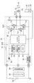
- FIG. 2 is a block diagram showing an outline of an example of the configuration of the wiper control circuit 62 of the right wiper device 16 according to the present embodiment.
- the wiper motor 20 shown in FIG. 2 is a DC motor with a brush as an example.
- the configuration of the wiper control circuit 60 of the left wiper device 14 is the same as that of the wiper control circuit 62 of the right wiper device 16, and thus detailed description thereof is omitted.
- the wiper control circuit 62 shown in FIG. 2 is a microcomputer of a drive circuit 62A that generates a voltage to be applied to the winding terminal of the wiper motor 20, and a wiper ECU 62B that controls on and off of the switching elements constituting the drive circuit 62A. 48.
- the power of the battery 80 is supplied to the microcomputer 48 via the diode 56, and the voltage of the supplied power is detected by a voltage detection circuit 50 provided between the diode 56 and the microcomputer 48. The detection result is output to the microcomputer 48.
- An electrolytic capacitor C1 is provided between the diode 56 and the microcomputer 48, with one end connected and the other end (-) grounded.
- the electrolytic capacitor C ⁇ b> 1 is a capacitor for stabilizing the power supply of the microcomputer 48.
- the electrolytic capacitor C1 protects the microcomputer 48 by storing a sudden high voltage such as a surge and discharging it to the ground region.
- the microcomputer 48 receives a command signal for instructing the rotational speed of the wiper motor 18 from the wiper switch 66 and the vehicle control circuit 64 via the signal input circuit 52.
- the command signal output from the wiper switch 66 is an analog signal
- the signal is digitized by the signal input circuit 52 and input to the microcomputer 48.
- a rotation angle sensor 44 that detects a magnetic field of the sensor magnet 70 that changes in accordance with the rotation of the output shaft 38 is connected to the microcomputer 48.
- the microcomputer 48 determines the position of the wiper blades 30 and 32 on the windshield glass 12 by calculating the rotation angle of the output shaft 38 based on the signal output from the rotation angle sensor 44.
- the microcomputer 48 refers to the rotational speed data of the wiper motor 20 defined according to the position of the wiper blades 30 and 32 stored in the memory 54, and the rotation of the wiper motor 20 determines the specified wiper blade 30. , 32 is controlled so that the number of rotations corresponds to the position of 32.
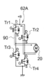
- the drive circuit 62A uses transistors Tr1, Tr2, Tr3, Tr4 which are N-type FETs (field effect transistors) as switching elements.
- the drains of the transistors Tr1 and Tr2 are connected to the battery 80 via the noise prevention coil 76, and the sources are connected to the drains of the transistors Tr3 and Tr4, respectively.
- the sources of the transistors Tr3 and Tr4 are grounded.
- the source of the transistor Tr1 and the drain of the transistor Tr3 are connected to one end of the winding of the wiper motor 18, and the source of the transistor Tr2 and the drain of the transistor Tr4 are connected to the other end of the winding of the wiper motor 18. .
- the transistors Tr2 and Tr3 when a high level signal is input to the gates of the transistors Tr2 and Tr3, the transistors Tr2 and Tr3 are turned on, and the wiper motor 20 has the wiper blades 30 and 32 viewed from the passenger compartment side, for example.
- a CCW current 74 that operates in a clockwise direction flows.
- the other when one of the transistors Tr2 and Tr3 is on-controlled, the other is controlled on and off by PWM control, whereby the voltage of the CCW current 74 can be modulated.
- a reverse connection protection circuit 58 and a noise prevention coil 76 are provided between the battery 80 as a power source and the drive circuit 62A, and an electrolytic capacitor C2 is provided in parallel with the drive circuit 62A. It has been.
- the noise prevention coil 76 is an element for suppressing noise generated by switching of the drive circuit 62A.
- the electrolytic capacitor C2 relieves noise generated from the drive circuit 62A, stores a sudden high voltage such as a surge, and discharges it to the ground region, whereby an excessive current is input to the high voltage drive circuit 62A. This is an element for preventing this.
- the reverse connection protection circuit 58 is a circuit for protecting the elements constituting the wiper control circuit 62 when the positive electrode and the negative electrode of the battery 80 are connected in reverse to the case shown in FIG.
- the reverse connection protection circuit 58 includes a so-called diode-connected FET or the like in which its drain and gate are connected.
- current sensors that detect the current values of the wiper motors 18 and 20 are provided.
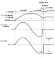
- FIG. 3 shows an example of the wiper output shaft position, the wiper blade wiping speed, and the motor output in the wiper control device 10 according to the present embodiment.
- the OPEN operation in which the wiper blades 30 and 32 move from the storage position P3 toward the upper reversal position P1 is started, and after the wiper blades 30 and 32 reach the upper reversal position P1, It is shown that the CLOSE operation that operates toward the storage position P3 is started.
- FIG. 3 shows a case where the CLOSE operation is hindered by an external force due to a snow accumulation or the like, and the wiper blades 30 and 32 are stopped at a position before the retracted position and the lower reverse position.
- the wiper blade wiping speed is rapidly decelerated due to collision with a snow puddle that is an obstacle, and the motor output increases the output to maintain the wiping speed.
- the wiper arms 26 and 28 bend.
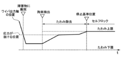
- FIG. 4A is a schematic diagram illustrating an example in which self-locking is performed when the wiper arms 26 and 28 are moved from the storage position P3 side toward the upper reversal position P1 side after executing “deflection removal”.
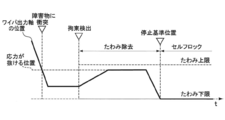
- FIG. 4B is a schematic diagram illustrating an example in which self-locking is performed when the wiper arms 26 and 28 are moved from the upper reversal position P1 side toward the storage position P3 side after executing “deflection removal”. .
- the output of the wiper motors 18 and 20 even after “collision with an obstacle” due to the deflection of the wiper arms 26 and 28.
- the shafts 36 and 38 continue to rotate for a while.
- the output shafts 36 and 38 can no longer rotate, and the output shafts 36 and 38 stop rotating.
- the time when the output shafts 36 and 38 stop rotating is referred to as “constraint detection”.
- the microcomputer 48 is obtained from the position of the wiper blades 30 and 32 obtained from the rotation angle of the output shafts 36 and 38 detected by the rotation angle sensors 42 and 44 and the rotation angle detected by the rotation angle sensors 42 and 44. Based on the rotational speed of the output shafts 36 and 38, when the wiper blades 30 and 32 are stopped at a position other than the storage position P3 or the lower inversion position P2, “constraint detection” is determined.
- the microcomputer 48 sets the “deflection upper limit” and the “deflection lower limit” shown in FIG. 4 together with “restraint detection”.
- the “deflection upper limit” and “deflection lower limit” shown in FIG. 4 are upper and lower limits of a predetermined range centering on the position when the wiper blades 30 and 32 are locked by an obstacle.
- the predetermined range is specifically determined according to the specifications of the wiper device.
- the microcomputer 48 performs control for eliminating the stress acting on the eye arm 26, 28, etc. due to the obstacle when the "constraint detection" is performed. Specifically, the supply of electric power for rotating the wiper motors 18 and 20 is stopped for a predetermined time. Since the time for stopping the power supply varies depending on the specifications of the wiper device, a specific optimum value is set for each product. As a result, the output shafts 36 and 38 are rotated in a direction in which the deflection of the wiper arms 26 and 28 is reduced. When “the position of the wiper output shaft” returns to the position where the wiper blades 30 and 32 “collision with the obstacle”, the stress acting on the wiper blades 30 and 32 and the wiper arms 26 and 28 is released. “Deflection” is completed.
- FIG. 4A shows a case where the “stress release position” at which “deflection removal” has been completed is a position where the wiper blades 30, 32, etc. are pushed up by the traveling wind.
- FIG. 4B shows a case where the “stress release position” at which “deflection removal” is completed is a position where the wiper blades 30, 32, etc. are pushed down by the traveling wind.
- the self-lock control is started.
- the output shafts 36 and 38 rotate in the direction opposite to the direction of deviation according to the amount of deviation of the "wiper output shaft position” from the “deflection upper limit” or “deflection lower limit” that is the “stop reference position”.
- electric power is supplied to the wiper motors 18 and 20.
- the microcomputer 48 controls the brake energization as shown in FIG. 5 at the time of “restraint detection” of the wiper arms 26, 28, etc. as control for eliminating the stress acting on the eyer arms 26, 28, etc. due to the obstacle. May be performed to remove the deflection.
- 5 illustrates the drive circuit 62A and the wiper motor 20 of the right wiper device 16 as an example. Since the configuration of the drive circuit 60A of the left wiper device 14 is the same as that of the drive circuit 62A of the right wiper device 16, its detailed description is omitted.
- the brake energization is performed by turning on the transistor Tr1 and the transistor Tr2 to short-circuit the terminals of the motor and energizing the current 90 generated in the motor coil in the direction indicated by the arrow.
- the transistor Tr3 and the transistor Tr4 may be turned on so that one terminal and the other terminal of the wiper motor 20 are grounded. Since the brake energization time varies depending on the specifications of the wiper device, a specific optimum value is set for each product.
- the stress due to the deflection can be eliminated, but the wiper arm 28 is repelled by the stress due to the deflection, and the wiper blade 32 moves to an unexpected position.
- the position of the wiper blade 32 after the “deflection removal” is obstructed by suppressing the rotation of the output shaft 38 of the wiper motor 20 by applying the brake as shown in FIG. It is possible to be close to the position stopped by.
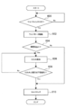
- FIG. 6 is a flowchart showing an example of a deflection removing process in the wiper control device 10 according to the present embodiment.
- step 600 it is determined whether or not the wiper switch 66 has been turned off. If the determination is affirmative, the wiper blades 30 and 32 are moved to the self-lock target position where the self-lock is executed in step 602. The wiper motors 18 and 20 are driven as described above.
- the self-lock target position is, for example, the storage position P3 or the lower inversion position P2.
- step 604 the wiping operation of the wiper blades 30 and 32 is hindered by an obstacle on the windshield glass 12 based on the rotation angle and rotation speed of the wiper motors 18 and 20, the change in the current value of the wiper motors 18 and 20, or the like. If the determination is affirmative, the procedure proceeds to step 606. If the determination is negative, the procedure proceeds to step 610.
- step 606 power supply to the wiper motors 18 and 20 is stopped, or brake energization as shown in FIG. 5 is performed to remove the deflection of the wiper arms 26 and 28 and the like.
- step 608 it is determined whether or not the position of the wiper blades 30 and 32 after the “deflection removal” exceeds the “deflection upper limit” or the “deflection lower limit”. If the determination in step 608 is affirmative, the position of the wiper blades 30 and 32 after “deflection removal” is set to the “stop reference position”. If the determination in step 608 is negative, the procedure returns to step 606 and “deflection removal” is continued.
- the wiper motors 18 and 20 are controlled to remove the deflection, thereby causing the obstacle.
- Self-locking can be performed by eliminating the influence of the deflection of the wiper arms 26 and 28.
- the stopped state of the wiper arms 26 and 28 can be maintained near the position where the wiper arms 26 and 28 are stopped by an obstacle.
- the deflection removal control to the wiper motors 18 and 20 is continued.
- the position of the wiper blade after “deflection removal” is set to the “stop reference position”. And the self-lock is executed at the “stop reference position”.
- the wiper motors 18 and 20 are not forcibly driven, so that an excessive load can be prevented from being applied to the wiper motors 18 and 20.
- the wiper control device 10 may be used for a wiper device having a link mechanism in addition to the tandem wiper device 100 having no link mechanism.
Landscapes
- Engineering & Computer Science (AREA)
- Mechanical Engineering (AREA)
- Control Of Direct Current Motors (AREA)
- Control Of Electric Motors In General (AREA)
- Stopping Of Electric Motors (AREA)
Abstract
ワイパ制御回路は、ワイパブレードが格納位置の手前で停止された場合に、ワイパモータを回転させる電力供給を停止する。ワイパ制御回路は、回転角度センサによって検出されたワイパモータを回転させる電力を供給停止した前後での出力軸の回転角度の変化量が所定範囲に到達した場合には、電力供給停止後の状態で出力軸の回転を防止するセルフロックを実行する。
Description
本発明は、ワイパ制御装置に関する。
1つのワイパモータで運転席側のワイパブレードと助手席側のワイパブレードとを動作させるワイパ装置では、ワイパモータの回転力をワイパアームに伝達するリンク機構を有している。かかるリンク機構は、ワイパブレード又はワイパアームに車両の走行風等による外力が作用した場合に、ワイパブレードが当該外力によって意に反した位置に移動することを抑制する機能も有している。
しかしながら、運転席側のワイパブレードと、助手席側のワイパブレードとを、独立した別個のモータで動作させるワイパ装置は、ワイパアームとワイパモータとの間にリンク機構を有しない場合が多い。かかるワイパ装置では、ワイパブレードが車両の走行風等による外力を受けると、ワイパブレードが意に反した位置に移動する蓋然性が、リンク機構を有するワイパ装置よりも高い。
特表2011-512285号公報、特許第4691165号公報、特許第5535738号公報には、下反転位置等の停止基準位置で停止しているワイパブレードが外力の作用によって移動した場合に、外力を相殺するようにワイパモータを駆動させて、移動したワイパブレードを下反転位置等の元の位置に戻すセルフクロックを行うワイパ装置が開示されている。
しかしながら、特表2011-512285号公報、特許第4691165号公報、特許第5535738号公報に開示された技術は、ウィンドシールドガラス上に雪溜まり等の障害物が存在したことにより、ワイパブレードが下反転位置又は格納位置等の所定の位置に到達できない場合に、ワイパモータに負荷が掛かるおそれがあった。
図7は、セルフロックが可能なワイパ装置における、ワイパブレード位置、ワイパブレード払拭速度、モータ出力の一例を示している。図7では、ワイパブレードが格納位置から上反転位置に向かって動作するOPEN作動を開始し、ワイパブレードが上反転位置に到達した後は、上反転位置から格納位置に向かって動作するCLOSE作動が開始されることが示されている。ワイパブレード払拭速度及びモータ出力は、OPEN作動の途中で極大となり、上反転位置で0になった後、CLOSE作動の途中でOPEN作動の場合とは逆方向で極大となる。
また、図7は、CLOSE作動が雪溜まり等によって阻害され、ワイパブレードが格納位置又は下反転位置よりも手前の位置で停止した場合の一例を示している。ワイパブレード払拭速度は、雪溜まりの影響で急減速され、モータ出力は払拭速度を維持しようと出力を上昇させる。かかる場合に、セルフロックを行うワイパ装置では、下反転位置の手前で停止したワイパブレードの位置を停止基準位置としてセルフクロックの制御を実行する。
しかしながら、図7に示した停止基準位置でワイパブレードが停止している状態では、雪溜まり等の障害物により、ワイパアームをたわませる応力がワイパ装置の出力軸に作用している。かかる状態でセルフロックを実行すると、ワイパアームをたわませる応力に抗してワイパモータを駆動させ続けることになる。その結果、ワイパモータ及びモータの駆動回路等が過熱状態になり、過熱防止のためのフェールセーフによりワイパモータの作動が緊急停止されるおそれがあった。
本発明の実施形態は、上記事実を考慮してなされたもので、ウィンドシールドガラス上の障害物によるワイパアームのたわみの影響を排除してセルフロックを実行するワイパ制御装置を提供することを目的とする。
前記課題を解決するために、本開示は、ウィンドシールドガラス上でワイパブレードを往復払拭させるワイパモータの出力軸の回転角度を検出する回転角度検出部と、前記回転角度検出部で検出された回転角度に基づいて、予め定められた位置以外の位置で前記ワイパブレードが停止されたことを判定した際に、前記ワイパモータを回転させる電力供給を所定時間停止し、前記ワイパブレードが停止された際に前記回転角度検出部で検出された回転角度と、前記ワイパモータに対する電力供給を所定時間停止した後に前記回転角度検出部で検出された回転角度との差が所定値に到達した場合にセルフロックを行うための通電制御を行う制御部と、を含んでいる。
このワイパ制御装置によれば、ウィンドシールドガラス上の障害物等によってワイパブレードの払拭動作が停止された場合に、ワイパモータへの通電を停止することにより、障害物等の干渉によるワイパアームのたわみを除去する。そして、通電停止の前後でのワイパモータの出力軸の回転角度の変化量が所定値に到達した場合には、セルフロックを実行する。その結果、ウィンドシールドガラス上の障害物によるワイパアームのたわみの影響を排除してセルフロックを実行することができる。
また、本開示は、前記制御部は、前記回転角度検出部で検出された回転角度から得られるワイパブレードの位置、及び前記回転角度検出部で検出された回転角度から得られる前記出力軸の回転速度に基づいて、前記予め定められた位置以外の位置で前記ワイパブレードが停止されたかを判定する。
このワイパ制御装置によれば、出力軸の回転角度から算出されるワイパブレードの位置が予め定められた位置以外の位置であって、かつ出力軸の回転速度が減速された場合に、ワイパブレードが障害物等によって所定位置の手前で停止したと判定できる。
また、本開示は、前記制御部は、前記ワイパモータを回転させる電力供給を所定時間停止する際に、前記ワイパモータの端子を短絡させることにより前記出力軸のブレーキ制御を行う。
このワイパ制御装置によれば、回転時には互いに異なる極性の電圧が印加されるワイパモータの各端子に同一極性の電圧を印加することによって、ワイパモータの出力軸の回転を制動する。かかる制動により、ワイパアームのたわみによって、ワイパブレードが弾かれる現象を防止できる。
また、本開示は、前記セルフロックは、前記ワイパブレードの停止状態を維持させるために、前記回転角度検出部で検出された回転角度が変化した際に、該変化が相殺されるように前記出力軸を回転させる
このワイパ制御装置によれば、回転角度検出部で検出されたワイパモータの出力軸の回転角度が変化した場合に、当該変化が相殺されるように出力軸を回転させる制御により、外力による出力軸の回転を抑制する。かかる制御を行うことにより、出力軸を機械的に拘束する構成を別途必要とせずに、外力による出力軸の回転を防止できる。
図1は、本実施形態に係るワイパ制御装置10を含むワイパ装置100の構成を示す概略図である。ワイパ装置100は、一例として、右ハンドル車両のウィンドシールドガラス12の下部の左(助手席側)に左ワイパ装置14、車両のウィンドシールドガラス12の下部の右(運転席側)に右ワイパ装置16を各々備えたタンデム式のワイパ装置である。なお、本実施形態における左右は、車室内から見ての左右である。
左ワイパ装置14及び右ワイパ装置16は、ワイパモータ18、20、減速機構22、24、ワイパアーム26、28及びワイパブレード30、32を各々備えている。ワイパモータ18、20は、ウィンドシールドガラス12の左下方及び右下方の各々に設けられている。
左ワイパ装置14及び右ワイパ装置16は、ワイパモータ18、20の正逆回転が減速機構22、24で各々減速され、減速機構22、24によって減速された正逆回転で出力軸36、38が各々回転する。さらに、出力軸36、38の正逆回転の回転力がワイパアーム26、28に各々作用することによりワイパアーム26、28が格納位置P3から下反転位置P2に移動し、下反転位置P2と上反転位置P1との間を往復動作する。かかるワイパアーム26、28の動作により、ワイパアーム26、28の先端に各々設けられたワイパブレード30、32がウィンドシールドガラス12表面の下反転位置P2から上反転位置P1の間を払拭する。なお、減速機構22、24は、例えばウォームギア等で構成され、ワイパモータ18、20の回転を、ワイパブレード30、32によるウィンドシールドガラス12表面の払拭に適した回転速度に各々減速し、当該回転速度で出力軸36、38を各々回転させる。なお、上反転位置P1、下反転位置P2及び格納位置P3は、各々ウィンドシールドガラス12上の所定位置であり、ワイパ装置によっては、下反転位置P2が格納位置P3を兼ねる場合もある。
本実施形態に係るワイパモータ18、20は、上述のように、ウォームギアで構成された減速機構22、24を各々有しているので、出力軸36、38の回転速度及び回転角度は、ワイパモータ18、20本体の回転速度及び回転角度と同一ではない。しかしながら、本実施形態では、ワイパモータ18、20と減速機構22、24は各々一体不可分に構成されているので、以下、出力軸36、38の回転速度及び回転角度を、ワイパモータ18、20の各々の回転速度及び回転角度とみなす。
ワイパモータ18、20には、ワイパモータ18、20の回転を制御するためのワイパ制御回路60、62が各々接続されている。本実施形態に係るワイパ制御回路60は駆動回路60A及びワイパECU60Bを、ワイパ制御回路62は、駆動回路62A及びワイパECU62Bを、各々含む。
ワイパECU60Bには、ワイパモータ18の出力軸36の回転速度及び回転角度を各々検知する回転角度センサ42が接続されている。ワイパECU62Bには、ワイパモータ20の出力軸38の回転速度及び回転角度を各々検知する回転角度センサ44が接続されている。ワイパECU60B、62Bは、回転角度センサ42、44からの信号に基づいて、ウィンドシールドガラス12上でのワイパブレード30、32の位置を各々算出する。また、ワイパECU60B、62Bは、算出したワイパブレード30、32の位置に応じて出力軸36、38の回転速度が変化するように駆動回路60A、62Aを各々制御する。なお、回転角度センサ42、44は、ワイパモータ18、20の減速機構22、24内に各々設けられ、出力軸36、38に連動して回転する励磁コイル又はマグネットの磁界(磁力)を電流に変換して検出する。また、セルフロックを実行する場合には、ワイパブレードが停止基準位置から逸脱したか否かを回転角度センサ42、44によって検出する。停止基準位置は、ワイパ装置100の仕様によって異なり、後述するようにワイパブレード30、32に外力が作用した場合に変化するが、本実施形態では、通常は格納位置P3である。
駆動回路60A、62Aは、ワイパモータ18、20を各々作動させるための電圧(電流)をPWM(Pulse Width Modulation)制御によって生成してワイパモータ18、20に各々供給する。駆動回路60A、62Aは、スイッチング素子にMOSFET(金属酸化物半導体電界効果トランジスタ)を使用した回路を含み、駆動回路60AはワイパECU60Bの、駆動回路62AはワイパECU62Bの、各々の制御によって、所定のデューティ比の電圧を出力する。
ワイパECU60BとワイパECU62Bとは、例えば、LIN(Local Interconnect Network)等のプロトコルを用いた通信で連携させることにより、左ワイパ装置14及び右ワイパ装置16の動作を同期させている。また、ワイパ制御回路62のワイパECU62Bには、車両制御回路64を介して、ワイパスイッチ66が接続されている。
ワイパスイッチ66は、車両のバッテリからワイパモータ18、20に供給される電力をオン又はオフするスイッチである。ワイパスイッチ66は、ワイパブレード30、32を、低速で動作させる低速作動モード選択位置、高速で動作させる高速作動モード選択位置、一定周期で間欠的に動作させる間欠作動モード選択位置、停止モード選択位置に切替可能である。また、各モードの選択位置に応じてワイパモータ18、20を回転させるための指令信号を車両制御回路64を介してワイパECU62Bに出力する。また、ワイパECU62Bに入力された指令信号は、前述のLIN等のプロトコルを用いた通信によってワイパECU60Bにも入力される。
ワイパスイッチ66から各モードの選択位置に応じて出力された信号がワイパECU60B、62Bに入力されると、ワイパECU60B、62Bがワイパスイッチ66からの出力信号に対応する制御を行う。具体的には、ワイパECU60B、62Bは、ワイパスイッチ66からの指令信号に基づいて出力軸36、38の回転速度を算出する。さらにワイパECU60B、62Bは、算出した回転速度で出力軸36、38が回転するように駆動回路60A、62Aを制御する。
図2は、本実施形態に係る右ワイパ装置16のワイパ制御回路62の構成の一例の概略を示すブロック図である。また、図2示したワイパモータ20は、一例として、ブラシ付きDCモータである。なお、左ワイパ装置14のワイパ制御回路60の構成は、右ワイパ装置16のワイパ制御回路62と同様なので、その詳細な説明は省略する。
図2に示したワイパ制御回路62は、ワイパモータ20の巻線の端子に印加する電圧を生成する駆動回路62Aと、駆動回路62Aを構成するスイッチング素子のオン及びオフを制御するワイパECU62Bのマイクロコンピュータ48とを含んでいる。マイクロコンピュータ48には、ダイオード56を介してバッテリ80の電力が供給されると共に、供給される電力の電圧は、ダイオード56とマイクロコンピュータ48との間に設けられた電圧検出回路50によって検知され、検知結果はマイクロコンピュータ48に出力される。また、ダイオード56とマイクロコンピュータ48との間に一端が接続され、他端(-)が接地された電解コンデンサC1が設けられている。電解コンデンサC1は、マイクロコンピュータ48の電源を安定化するためのコンデンサである。電解コンデンサC1は、例えば、サージ等の突発的な高電圧を蓄え、接地領域に放電することにより、マイクロコンピュータ48を保護する。
マイクロコンピュータ48には信号入力回路52を介してワイパスイッチ66及び車両制御回路64からワイパモータ18の回転速度を指示するための指令信号が入力される。ワイパスイッチ66から出力された指令信号はアナログ信号の場合には、当該信号は信号入力回路52においてデジタル化されてマイクロコンピュータ48に入力される。
また、マイクロコンピュータ48には、出力軸38の回転に応じて変化するセンサマグネット70の磁界を検知する回転角度センサ44が接続されている。マイクロコンピュータ48は、回転角度センサ44が出力した信号に基づいて、出力軸38の回転角度を算出することにより、ワイパブレード30、32のウィンドシールドガラス12上での位置を特定する。
さらに、マイクロコンピュータ48は、メモリ54に記憶されているワイパブレード30、32の位置に応じて規定されたワイパモータ20の回転速度のデータを参照して、ワイパモータ20の回転が、特定したワイパブレード30、32の位置に応じた回転数になるように駆動回路62Aを制御する。
駆動回路62Aは、図2に示すように、スイッチング素子にN型のFET(電界効果トランジスタ)であるトランジスタTr1、Tr2、Tr3、Tr4を用いている。トランジスタTr1及びトランジスタTr2は、ドレインがノイズ防止コイル76を介してバッテリ80に各々接続されており、ソースがトランジスタTr3及びトランジスタTr4のドレインに各々接続されている。また、トランジスタTr3及びトランジスタTr4のソースは接地されている。
また、トランジスタTr1のソース及びトランジスタTr3のドレインは、ワイパモータ18の巻線の一端に接続されており、トランジスタTr2のソース及びトランジスタTr4のドレインは、ワイパモータ18の巻線の他端に接続されている。
トランジスタTr1及びトランジスタTr4の各々のゲートにハイレベル信号が入力されることにより、トランジスタTr1及びトランジスタTr4がオンになり、ワイパモータ20には例えばワイパブレード30、32を車室側から見て時計回りに動作させるCW電流72が流れる。さらに、トランジスタTr1及びトランジスタTr4の一方をオン制御しているとき、他方をPWM制御により、小刻みにオンオフ制御することにより、CW電流72の電圧を変調できる。
また、トランジスタTr2及びトランジスタTr3の各々のゲートにハイレベル信号が入力されることにより、トランジスタTr2及びトランジスタTr3がオンになり、ワイパモータ20には例えばワイパブレード30、32を車室側から見て反時計回りに動作させるCCW電流74が流れる。さらに、トランジスタTr2及びトランジスタTr3の一方をオン制御しているとき、他方をPWM制御により、小刻みにオンオフ制御することにより、CCW電流74の電圧を変調できる。
本実施形態では、電源であるバッテリ80と駆動回路62Aとの間には逆接続保護回路58及びノイズ防止コイル76が設けられると共に、駆動回路62Aに対して並列になるように電解コンデンサC2が設けられている。ノイズ防止コイル76は、駆動回路62Aのスイッチングによって発生するノイズを抑制するための素子である。
電解コンデンサC2は、駆動回路62Aから生じるノイズを緩和すると共に、サージ等の突発的な高電圧を蓄え、接地領域に放電することにより、当該高電圧の駆動回路62Aに過大な電流が入力されるのを防止するための素子である。
逆接続保護回路58は、バッテリ80の正極と負極が図2に示した場合とは逆に接続された場合に、ワイパ制御回路62を構成する素子を保護するための回路である。逆接続保護回路58は、一例として、自身のドレインとゲートを接続した、いわゆるダイオード接続されたFET等で構成される。また、図2に図示していないが、本実施形態では、ワイパモータ18、20の電流値を各々検出する電流センサが設けられる。
以下、本実施形態に係るワイパ制御装置10の作用及び効果について説明する。図3は、本実施形態に係るワイパ制御装置10における、ワイパ出力軸位置、ワイパブレード払拭速度、モータ出力の一例を示している。図3では、ワイパブレード30、32が格納位置P3から上反転位置P1に向かって動作するOPEN作動を開始し、ワイパブレード30、32が上反転位置P1に到達した後は、上反転位置P1から格納位置P3に向かって動作するCLOSE作動が開始されることが示されている。
また、図3では、CLOSE作動が雪溜まり等による外力によって阻害され、ワイパブレード30、32が格納位置及び下反転位置よりも手前の位置で停止した場合を示している。ワイパブレード払拭速度は、障害物である雪溜まりに衝突したことで急減速され、モータ出力は払拭速度を維持しようと出力を上昇させる。しかしながら、ワイパブレード30、32は「障害物に衝突」した状態なので、ワイパアーム26、28はたわむ。ワイパアーム26、28のたわみが大きくなると、出力軸36、38に作用する抵抗も大きくなり、当該抵抗により出力軸36、38の回転が停止された時点を、図3に示した「拘束検出」とする。
本実施形態では、「拘束検出」の場合には、図3に示した「たわみ除去」を行って、ワイパアーム26、28等に作用している応力を解消した後にセルフロックを実行する。「たわみ除去」では、ワイパモータ18、20を回転させる電力の供給が停止される。
図4Aは「たわみ除去」を実行した後、ワイパアーム26、28が格納位置P3側から上反転位置P1側に向かって移動した場合に、セルフロックを実行した場合の一例を示した概略図である。図4Bは「たわみ除去」を実行した後、ワイパアーム26、28が上反転位置P1側から格納位置P3側に向かって移動した場合に、セルフロックを実行した場合の一例を示した概略図である。
障害物である雪溜まり等によってワイパブレード30、32及びワイパアーム26、28の動きが阻止されても、ワイパアーム26、28がたわむことにより、「障害物に衝突」後も、ワイパモータ18、20の出力軸36、38は回転をしばらく継続する。ワイパアーム26、28のたわみが限界に達すると、出力軸36、38はそれ以上回転できなくなり、出力軸36、38は回転を停止する。本実施形態では、出力軸36、38が回転を停止した時点を「拘束検出」とする。マイクロコンピュータ48は、回転角度センサ42、44で検出された出力軸36、38の回転角度から得られるワイパブレード30、32の位置、及び回転角度センサ42、44で検出された回転角度から得られる出力軸36、38の回転速度に基づいて、格納位置P3または下反転位置P2以外の位置でワイパブレード30、32が停止された場合に、「拘束検出」を判定する。
「拘束検出」と共にマイクロコンピュータ48は、図4に示した、「たわみ上限」及び「たわみ下限」を設定する。図4に示した、「たわみ上限」及び「たわみ下限」は、障害物でワイパブレード30、32がロックされた際の位置を中心とした所定の範囲の上限及び下限である。所定の範囲は、ワイパ装置の仕様等に応じて具体的に決定する。
また、マイクロコンピュータ48は、「拘束検出」をした時点で、障害物によりアイパアーム26、28等に作用している応力を解消する制御を行う。具体的には、ワイパモータ18、20を回転させる電力の供給を所定時間停止する。電力供給を停止する時間は、ワイパ装置の仕様等によって異なるので、製品毎に具体的な最適値を設定する。その結果、出力軸36、38は、ワイパアーム26、28のたわみが緩和される方向に回転される。「ワイパ出力軸の位置」が、ワイパブレード30、32が「障害物に衝突」した際の位置に戻った場合に、ワイパブレード30、32及びワイパアーム26、28に作用していた応力は抜け、「たわみ除去」が完了する。
しかしながら、「たわみ除去」後のワイパモータ18、20には電力が供給されていないので、走行風に係る外力により、ワイパブレード30、32の位置が「たわみ除去」が完了した位置から移動する場合がある。図4Aは、「たわみ除去」が完了した「応力が抜ける位置」が、走行風によりワイパブレード30、32等を押し上げる位置の場合である。図4Bは、「たわみ除去」が完了した「応力が抜ける位置」が、走行風によりワイパブレード30、32等を押し下げる位置の場合である。
本実施形態では、「ワイパ出力軸の位置」が、「たわみ上限」または「たわみ下限」に到達した場合に、セルフロックの制御を開始する。セルフロックでは、「停止基準位置」である「たわみ上限」または「たわみ下限」から「ワイパ出力軸の位置」がずれた量に応じて、ずれた方向と反対側に出力軸36、38が回転するように、ワイパモータ18、20へ電力を供給する。
また、マイクロコンピュータ48は、障害物によりアイパアーム26、28等に作用している応力を解消する制御として、ワイパアーム26、28等の「拘束検出」の際に、図5に示したようなブレーキ通電を実行して、当該たわみを除去してもよい。なお、図5では、右ワイパ装置16の駆動回路62A及びワイパモータ20を例示して説明している。左ワイパ装置14の駆動回路60Aの構成は、右ワイパ装置16の駆動回路62Aと同様なので、その詳細な説明は省略する。
ブレーキ通電は、図5に一例を示したように、トランジスタTr1及びトランジスタTr2を各々オンにしてモータの端子間を短絡させ、モータのコイルに発生した電流90を矢印で示した方向に通電させる。ワイパモータ20の一方の端子と他方の端子とに正電荷の電圧が印加して、一方の端子と他方の端子とを短絡させることにより、ワイパモータ20の出力軸38の回転は抑制される。なお、ブレーキ通電は、トランジスタTr3及びトランジスタTr4を各々オンにして、ワイパモータ20の一方の端子と他方の端子とが接地されるようにしてもよい。ブレーキ通電を行う時間は、ワイパ装置の仕様等によって異なるので、製品毎に具体的な最適値を設定する。
ブレーキ通電を行わずに、ワイパモータ20への通電を解除することによっても、たわみによる応力は解消できるが、たわみによる応力によってワイパアーム28が弾かれ、ワイパブレード32が意に反した位置まで移動する場合がある。かかる場合には、本実施形態では、図5に示したようなブレーキ通電によって、ワイパモータ20の出力軸38の回転を抑制することにより、「たわみ除去」後のワイパブレード32の位置を、障害物によって停止させられた位置の近くとすることが可能になる。
図6は、本実施形態にかかるワイパ制御装置10におけるたわみ除去処理の一例を示したフローチャートである。ステップ600では、ワイパスイッチ66がオフになったか否かを判定し、肯定判定の場合には、ステップ602でワイパブレード30、32をセルフロックが実行される位置であるセルフロック対象位置まで移動させるようにワイパモータ18、20を駆動させる。セルフロック対象位置は、一例として、格納位置P3又は下反転位置P2である。
ステップ604では、ワイパモータ18、20の回転角度及び回転速度、又はワイパモータ18、20の電流値の変化等に基づいて、ワイパブレード30、32がウィンドシールドガラス12上の障害物によって払拭動作が妨げられたか否かを判定し、肯定判定の場合には手順をステップ606に移行させ、否定判定の場合には手順をステップ610に移行させる。
ステップ606では、ワイパモータ18、20への電力供給を停止するか、図5に示したようなブレーキ通電を行って、ワイパアーム26、28等のたわみを除去する。そして、ステップ608では、「たわみ除去」後のワイパブレード30、32の位置が「たわみ上限」又は「たわみ下限」を超えているか否かを判定する。ステップ608で肯定判定の場合には、「たわみ除去」後のワイパブレード30、32の位置を「停止基準位置」とし、ステップ610でセルフロックを実行して処理を終了する。ステップ608で否定判定の場合には手順をステップ606に戻し、「たわみ除去」を継続する。
以上説明したように、本実施形態では、ワイパブレード30、32の動作がウィンドシールドガラス12上の障害物によって阻害された場合に、ワイパモータ18、20にたわみ除去制御を行うことにより、障害物によるワイパアーム26、28のたわみの影響を排除してセルフロックを実行することができる。その結果、障害物によりワイパアーム26、28が停止した位置近傍にてワイパアーム26、28の停止状態を維持することができる。
また、本実施形態では、「たわみ除去」前と除去後のワイパブレード30、32の移動量が所定の範囲以内であれば、ワイパモータ18、20へのたわみ除去制御を継続する。
さらに、本実施形態では、「たわみ除去」前と除去後のワイパブレード30、32の移動量が所定の範囲を超えた場合には、「たわみ除去」後のワイパブレードの位置を「停止基準位置」とし、当該「停止基準位置」でセルフロックを実行する。障害物等による応力の影響が大きい場合には、無理にワイパモータ18、20を駆動させないため、ワイパモータ18、20に過度な負荷がかかることを防止できる。
なお、本実施形態に係るワイパ制御装置10は、リンク機構を有しないタンデム式ワイパ装置100以外にも、リンク機構を有するワイパ装置に用いてもよい。
また、本発明は、上記に限定されるものでなく、上記以外にも、その主旨を逸脱しない範囲内において種々変形して実施可能であることは勿論である。
2016年2月18日に出願された日本国特許出願2016-029152号の開示は、その全体が参照により本明細書に取り込まれる。
Claims (4)
- ウィンドシールドガラス上でワイパブレードを往復払拭させるワイパモータの出力軸の回転角度を検出する回転角度検出部と、
前記回転角度検出部で検出された回転角度に基づいて、予め定められた位置以外の位置で前記ワイパブレードが停止されたことを判定した際に、前記ワイパモータを回転させる電力供給を所定時間停止し、前記ワイパブレードが停止された際に前記回転角度検出部で検出された回転角度と、前記ワイパモータに対する電力供給を所定時間停止した後に前記回転角度検出部で検出された回転角度との差が所定値に到達した場合にセルフロックを行うための通電制御を行う制御部と、
を含むワイパ制御装置。 - 前記制御部は、前記回転角度検出部で検出された回転角度から得られるワイパブレードの位置、及び前記回転角度検出部で検出された回転角度から得られる前記出力軸の回転速度に基づいて、前記予め定められた位置以外の位置で前記ワイパブレードが停止されたかを判定する請求項1記載のワイパ制御装置。
- 前記制御部は、前記ワイパモータを回転させる電力供給を所定時間停止する際に、前記ワイパモータの端子を短絡させることにより前記出力軸のブレーキ制御を行う請求項1または2に記載のワイパ制御装置。
- 前記セルフロックは、前記ワイパブレードの停止状態を維持させるために、前記回転角度検出部で検出された回転角度が変化した際に、該変化が相殺されるように前記出力軸を回転させる請求項1~3のいずれか1項記載のワイパ制御装置。
Priority Applications (3)
| Application Number | Priority Date | Filing Date | Title |
|---|---|---|---|
| US15/998,581 US10829090B2 (en) | 2016-02-18 | 2017-02-14 | Wiper control device |
| DE112017000896.4T DE112017000896T5 (de) | 2016-02-18 | 2017-02-14 | Wischersteuerungseinrichtung |
| CN201780011951.0A CN109070843B (zh) | 2016-02-18 | 2017-02-14 | 雨刮器控制装置 |
Applications Claiming Priority (2)
| Application Number | Priority Date | Filing Date | Title |
|---|---|---|---|
| JP2016029152A JP6583042B2 (ja) | 2016-02-18 | 2016-02-18 | ワイパ制御装置 |
| JP2016-029152 | 2016-02-18 |
Publications (1)
| Publication Number | Publication Date |
|---|---|
| WO2017141920A1 true WO2017141920A1 (ja) | 2017-08-24 |
Family
ID=59625149
Family Applications (1)
| Application Number | Title | Priority Date | Filing Date |
|---|---|---|---|
| PCT/JP2017/005374 Ceased WO2017141920A1 (ja) | 2016-02-18 | 2017-02-14 | ワイパ制御装置 |
Country Status (5)
| Country | Link |
|---|---|
| US (1) | US10829090B2 (ja) |
| JP (1) | JP6583042B2 (ja) |
| CN (1) | CN109070843B (ja) |
| DE (1) | DE112017000896T5 (ja) |
| WO (1) | WO2017141920A1 (ja) |
Families Citing this family (7)
| Publication number | Priority date | Publication date | Assignee | Title |
|---|---|---|---|---|
| US11420594B2 (en) | 2017-08-28 | 2022-08-23 | Rosemount Aerospace Inc. | Configurable variable sweep variable speed wiper system |
| JP6962209B2 (ja) * | 2018-01-18 | 2021-11-05 | 株式会社デンソー | ワイパ制御装置 |
| CN111361528A (zh) * | 2020-04-27 | 2020-07-03 | 浙江宏博汽配有限公司 | 一种智能雨刷电机的控制系统 |
| JP7435912B2 (ja) * | 2021-05-14 | 2024-02-21 | 株式会社デンソー | 車両用ワイパ装置及び車両用ワイパ装置の制御方法 |
| CN114523935A (zh) * | 2022-01-26 | 2022-05-24 | 贵阳万江航空机电有限公司 | 一种汽车雨刮片不同停靠位置交替功能的实现方法 |
| US12545393B2 (en) * | 2023-04-25 | 2026-02-10 | Rosemount Aerospace Inc. | Systems for precise control of wiper |
| CN119142296B (zh) * | 2024-09-30 | 2026-03-10 | 长城汽车股份有限公司 | 一种控制雨刮器的方法、装置、车辆和存储介质 |
Citations (3)
| Publication number | Priority date | Publication date | Assignee | Title |
|---|---|---|---|---|
| JP4691165B2 (ja) * | 2005-10-24 | 2011-06-01 | ローベルト ボツシユ ゲゼルシヤフト ミツト ベシユレンクテル ハフツング | ワイパー装置 |
| JP2011218997A (ja) * | 2010-04-12 | 2011-11-04 | Mitsuba Corp | ワイパ制御装置及びワイパ装置制御方法 |
| JP2013052826A (ja) * | 2011-09-06 | 2013-03-21 | Mitsuba Corp | ワイパ制御装置 |
Family Cites Families (11)
| Publication number | Priority date | Publication date | Assignee | Title |
|---|---|---|---|---|
| JPS5535738A (en) | 1978-09-01 | 1980-03-12 | Seiko Epson Corp | Paper feeder |
| JPH02158446A (ja) * | 1988-12-12 | 1990-06-18 | Asmo Co Ltd | ワイパ制御装置 |
| JP4425306B2 (ja) * | 2007-11-13 | 2010-03-03 | 株式会社ミツバ | 対向払拭型ワイパ装置 |
| DE102008000298A1 (de) * | 2008-02-14 | 2009-08-20 | Robert Bosch Gmbh | Elektronische Selbsthemmung für eine Scheibenwischvorrichtung |
| CN103619661B (zh) | 2011-07-06 | 2016-01-27 | 株式会社美姿把 | 电动机控制装置 |
| CN202320213U (zh) * | 2011-11-15 | 2012-07-11 | 株洲联诚集团有限责任公司 | 电力机车雨刮自动控制器 |
| US9031390B2 (en) * | 2012-03-26 | 2015-05-12 | Asmo Co., Ltd. | Wiper device |
| US9061657B2 (en) * | 2012-07-10 | 2015-06-23 | Asmo Co., Ltd. | Wiper device |
| JP6334856B2 (ja) | 2013-07-04 | 2018-05-30 | 株式会社ミツバ | モータ制御方法及びモータ制御装置 |
| JP2016029152A (ja) | 2014-07-24 | 2016-03-03 | 日本合成化学工業株式会社 | アニオン硬化性化合物用硬化剤、硬化性組成物、及び硬化物 |
| JP6528398B2 (ja) * | 2014-12-12 | 2019-06-12 | 株式会社デンソー | ワイパ制御装置 |
-
2016
- 2016-02-18 JP JP2016029152A patent/JP6583042B2/ja active Active
-
2017
- 2017-02-14 DE DE112017000896.4T patent/DE112017000896T5/de active Granted
- 2017-02-14 CN CN201780011951.0A patent/CN109070843B/zh active Active
- 2017-02-14 WO PCT/JP2017/005374 patent/WO2017141920A1/ja not_active Ceased
- 2017-02-14 US US15/998,581 patent/US10829090B2/en active Active
Patent Citations (3)
| Publication number | Priority date | Publication date | Assignee | Title |
|---|---|---|---|---|
| JP4691165B2 (ja) * | 2005-10-24 | 2011-06-01 | ローベルト ボツシユ ゲゼルシヤフト ミツト ベシユレンクテル ハフツング | ワイパー装置 |
| JP2011218997A (ja) * | 2010-04-12 | 2011-11-04 | Mitsuba Corp | ワイパ制御装置及びワイパ装置制御方法 |
| JP2013052826A (ja) * | 2011-09-06 | 2013-03-21 | Mitsuba Corp | ワイパ制御装置 |
Also Published As
| Publication number | Publication date |
|---|---|
| US20190263359A1 (en) | 2019-08-29 |
| JP6583042B2 (ja) | 2019-10-02 |
| US10829090B2 (en) | 2020-11-10 |
| CN109070843B (zh) | 2022-01-11 |
| DE112017000896T5 (de) | 2018-11-22 |
| CN109070843A (zh) | 2018-12-21 |
| JP2017144923A (ja) | 2017-08-24 |
Similar Documents
| Publication | Publication Date | Title |
|---|---|---|
| JP6583042B2 (ja) | ワイパ制御装置 | |
| CN107000693B (zh) | 雨刮器控制装置 | |
| JP5936269B2 (ja) | 車両の窓開閉制御装置 | |
| US20200079324A1 (en) | Wiper drive device | |
| US20190329736A1 (en) | Wiper control device | |
| CN108698564B (zh) | 雨刮器控制装置 | |
| JP6294138B2 (ja) | ワイパ制御装置 | |
| KR20130047666A (ko) | 윈드스크린 와이퍼 모터의 활성화 방법 | |
| CN109155603B (zh) | 电动机控制装置及电动机控制程序 | |
| JP6809283B2 (ja) | ワイパ装置 | |
| JP7272219B2 (ja) | 開閉体駆動装置およびその制御方法 | |
| JP2008296790A (ja) | ワイパー装置 | |
| JP6454132B2 (ja) | ワイパシステム | |
| JP6593215B2 (ja) | ワイパ制御装置 | |
| US11661034B2 (en) | Wiper control device | |
| JP6798272B2 (ja) | ワイパ装置 | |
| EP3624329B1 (en) | Brushless motor, method for controlling the same and method for controlling wiper device | |
| JP7014002B2 (ja) | ワイパ装置及びワイパ装置の制御方法 | |
| JP2018090129A (ja) | ワイパ装置 | |
| JP2018131063A (ja) | ワイパ装置 | |
| JP2018086959A (ja) | ワイパ装置 | |
| JP2018127166A (ja) | ワイパ装置 |
Legal Events
| Date | Code | Title | Description |
|---|---|---|---|
| 121 | Ep: the epo has been informed by wipo that ep was designated in this application |
Ref document number: 17753177 Country of ref document: EP Kind code of ref document: A1 |
|
| 122 | Ep: pct application non-entry in european phase |
Ref document number: 17753177 Country of ref document: EP Kind code of ref document: A1 |