WO2017141917A1 - バランサ装置 - Google Patents
バランサ装置 Download PDFInfo
- Publication number
- WO2017141917A1 WO2017141917A1 PCT/JP2017/005368 JP2017005368W WO2017141917A1 WO 2017141917 A1 WO2017141917 A1 WO 2017141917A1 JP 2017005368 W JP2017005368 W JP 2017005368W WO 2017141917 A1 WO2017141917 A1 WO 2017141917A1
- Authority
- WO
- WIPO (PCT)
- Prior art keywords
- balancer
- boss
- housing
- oil pump
- balancer device
- Prior art date
- Legal status (The legal status is an assumption and is not a legal conclusion. Google has not performed a legal analysis and makes no representation as to the accuracy of the status listed.)
- Ceased
Links
Images





Classifications
-
- F—MECHANICAL ENGINEERING; LIGHTING; HEATING; WEAPONS; BLASTING
- F16—ENGINEERING ELEMENTS AND UNITS; GENERAL MEASURES FOR PRODUCING AND MAINTAINING EFFECTIVE FUNCTIONING OF MACHINES OR INSTALLATIONS; THERMAL INSULATION IN GENERAL
- F16F—SPRINGS; SHOCK-ABSORBERS; MEANS FOR DAMPING VIBRATION
- F16F15/00—Suppression of vibrations in systems; Means or arrangements for avoiding or reducing out-of-balance forces, e.g. due to motion
- F16F15/22—Compensation of inertia forces
- F16F15/26—Compensation of inertia forces of crankshaft systems using solid masses, other than the ordinary pistons, moving with the system, i.e. masses connected through a kinematic mechanism or gear system
- F16F15/264—Rotating balancer shafts
-
- F—MECHANICAL ENGINEERING; LIGHTING; HEATING; WEAPONS; BLASTING
- F01—MACHINES OR ENGINES IN GENERAL; ENGINE PLANTS IN GENERAL; STEAM ENGINES
- F01M—LUBRICATING OF MACHINES OR ENGINES IN GENERAL; LUBRICATING INTERNAL COMBUSTION ENGINES; CRANKCASE VENTILATING
- F01M1/00—Pressure lubrication
- F01M1/02—Pressure lubrication using lubricating pumps
-
- F—MECHANICAL ENGINEERING; LIGHTING; HEATING; WEAPONS; BLASTING
- F01—MACHINES OR ENGINES IN GENERAL; ENGINE PLANTS IN GENERAL; STEAM ENGINES
- F01M—LUBRICATING OF MACHINES OR ENGINES IN GENERAL; LUBRICATING INTERNAL COMBUSTION ENGINES; CRANKCASE VENTILATING
- F01M11/00—Component parts, details or accessories, not provided for in, or of interest apart from, groups F01M1/00 - F01M9/00
- F01M11/02—Arrangements of lubricant conduits
-
- F—MECHANICAL ENGINEERING; LIGHTING; HEATING; WEAPONS; BLASTING
- F02—COMBUSTION ENGINES; HOT-GAS OR COMBUSTION-PRODUCT ENGINE PLANTS
- F02B—INTERNAL-COMBUSTION PISTON ENGINES; COMBUSTION ENGINES IN GENERAL
- F02B77/00—Component parts, details or accessories, not otherwise provided for
-
- F—MECHANICAL ENGINEERING; LIGHTING; HEATING; WEAPONS; BLASTING
- F16—ENGINEERING ELEMENTS AND UNITS; GENERAL MEASURES FOR PRODUCING AND MAINTAINING EFFECTIVE FUNCTIONING OF MACHINES OR INSTALLATIONS; THERMAL INSULATION IN GENERAL
- F16F—SPRINGS; SHOCK-ABSORBERS; MEANS FOR DAMPING VIBRATION
- F16F15/00—Suppression of vibrations in systems; Means or arrangements for avoiding or reducing out-of-balance forces, e.g. due to motion
- F16F15/22—Compensation of inertia forces
- F16F15/26—Compensation of inertia forces of crankshaft systems using solid masses, other than the ordinary pistons, moving with the system, i.e. masses connected through a kinematic mechanism or gear system
- F16F15/262—Masses attached to pinions, camshafts or driving shafts for auxiliary equipment, e.g. for an oil pump
-
- F—MECHANICAL ENGINEERING; LIGHTING; HEATING; WEAPONS; BLASTING
- F01—MACHINES OR ENGINES IN GENERAL; ENGINE PLANTS IN GENERAL; STEAM ENGINES
- F01M—LUBRICATING OF MACHINES OR ENGINES IN GENERAL; LUBRICATING INTERNAL COMBUSTION ENGINES; CRANKCASE VENTILATING
- F01M11/00—Component parts, details or accessories, not provided for in, or of interest apart from, groups F01M1/00 - F01M9/00
- F01M11/03—Mounting or connecting of lubricant purifying means relative to the machine or engine; Details of lubricant purifying means
-
- F—MECHANICAL ENGINEERING; LIGHTING; HEATING; WEAPONS; BLASTING
- F01—MACHINES OR ENGINES IN GENERAL; ENGINE PLANTS IN GENERAL; STEAM ENGINES
- F01M—LUBRICATING OF MACHINES OR ENGINES IN GENERAL; LUBRICATING INTERNAL COMBUSTION ENGINES; CRANKCASE VENTILATING
- F01M1/00—Pressure lubrication
- F01M1/02—Pressure lubrication using lubricating pumps
- F01M2001/0253—Pressure lubrication using lubricating pumps characterised by the pump driving means
- F01M2001/0276—Pressure lubrication using lubricating pumps characterised by the pump driving means driven by a balancer shaft
-
- F—MECHANICAL ENGINEERING; LIGHTING; HEATING; WEAPONS; BLASTING
- F02—COMBUSTION ENGINES; HOT-GAS OR COMBUSTION-PRODUCT ENGINE PLANTS
- F02B—INTERNAL-COMBUSTION PISTON ENGINES; COMBUSTION ENGINES IN GENERAL
- F02B77/00—Component parts, details or accessories, not otherwise provided for
- F02B2077/06—Arrangements of purifying apparatus for liquid fuel or lubricant filters
-
- F—MECHANICAL ENGINEERING; LIGHTING; HEATING; WEAPONS; BLASTING
- F16—ENGINEERING ELEMENTS AND UNITS; GENERAL MEASURES FOR PRODUCING AND MAINTAINING EFFECTIVE FUNCTIONING OF MACHINES OR INSTALLATIONS; THERMAL INSULATION IN GENERAL
- F16F—SPRINGS; SHOCK-ABSORBERS; MEANS FOR DAMPING VIBRATION
- F16F15/00—Suppression of vibrations in systems; Means or arrangements for avoiding or reducing out-of-balance forces, e.g. due to motion
- F16F15/22—Compensation of inertia forces
- F16F15/26—Compensation of inertia forces of crankshaft systems using solid masses, other than the ordinary pistons, moving with the system, i.e. masses connected through a kinematic mechanism or gear system
- F16F15/264—Rotating balancer shafts
- F16F15/265—Arrangement of two or more balancer shafts
Definitions
- the present invention relates to a balancer device.
- Patent Document 1 discloses a balancer device connected to an oil pump.
- an oil pump housing that houses the oil pump mechanism and a balancer housing that houses the balancer shaft are integrally formed.
- a balancer device includes a balancer shaft that is rotationally driven, a balancer housing that rotatably accommodates the balancer shaft, an oil pump housing that is formed separately from the balancer housing, and an oil pump that is attached to the balancer housing; Is provided.
- the balancer housing includes an upper housing and a lower housing formed separately from the upper housing.
- the lower housing is a first boss and a second boss for fastening the oil pump to the lower housing, and the first boss and the second boss projecting downward at one end side in the axial direction of the balancer shaft.
- a boss and a third boss for fastening the oil pump to the lower housing, the third boss being disposed above the first boss and the second boss.
- the first boss and the second boss are spaced apart from each other in a direction orthogonal to the axial direction so that a recess is formed between them.
- the oil pump includes a suction portion having an opening for introducing oil into the oil pump.
- the suction part is at least partially disposed in the recess.
- the balancer housing and the oil pump housing are separate bodies. Therefore, the design freedom of the balancer device is high. Furthermore, since the first boss and the second boss protrude downward, the arrangement width of the first to third bosses in the vertical direction can be increased. That is, the oil pump can be supported over a wider range. For this reason, the support rigidity of the oil pump can be improved. In addition, since the suction part of the oil pump is at least partially disposed in the recess formed between the first boss and the second boss, the first boss and the second boss are directed downward. Therefore, it is possible to suppress an increase in the height of the balancer device due to the protrusion.
- the lower housing is a fourth boss for fastening the oil pump to the lower housing, the first boss and the second boss. And a fourth boss disposed above. According to this embodiment, since the oil pump can be supported at at least four points, the support rigidity of the oil pump can be improved.
- the first boss has the first screw hole on the tip side.
- the second boss has a second screw hole on the tip side.
- more than half of the suction portion is disposed above an imaginary line connecting the center of the first screw hole and the center of the second screw hole. According to this embodiment, it can suppress effectively that the height of a balancer apparatus increases.
- the opening portion opens toward the other end side in the axial direction. According to this embodiment, it can suppress that the height of a balancer apparatus increases.
- the balancer device is a strainer extending in the axial direction, and has a first end connected to the opening and a downward direction. And a second end that opens. According to this embodiment, it is possible to suck oil from a desired position of the oil pan that covers the lower portion of the balancer device while suppressing an increase in the height of the balancer device.
- the opening is opened downward. According to this embodiment, it can suppress that the height of a balancer apparatus increases.
- the suction part includes a strainer part extending downward from the opening.
- the strainer part is formed integrally with the suction part. According to this embodiment, the number of parts can be reduced. In addition, the strainer portion facilitates oil inhalation.
- the third boss and the fourth boss in the second embodiment or any of the third to seventh embodiments including the second embodiment, of the third boss and the fourth boss. At least one of the upper housing and the lower housing is formed so as to protrude above the mating surface. According to this embodiment, the arrangement width of the first to fourth bosses in the vertical direction can be further increased without increasing the height of the balancer device. For this reason, the support rigidity of the oil pump can be further improved.
- any one of the third to seventh embodiments including the second embodiment, or the eighth embodiment is reinforced by reinforcing ribs extending from the lower housing. According to this embodiment, the support rigidity of the oil pump can be further improved.
- the lower housing includes a bearing support portion in which a bearing that rotatably supports the balancer shaft is accommodated.
- the reinforcing rib is connected to the bearing support portion. Since the bearing support portion usually has higher rigidity than other portions of the housing, according to this embodiment, the support rigidity of the oil pump can be further improved.
- the reinforcing rib includes at least one of the first boss and the second boss, and the third boss and the fourth boss. Are connected to the bearing support portion. According to this embodiment, the support rigidity of the oil pump can be further improved.
- the balancer shaft is transmitted from the drive shaft to which the rotational force of the crankshaft of the engine is transmitted, and from the drive shaft.
- a driven shaft that rotates in a direction opposite to the drive shaft by a rotational force.
- a rotational force is transmitted to the oil pump by the drive shaft or the driven shaft.
- a balancer device is provided.
- This balancer device is a balancer shaft that is rotationally driven, and a balancer housing that rotatably accommodates the balancer shaft, and is formed separately from the first balancer housing and the first balancer housing.
- a balancer housing having a second balancer housing coupled to the housing, and an oil pump having an oil pump housing formed separately from the balancer housing and attached to the first balancer housing.
- the balancer housing is a first boss and a second boss for fastening the oil pump to the first balancer housing, the first boss projecting downward on one end side in the axial direction of the balancer shaft, and A second boss, and a third boss for fastening the oil pump to the lower housing, the third boss being disposed above the first boss and the second boss.
- the first boss and the second boss are spaced apart from each other in a direction orthogonal to the axial direction so that a recess is formed between them.
- the oil pump includes a suction portion having an opening for introducing oil into the oil pump.
- the suction part is at least partially disposed in the recess. According to such a balancer device, the same effects as those of the first embodiment can be obtained. Any one of the third to eleventh embodiments can be applied to the twelfth embodiment.
- the first boss includes the first screw hole on the tip side.
- the second boss has a second screw hole on the tip side.
- more than half of the suction portion is disposed above an imaginary line connecting the center of the first screw hole and the center of the second screw hole.
- the balancer device includes a speed reduction mechanism.
- the oil pump is a variable displacement oil pump having a variable discharge capacity.
- the rotational force of the balancer shaft is transmitted to the oil pump via the speed reduction mechanism.
- the balancer shaft includes a drive shaft to which the rotational force of the crankshaft of the engine is transmitted, and a drive shaft by the rotational force transmitted from the drive shaft.
- a driven shaft that rotates in the opposite direction.
- the speed reduction mechanism includes a drive gear and a driven gear having more teeth than the drive gear.
- the drive gear is fixed to the driven shaft, and the driven gear is fixed to the drive shaft of the oil pump.
- the recess is arranged directly under the driven shaft.
- the axis of the driven shaft is disposed above the axis of the driven gear.
- the depth of the concave portion can be increased by the amount that the axis of the driven shaft is offset above the axis of the driven gear. That is, since the depth of the concave portion that accommodates the suction portion is increased, the suction portion can be deeply accommodated in the concave portion. Therefore, it is possible to further suppress an increase in the height of the balancer device. Any one of the fourteenth to sixteenth embodiments can be applied to any one of the first to eleventh embodiments.
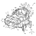
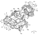
- FIG. 1 is a perspective view of a balancer device 1 according to the first embodiment.
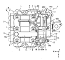
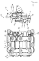
- FIG. 2 is a bottom view of the balancer device 1.
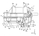
- FIG. 3 is a right side view of the balancer device 1.
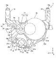
- FIG. 4 is a front view of the balancer device 1.
- FIG. 5 is a rear view of the balancer device 1.
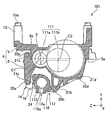
- 6 is a cross-sectional view taken along line S6-S6 of FIG.
- “upper” is an upper direction in the vertical direction when the balancer device 1 is mounted on a vehicle (in-vehicle state)
- “lower” is a lower direction in the vertical direction in the in-vehicle state.
- the balancer device 1 is housed in an oil pan (not shown) attached to the lower part of a cylinder block (not shown) of the engine.
- the engine is, for example, an in-line four-cylinder reciprocating engine.
- the balancer device 1 includes balancer shafts 2 and 3 and a balancer housing 4.
- the balancer shaft 2 is also referred to as a drive shaft 2
- the balancer shaft 3 is also referred to as a driven shaft 3.
- the drive shaft 2 and the driven shaft 3 are accommodated in the balancer housing 4.
- the balancer shafts 2 and 3 are parallel to each other along the longitudinal direction of the engine along the longitudinal direction of the engine, and with respect to a vertical plane passing through the rotational axis of the crankshaft (not shown). It arrange
- the X axis is set in the longitudinal direction of the engine, the Y axis in the vertical direction of the engine, and the Z axis in the horizontal direction of the engine.
- the direction from the front side to the rear side of the engine is the positive X-axis direction
- the direction from the lower side to the upper side of the engine (upward in the vertical direction) is the positive direction of the Y-axis, Is described as the positive direction of the Z-axis.
- the balancer shafts 2 and 3 have an axis (rotation axis) extending in the X-axis direction.
- the balancer shafts 2 and 3 are each provided with a substantially semi-cylindrical balancer weight (not shown) whose center of gravity is offset from the axis of the balancer shafts 2 and 3 when viewed in the X-axis direction. Both balancer weights are always positioned at the same height during the rotation of the balancer shafts 2 and 3.
- a pair of interlocking gears 2a, 3a that mesh with each other is provided at the ends of the balancer shafts 2, 3 in the positive direction of the X axis.
- Reference holes 2b and 3b are formed at the ends of the balancer shafts 2 and 3 in the positive direction of the X axis.
- a positioning clip (not shown) is attached to the reference holes 2b and 3b when the balancer device 1 is attached to the cylinder block.
- a driven gear 2c that meshes with a drive gear (not shown) fixed to the crankshaft is fixed near the X-axis negative direction end of the drive shaft 2 (see FIG. 4).
- the balancer shafts 2 and 3 rotate in synchronization with the crankshaft.
- the speed ratio between the drive gear and the driven gear 2c is 2, and the balancer shafts 2 and 3 rotate at twice the speed of the crankshaft.
- the balancer housing 4 includes an upper housing 5 and a lower housing 6 formed separately from the upper housing 5.
- the upper housing 5 and the lower housing 6 (hereinafter also referred to as balancer housings 5 and 6) are formed in a substantially halved shape that is divided into two parts in the vertical direction, and abut against each other by mating surfaces 5a and 6a parallel to the X axis.
- the balancer housings 5 and 6 are fastened in the Y-axis direction by six housing fastening bolts 7.
- Bearings that rotatably support the balancer shafts 2 and 3 on both sides in the X-axis direction of the weight accommodating portions (not shown) for accommodating the balancer weights of the balancer shafts 2 and 3 inside the balancer housings 5 and 6, respectively. (Not shown) is provided.
- the lower housing 6 is formed with bearing support portions 8 and 9 for accommodating the bearings.
- the bearing support portions 8 and 9 are formed with a larger thickness than other portions of the lower housing 6, and the rigidity is enhanced.
- the bearing support portion 8 is positioned on the X axis negative direction side of the balancer weight, and the bearing support portion 9 is positioned on the X axis positive direction side of the balancer weight.
- the lower surfaces (surfaces on the Y axis negative direction side) of the bearing support portions 8 and 9 have a predetermined width in the X axis direction and extend in the Z axis direction.
- Three of the six housing fastening bolts 7 are arranged in the bearing support portion 8 between the outer side of the balancer shafts 2 and 3 and between the balancer shafts 2 and 3, and are aligned in the Z-axis direction.
- the remaining three are arranged outside the balancer shafts 2 and 3 and between the balancer shafts 2 and 3 in the bearing support 9 and are aligned in the Z-axis direction.
- a positioning hollow pin 10a protrudes upward from the positive end of each leg 10 in the Y-axis direction.
- the positioning hollow pin 10a is press-fitted into the leg portion 10.
- a balancer fastening bolt (not shown) for fastening the balancer housing 4 to the cylinder block is inserted into each leg 10 and the positioning hollow pin 10a from the Y axis negative direction side.
- the oil pump 12 is connected to the X-axis negative direction end of the driven shaft 3 via a speed reduction mechanism 11 as shown in FIG.
- the speed reduction mechanism 11 includes a drive gear 11a and a driven gear 11b.
- the drive gear 11a is fixed to the X axis negative direction end of the driven shaft 3.
- the driven gear 11b is fixed to a drive shaft 12a (see FIG. 4) of the oil pump 12.
- the driven gear 11b has more teeth than the drive gear 11a, and the speed ratio between the drive gear 11a and the driven gear 11b is 1/2. For this reason, the oil pump 12 rotates at half the speed of the balancer shafts 2 and 3.
- the rotation center of the drive shaft of the oil pump 12 is arranged on the Z axis positive direction side and the Y axis negative direction side with respect to the rotation center of the driven shaft 3.
- the oil pump 12 pressurizes the oil sucked from the oil strainer 13 and discharges it to the main oil gallery (not shown).
- the oil discharged to the main oil gallery is mainly sent to each sliding part of the engine for lubrication.
- a part of the oil is used for lubricating the balancer shafts 2 and 3.
- the oil pump 12 is a variable displacement oil pump in which the volume change amount (that is, discharge capacity) of the pump chamber is variable.
- the variable displacement oil pump is a vane pump having a mechanism for reducing the volume change amount of the pump chamber when the pump rotates at high speed.
- any known pump for example, a pump disclosed in JP 2011-111926 A
- JP 2011-111926 A any known pump (for example, a pump disclosed in JP 2011-111926 A) can be used.
- the oil pump 12 includes an oil pump housing 14.
- the oil pump housing 14 includes a pump body 15 and a pump cover 16.
- the pump body 15 and the pump cover 16 are in contact with each other at a mating surface parallel to the YZ plane, and the pump housing 14 and the pump body 15 are assembled by the three pump assembly bolts 17a, and the X is secured by the four pump fastening bolts 17b.
- the oil pump 12 and the balancer housing 4 are fastened together from the shaft negative direction side. As shown in FIG. 4, each of the pump fastening bolts 17 a and 17 b is disposed along the outer periphery of the oil pump housing 14 when viewed in the X-axis direction.
- a plurality of bosses 14 a and 14 b are formed on the outer periphery of the oil pump housing 14.
- Each of the plurality of bosses 14a has a screw hole, and the pump assembly bolt 17a is inserted into the screw hole.
- Each of the plurality of bosses 14b has a screw hole, and a pump fastening bolt 17b is inserted into the screw hole.
- the pump cover 16 is provided with a suction part 18 at the Y-axis negative direction end.
- the suction part 18 has an opening 18d for introducing oil into the oil pump 12.
- the opening 18d opens toward the positive direction of the X axis.
- One end of the oil strainer 13 is connected to the opening 18d.
- the oil strainer 13 extends to the bearing support portion 9 in the positive direction of the X axis.
- the other end (tip portion 13a) of the oil strainer 13 is bent 90 ° toward the Y axis negative direction side at the bearing support portion 9, and opens downward (Y axis negative direction).
- the suction portion 18 and the oil strainer 13 are disposed between adjacent housing fastening bolts 7 in the Z-axis direction.
- the oil strainer 13 and the housing fastening bolt 7 do not interfere in the Y-axis direction. Therefore, the oil strainer 13 can be disposed on the Y axis positive direction side of the head of the housing fastening bolt 7. As a result, the Y-axis direction dimension of the balancer device 1 can be shortened, and the device can be made compact. Further, according to the balancer device 1, the suction portion 18 is disposed at substantially the same position as the driven shaft 3 in the Z-axis direction. In other words, the suction part 18 is arranged not on the drive shaft 2 side but on the driven shaft 3 side.
- the suction portion 18 does not interfere with the driven gear chamber that houses the driven gear 2c. Therefore, the suction part 18 can be arranged so that the suction part 18 and the driven gear chamber partially overlap in the Y-axis direction. As a result, since they can be arranged in an overlapping manner, the dimension of the balancer device 1 in the Y-axis direction can be shortened, and the device can be made compact. Further, the suction portion 18 and the oil strainer 13 are provided so as to be all within the projected area of the oil pump housing 14 when viewed in the X-axis direction. For this reason, the balancer device 1 can be made compact. As shown in FIG.
- two bosses 18c having screw holes 18b are provided at the distal end of the suction portion 18.
- the oil strainer 13 is fastened to the suction portion 18 by inserting the strainer fastening bolt 19 into the screw hole 18b from the X axis positive direction side.
- An imaginary line L1 connecting the centers of the two screw holes 18b is provided obliquely with respect to the surfaces of the bearing support portions 8 and 9 of the balancer housing 4, in other words, the XZ plane. For this reason, the dimension of the suction part 18 in the Z-axis direction can be reduced, and the apparatus can be made compact.
- a suction passage 18a extending in the X-axis direction is formed.
- the suction passage 18a communicates with a pump chamber (not shown) of the oil pump 12 at one end side, and communicates with the oil strainer 13 at the other end side.
- the lower housing 6 includes a first boss 20a and a second boss 20b at the X-axis negative direction end. Each of the first boss 20a and the second boss 20b protrudes downward.
- the protruding heights of the first boss 20a and the second boss 20b are set in a range in which the first boss 20a and the second boss 20b do not protrude downward from the oil pump housing 14.
- the first boss 20a and the second boss 20b are spaced apart in the Z-axis direction.
- a recess 24 is formed between the first boss 20a and the second boss 20b.
- a first screw hole 21a is formed on the distal end side of the first boss 20a.
- a second screw hole 21b is formed on the distal end side of the second boss 20b.
- the lower housing 6 further includes a third boss 20c and a fourth boss 20d.
- the third boss 20c and the fourth boss 20d are disposed above (the Y-axis positive direction side) above the first boss 20a and the second boss 20b.
- the third boss 20c is provided on the same side as the first boss 20a
- the fourth boss 20d is the second boss 20b. It is provided on the same side.
- the third boss 20c is disposed at a position closer to the first boss 20a than the second boss 20b.
- the boss 20d is disposed at a position closer to the second boss 20b than the first boss 20a.
- the third boss 20c is disposed at the same position as the first boss 20a in the Z-axis direction, and the fourth boss 20d is on the Z-axis negative direction side with respect to the second boss 20b. Is arranged.
- a third screw hole 21c is formed in the third boss 20c, and a fourth screw hole 21d is formed in the fourth boss 20d.
- the third boss 20c is formed so as to protrude above the mating surfaces 5a, 6a of the upper housing 5 and the lower housing 6. As a result, the third screw hole 21c is also formed above the mating surfaces 5a and 6a.
- the screw holes 21a to 21d are disposed at positions corresponding to the bosses 14a of the oil pump housing 14. For this reason, the oil pump 12 is fastened to the lower housing 6 by inserting the pump fastening bolts 17b into the screw holes and the screw holes 21a to 21d of the boss 14a from the X axis negative direction side.
- the suction portion 18 is at least partially disposed in a recess 24 formed between the first boss 20a and the second boss 20b.
- the suction portion 18 in the cross section orthogonal to the X axis (in other words, the cross section parallel to the YZ plane), more than half of the suction portion 18 has the center of the screw hole 21a and the screw hole 21b. Are disposed above the virtual line L2 connecting the two.
- the first boss 20 a is reinforced by a reinforcing rib 22 a extending from the lower housing 6.
- the first boss 20a and the bearing support portion 8 are connected by a reinforcing rib 22a extending in the X-axis direction.
- the third boss 20 c is reinforced by reinforcing ribs 22 b extending from the lower housing 6.
- the second boss 20b, the fourth boss 20d, and the bearing support portion 8 are connected by a reinforcing rib 23 formed in a substantially Y shape when viewed from the Y-axis direction.
- the reinforcing rib 23 is provided so as to cover a driven gear chamber (not shown) in which the driven gear 2c is accommodated in the balancer housing 4. Since the driven gear chamber is formed with a smaller thickness than other portions, this configuration can improve the strength of the driven gear chamber.
- the drive shaft 2 rotates at a speed twice that of the crankshaft.
- the driven shaft 3 rotates at the same speed as the drive shaft 2 in the opposite direction to the drive shaft 2 through the transmission of rotational force due to the meshing of the interlocking gears 2a and 3a.
- the balancer weights of the balancer shafts 2 and 3 also rotate in opposite directions to cancel the left and right centrifugal forces of the balancer shafts 2 and 3 themselves. In this way, both balancer weights rotate as the balancer shafts 2 and 3 rotate to transmit the excitation force to the engine, thereby suppressing secondary vibration of the engine.
- the balancer housing 4 and the oil pump housing 14 are separate bodies. Therefore, the design freedom of the balancer device 1 is high. Further, since the first boss 20a and the second boss 20b protrude downward, a large arrangement width of the bosses 20a to 20d in the vertical direction (that is, a width between the support positions of the oil pump 12) is ensured. be able to. For this reason, the support rigidity of the oil pump 12 can be improved.
- the suction portion 18 of the oil pump 12 is at least partially disposed in the recess 24 formed between the first boss 20a and the second boss 20b, the first boss 20a and the second boss 20a It is possible to suppress an increase in the height of the balancer device 1 due to the boss 20b projecting downward.
- more than half of the suction portion 18 is formed at the center of the first screw hole 21a of the first boss 20a and the second screw hole of the second boss 20b. It is arranged above the virtual line L2 connecting the center of 21b. Therefore, an increase in the height of the balancer device 1 can be effectively suppressed.
- the opening 18d of the suction portion 18 opens toward the opposite side to the first boss 20a and the second boss 20b in the X-axis direction. Therefore, an increase in the height of the balancer device 1 can be suppressed.
- the balancer device 1 includes an oil strainer 13 that extends in the X-axis direction.
- the oil strainer 13 has a first end connected to the opening 18d, and a second end (tip 13a) that opens downward. Therefore, it is possible to make the suction portion 18 communicate with a desired position in the oil pan that covers the lower portion of the balancer device 1 while suppressing an increase in the height of the balancer device 1.
- the tip portion 13a can be disposed at a position where the oil can be reliably sucked even when the oil in the oil pan is biased as the vehicle travels on a slope.
- the third boss 20c is formed so as to protrude above the mating surfaces 5a, 6a of the upper housing 5 and the lower housing 6. Therefore, the distance between the first boss 20a and the third boss 20c can be further increased without increasing the height of the balancer device 1. For this reason, the support rigidity of the oil pump 12 can be further improved.
- the fourth boss 20d may be formed so as to protrude above the mating surfaces 5a, 6a of the upper housing 5 and the lower housing 6.
- the first boss 20a and the third boss 20c are reinforced by the reinforcing ribs 22a and 22b extending from the lower housing 6, respectively.
- the second boss 20 b and the fourth boss 20 d are reinforced by reinforcing ribs 23 extending from the lower housing 6.
- the support rigidity of the oil pump 12 can be further increased.
- the first boss 20a, the second boss 20b, and the fourth boss 20d are connected to the bearing support portion 8 having relatively high rigidity, so that the support rigidity can be further increased. it can.
- the reinforcing rib 23 connects the second boss 20b, the fourth boss 20d, and the bearing support portion 8 to each other, the support rigidity can be further increased.
- at least one of the bosses 20a to 20d may be reinforced by a reinforcing rib.
- at least one of the first boss 20a and the second boss 20b, at least one of the third boss 20c and the fourth boss 20d, the bearing support portion 8, May be connected.
- the balancer device 1 as the balancer shaft, the drive shaft 2 to which the rotational force of the crankshaft is transmitted, and the rotational force transmitted from the drive shaft 2 is rotated in the direction opposite to the drive shaft 2 by the rotational force. And a driven shaft 3 to be provided.
- the drive gear is fixed to the driven shaft, and the driven gear 2c is fixed to the drive shaft 12a of the oil pump 12. Then, the rotational force of the driven shaft 3 is transmitted to the oil pump 12 via the speed reduction mechanism 11. Therefore, the dimension in the Y-axis direction of the balancer device 1 can be reduced, and the device can be made compact. Further, since the oil pump 12 can be driven at a relatively low speed, the pump efficiency is improved, and as a result, the fuel consumption is improved. Moreover, generation
- FIG. 7 is a perspective view of the balancer device 101 according to the second embodiment.
- FIG. 8 is a perspective view of the balancer device 101 and shows a state in which the oil pump 112 is removed from the balancer device 101.
- FIG. 9 is a bottom view of the balancer device 101.
- FIG. 10 is a bottom view of the balancer device 101 and shows a state in which the oil pump 112 is removed from the balancer device 101.
- FIG. 11 is a perspective view of the balancer device 101 according to the second embodiment with the oil pump 112 removed.
- FIG. 12 is a cross-sectional view of the balancer device 101 corresponding to FIG.
- the oil pump 112 includes a suction part 118.
- the suction unit 118 has an opening 118d for introducing oil into the oil pump 112.
- the opening 118d opens in the Y-axis negative direction (downward).
- the suction part 118 includes a strainer part 113.
- the strainer portion 113 extends linearly from the opening portion 118d downward by a small distance, and the tip end portion 13a opens downward.
- the strainer portion 113 is formed integrally with the suction portion 118. According to this configuration, the number of parts can be reduced. In addition, the strainer portion 113 facilitates oil inhalation.
- the speed reduction mechanism 111 includes a drive gear 111a and a driven gear 111b.
- a recess 24 formed between the first boss 20a and the second boss 20b is disposed immediately below the driven shaft 3.
- the axis C1 of the driven shaft 3 is disposed above the axis C2 of the driven gear 111b.
- the depth of the recess 24 can be increased by the amount that the axis C1 of the driven shaft 3 is offset above the axis C2 of the driven gear 111b. That is, since the depth of the recess 24 that accommodates the suction portion 118 is increased, the suction portion 118 can be accommodated deeper in the recess 24. Therefore, an increase in the height of the balancer device 101 can be suppressed.
- the balancer housing 4 is formed as a separate body from the first balancer housing and the first balancer housing, instead of the upper housing 5 and the lower housing 6, and is connected to the first balancer housing. And a housing.
- the first balancer housing and the second balancer housing may be divided in a direction perpendicular to the axial direction of the balancer shafts 2 and 3. That is, the balancer housing may be divided into a front balancer housing and a rear balancer housing.
- the oil pump 12 may be supported at three points or five or more points instead of the four-point support by the first bosses 20a to 20d in the above-described embodiments.
- the oil pump 12 may be supported at three points by 20a to 20c.
- Pump cover 17a Pump assembly bolt 17b ... Pump fastening bolt 18, 118 ... Suction part 18a ... Suction passage 18b ... Screw hole 18c ... Boss 18d, 118d ... Opening 19 ... Strainer fastening bolt 20a ... First boss 20b ... Second boss 20c ... Third boss 20d ... Fourth boss 21a, 21b, 21c, 21d ... Screw holes 22a, 22b, 23 ... Reinforcement ribs 24 ... Recesses 113 ... Strainer L1, ... Virtual lines C1, C2 ... Shaft core
Landscapes
- Engineering & Computer Science (AREA)
- General Engineering & Computer Science (AREA)
- Mechanical Engineering (AREA)
- Physics & Mathematics (AREA)
- Acoustics & Sound (AREA)
- Aviation & Aerospace Engineering (AREA)
- Chemical & Material Sciences (AREA)
- Combustion & Propulsion (AREA)
- Lubrication Of Internal Combustion Engines (AREA)
- Lubrication Details And Ventilation Of Internal Combustion Engines (AREA)
- Rotary Pumps (AREA)
- Details And Applications Of Rotary Liquid Pumps (AREA)
Abstract
Description
本発明の実施例1について説明する。図1は実施例1のバランサ装置1の斜視図である。図2はバランサ装置1の底面図である。図3はバランサ装置1の右側面図である。図4はバランサ装置1の正面図である。図5はバランサ装置1の背面図である。図6は図3のS6-S6線に沿った断面図である。本願において、「上方」とは、バランサ装置1を車両に搭載した状態(車載状態)における鉛直方向上方であり、「下方」とは、車載状態における鉛直方向下方である。
本発明の実施例2について説明する。以下の説明において、実施例1と同様の構成要素には、実施例1と同一の符号を付している。また、実施例1の構成要素に対応する構成要素には、下2桁に実施例1と同一の符号を付している。以下、実施例1と異なる点についてのみ説明する。実施例2のバランサ装置101は、オイルポンプ12に代えてオイルポンプ112を備えている。バランサ装置101は、特に断らない点についてはバランサ装置1と同一の構成を備えている。図7は実施例2のバランサ装置101の斜視図である。図8は、バランサ装置101の斜視図であり、バランサ装置101からオイルポンプ112が取り外された状態を示している。図9はバランサ装置101の底面図である。図10はバランサ装置101の底面図であり、バランサ装置101からオイルポンプ112が取り外された状態を示している。図11は、オイルポンプ112が取り外された実施例2のバランサ装置101の斜視図である。図12は、図6に対応するバランサ装置101の断面図である。
2…バランサシャフト(ドライブシャフト)
2c…ドリブンギア
3…バランサシャフト(ドリブンシャフト)
2a,3a…連動ギア
2b,3b…基準穴
4…バランサハウジング
5…バランサハウジング(アッパハウジング)
6…バランサハウジング(ロアハウジング)
5a,6a…合わせ面
7…ハウジング締結ボルト
8,9…軸受支持部
10…脚部
10a…中空ピン
11,111…減速機構
11a,111a…ドライブギア
11b,111b…ドリブンギア
12,112…オイルポンプ
12a…駆動軸
13…オイルストレーナ
13a…先端部
14…オイルポンプハウジング
14a,14b…ボス
15…ポンプボディ
16…ポンプカバー
17a…ポンプ組立ボルト
17b…ポンプ締結ボルト
18,118…吸入部
18a…吸入通路
18b…ねじ穴
18c…ボス
18d,118d…開口部
19…ストレーナ締結ボルト
20a…第1のボス
20b…第2のボス
20c…第3のボス
20d…第4のボス
21a,21b,21c,21d…ねじ穴
22a,22b,23…補強リブ
24…凹部
113…ストレーナ部
L1,…仮想線
C1,C2…軸芯
Claims (17)
- バランサ装置であって、
回転駆動されるバランサシャフトと、
前記バランサシャフトを回転可能に収容するバランサハウジングと、
前記バランサハウジングと別体に形成されたオイルポンプハウジングを有し、前記バランサハウジングに取り付けられるオイルポンプと
を備え、
前記バランサハウジングは、アッパハウジングと、該アッパハウジングと別体に形成されたロアハウジングと、を備え、
前記ロアハウジングは、
前記オイルポンプを前記ロアハウジングに締結するための第1のボスおよび第2のボスであって、前記バランサシャフトの軸線方向の一端側において下方に向けて突出する第1のボスおよび第2のボスと、
前記オイルポンプを前記ロアハウジングに締結するための第3のボスであって、前記第1のボスおよび前記第2のボスよりも上方に配置された第3のボスと
を備え、
前記第1のボスと前記第2のボスとは、それらの間に凹部が形成されるように、前記軸線方向と直交する方向に離間して配置され、
前記オイルポンプは、該オイルポンプにオイルを導入するための開口部を有する吸入部を備え、
前記吸入部は、少なくとも部分的に前記凹部内に配置される
バランサ装置。 - 請求項1に記載のバランサ装置であって、
前記ロアハウジングは、前記オイルポンプを前記ロアハウジングに締結するための第4のボスであって、前記第1のボスおよび前記第2のボスよりも上方に配置された第4のボスを備える
バランサ装置。 - 請求項1に記載のバランサ装置であって、
前記第1のボスは、その先端側に第1のねじ穴を備え、
前記第2のボスは、その先端側に第2のねじ穴を備え、
前記軸線方向と直交する断面において、前記吸入部の半分以上が、前記第1のねじ穴の中心と前記第2のねじ穴の中心とを結ぶ仮想線よりも上方に配置されている
バランサ装置。 - 請求項1に記載のバランサ装置であって、
前記開口部は、前記軸線方向における他端側に向けて開口している
バランサ装置。 - 請求項4に記載のバランサ装置であって、
前記軸線方向に延在するストレーナであって、前記開口部に接続される第1の端部と、下方に向けて開口する第2の端部と、を有するストレーナを備える
バランサ装置。 - 請求項1に記載のバランサ装置であって、
前記開口部は、下方に向けて開口している
バランサ装置。 - 請求項6に記載のバランサ装置であって、
前記吸入部は、前記開口部から下方に向けて延在するストレーナ部を備え、
前記ストレーナ部は、前記吸入部と一体的に形成されている
バランサ装置。 - 請求項2に記載のバランサ装置であって、
前記第3のボスおよび前記第4のボスのうちの少なくとも一方は、前記アッパハウジングと前記ロアハウジングとの合わせ面よりも上方に突出するように形成されている
バランサ装置。 - 請求項2に記載のバランサ装置であって、
前記第1ないし第4のボスのうちの少なくとも1つは、前記ロアハウジングから延在する補強リブにより補強されている
バランサ装置。 - 請求項9に記載のバランサ装置であって、
前記ロアハウジングは、前記バランサシャフトを回転可能に支持する軸受が部分的に収容される軸受支持部を備え、
前記補強リブは、前記軸受支持部に接続されている
バランサ装置。 - 請求項10に記載のバランサ装置であって、
前記補強リブは、前記第1のボスおよび前記第2のボスのうちの少なくとも一方と、前記第3のボスおよび前記第4のボスのうちの少なくとも一方と、前記軸受支持部と、を接続している
バランサ装置。 - 請求項1に記載のバランサ装置であって、
前記バランサシャフトは、エンジンのクランクシャフトの回転力が伝達されるドライブシャフトと、前記ドライブシャフトから伝達される回転力により前記ドライブシャフトとは逆の方向に回転するドリブンシャフトと、を備え、
前記ドライブシャフトまたは前記ドリブンシャフトによって、前記オイルポンプに回転力が伝達される
バランサ装置。 - バランサ装置であって、
回転駆動されるバランサシャフトと、
前記バランサシャフトを回転可能に収容するバランサハウジングであって、第1のバランサハウジングと、該第1のバランサハウジングと別体に形成され、該第1のバランサハウジングに連結される第2のバランサハウジングと、を有するバランサハウジングと、
前記バランサハウジングと別体に形成されたオイルポンプハウジングを有し、前記第1のバランサハウジングに取り付けられるオイルポンプと
を備え、
前記バランサハウジングは、
前記オイルポンプを前記第1のバランサハウジングに締結するための第1のボスおよび第2のボスであって、前記バランサシャフトの軸線方向の一端側において下方に向けて突出する第1のボスおよび第2のボスと、
前記オイルポンプを前記ロアハウジングに締結するための第3のボスであって、前記第1のボスおよび前記第2のボスよりも上方に配置された第3のボスと
を備え、
前記第1のボスと前記第2のボスとは、それらの間に凹部が形成されるように、前記軸線方向と直交する方向に離間して配置され、
オイルポンプは、該オイルポンプにオイルを導入するための開口部を有する吸入部を備え、
前記吸入部は、少なくとも部分的に前記凹部内に配置される
バランサ装置。 - 請求項13に記載のバランサ装置であって、
前記第1のボスは、その先端側に第1のねじ穴を備え、
前記第2のボスは、その先端側に第2のねじ穴を備え、
前記軸線方向と直交する断面において、前記吸入部の半分以上が、前記第1のねじ穴の中心と前記第2のねじ穴の中心とを結ぶ仮想線よりも上方に配置されている
バランサ装置。 - 請求項13に記載のバランサ装置であって、
前記バランサ装置は、減速機構を備え、
前記オイルポンプは、吐出容量が可変の可変容量形型オイルポンプであり、
前記バランサシャフトの回転力は、前記減速機構を介して前記オイルポンプに伝達される
バランサ装置。 - 請求項15に記載のバランサ装置であって、
前記バランサシャフトは、エンジンのクランクシャフトの回転力が伝達されるドライブシャフトと、前記ドライブシャフトから伝達される回転力により前記ドライブシャフトとは逆の方向に回転するドリブンシャフトと、を備え、
前記減速機構は、ドライブギアと、該ドライブギアよりも歯数が多いドリブンギアと、を備え、
前記ドライブギアは、前記ドリブンシャフトに固定され、
前記ドリブンギアは、前記オイルポンプの駆動軸に固定された
バランサ装置。 - 請求項16に記載のバランサ装置であって、
前記凹部は、前記ドリブンシャフトの直下に配置され、
前記ドリブンシャフトの軸芯は、前記ドリブンギアの軸芯よりも上方に配置されている
バランサ装置。
Priority Applications (5)
| Application Number | Priority Date | Filing Date | Title |
|---|---|---|---|
| CN201780007925.0A CN109073039B (zh) | 2016-02-19 | 2017-02-14 | 平衡装置 |
| JP2018500127A JP6497569B2 (ja) | 2016-02-19 | 2017-02-14 | バランサ装置 |
| MX2018009911A MX2018009911A (es) | 2016-02-19 | 2017-02-14 | Aparato compensador. |
| ES201890052A ES2695473B2 (es) | 2016-02-19 | 2017-02-14 | Aparato equilibrador |
| US15/998,961 US20200332856A1 (en) | 2016-02-19 | 2017-02-14 | Balancer apparatus |
Applications Claiming Priority (2)
| Application Number | Priority Date | Filing Date | Title |
|---|---|---|---|
| JP2016029431 | 2016-02-19 | ||
| JP2016-029431 | 2016-02-19 |
Publications (1)
| Publication Number | Publication Date |
|---|---|
| WO2017141917A1 true WO2017141917A1 (ja) | 2017-08-24 |
Family
ID=59626025
Family Applications (1)
| Application Number | Title | Priority Date | Filing Date |
|---|---|---|---|
| PCT/JP2017/005368 Ceased WO2017141917A1 (ja) | 2016-02-19 | 2017-02-14 | バランサ装置 |
Country Status (6)
| Country | Link |
|---|---|
| US (1) | US20200332856A1 (ja) |
| JP (1) | JP6497569B2 (ja) |
| CN (1) | CN109073039B (ja) |
| ES (1) | ES2695473B2 (ja) |
| MX (1) | MX2018009911A (ja) |
| WO (1) | WO2017141917A1 (ja) |
Cited By (4)
| Publication number | Priority date | Publication date | Assignee | Title |
|---|---|---|---|---|
| WO2019171759A1 (ja) * | 2018-03-07 | 2019-09-12 | 日立オートモティブシステムズ株式会社 | 内燃機関用バランサ装置 |
| WO2021053848A1 (ja) * | 2019-09-18 | 2021-03-25 | 日立Astemo株式会社 | オイルポンプ付きバランサ装置 |
| JP2021127743A (ja) * | 2020-02-14 | 2021-09-02 | マツダ株式会社 | バランサ付きエンジン |
| WO2023037739A1 (ja) * | 2021-09-10 | 2023-03-16 | 日立Astemo株式会社 | 内燃機関のバランサ装置、及びオイルポンプ付きバランサ装置 |
Citations (3)
| Publication number | Priority date | Publication date | Assignee | Title |
|---|---|---|---|---|
| JP2008144653A (ja) * | 2006-12-08 | 2008-06-26 | Mazda Motor Corp | エンジンのバランサ装置 |
| US20100012075A1 (en) * | 2008-07-16 | 2010-01-21 | Polaris Industries Inc. | Wet oil sump for four cycle engine |
| JP2013122302A (ja) * | 2011-12-12 | 2013-06-20 | Honda Motor Co Ltd | 内燃機関のバランサハウジング構造 |
Family Cites Families (6)
| Publication number | Priority date | Publication date | Assignee | Title |
|---|---|---|---|---|
| CA2316152C (en) * | 1999-09-03 | 2004-10-05 | Honda Giken Kogyo Kabushiki Kaisha | Balance shaft for engine balancing systems |
| DE60209291T8 (de) * | 2001-12-18 | 2007-05-10 | Honda Giken Kogyo K.K. | Ausgleichsvorrichtung für einen Motor |
| JP4858354B2 (ja) * | 2007-08-10 | 2012-01-18 | スズキ株式会社 | エンジンのバランサ装置 |
| JP5186424B2 (ja) * | 2009-03-27 | 2013-04-17 | 株式会社音戸工作所 | エンジンのバランサ装置 |
| US9127555B2 (en) * | 2010-12-21 | 2015-09-08 | Solar Turbines Incorporated | Method for balancing rotating assembly of gas turbine engine |
| CN106150591B (zh) * | 2016-08-30 | 2019-01-15 | 潍柴动力股份有限公司 | 一种发动机及其机油泵内置安装结构 |
-
2017
- 2017-02-14 US US15/998,961 patent/US20200332856A1/en not_active Abandoned
- 2017-02-14 CN CN201780007925.0A patent/CN109073039B/zh active Active
- 2017-02-14 MX MX2018009911A patent/MX2018009911A/es unknown
- 2017-02-14 WO PCT/JP2017/005368 patent/WO2017141917A1/ja not_active Ceased
- 2017-02-14 ES ES201890052A patent/ES2695473B2/es active Active
- 2017-02-14 JP JP2018500127A patent/JP6497569B2/ja active Active
Patent Citations (3)
| Publication number | Priority date | Publication date | Assignee | Title |
|---|---|---|---|---|
| JP2008144653A (ja) * | 2006-12-08 | 2008-06-26 | Mazda Motor Corp | エンジンのバランサ装置 |
| US20100012075A1 (en) * | 2008-07-16 | 2010-01-21 | Polaris Industries Inc. | Wet oil sump for four cycle engine |
| JP2013122302A (ja) * | 2011-12-12 | 2013-06-20 | Honda Motor Co Ltd | 内燃機関のバランサハウジング構造 |
Cited By (11)
| Publication number | Priority date | Publication date | Assignee | Title |
|---|---|---|---|---|
| WO2019171759A1 (ja) * | 2018-03-07 | 2019-09-12 | 日立オートモティブシステムズ株式会社 | 内燃機関用バランサ装置 |
| JP2019157878A (ja) * | 2018-03-07 | 2019-09-19 | 日立オートモティブシステムズ株式会社 | 内燃機関用バランサ装置 |
| JP7075783B2 (ja) | 2018-03-07 | 2022-05-26 | 日立Astemo株式会社 | 内燃機関用バランサ装置 |
| US11391341B2 (en) | 2018-03-07 | 2022-07-19 | Hitachi Astemo, Ltd. | Balancer device for internal combustion engines |
| WO2021053848A1 (ja) * | 2019-09-18 | 2021-03-25 | 日立Astemo株式会社 | オイルポンプ付きバランサ装置 |
| ES2914454R1 (es) * | 2019-09-18 | 2022-08-02 | Hitachi Astemo Ltd | Aparato equilibrador equipado con bomba de aceite |
| JP2021127743A (ja) * | 2020-02-14 | 2021-09-02 | マツダ株式会社 | バランサ付きエンジン |
| JP7327196B2 (ja) | 2020-02-14 | 2023-08-16 | マツダ株式会社 | バランサ付きエンジン |
| WO2023037739A1 (ja) * | 2021-09-10 | 2023-03-16 | 日立Astemo株式会社 | 内燃機関のバランサ装置、及びオイルポンプ付きバランサ装置 |
| JP7641207B2 (ja) | 2021-09-10 | 2025-03-06 | 日立Astemo株式会社 | 内燃機関のバランサ装置 |
| US12510007B2 (en) | 2021-09-10 | 2025-12-30 | Hitachi Astemo, Ltd. | Balancer device for internal combustion engine and balancer device with oil pump |
Also Published As
| Publication number | Publication date |
|---|---|
| ES2695473B2 (es) | 2019-07-29 |
| MX2018009911A (es) | 2018-09-11 |
| ES2695473A2 (es) | 2019-01-04 |
| JP6497569B2 (ja) | 2019-04-10 |
| CN109073039A (zh) | 2018-12-21 |
| CN109073039B (zh) | 2020-05-22 |
| JPWO2017141917A1 (ja) | 2018-10-11 |
| US20200332856A1 (en) | 2020-10-22 |
| ES2695473R1 (es) | 2019-01-25 |
Similar Documents
| Publication | Publication Date | Title |
|---|---|---|
| CN103161877B (zh) | 用于内燃机的平衡器装置 | |
| JP6497569B2 (ja) | バランサ装置 | |
| US10731551B2 (en) | Balancer device for internal combustion engine | |
| JP6601147B2 (ja) | エンジンのバランサ装置及び自動二輪車 | |
| CN1287215A (zh) | 用于发动机平衡系统的平衡轴 | |
| KR102074538B1 (ko) | 내연 기관의 밸런서 장치 | |
| US8047176B2 (en) | Balancer apparatus for an engine | |
| JP5357132B2 (ja) | クランクケース一体型バランサ装置 | |
| JP4947527B2 (ja) | 内燃機関のバランサ装置 | |
| KR20100063441A (ko) | 차량용 밸런스샤프트 모듈 | |
| JP2001140985A (ja) | バランス軸 | |
| CN104508321A (zh) | 内燃机 | |
| JP4720289B2 (ja) | 内燃機関の振動低減装置 | |
| JP4369185B2 (ja) | 並列多気筒エンジン | |
| JP2022139430A (ja) | バランサ装置及びこのバランサ装置を備えた内燃機関 | |
| JP3730557B2 (ja) | エンジン用つり合い装置のバランサシャフト | |
| JP6569468B2 (ja) | エンジンのバランサ装置及び自動二輪車 | |
| US10907516B2 (en) | Balancer device for internal combustion engine | |
| JP5385365B2 (ja) | 内燃機関のバランサハウジング構造 | |
| JP5478599B2 (ja) | 内燃機関のバランサ装置 | |
| JP6569467B2 (ja) | エンジンのバランサ装置及び自動二輪車 | |
| JP7085466B2 (ja) | バランサ装置 | |
| CN121251753A (zh) | 发动机的平衡轴机构以及车辆 | |
| JP2006063838A (ja) | 内燃機関の潤滑装置 | |
| JP2019044919A (ja) | バランサ装置 |
Legal Events
| Date | Code | Title | Description |
|---|---|---|---|
| 121 | Ep: the epo has been informed by wipo that ep was designated in this application |
Ref document number: 17753174 Country of ref document: EP Kind code of ref document: A1 |
|
| ENP | Entry into the national phase |
Ref document number: 2018500127 Country of ref document: JP Kind code of ref document: A |
|
| WWE | Wipo information: entry into national phase |
Ref document number: MX/A/2018/009911 Country of ref document: MX |
|
| WWE | Wipo information: entry into national phase |
Ref document number: P201890052 Country of ref document: ES |
|
| NENP | Non-entry into the national phase |
Ref country code: DE |
|
| 122 | Ep: pct application non-entry in european phase |
Ref document number: 17753174 Country of ref document: EP Kind code of ref document: A1 |