WO2017138243A1 - Dispositif à cycle frigorifique - Google Patents
Dispositif à cycle frigorifique Download PDFInfo
- Publication number
- WO2017138243A1 WO2017138243A1 PCT/JP2016/087008 JP2016087008W WO2017138243A1 WO 2017138243 A1 WO2017138243 A1 WO 2017138243A1 JP 2016087008 W JP2016087008 W JP 2016087008W WO 2017138243 A1 WO2017138243 A1 WO 2017138243A1
- Authority
- WO
- WIPO (PCT)
- Prior art keywords
- refrigerant
- refrigeration cycle
- temperature
- cooling
- branch pipe
- Prior art date
Links
- 238000005057 refrigeration Methods 0.000 title claims abstract description 89
- 238000001816 cooling Methods 0.000 claims abstract description 106
- 238000011144 upstream manufacturing Methods 0.000 claims abstract description 34
- 239000003507 refrigerant Substances 0.000 claims description 179
- 239000003570 air Substances 0.000 claims description 43
- 238000004781 supercooling Methods 0.000 claims description 15
- 239000012080 ambient air Substances 0.000 claims description 2
- 238000009833 condensation Methods 0.000 abstract description 15
- 230000005494 condensation Effects 0.000 abstract description 15
- 230000007423 decrease Effects 0.000 abstract description 6
- 239000002826 coolant Substances 0.000 abstract description 3
- 239000007788 liquid Substances 0.000 description 65
- 239000012071 phase Substances 0.000 description 16
- 230000000694 effects Effects 0.000 description 14
- 239000007791 liquid phase Substances 0.000 description 11
- 230000006866 deterioration Effects 0.000 description 5
- 238000010586 diagram Methods 0.000 description 4
- 238000001514 detection method Methods 0.000 description 3
- 238000010438 heat treatment Methods 0.000 description 3
- XAGFODPZIPBFFR-UHFFFAOYSA-N aluminium Chemical compound [Al] XAGFODPZIPBFFR-UHFFFAOYSA-N 0.000 description 2
- 229910052782 aluminium Inorganic materials 0.000 description 2
- 230000005514 two-phase flow Effects 0.000 description 2
- 238000004378 air conditioning Methods 0.000 description 1
- 238000007664 blowing Methods 0.000 description 1
- 230000006835 compression Effects 0.000 description 1
- 238000007906 compression Methods 0.000 description 1
- 239000000470 constituent Substances 0.000 description 1
- 238000010276 construction Methods 0.000 description 1
- 239000012530 fluid Substances 0.000 description 1
- 238000007710 freezing Methods 0.000 description 1
- 230000008014 freezing Effects 0.000 description 1
- 238000009434 installation Methods 0.000 description 1
- 238000000034 method Methods 0.000 description 1
Images


Classifications
-
- F—MECHANICAL ENGINEERING; LIGHTING; HEATING; WEAPONS; BLASTING
- F25—REFRIGERATION OR COOLING; COMBINED HEATING AND REFRIGERATION SYSTEMS; HEAT PUMP SYSTEMS; MANUFACTURE OR STORAGE OF ICE; LIQUEFACTION SOLIDIFICATION OF GASES
- F25B—REFRIGERATION MACHINES, PLANTS OR SYSTEMS; COMBINED HEATING AND REFRIGERATION SYSTEMS; HEAT PUMP SYSTEMS
- F25B5/00—Compression machines, plants or systems, with several evaporator circuits, e.g. for varying refrigerating capacity
- F25B5/02—Compression machines, plants or systems, with several evaporator circuits, e.g. for varying refrigerating capacity arranged in parallel
-
- F—MECHANICAL ENGINEERING; LIGHTING; HEATING; WEAPONS; BLASTING
- F25—REFRIGERATION OR COOLING; COMBINED HEATING AND REFRIGERATION SYSTEMS; HEAT PUMP SYSTEMS; MANUFACTURE OR STORAGE OF ICE; LIQUEFACTION SOLIDIFICATION OF GASES
- F25B—REFRIGERATION MACHINES, PLANTS OR SYSTEMS; COMBINED HEATING AND REFRIGERATION SYSTEMS; HEAT PUMP SYSTEMS
- F25B1/00—Compression machines, plants or systems with non-reversible cycle
-
- F—MECHANICAL ENGINEERING; LIGHTING; HEATING; WEAPONS; BLASTING
- F24—HEATING; RANGES; VENTILATING
- F24F—AIR-CONDITIONING; AIR-HUMIDIFICATION; VENTILATION; USE OF AIR CURRENTS FOR SCREENING
- F24F1/00—Room units for air-conditioning, e.g. separate or self-contained units or units receiving primary air from a central station
- F24F1/06—Separate outdoor units, e.g. outdoor unit to be linked to a separate room comprising a compressor and a heat exchanger
- F24F1/20—Electric components for separate outdoor units
- F24F1/24—Cooling of electric components
-
- F—MECHANICAL ENGINEERING; LIGHTING; HEATING; WEAPONS; BLASTING
- F25—REFRIGERATION OR COOLING; COMBINED HEATING AND REFRIGERATION SYSTEMS; HEAT PUMP SYSTEMS; MANUFACTURE OR STORAGE OF ICE; LIQUEFACTION SOLIDIFICATION OF GASES
- F25B—REFRIGERATION MACHINES, PLANTS OR SYSTEMS; COMBINED HEATING AND REFRIGERATION SYSTEMS; HEAT PUMP SYSTEMS
- F25B40/00—Subcoolers, desuperheaters or superheaters
- F25B40/02—Subcoolers
-
- F—MECHANICAL ENGINEERING; LIGHTING; HEATING; WEAPONS; BLASTING
- F25—REFRIGERATION OR COOLING; COMBINED HEATING AND REFRIGERATION SYSTEMS; HEAT PUMP SYSTEMS; MANUFACTURE OR STORAGE OF ICE; LIQUEFACTION SOLIDIFICATION OF GASES
- F25B—REFRIGERATION MACHINES, PLANTS OR SYSTEMS; COMBINED HEATING AND REFRIGERATION SYSTEMS; HEAT PUMP SYSTEMS
- F25B41/00—Fluid-circulation arrangements
- F25B41/30—Expansion means; Dispositions thereof
- F25B41/31—Expansion valves
- F25B41/34—Expansion valves with the valve member being actuated by electric means, e.g. by piezoelectric actuators
-
- F—MECHANICAL ENGINEERING; LIGHTING; HEATING; WEAPONS; BLASTING
- F25—REFRIGERATION OR COOLING; COMBINED HEATING AND REFRIGERATION SYSTEMS; HEAT PUMP SYSTEMS; MANUFACTURE OR STORAGE OF ICE; LIQUEFACTION SOLIDIFICATION OF GASES
- F25B—REFRIGERATION MACHINES, PLANTS OR SYSTEMS; COMBINED HEATING AND REFRIGERATION SYSTEMS; HEAT PUMP SYSTEMS
- F25B49/00—Arrangement or mounting of control or safety devices
- F25B49/02—Arrangement or mounting of control or safety devices for compression type machines, plants or systems
-
- F—MECHANICAL ENGINEERING; LIGHTING; HEATING; WEAPONS; BLASTING
- F25—REFRIGERATION OR COOLING; COMBINED HEATING AND REFRIGERATION SYSTEMS; HEAT PUMP SYSTEMS; MANUFACTURE OR STORAGE OF ICE; LIQUEFACTION SOLIDIFICATION OF GASES
- F25B—REFRIGERATION MACHINES, PLANTS OR SYSTEMS; COMBINED HEATING AND REFRIGERATION SYSTEMS; HEAT PUMP SYSTEMS
- F25B2313/00—Compression machines, plants or systems with reversible cycle not otherwise provided for
- F25B2313/023—Compression machines, plants or systems with reversible cycle not otherwise provided for using multiple indoor units
-
- F—MECHANICAL ENGINEERING; LIGHTING; HEATING; WEAPONS; BLASTING
- F25—REFRIGERATION OR COOLING; COMBINED HEATING AND REFRIGERATION SYSTEMS; HEAT PUMP SYSTEMS; MANUFACTURE OR STORAGE OF ICE; LIQUEFACTION SOLIDIFICATION OF GASES
- F25B—REFRIGERATION MACHINES, PLANTS OR SYSTEMS; COMBINED HEATING AND REFRIGERATION SYSTEMS; HEAT PUMP SYSTEMS
- F25B2313/00—Compression machines, plants or systems with reversible cycle not otherwise provided for
- F25B2313/031—Sensor arrangements
- F25B2313/0315—Temperature sensors near the outdoor heat exchanger
-
- F—MECHANICAL ENGINEERING; LIGHTING; HEATING; WEAPONS; BLASTING
- F25—REFRIGERATION OR COOLING; COMBINED HEATING AND REFRIGERATION SYSTEMS; HEAT PUMP SYSTEMS; MANUFACTURE OR STORAGE OF ICE; LIQUEFACTION SOLIDIFICATION OF GASES
- F25B—REFRIGERATION MACHINES, PLANTS OR SYSTEMS; COMBINED HEATING AND REFRIGERATION SYSTEMS; HEAT PUMP SYSTEMS
- F25B2400/00—General features or devices for refrigeration machines, plants or systems, combined heating and refrigeration systems or heat-pump systems, i.e. not limited to a particular subgroup of F25B
- F25B2400/13—Economisers
-
- F—MECHANICAL ENGINEERING; LIGHTING; HEATING; WEAPONS; BLASTING
- F25—REFRIGERATION OR COOLING; COMBINED HEATING AND REFRIGERATION SYSTEMS; HEAT PUMP SYSTEMS; MANUFACTURE OR STORAGE OF ICE; LIQUEFACTION SOLIDIFICATION OF GASES
- F25B—REFRIGERATION MACHINES, PLANTS OR SYSTEMS; COMBINED HEATING AND REFRIGERATION SYSTEMS; HEAT PUMP SYSTEMS
- F25B2600/00—Control issues
- F25B2600/25—Control of valves
- F25B2600/2501—Bypass valves
-
- F—MECHANICAL ENGINEERING; LIGHTING; HEATING; WEAPONS; BLASTING
- F25—REFRIGERATION OR COOLING; COMBINED HEATING AND REFRIGERATION SYSTEMS; HEAT PUMP SYSTEMS; MANUFACTURE OR STORAGE OF ICE; LIQUEFACTION SOLIDIFICATION OF GASES
- F25B—REFRIGERATION MACHINES, PLANTS OR SYSTEMS; COMBINED HEATING AND REFRIGERATION SYSTEMS; HEAT PUMP SYSTEMS
- F25B2600/00—Control issues
- F25B2600/25—Control of valves
- F25B2600/2513—Expansion valves
-
- F—MECHANICAL ENGINEERING; LIGHTING; HEATING; WEAPONS; BLASTING
- F25—REFRIGERATION OR COOLING; COMBINED HEATING AND REFRIGERATION SYSTEMS; HEAT PUMP SYSTEMS; MANUFACTURE OR STORAGE OF ICE; LIQUEFACTION SOLIDIFICATION OF GASES
- F25B—REFRIGERATION MACHINES, PLANTS OR SYSTEMS; COMBINED HEATING AND REFRIGERATION SYSTEMS; HEAT PUMP SYSTEMS
- F25B2600/00—Control issues
- F25B2600/25—Control of valves
- F25B2600/2515—Flow valves
-
- F—MECHANICAL ENGINEERING; LIGHTING; HEATING; WEAPONS; BLASTING
- F25—REFRIGERATION OR COOLING; COMBINED HEATING AND REFRIGERATION SYSTEMS; HEAT PUMP SYSTEMS; MANUFACTURE OR STORAGE OF ICE; LIQUEFACTION SOLIDIFICATION OF GASES
- F25B—REFRIGERATION MACHINES, PLANTS OR SYSTEMS; COMBINED HEATING AND REFRIGERATION SYSTEMS; HEAT PUMP SYSTEMS
- F25B2600/00—Control issues
- F25B2600/25—Control of valves
- F25B2600/2519—On-off valves
-
- F—MECHANICAL ENGINEERING; LIGHTING; HEATING; WEAPONS; BLASTING
- F25—REFRIGERATION OR COOLING; COMBINED HEATING AND REFRIGERATION SYSTEMS; HEAT PUMP SYSTEMS; MANUFACTURE OR STORAGE OF ICE; LIQUEFACTION SOLIDIFICATION OF GASES
- F25B—REFRIGERATION MACHINES, PLANTS OR SYSTEMS; COMBINED HEATING AND REFRIGERATION SYSTEMS; HEAT PUMP SYSTEMS
- F25B2700/00—Sensing or detecting of parameters; Sensors therefor
- F25B2700/21—Temperatures
- F25B2700/2106—Temperatures of fresh outdoor air
-
- F—MECHANICAL ENGINEERING; LIGHTING; HEATING; WEAPONS; BLASTING
- F25—REFRIGERATION OR COOLING; COMBINED HEATING AND REFRIGERATION SYSTEMS; HEAT PUMP SYSTEMS; MANUFACTURE OR STORAGE OF ICE; LIQUEFACTION SOLIDIFICATION OF GASES
- F25B—REFRIGERATION MACHINES, PLANTS OR SYSTEMS; COMBINED HEATING AND REFRIGERATION SYSTEMS; HEAT PUMP SYSTEMS
- F25B2700/00—Sensing or detecting of parameters; Sensors therefor
- F25B2700/21—Temperatures
- F25B2700/2117—Temperatures of an evaporator
-
- Y—GENERAL TAGGING OF NEW TECHNOLOGICAL DEVELOPMENTS; GENERAL TAGGING OF CROSS-SECTIONAL TECHNOLOGIES SPANNING OVER SEVERAL SECTIONS OF THE IPC; TECHNICAL SUBJECTS COVERED BY FORMER USPC CROSS-REFERENCE ART COLLECTIONS [XRACs] AND DIGESTS
- Y02—TECHNOLOGIES OR APPLICATIONS FOR MITIGATION OR ADAPTATION AGAINST CLIMATE CHANGE
- Y02B—CLIMATE CHANGE MITIGATION TECHNOLOGIES RELATED TO BUILDINGS, e.g. HOUSING, HOUSE APPLIANCES OR RELATED END-USER APPLICATIONS
- Y02B30/00—Energy efficient heating, ventilation or air conditioning [HVAC]
- Y02B30/70—Efficient control or regulation technologies, e.g. for control of refrigerant flow, motor or heating
Definitions
- the present invention relates to a refrigeration cycle apparatus.
- an electric circuit such as an inverter circuit is mounted to control the operating state of the motor of the compressor.
- a power element generating high heat is used in this inverter circuit, and a conventional air conditioner is provided with means for cooling the power element so that the temperature of the power element does not become higher than the operable temperature.
- Patent Document 1 discloses a main circuit that performs a refrigeration cycle in which a compressor, a heat source side heat exchanger, an expansion mechanism, and a use side heat exchanger are connected, and a part of high pressure liquid refrigerant flowing through the main circuit.
- a power supply that supplies a power to a drive unit of a component of a refrigerant circuit that includes a refrigerant circuit having a branch circuit that branches and leads to a refrigerant that is in a pressure state lower than the high pressure state of the main circuit
- a refrigeration apparatus comprising: a device; and a cooler connected to the branch circuit for cooling the power element by the refrigerant flowing through the branch circuit, the refrigerant passing through the cooler adjusting the state of the refrigerant flowing through the branch circuit It is described to provide an adjusting mechanism for adjusting the temperature of the target to the target temperature.
- Patent Document 2 includes a compressor, a condenser, an expansion valve, and an evaporator, and an electric power supply device that supplies electric power to a motor for driving the compressor, and electric power by refrigerant that has come out of the condenser.
- a temperature range detection means for detecting that the temperature range of the power supply apparatus has a possibility of condensation and a detection signal from the temperature range detection means are received.
- controlling means for raising the temperature of the refrigerant at the outlet of the condenser.
- Patent No. 5516602 gazette JP, 2014-089024, A
- Patent Document 1 is configured to include a throttling mechanism (throttling valve) connected to the upstream side of the cooler of the branch circuit, and an opening adjustable throttle valve connected to the downstream side of the cooler of the branch circuit. Therefore, there are many valves to be operated and the configuration becomes complicated, and there are also many causes of failure, which may increase the risk of occurrence of failure.
- throttling valve throttling valve
- patent document 2 raises the temperature of the refrigerant
- coolant of the exit of a condenser in order to raise a pressure, the rise in temperature of a condenser leads to the deterioration of the operating efficiency as a freezing apparatus.
- the temperature of the condenser is raised, the operating point of the refrigeration cycle changes, and the temperature of the indoor unit also changes during cooling, causing a change in the temperature of the air blown out from the indoor unit, temporarily comforting the indoor unit. There is a risk of deterioration.
- the present invention solves the above-mentioned problems, and provides a refrigeration cycle apparatus capable of preventing excessive cooling and condensation of a power element while simplifying the configuration and suppressing a decrease in operating efficiency. To aim.
- a refrigeration cycle apparatus is a refrigerant circuit in which a compressor, a heat source side heat exchanger, an expansion valve, and a use side heat exchanger are connected by piping to circulate a refrigerant.
- a cooling branch pipe for bypassing a part of the refrigerant between the heat exchangers in the refrigerant circuit to the inlet side of the compressor, and the cooling branch pipe to control the operation of the compressor A cooler for cooling the power element provided in the electric circuit to be cooled by a part of the refrigerant, a throttle valve provided only upstream of the cooler for the cooling branch pipe, and a temperature of the power element
- the cooling of the power element is performed based on the temperature of the power element, the excessive cooling of the power element and the occurrence of condensation can be prevented.
- the configuration that operates to cool the power element is only the throttle valve provided only on the upstream side of the cooler, so the configuration can be simplified and failure factors are reduced. And the risk of failure can be reduced.
- the configuration that operates to cool the power element is the throttling valve provided only on the upstream side of the cooler, the temperature of the refrigerant at the outlet of the heat exchanger to be the condenser is It is possible to suppress the deterioration of the operating efficiency without raising it.
- the refrigeration cycle apparatus is the refrigeration cycle device according to the first aspect, further comprising an air temperature detector for detecting an ambient temperature of the heat exchanged by the heat source side heat exchanger, and the control unit
- the throttle valve is controlled to open based on the temperature detected by the temperature sensor or the temperature detected by the air temperature detector, while the throttle valve is closed based on the temperature detected by the element temperature detector and the temperature detected by the air temperature detector. It is characterized by controlling.
- this refrigeration cycle apparatus by controlling the throttle valve on the basis of the temperature detected by the air temperature detector in addition to the device temperature detector, cooling of the power device can be reliably performed, and an excess of power devices can be obtained. It is possible to reliably prevent the occurrence of cooling and condensation.
- the throttle valve is an on-off valve.
- the configuration is simple and there are few failures, so the effect of simplifying the configuration and reducing the risk of failure occurrence can be significantly obtained.
- the refrigeration cycle apparatus of the fourth invention is characterized in that, in the third invention, a fixed throttle portion provided in parallel with the throttle valve on the upstream side of the cooler of the cooling branch pipe is provided. I assume.
- the throttle valve is an expansion valve.
- the temperature adjustment of the power element can be performed accurately.
- the refrigeration cycle apparatus of the sixth invention is characterized in that, in any one of the first to fifth inventions, a fixed throttle portion is provided downstream of the cooler of the cooling branch pipe.
- this refrigeration cycle apparatus by providing the fixed throttling portion downstream of the cooler, the pressure on the inlet side of the compressor rises on the downstream side of the cooler, and the temperature of the cooler rises. It is possible to prevent the occurrence of condensation.
- the refrigeration cycle apparatus in any one of the first to sixth inventions, is fixed on the upstream side of the cooling branch pipe and on the downstream side of the throttle valve.
- a throttling unit is provided.
- the fixed throttle portion is provided on the upstream side of the cooler and on the downstream side of the throttling valve to enter the fixed throttle in the liquid phase, so that the flow rate is effectively adjusted to an appropriate amount. be able to.
- the pressure at the cooler can be lowered than the inlet pressure by the fixed throttling portion, the temperature of the refrigerant is also lowered, and a temperature difference with the power element is obtained, whereby the cooling effect can be enhanced.
- the refrigeration cycle apparatus is the refrigeration cycle apparatus according to any one of the first to seventh aspects, wherein a part of the refrigerant between each refrigerant and each heat exchanger in the refrigerant circuit is provided on the inlet side of the compressor. And a subcooling expansion valve provided in the subcooling branch pipe to expand a part of the refrigerant, and a downstream of the supercooling expansion valve of the subcooling branch pipe.
- a subcooling circuit including a subcooling heat exchanger provided on a side for performing heat exchange between the refrigerant passing through the subcooling expansion valve and the refrigerant of the refrigerant circuit, the cooling branch pipe including It is characterized in that it is provided at a position where a part of the refrigerant is introduced closer to the utilization side heat exchanger than the subcooling circuit.
- the refrigerant of the cooler is in a state of being subcooled.
- a refrigerant with a large amount of supercooling has a lower enthalpy state (cooler state) as a refrigerant as compared to a state in which the subcooling is low, and therefore the cooling effect is enhanced when introduced into the cooler.
- FIG. 1 is a refrigerant circuit diagram of a refrigeration cycle apparatus according to an embodiment of the present invention.
- FIG. 2 is an enlarged view of a cooling device in the refrigeration cycle device according to the first embodiment of the present invention.
- FIG. 3 is an enlarged view of a cooling device in the refrigeration cycle device according to the first embodiment of the present invention.
- FIG. 4 is an enlarged view of a cooling device in the refrigeration cycle device according to the first embodiment of the present invention.
- FIG. 5 is an enlarged view of a cooling device in the refrigeration cycle device according to the first embodiment of the present invention.
- FIG. 6 is an enlarged view of a cooling device in a refrigeration cycle device according to a second embodiment of the present invention.
- FIG. 1 is a refrigerant circuit diagram of a refrigeration cycle apparatus according to an embodiment of the present invention.
- FIG. 2 is an enlarged view of a cooling device in the refrigeration cycle device according to the first embodiment of the present invention.
- FIG. 3 is an enlarged view of a cooling device in
- FIG. 7 is an enlarged view of a cooling device in a refrigeration cycle device according to a second embodiment of the present invention.
- FIG. 8 is an enlarged view of a cooling device in a refrigeration cycle device according to a second embodiment of the present invention.
- FIG. 9 is a refrigerant circuit diagram of another example of the refrigeration cycle apparatus according to the embodiment of the present invention.
- FIG. 1 is a refrigerant circuit diagram of a refrigeration cycle apparatus according to the present embodiment.
- the multi-type air conditioner 1 is shown as an example of application of a refrigerating-cycle apparatus.
- the refrigeration cycle apparatus is applicable to a heat pump, although not explicitly shown in the figure.
- the multi-type air conditioner 1 includes a branching unit 9 between the outdoor unit 3, the gas side piping 5 and the liquid side piping 7 drawn from the outdoor unit 3, and the gas side piping 5 and the liquid side piping 7.
- the plurality of indoor units 11A and 11B are connected in parallel via each other.
- the outdoor unit 3 includes an inverter-driven compressor 13 for compressing a refrigerant, a four-way switching valve 17 for switching the refrigerant circulation direction, and an outdoor heat exchanger 19 as a heat source side heat exchanger for exchanging heat between the refrigerant and the outside air.
- the above-described devices on the outdoor unit 3 side are publicly known through refrigerant pipes such as a discharge pipe 37A, a gas pipe 37B, a liquid pipe 37C, a gas pipe 37D, a suction pipe 37E, and a supercooling branch pipe 37F for supercooling.
- refrigerant pipes such as a discharge pipe 37A, a gas pipe 37B, a liquid pipe 37C, a gas pipe 37D, a suction pipe 37E, and a supercooling branch pipe 37F for supercooling.
- the outdoor unit 3 is provided with an outdoor fan 41 for blowing the outside air to the outdoor heat exchanger 19.
- the gas side pipe 5 and the liquid side pipe 7 are refrigerant pipes connected to the gas side operation valve 33 and the liquid side operation valve 35 of the outdoor unit 3, and are connected to the outdoor unit 3 at the time of installation and construction at the site
- the length is set according to the distance between the indoor units 11A and 11B.
- an appropriate number of branching devices 9 are provided, and an appropriate number of indoor units 11 A and 11 B are connected via the branching devices 9.
- a closed refrigeration cycle 45 is configured.
- the indoor units 11A and 11B exchange heat between the refrigerant and the indoor air to provide air conditioning in the room.
- the indoor heat exchanger 47 as a use side heat exchanger, an indoor expansion valve (EEVC) 49 for cooling, indoor heat And an indoor fan 51 for circulating indoor air through the exchanger 47, and is connected to the branching device 9 via the branching gas side piping 5A, 5B and the branching liquid side piping 7A, 7B on the indoor side.
- EEVC indoor expansion valve
- the heating operation is performed as follows.
- the high-temperature and high-pressure refrigerant gas compressed by the compressor 13 is discharged to the discharge pipe 37A and then circulated to the gas pipe 37D by the four-way switching valve 17.
- the refrigerant is drawn from the outdoor unit 3 through the gas side operation valve 33 and the gas side pipe 5, and is further introduced into the indoor units 11A and 11B through the branch 9 and the branch gas side pipes 5A and 5B on the indoor side. .
- the high-temperature and high-pressure refrigerant gas introduced into the indoor units 11A and 11B exchanges heat with indoor air circulated by the indoor fan 51. By this heat exchange, the room air is heated and provided to the room.
- the refrigerant is condensed and passes through the indoor expansion valve (EEVC) 49 and the branch liquid side pipes 7A and 7B to reach the branch 9, and after joining with the refrigerant from other indoor units, it passes through the liquid side pipe 7 outside. It is returned to Machine 3.
- EEVC indoor expansion valve
- the refrigerant returned to the outdoor unit 3 passes through the liquid side operation valve 35 and the liquid pipe 37C to reach the subcooling heat exchanger 27, and after being provided with subcooling as in the case of cooling, flows into the receiver 25. Once stored, the circulation amount is adjusted.
- the liquid refrigerant is supplied to the outdoor expansion valve (EEVH) 23 through the liquid pipe 37C, adiabatically expanded there, and then flows into the outdoor heat exchanger 19.
- the refrigerant exchanges heat with the outside air blown from the outdoor fan 41, and the refrigerant absorbs heat from the outside air to be vaporized and gasified.
- This refrigerant flows from the outdoor heat exchanger 19 through the gas pipe 37 B, the four-way switching valve 17, and the suction pipe 37 E, joins with the refrigerant from the supercooling branch pipe 37 F, and is introduced into the accumulator 31.
- the liquid contained in the refrigerant gas is separated, and only the gas is drawn into the compressor 13 and compressed again in the compressor 13. The heating operation is performed by repeating the above cycle.
- the cooling operation is performed as follows.
- the high-temperature and high-pressure refrigerant gas compressed by the compressor 13 is discharged to the discharge pipe 37A. Thereafter, the refrigerant gas is circulated toward the gas pipe 37B by the four-way switching valve 17, heat-exchanged with the outside air blown by the outdoor fan 41 by the outdoor heat exchanger 19, and condensed and liquefied.
- the liquid refrigerant passes through the outdoor expansion valve 23 and is temporarily stored in the receiver 25.
- the liquid refrigerant whose circulation amount has been adjusted by the receiver 25 is partially divided into the subcooling branch pipe 37F in the process of being circulated through the subcooling heat exchanger 27 through the liquid pipe 37C, and the subcooling expansion valve
- the refrigerant is heat-exchanged with the adiabatically expanded refrigerant in (EEVSC) 29 to provide a degree of subcooling.
- the liquid refrigerant is led from the outdoor unit 3 to the liquid side pipe 7 through the liquid side operation valve 35, and the liquid refrigerant led to the liquid side pipe 7 is branched by the brancher 9 into branches of the indoor units 11A and 11B. It is diverted to liquid side piping 7A and 7B.
- the liquid refrigerant divided into the branched liquid side pipes 7A and 7B flows into the indoor units 11A and 11B, is adiabatically expanded by the indoor expansion valve (EEVC) 49, and becomes a gas-liquid two-phase flow to the indoor heat exchanger 47 Flowed into.
- the indoor heat exchanger 47 the refrigerant in the gas-liquid two-phase flow exchanges heat with the indoor air circulated by the indoor fan 51.
- the room air is cooled by this heat exchange and provided for room cooling.
- the refrigerant is gasified, passes through the branch gas side pipes 5A, 5B, and reaches the branch 9, and is merged with the refrigerant gas from other indoor units by the gas side pipe 5.
- the refrigerant gas joined in the gas side pipe 5 returns to the outdoor unit 3 again, passes through the gas side operation valve 33, the gas pipe 37D, and the four-way switching valve 17 to reach the suction pipe 37E, and the refrigerant from the supercooling branch pipe 37F After being joined with the gas, it is introduced into the accumulator 31.
- the liquid contained in the refrigerant gas is separated, and only the gas is drawn into the compressor 13.
- the refrigerant is compressed again in the compressor 13, and the cooling operation is performed by repeating the above cycle.
- the multi-type air conditioner 1 as a refrigerant cycle device constitutes a refrigerant circuit that circulates the refrigerant.
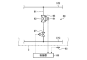
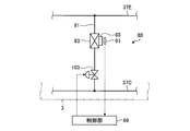
- Embodiment 1 2 to 5 are enlarged views of the cooling device in the refrigeration cycle device according to the present embodiment.
- the cooling device 80 includes a cooling branch pipe 81, a refrigerant jacket (cooler) 83, a throttle valve 87, a control unit 89, an element temperature detector 91, and an air temperature detector 93. And is comprised.
- the cooling branch pipe 81 is provided between the heat exchangers 19 and 47 to connect the outdoor heat exchanger 19 and the indoor heat exchanger 47, as shown in FIG.
- the liquid pipe 37C and the suction pipe 37E connected to the inlet side of the compressor 13 are bypassed and connected. That is, the cooling branch pipe 81 causes part of the liquid refrigerant between the heat exchangers 19 and 47 in the refrigerant circuit to bypass the inlet side of the compressor 13.
- the refrigerant jacket 83 is interposed in the cooling branch pipe 81, and is made of, for example, an aluminum block having high heat conductivity, and the cooling branch pipe 81 is provided to penetrate inside.
- the refrigerant jacket 83 is attached with a power element 85 provided in the electric circuit, and is cooled by a part of the liquid refrigerant bypassing the power element 85.
- the throttle valve 87 is provided solely upstream of the refrigerant jacket 83 of the cooling branch pipe 81.
- the throttle valve 87 is configured as an on-off valve (electromagnetic valve) that opens or closes the cooling branch pipe 81 on the upstream side of the refrigerant jacket 83.
- the control unit 89 performs opening control or closing control of the throttle valve 87.
- the control unit 89 receives the temperatures detected by the element temperature detector 91 and the air temperature detector 93, and controls the throttle valve 87 based on the inputs.
- the element temperature detector 91 detects the temperature of the power element 85.
- the element temperature detector 91 is attached to the surface of the power element 85 to detect the surface temperature of the power element 85.
- the element temperature detector 91 is attached near the power element 85 to detect the temperature emitted from the surface of the power element 85.
- the air temperature detector 93 detects the outside temperature which is the outside temperature of the outdoor unit 3 and is the ambient air temperature which the outdoor heat exchanger 19 exchanges heat with.
- the air temperature detector 93 may not be used to control the throttle valve 87 by the control unit 89.
- the control unit 89 stores in advance in a storage unit (not shown) a set temperature for opening control of the throttle valve 87 and a set temperature for closing control of the throttle valve 87.
- a set temperature for opening control of the throttle valve 87 is 50 ° C.
- the set lower limit temperature at which the throttle valve 87 is closed based on the temperature detected by the element temperature detector 91 is 45 ° C.
- the set upper limit temperature for opening control of the throttle valve 87 based on the detected temperature of the air temperature detector 93 is 35 ° C.
- the set lower limit temperature for closing control of the throttle valve 87 based on the detected temperature of the air temperature detector 93 Is 30 ° C.
- Control of the throttle valve 87 by the control unit 89 will be described.
- the controller 89 controls the valve 87 to open when the temperature detected by the element temperature detector 91 is the set upper limit temperature.
- the control unit 89 controls the throttle valve 87 to close.
- the throttle valve 87 is opened and the liquid refrigerant flows through the cooling branch pipe 81 and passes through the refrigerant jacket 83 to be a power element. It can cool 85.
- the throttle valve 87 is closed and the liquid refrigerant does not flow through the cooling branch pipe 81, so that the power element 85 is not cooled. Condensation can be prevented.
- the control unit 89 determines that the detected temperature of the element temperature detector 91 is the set upper limit temperature, or When the temperature detected by the air temperature detector 93 is the set upper limit temperature, the throttle valve 87 is controlled to open. On the other hand, when the detected temperature of the element temperature detector 91 is the set lower limit temperature and the detected temperature of the air temperature detector 93 is the set lower limit temperature, the control unit 89 controls the throttle valve 87 to close.
- the throttle valve 87 is opened and the liquid refrigerant is for cooling.
- the power element 85 can be cooled by flowing through the branch pipe 81 and passing through the refrigerant jacket 83.
- the throttle valve 87 is closed and the liquid refrigerant is the branch pipe for cooling 81 Since the power element 85 is not cooled by not passing through, it is possible to prevent the occurrence of excessive cooling and condensation.
- the compressor 13, the outdoor heat exchanger (heat source side heat exchanger) 19, the expansion valves 23, 49, and the indoor heat exchanger (use side heat exchanger) 47 have piping (Discharge piping 37A, gas piping 37B, liquid piping 37C, gas piping 37D, suction piping 37E, gas side piping 5, branch gas side piping 5A, 5B, liquid side piping 7, branch liquid side piping 7A, 7B) And a cooling branch pipe 81 for bypassing a part of the liquid refrigerant between the heat exchangers 19 and 47 in the refrigeration cycle 45 to the inlet side of the compressor 13; A refrigerant jacket (cooler) 83 for cooling the power element 85 provided in the electric circuit that is interposed in the cooling branch pipe 81 and controls the operation of the compressor 13 with a part of the liquid refrigerant, and the cooling branch pipe 81 A throttle valve 87 provided only on the upstream side of the refrigerant jacket 83, an element temperature detector
- the cooling of the power element 85 is performed based on the temperature of the power element 85, the excessive cooling of the power element 85 and the occurrence of condensation can be prevented.
- the configuration that operates to cool the power element 85 is only the throttle valve 87 provided only on the upstream side of the refrigerant jacket 83, so the configuration can be simplified, and a failure occurs. The factors can be reduced to reduce the risk of failure.
- the configuration that operates to cool the power element 85 is the throttle valve 87 provided only on the upstream side of the refrigerant jacket 83, so that the heat exchangers 19 and 47 that become condensers The deterioration of the operating efficiency can be suppressed without raising the temperature of the refrigerant at the outlet.
- the refrigeration cycle apparatus further includes an air temperature detector 93 that detects the temperature of the air around which the outdoor heat exchanger 19 exchanges heat, and the control unit 89 detects the temperature detected by the element temperature detector 91 or
- the throttle valve 87 is controlled to open based on the temperature detected by the air temperature detector 93, while the throttle valve 87 is closed to control based on the temperature detected by the element temperature detector 91 and the temperature detected by the air temperature detector 93.
- the throttle valve 87 by controlling the throttle valve 87 based on the temperature detected by the air temperature detector 93 in addition to the element temperature detector 91, the power element 85 can be reliably cooled, and the power Excessive cooling of the element 85 and the occurrence of condensation can be reliably prevented.
- the throttle valve 87 is an on-off valve.
- the configuration is simple and there are few failures, so the effect of simplifying the configuration and reducing the risk of failure occurrence can be significantly obtained.
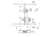
- the fixed throttle portion 95 provided in parallel with the throttle valve 87 on the upstream side of the refrigerant jacket 83 of the cooling branch pipe 81 is provided. preferable.
- the fixed throttling portion 95 is a throttling portion having a fixed amount of throttling, and is, for example, a capillary tube.
- the liquid refrigerant is allowed to flow through the cooling branch pipe 81 even in the state where the throttle valve 87 is closed. It is possible to prevent an excessive temperature rise in an electric circuit having the power element 85 or a control box or the like in which the electric circuit is contained other than the electric power element 85.
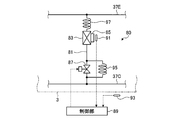
- the fixed throttling portion 97 is a throttling portion having a fixed amount of throttling, and is, for example, a capillary tube.
- the pressure on the inlet side of the compressor 13 on the downstream side of the refrigerant jacket 83 increases, and the temperature of the refrigerant jacket 83 Can prevent the occurrence of condensation.
- the effect which provided the fixed aperture part 95 can also be acquired by comprising in this way, but the fixed aperture The configuration may be such that the portion 95 is not provided.
- the fixed throttling portion 99 may be provided upstream of the refrigerant jacket 83 of the cooling branch pipe 81 and downstream of the throttle valve 87. preferable.
- the fixed throttling portion 99 is a throttling portion having a fixed amount of throttling, and is, for example, a capillary tube.
- the fixed throttling portion 99 is provided upstream of the refrigerant jacket 83 and downstream of the throttle valve 87 to enter the fixed throttle in the liquid phase, so that the flow rate is effectively appropriate. Can be adjusted.
- the pressure at the refrigerant jacket 83 can be lowered than the inlet pressure by the fixed throttling portion 99, the temperature of the refrigerant is also lowered, and a temperature difference with the power element 85 is obtained, whereby the cooling effect can be enhanced. .
- the refrigerant on the upstream side of the refrigerant jacket 83 is a liquid phase (or two phases close to the liquid phase), and the downstream side is a gas phase or two phases close to the gas phase as the refrigerant is superheated.
- the liquid phase has a large refrigerant density, and the density decreases as it becomes two phase and gas phase (if the mass is the same, the volume is larger as the density is smaller).
- FIG. 5 shows an example in which the fixed throttling portion 99 is provided together with the fixed throttling portion 95 and the fixed throttling portion 97, the effect obtained by providing the fixed throttling portion 95 and the fixed throttling portion 97 is described. However, at least one of the fixed throttling portion 95 and the fixed throttling portion 97 may not be provided.
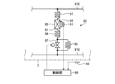
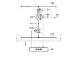
- Second Embodiment 6 to 8 are enlarged views of the cooling device in the refrigeration cycle device according to the present embodiment.
- the cooling device 80 is configured to include a cooling branch pipe 81, a refrigerant jacket (cooler) 83, a throttle valve 103, a control unit 89, and an element temperature detector 91. There is.
- the cooling branch pipe 81 is provided between the heat exchangers 19 and 47 to connect the outdoor heat exchanger 19 and the indoor heat exchanger 47, as shown in FIG.
- the liquid pipe 37C and the suction pipe 37E connected to the inlet side of the compressor 13 are bypassed and connected. That is, the cooling branch pipe 81 causes part of the liquid refrigerant between the heat exchangers 19 and 47 in the refrigerant circuit to bypass the inlet side of the compressor 13.
- the refrigerant jacket 83 is interposed in the cooling branch pipe 81, and is made of, for example, an aluminum block having high heat conductivity, and the cooling branch pipe 81 is provided to penetrate inside.
- the refrigerant jacket 83 is attached with a power element 85 provided in the electric circuit, and is cooled by a part of the liquid refrigerant bypassing the power element 85.
- the throttling valve 103 is provided solely upstream of the refrigerant jacket 83 of the cooling branch pipe 81.
- the throttle valve 103 is configured as an expansion valve whose opening degree can be adjusted on the upstream side of the refrigerant jacket 83 with respect to the cooling branch pipe 81.
- the control unit 89 performs opening control or closing control of the throttle valve 103 so as to change the opening degree.
- the control unit 89 receives the temperature detected by the element temperature detector 91, and controls the throttle valve 103 based on the input.
- the element temperature detector 91 detects the temperature of the power element 85.
- the element temperature detector 91 is attached to the surface of the power element 85 to detect the surface temperature of the power element 85.
- the element temperature detector 91 is attached near the power element 85 to detect the temperature emitted from the surface of the power element 85.
- the control unit 89 stores in advance a target temperature at which the throttle valve 103 is controlled to be opened or closed in a storage unit (not shown).
- a target temperature at which the throttle valve 103 is controlled to open and close based on the temperature detected by the element temperature detector 91 is 60.degree.
- the target temperature for opening and closing the throttle valve 103 based on the temperature detected by the air temperature detector 93 is 35 ° C.
- Control of the throttle valve 103 by the control unit 89 will be described.
- the controller 89 opens the throttle valve 103 when the temperature detected by the element temperature detector 91 exceeds the target temperature so that the temperature detected by the element temperature detector 91 becomes the target temperature. Control.
- the controller 89 controls the throttle valve 103 to close.
- the compressor 13, the outdoor heat exchanger (heat source side heat exchanger) 19, the expansion valves 23, 49, and the indoor heat exchanger (use side heat exchanger) 47 have piping (Refrigeration cycle (refrigerant circuit) 45 connected by discharge piping 37A, gas piping 37B, liquid piping 37C, gas piping 37D, suction piping 37E, gas side piping 5 and liquid side piping 7) for circulating the refrigerant, and refrigeration
- the cooling branch pipe 81 for bypassing a part of the liquid refrigerant between the heat exchangers 19 and 47 in the cycle 45 to the inlet side of the compressor 13 and the cooling branch pipe 81 operate the compressor 13.
- the refrigerant jacket (cooler) 83 for cooling the power element 85 provided in the electric circuit for controlling the liquid refrigerant with a part of the liquid refrigerant and the refrigerant jacket 83 of the cooling branch pipe 81 It comprises a throttle valve 103, the element temperature detector 91 for detecting the temperature of the power device 85, a control unit 89 for opening control or closed control throttle valve 103 based on the detected temperature of the element temperature detector 91, a.
- the cooling of the power element 85 is performed based on the temperature of the power element 85, the excessive cooling of the power element 85 and the occurrence of condensation can be prevented.
- the configuration that operates to cool the power element 85 is only the throttle valve 103 provided only on the upstream side of the refrigerant jacket 83, so the configuration can be simplified, and a failure occurs. The factors can be reduced to reduce the risk of failure.
- the throttle valve 103 is an expansion valve.
- the temperature adjustment of the power element 85 can be performed with high accuracy by using the throttle valve 103 as the expansion valve.
- the fixed throttling portion 97 is a throttling portion having a fixed amount of throttling, and is, for example, a capillary tube.
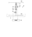
- the fixed throttling portion 99 is provided on the upstream side of the refrigerant jacket 83 of the cooling branch pipe 81 and on the downstream side of the throttle valve 103. preferable.
- the fixed throttling portion 99 is a throttling portion having a fixed amount of throttling, and is, for example, a capillary tube.
- the fixed throttling portion 99 is provided upstream of the refrigerant jacket 83 and downstream of the throttle valve 103 to enter the fixed throttle in the liquid phase, so that the flow rate is effectively appropriate. Can be adjusted.
- the pressure at the refrigerant jacket 83 can be lowered than the inlet pressure by the fixed throttling portion 99, the temperature of the refrigerant is also lowered, and a temperature difference with the power element 85 is obtained, whereby the cooling effect can be enhanced. .
- the refrigerant on the upstream side of the refrigerant jacket 83 is a liquid phase (or two phases close to the liquid phase), and the downstream side is a gas phase or two phases close to the gas phase as the refrigerant is superheated.
- the liquid phase has a large refrigerant density, and the density decreases as it becomes two phase and gas phase (if the mass is the same, the volume is larger as the density is smaller).
- FIG. 9 is a refrigerant circuit diagram of another example of the refrigeration cycle apparatus according to the present embodiment.
- the refrigeration cycle apparatus shown in FIG. 1 includes a subcooling circuit composed of a subcooling heat exchanger 27, a subcooling expansion valve 29, and a subcooling branch pipe 37F.
- the cooling branch piping 81 is closer to the indoor heat exchanger 47 and closer to the liquid-side operation valve 35 than the position where the subcooling branch piping 37F is connected in the liquid piping 37C.
- the refrigeration cycle apparatus shown in FIG. 9 does not include the subcooling heat exchanger 27, which is a subcooling circuit, the subcooling expansion valve 29, and the subcooling branch pipe 37F. It is connected to the liquid pipe 37C regardless of the situation.
- a branch pipe for supercooling that bypasses a part of the liquid refrigerant between the heat exchangers 19 and 47 in the refrigeration cycle (refrigerant circuit) 45 to the inlet side of the compressor 13 37F, a subcooling expansion valve 29 provided in the subcooling branch pipe 37F to expand a portion of the liquid refrigerant, and a downstream side of the subcooling expansion valve 29 of the subcooling branch pipe 37F
- the cooling branch pipe 81 includes a subcooling circuit including a subcooling heat exchanger 27 that exchanges heat between the liquid refrigerant that has passed through the cooling expansion valve 29 and the liquid refrigerant of the refrigeration cycle 45, and the cooling branch pipe 81 is indoors than the subcooling circuit. It is provided in the position which introduce
- the refrigerant of the refrigerant jacket 83 is in a state of being subcooled.
- a refrigerant with a large amount of subcooling has a lower enthalpy state (more cold state) as a refrigerant than a state with a low degree of subcooling, and therefore the cooling effect is enhanced by introducing it into the refrigerant jacket 83 .
Abstract
La présente invention concerne un dispositif à cycle frigorifique doté : d'un tuyau piqué (81) destiné au refroidissement qui forme une dérivation permettant d'amener une partie du fluide frigorigène, situé entre un échangeur thermique extérieur et un échangeur thermique intérieur dans le cadre d'un cycle frigorifique (45), à s'écouler vers le côté d'admission d'un compresseur; d'une chemise de refroidissement (83) qui refroidit un élément de puissance (85) placé dans un circuit électrique afin de commander le fonctionnement du compresseur (13), en utilisant une partie du fluide frigorigène et est placé le long du tuyau piqué (81) destiné au refroidissement; d'une soupape d'étranglement (87) placée uniquement du côté amont de la chemise de refroidissement (83) dans le tuyau piqué (81) destiné au refroidissement; d'un capteur de température d'élément (91) destiné à détecter la température de l'élément de puissance (85); et d'une unité de commande (89) destinée à exécuter une commande d'ouverture ou une commande de fermeture de la soupape d'étranglement (87) sur la base de la température détectée du capteur de température d'élément (91). Par conséquent, il est possible d'empêcher un refroidissement excessif d'un élément de puissance et d'éviter la formation de condensation sur celui-ci, tout en en simplifiant sa configuration et en éliminant une diminution de son efficacité de fonctionnement.
Priority Applications (2)
| Application Number | Priority Date | Filing Date | Title |
|---|---|---|---|
| CN201680069762.4A CN108291746A (zh) | 2016-02-08 | 2016-12-13 | 制冷循环装置 |
| EP16889944.1A EP3370014A4 (fr) | 2016-02-08 | 2016-12-13 | Dispositif à cycle frigorifique |
Applications Claiming Priority (2)
| Application Number | Priority Date | Filing Date | Title |
|---|---|---|---|
| JP2016-022037 | 2016-02-08 | ||
| JP2016022037A JP2017141987A (ja) | 2016-02-08 | 2016-02-08 | 冷凍サイクル装置 |
Publications (1)
| Publication Number | Publication Date |
|---|---|
| WO2017138243A1 true WO2017138243A1 (fr) | 2017-08-17 |
Family
ID=59563732
Family Applications (1)
| Application Number | Title | Priority Date | Filing Date |
|---|---|---|---|
| PCT/JP2016/087008 WO2017138243A1 (fr) | 2016-02-08 | 2016-12-13 | Dispositif à cycle frigorifique |
Country Status (4)
| Country | Link |
|---|---|
| EP (1) | EP3370014A4 (fr) |
| JP (1) | JP2017141987A (fr) |
| CN (1) | CN108291746A (fr) |
| WO (1) | WO2017138243A1 (fr) |
Families Citing this family (1)
| Publication number | Priority date | Publication date | Assignee | Title |
|---|---|---|---|---|
| CN108489069B (zh) * | 2018-01-31 | 2020-08-18 | 青岛海尔空调电子有限公司 | 一种空调散热结构控制方法及系统 |
Citations (11)
| Publication number | Priority date | Publication date | Assignee | Title |
|---|---|---|---|---|
| JPS5650966U (fr) * | 1979-09-26 | 1981-05-06 | ||
| JPS6176267U (fr) * | 1984-10-25 | 1986-05-22 | ||
| JPS61133770U (fr) * | 1985-02-08 | 1986-08-20 | ||
| JPH06159738A (ja) * | 1992-11-25 | 1994-06-07 | Daikin Ind Ltd | 空気調和機の発熱素子の冷却装置 |
| JPH08189719A (ja) * | 1995-01-12 | 1996-07-23 | Mitsubishi Electric Corp | 空気調和装置 |
| JP2005207719A (ja) * | 2003-12-24 | 2005-08-04 | Samsung Electronics Co Ltd | 空気調和機 |
| JP2008057875A (ja) * | 2006-08-31 | 2008-03-13 | Mitsubishi Electric Corp | 冷凍サイクル装置 |
| JP2008057856A (ja) * | 2006-08-31 | 2008-03-13 | Matsushita Electric Ind Co Ltd | 空気調和機 |
| JP2009198081A (ja) * | 2008-02-21 | 2009-09-03 | Daikin Ind Ltd | 冷凍装置 |
| JP2010266132A (ja) * | 2009-05-15 | 2010-11-25 | Mitsubishi Heavy Ind Ltd | インバータ冷却装置およびインバータ冷却方法ならびに冷凍機 |
| JP2014129960A (ja) * | 2012-12-28 | 2014-07-10 | Daikin Ind Ltd | 冷凍装置 |
Family Cites Families (5)
| Publication number | Priority date | Publication date | Assignee | Title |
|---|---|---|---|---|
| JP2006183950A (ja) * | 2004-12-28 | 2006-07-13 | Sanyo Electric Co Ltd | 冷凍装置及び冷蔵庫 |
| JP5398159B2 (ja) * | 2008-03-28 | 2014-01-29 | 三菱重工業株式会社 | マルチ形空気調和機の油戻し運転方法およびマルチ形空気調和機 |
| CN102667368B (zh) * | 2009-12-22 | 2015-01-07 | 大金工业株式会社 | 制冷装置 |
| JP2011133133A (ja) * | 2009-12-22 | 2011-07-07 | Daikin Industries Ltd | 冷凍装置 |
| CN203518310U (zh) * | 2013-09-17 | 2014-04-02 | 珠海格力电器股份有限公司 | 发热功率器件冷却系统 |
-
2016
- 2016-02-08 JP JP2016022037A patent/JP2017141987A/ja active Pending
- 2016-12-13 WO PCT/JP2016/087008 patent/WO2017138243A1/fr active Application Filing
- 2016-12-13 CN CN201680069762.4A patent/CN108291746A/zh active Pending
- 2016-12-13 EP EP16889944.1A patent/EP3370014A4/fr not_active Withdrawn
Patent Citations (11)
| Publication number | Priority date | Publication date | Assignee | Title |
|---|---|---|---|---|
| JPS5650966U (fr) * | 1979-09-26 | 1981-05-06 | ||
| JPS6176267U (fr) * | 1984-10-25 | 1986-05-22 | ||
| JPS61133770U (fr) * | 1985-02-08 | 1986-08-20 | ||
| JPH06159738A (ja) * | 1992-11-25 | 1994-06-07 | Daikin Ind Ltd | 空気調和機の発熱素子の冷却装置 |
| JPH08189719A (ja) * | 1995-01-12 | 1996-07-23 | Mitsubishi Electric Corp | 空気調和装置 |
| JP2005207719A (ja) * | 2003-12-24 | 2005-08-04 | Samsung Electronics Co Ltd | 空気調和機 |
| JP2008057875A (ja) * | 2006-08-31 | 2008-03-13 | Mitsubishi Electric Corp | 冷凍サイクル装置 |
| JP2008057856A (ja) * | 2006-08-31 | 2008-03-13 | Matsushita Electric Ind Co Ltd | 空気調和機 |
| JP2009198081A (ja) * | 2008-02-21 | 2009-09-03 | Daikin Ind Ltd | 冷凍装置 |
| JP2010266132A (ja) * | 2009-05-15 | 2010-11-25 | Mitsubishi Heavy Ind Ltd | インバータ冷却装置およびインバータ冷却方法ならびに冷凍機 |
| JP2014129960A (ja) * | 2012-12-28 | 2014-07-10 | Daikin Ind Ltd | 冷凍装置 |
Non-Patent Citations (1)
| Title |
|---|
| See also references of EP3370014A4 * |
Also Published As
| Publication number | Publication date |
|---|---|
| EP3370014A4 (fr) | 2018-12-05 |
| EP3370014A1 (fr) | 2018-09-05 |
| JP2017141987A (ja) | 2017-08-17 |
| CN108291746A (zh) | 2018-07-17 |
Similar Documents
| Publication | Publication Date | Title |
|---|---|---|
| JP5855312B2 (ja) | 空気調和装置 | |
| JP6005255B2 (ja) | 空気調和装置 | |
| JP5634502B2 (ja) | 空調給湯複合システム | |
| JP5992089B2 (ja) | 空気調和装置 | |
| JP6479162B2 (ja) | 空気調和装置 | |
| JP5847366B1 (ja) | 空気調和装置 | |
| JP5968519B2 (ja) | 空気調和装置 | |
| US20100180612A1 (en) | Refrigeration device | |
| US20110036119A1 (en) | Refrigeration apparatus | |
| JPWO2017203606A1 (ja) | 空気調和装置 | |
| US11384965B2 (en) | Refrigeration cycle apparatus performing a refrigerant circulation operation using a liquid pump | |
| JP6033297B2 (ja) | 空気調和装置 | |
| JP6038382B2 (ja) | 空気調和装置 | |
| JP6067178B2 (ja) | 熱源側ユニット及び空気調和装置 | |
| JP2017161182A (ja) | ヒートポンプ装置 | |
| KR102082881B1 (ko) | 냉난방 동시형 멀티 공기조화기 | |
| JP6017048B2 (ja) | 空気調和装置 | |
| JP6598882B2 (ja) | 冷凍サイクル装置 | |
| JP5872052B2 (ja) | 空気調和装置 | |
| JP6758506B2 (ja) | 空気調和装置 | |
| WO2017138243A1 (fr) | Dispositif à cycle frigorifique | |
| JP2015152270A (ja) | 冷凍サイクル装置 | |
| JPWO2020240732A1 (ja) | 冷凍サイクル装置 | |
| JP2010203621A (ja) | 冷凍装置 |
Legal Events
| Date | Code | Title | Description |
|---|---|---|---|
| 121 | Ep: the epo has been informed by wipo that ep was designated in this application |
Ref document number: 16889944 Country of ref document: EP Kind code of ref document: A1 |
|
| WWE | Wipo information: entry into national phase |
Ref document number: 2016889944 Country of ref document: EP |
|
| NENP | Non-entry into the national phase |
Ref country code: DE |