WO2017135360A1 - 開閉駆動装置 - Google Patents
開閉駆動装置 Download PDFInfo
- Publication number
- WO2017135360A1 WO2017135360A1 PCT/JP2017/003735 JP2017003735W WO2017135360A1 WO 2017135360 A1 WO2017135360 A1 WO 2017135360A1 JP 2017003735 W JP2017003735 W JP 2017003735W WO 2017135360 A1 WO2017135360 A1 WO 2017135360A1
- Authority
- WO
- WIPO (PCT)
- Prior art keywords
- opening
- closing
- motor
- closing member
- stopped
- Prior art date
- Legal status (The legal status is an assumption and is not a legal conclusion. Google has not performed a legal analysis and makes no representation as to the accuracy of the status listed.)
- Ceased
Links
Images


Classifications
-
- B—PERFORMING OPERATIONS; TRANSPORTING
- B60—VEHICLES IN GENERAL
- B60J—WINDOWS, WINDSCREENS, NON-FIXED ROOFS, DOORS, OR SIMILAR DEVICES FOR VEHICLES; REMOVABLE EXTERNAL PROTECTIVE COVERINGS SPECIALLY ADAPTED FOR VEHICLES
- B60J1/00—Windows; Windscreens; Accessories therefor
- B60J1/08—Windows; Windscreens; Accessories therefor arranged at vehicle sides
- B60J1/12—Windows; Windscreens; Accessories therefor arranged at vehicle sides adjustable
- B60J1/16—Windows; Windscreens; Accessories therefor arranged at vehicle sides adjustable slidable
- B60J1/17—Windows; Windscreens; Accessories therefor arranged at vehicle sides adjustable slidable vertically
-
- E—FIXED CONSTRUCTIONS
- E05—LOCKS; KEYS; WINDOW OR DOOR FITTINGS; SAFES
- E05F—DEVICES FOR MOVING WINGS INTO OPEN OR CLOSED POSITION; CHECKS FOR WINGS; WING FITTINGS NOT OTHERWISE PROVIDED FOR, CONCERNED WITH THE FUNCTIONING OF THE WING
- E05F15/00—Power-operated mechanisms for wings
- E05F15/60—Power-operated mechanisms for wings using electrical actuators
- E05F15/603—Power-operated mechanisms for wings using electrical actuators using rotary electromotors
- E05F15/665—Power-operated mechanisms for wings using electrical actuators using rotary electromotors for vertically-sliding wings
- E05F15/689—Power-operated mechanisms for wings using electrical actuators using rotary electromotors for vertically-sliding wings specially adapted for vehicle windows
-
- E—FIXED CONSTRUCTIONS
- E05—LOCKS; KEYS; WINDOW OR DOOR FITTINGS; SAFES
- E05F—DEVICES FOR MOVING WINGS INTO OPEN OR CLOSED POSITION; CHECKS FOR WINGS; WING FITTINGS NOT OTHERWISE PROVIDED FOR, CONCERNED WITH THE FUNCTIONING OF THE WING
- E05F15/00—Power-operated mechanisms for wings
- E05F15/60—Power-operated mechanisms for wings using electrical actuators
- E05F15/603—Power-operated mechanisms for wings using electrical actuators using rotary electromotors
- E05F15/665—Power-operated mechanisms for wings using electrical actuators using rotary electromotors for vertically-sliding wings
- E05F15/689—Power-operated mechanisms for wings using electrical actuators using rotary electromotors for vertically-sliding wings specially adapted for vehicle windows
- E05F15/695—Control circuits therefor
-
- E—FIXED CONSTRUCTIONS
- E05—LOCKS; KEYS; WINDOW OR DOOR FITTINGS; SAFES
- E05F—DEVICES FOR MOVING WINGS INTO OPEN OR CLOSED POSITION; CHECKS FOR WINGS; WING FITTINGS NOT OTHERWISE PROVIDED FOR, CONCERNED WITH THE FUNCTIONING OF THE WING
- E05F15/00—Power-operated mechanisms for wings
- E05F15/40—Safety devices, e.g. detection of obstructions or end positions
- E05F15/41—Detection by monitoring transmitted force or torque; Safety couplings with activation dependent upon torque or force, e.g. slip couplings
-
- E—FIXED CONSTRUCTIONS
- E05—LOCKS; KEYS; WINDOW OR DOOR FITTINGS; SAFES
- E05Y—INDEXING SCHEME ASSOCIATED WITH SUBCLASSES E05D AND E05F, RELATING TO CONSTRUCTION ELEMENTS, ELECTRIC CONTROL, POWER SUPPLY, POWER SIGNAL OR TRANSMISSION, USER INTERFACES, MOUNTING OR COUPLING, DETAILS, ACCESSORIES, AUXILIARY OPERATIONS NOT OTHERWISE PROVIDED FOR, APPLICATION THEREOF
- E05Y2400/00—Electronic control; Electrical power; Power supply; Power or signal transmission; User interfaces
- E05Y2400/10—Electronic control
- E05Y2400/50—Fault detection
-
- E—FIXED CONSTRUCTIONS
- E05—LOCKS; KEYS; WINDOW OR DOOR FITTINGS; SAFES
- E05Y—INDEXING SCHEME ASSOCIATED WITH SUBCLASSES E05D AND E05F, RELATING TO CONSTRUCTION ELEMENTS, ELECTRIC CONTROL, POWER SUPPLY, POWER SIGNAL OR TRANSMISSION, USER INTERFACES, MOUNTING OR COUPLING, DETAILS, ACCESSORIES, AUXILIARY OPERATIONS NOT OTHERWISE PROVIDED FOR, APPLICATION THEREOF
- E05Y2400/00—Electronic control; Electrical power; Power supply; Power or signal transmission; User interfaces
- E05Y2400/10—Electronic control
- E05Y2400/52—Safety arrangements associated with the wing motor
- E05Y2400/53—Wing impact prevention or reduction
- E05Y2400/54—Obstruction or resistance detection
-
- E—FIXED CONSTRUCTIONS
- E05—LOCKS; KEYS; WINDOW OR DOOR FITTINGS; SAFES
- E05Y—INDEXING SCHEME ASSOCIATED WITH SUBCLASSES E05D AND E05F, RELATING TO CONSTRUCTION ELEMENTS, ELECTRIC CONTROL, POWER SUPPLY, POWER SIGNAL OR TRANSMISSION, USER INTERFACES, MOUNTING OR COUPLING, DETAILS, ACCESSORIES, AUXILIARY OPERATIONS NOT OTHERWISE PROVIDED FOR, APPLICATION THEREOF
- E05Y2900/00—Application of doors, windows, wings or fittings thereof
- E05Y2900/50—Application of doors, windows, wings or fittings thereof for vehicles
- E05Y2900/53—Type of wing
- E05Y2900/55—Windows
-
- H—ELECTRICITY
- H02—GENERATION; CONVERSION OR DISTRIBUTION OF ELECTRIC POWER
- H02H—EMERGENCY PROTECTIVE CIRCUIT ARRANGEMENTS
- H02H7/00—Emergency protective circuit arrangements specially adapted for specific types of electric machines or apparatus or for sectionalised protection of cable or line systems, and effecting automatic switching in the event of an undesired change from normal working conditions
- H02H7/08—Emergency protective circuit arrangements specially adapted for specific types of electric machines or apparatus or for sectionalised protection of cable or line systems, and effecting automatic switching in the event of an undesired change from normal working conditions for dynamo-electric motors
- H02H7/085—Emergency protective circuit arrangements specially adapted for specific types of electric machines or apparatus or for sectionalised protection of cable or line systems, and effecting automatic switching in the event of an undesired change from normal working conditions for dynamo-electric motors against excessive load
- H02H7/0851—Emergency protective circuit arrangements specially adapted for specific types of electric machines or apparatus or for sectionalised protection of cable or line systems, and effecting automatic switching in the event of an undesired change from normal working conditions for dynamo-electric motors against excessive load for motors actuating a movable member between two end positions, e.g. detecting an end position or obstruction by overload signal
Definitions
- the present invention relates to an opening / closing drive device.
- an opening / closing drive device used for a vehicle power window device or the like there is one provided with a motor having a lowering prevention mechanism that prevents the window glass from lowering (downward movement) (see, for example, Patent Document 1).
- This motor lowering prevention mechanism utilizes frictional resistance caused when the axial end of the rotating shaft is pressed and brought into contact with the braking member on the housing side when the window glass is going to descend.
- the frictional resistance needs to be increased in order to prevent the opening / closing member from moving down due to vibration or the like.
- Increasing the frictional resistance has a problem that the startability of the motor is deteriorated. This makes it necessary to increase the torque generated at the time of starting, and as a result, increases the size of the motor.
- An object of the present invention is to provide an opening / closing drive device capable of improving the startability of a motor while avoiding that the opening / closing member remains lowered.
- the opening / closing drive device drives an opening / closing member that can move up and down.
- the opening / closing drive device includes a motor, a position detection sensor capable of detecting the position of the opening / closing member, and a control unit.
- the control unit determines that the opening / closing member has moved down to a position equal to or lower than a preset threshold value based on a signal from the position detection sensor in a state where the motor is not driven, the opening / closing member The motor is driven to move the motor up.
- the opening / closing drive device drives an opening / closing member that can move up and down.
- the opening / closing drive device includes a motor, a position detection sensor capable of detecting the position of the opening / closing member, and a control unit.
- the control unit determines that the opening / closing member has moved down to a position separated by a predetermined threshold or more based on a signal from the position detection sensor without driving the motor, the opening / closing is performed.
- the motor is driven to move the member upward.
- the opening / closing drive device drives an opening / closing member that can move up and down.
- the opening / closing drive device includes a motor, a position detection sensor that can detect the position of the opening / closing member, and a control unit that controls driving of the motor.
- the control unit determines a downward movement amount of the opening / closing member based on a signal from the position detection sensor, or determines a position after the downward movement of the opening / closing member based on a signal from the position detection sensor. It is configured.
- the control unit when the motor is not driven, when the amount of downward movement exceeds a preset threshold, or when the position after the downward movement of the opening and closing member exceeds an arbitrary position, The motor is driven to move the opening / closing member upward.
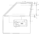
- the schematic block diagram of the power window apparatus of this indication. 1 is a schematic configuration diagram of an opening / closing drive device according to an embodiment of the present disclosure.
- (A) And (b) is a schematic cross section for demonstrating the obstruction
- a window glass 2 as an opening / closing member is provided on the vehicle door 1 so as to be movable up and down, and a motor M in an opening / closing drive device 3 is connected to the window glass 2 via a regulator (not shown).
- a regulator not shown
- the motor M includes a rotating shaft 5 to which the armature 4 is fixed, a worm 6 that rotates integrally with the rotating shaft 5, and a worm wheel 7 that meshes with the worm 6.
- the window glass 2 is connected to an output shaft 8 that rotates integrally with the worm wheel 7 via a regulator or the like.
- the housing 9 that houses the motor M, when the window glass 2 is to be lowered (downwardly moved), one end in the axial direction of the rotating shaft 5 comes into contact with a position facing the one end in the axial direction of the rotating shaft 5.
- a braking member 9a is provided.
- a Hall IC 11 as a position detection sensor capable of detecting the position of the window glass 2 is provided in the vicinity of the sensor magnet 10 fixed to the rotating shaft 5.
- a control unit 12 made of an IC chip or the like is provided in the housing 9 of the opening / closing drive device 3.
- the control unit 12 is realized by, for example, a circuit, that is, one or more dedicated hardware circuits such as an ASIC, one or more processing circuits that operate according to a computer program (software), or a combination of both. Can do.
- the processing circuit includes a CPU and a memory (such as a ROM and a RAM) that stores a program executed by the CPU.
- Memory or computer readable media includes any available media that can be accessed by a general purpose or special purpose computer.
- the Hall IC 11 outputs a pulse signal corresponding to the change in the magnetic flux of the sensor magnet 10 to the control unit 12 when the rotating shaft 5 rotates.
- This pulse signal is output, for example, every time the window glass 2 moves up and down 2 mm.
- the control unit 12 drives the motor M to move the window glass 2 up and down according to the operation. Further, the control unit 12 sets the threshold value of the window glass 2 that is set in advance on the basis of the pulse signal from the Hall IC 11 when the position of the window glass 2 is moved down while the motor M is not driven. If it is determined that the window glass 2 has moved down to a position separated by more than the amount of movement), the motor M is driven to move the window glass 2 upward.
- control unit 12 of the present embodiment sets the threshold value (downward movement amount) according to the position of the window glass 2 when the motor M is stopped. Specifically, the control unit 12 sets the threshold value (downward movement amount) according to which area the window glass 2 is located in the window area (an area including the vehicle window and its vertically adjacent portion). To do.
- the “position of the window glass 2” is preferably the position of the upper end of the window glass 2.
- the threshold value is set to a small downward movement amount (first downward movement amount) when the position of the window glass 2 when the motor M is stopped is within the close-close area A.
- the threshold value is set to a large downward movement amount (second downward movement amount) when the position of the window glass 2 when the motor M is stopped is in the opening / closing intermediate area B below the closing vicinity area A. Is done.
- occlusion vicinity area A said here is set to the area from the position where opening becomes a fully-closed state by the window glass 2 to a position 5 cm lower, for example.
- the small downward movement amount is set to 6 mm (3 pulses), for example, and the large downward movement amount is set to 14 mm (7 pulses), for example.
- the threshold value is set to a small downward movement amount (first downward movement amount) when the position of the window glass 2 when the motor M is stopped is in the fully open vicinity area C.
- the threshold value is set to a large downward movement amount (second downward movement amount) when the position of the window glass 2 when the motor M is stopped is in the opening / closing intermediate area B above the fully open vicinity area C.
- the fully open vicinity area C referred to here is set, for example, to an area from the position at which the opening is fully opened by the window glass 2 to a position 5 cm higher, and the small downward movement amount is set to 6 mm (for 3 pulses), for example.
- the large downward movement amount is set to 14 mm (for 3 pulses), for example.
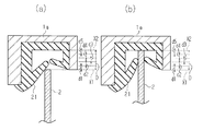
- the upper end door frame 1a is provided with a glass run 21 as an upper end frame side member.
- a position where the upper end of the window glass 2 reaches the glass run 21 from below (see FIG. 3A) is defined as a closed arrival position X1.
- a position above the closing arrival position X1 is defined as the upper movement limit position X2.
- the window glass 2 is in the fully closed state at the closing arrival position X1, and can be moved up to the upper movement limit position X2 while maintaining the fully closed state (see FIG. 3B).
- the glass run 21 is made of an elastic member, and in the fully closed state, ensures a sealing property inside and outside the vehicle and absorbs an impact when the window glass 2 reaches the upper movement limit position X2.
- the threshold value is A downward movement amount corresponding to a position equal to or higher than the closing arrival position X1 is set. That is, when the upper end of the window glass 2 is located in the closing movable area D, the threshold value is greater than zero and is between the position of the window glass 2 when the motor M is stopped and the closing arrival position X1. Set to the amount of downward movement below the distance. In the present embodiment, this threshold value is set in a plurality of stages in the closed movable area D, and the threshold value is larger as the position of the window glass 2 when the motor M is stopped is closer to the upper movement limit position X2.
- the threshold value of the present embodiment is divided into five stages according to the number of rises of the pulse signal output from the Hall IC 11 between the closing arrival position X1 and the upper limit position X2. It is divided (see the broken line in FIG. 3).
- the threshold value is divided into first to fifth areas d1 to d5 in order from the lower position of the window glass 2 when the motor M is stopped.
- the threshold corresponds to 5 pulses (5 rises of the pulse signal).
- the amount of downward movement is set.
- the downward movement amount corresponding to 4 pulses in the third area d3, the downward movement amount corresponding to 3 pulses, in the second area d2, the downward movement amount corresponding to 2 pulses, and in the first area d1, equivalent to 1 pulse.
- the amount of downward motion to be set is set.
- the control unit 12 does not drive the motor M and the window glass 2 , The motor M is driven to move the window glass 2 upward. Further, for example, when the position of the window glass 2 when the motor M is stopped is in the third area d3 in the closing movable area D, the control unit 12 does not drive the motor M and the window glass 2 , The motor M is driven to move the window glass 2 upward.
- the control unit 12 does not drive the motor M and the window glass 2 , The motor M is driven to move the window glass 2 upward.
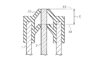
- the vehicle door 1 is provided with a belt molding 22 as a lower end frame side member.
- the position where the upper end of the window glass 2 has reached the belt molding 22 from above is defined as a fully open arrival position X3.
- the window glass 2 is in a fully opened state at the fully opened arrival position X3, and can be moved down to the lower limit position X4 while maintaining the fully opened state.
- the belt molding 22 is made of an elastic member, and is slidably contacted with the window glass 2 to reduce intrusion of raindrops and the like into the vehicle door 1.
- the threshold value is Not set. If the threshold value is not set here, the motor M is not driven no matter how much the position of the window glass 2 is moved in a state where the motor M is not driven (the window glass 2 is moved upward). It does not move.
- the area where the threshold value is not set may be an area larger than the fully open movable area E.
- control unit 12 of the present embodiment determines that the window glass 2 has moved down to a position separated by the threshold value (downward movement amount) or more without driving the motor M, the motor M is stopped. The motor M is driven to move the window glass 2 up to the position of the window glass 2 at that time.
- control unit 12 performs the following processing based on a pulse signal output from the Hall IC 11 when the window glass 2 is moved down by, for example, vibration during traveling.
- step S1 the control unit 12 confirms the position of the window glass 2 when the motor M is stopped (by the control unit 12) from the pulse signal input so far, and proceeds to step S2.
- step S2 the control unit 12 sets the threshold value according to the position (area) of the window glass 2 when the motor M is stopped by the control unit 12, and proceeds to step S3.
- the threshold value is set to a small downward movement amount (for example, 6 mm and 3 pulses).
- step S3 the control unit 12 determines whether or not the motor M is driven (the window glass 2 is moved downward). If it is determined that the motor M is driven, the control unit 12 proceeds to step S4 and continues to drive. If it is determined that it is not driven, the process proceeds to step S5. That is, in step S3, it is determined whether or not the window glass 2 is moving down arbitrarily due to vibration during traveling.
- step S5 the control unit 12 determines whether or not the window glass 2 has moved down to a position separated by a set threshold value or more. If the control unit 12 determines that the window glass 2 has not moved down to a position separated by a threshold value or more, the control unit 12 repeats Step S3 and Step S5, and if determined that the window glass 2 has moved down to a position separated by a threshold value or more, The process proceeds to S6.
- step S6 the control unit 12 drives the motor M to move the window glass 2 up to the position of the window glass 2 when the motor M is stopped by the control unit 12, and ends the process. Therefore, it is prevented that the window glass 2 is returned to the position when the motor M is stopped (the position before the motor M is moved down due to vibration or the like) and remains moved down.
- the control unit 12 determines that the window glass 2 has moved down to a preset threshold value or less based on the pulse signal from the Hall IC 11 in a state where the motor M is not driven, the window glass 2
- the motor M is configured to be driven to move the motor up.
- the control unit 12 determines that the window glass 2 has moved down to a position separated by a predetermined threshold or more based on the pulse signal from the Hall IC 11 in a state where the motor M is not driven
- the motor M is driven to move the window glass 2 upward. Therefore, for example, even if the window glass 2 moves down due to vibration or the like, the position of the window glass 2 can be returned to the upper position.
- the frictional resistance of the motor M that is, the frictional resistance between the axial end of the rotating shaft 5 and the braking member 9a for preventing the window glass 2 from moving down is reduced. Therefore, the startability of the motor M can be improved. As a result, for example, the torque at the time of starting the motor M can be reduced, and the motor M can be reduced in size.
- the control unit 12 sets a threshold value according to the position of the window glass 2 when the motor M is stopped. Therefore, for example, the window glass 2 can be moved up as necessary. For example, if the user is in a position where it is difficult for the user to feel uncomfortable even if the window glass 2 is slightly moved down, it is possible to reduce power consumption by preventing the window glass 2 from moving up even if the window glass 2 is slightly moved down.
- the threshold value is set to a small downward movement amount when the position of the window glass 2 when the motor M is stopped is within the close-close area A. For this reason, when the slightly opened opening is slightly increased, the position of the window glass 2 is returned to the upper position, and for example, it is difficult for the user to feel uncomfortable.
- the threshold value is set to a large downward movement amount when the position of the window glass 2 when the motor M is stopped is in the open / close intermediate area B below the close proximity area A. Therefore, even if the opening opened to the intermediate position becomes slightly large, the motor M is not driven and low power consumption can be achieved. This makes it possible to reduce power consumption while making it difficult for the user to feel uncomfortable.
- the threshold value is set to a small downward movement amount when the position of the window glass 2 when the motor M is stopped is in the fully open vicinity area C. Therefore, if the opening slightly closed by the window glass 2 becomes slightly large, the position of the window glass 2 is returned to the upper position, and for example, it is difficult for the user to feel uncomfortable. Further, the threshold value is set to a large downward movement amount when the position of the window glass 2 when the motor M is stopped is in the open / close intermediate area B above the fully open vicinity area C. Therefore, even if the opening opened to the intermediate position becomes slightly large, the motor M is not driven and low power consumption can be achieved. This makes it possible to reduce power consumption while making it difficult for the user to feel uncomfortable.
- the threshold value reaches closing. It is set to a position equal to or higher than position X1. Therefore, when the window glass 2 moves down to a threshold value or less corresponding to a position equal to or higher than the closing arrival position X1 (the position of the closing arrival position X1 in this embodiment), the window glass 2 is driven upward. In other words, when the upper end of the window glass 2 is located in the closing movable area D, the threshold value is greater than zero and between the position of the window glass 2 when the motor M is stopped and the closing arrival position X1. It is set to the amount of downward movement below the distance.
- the motor M is stopped in a state where the upper end of the window glass 2 is located in the closing movable area D, and then the window glass 2 is moved down to a position below the closing arrival position X1 (when the motor M is stopped).
- the control unit 12 drives the motor M to move the window glass 2 up.
- the position of the window glass 2 is prevented from being stopped from the closed movable area D below the closed arrival position X1. Therefore, it is prevented that a slight gap is generated from the closed state.
- the threshold value is set in a plurality of stages. As the position of the window glass 2 when the motor M is stopped is closer to the upper movement limit position X2, the threshold value is set to a larger downward movement amount. Therefore, it can suppress that the window glass 2 drives upwards more than necessary. That is, for example, the window glass 2 is kept fully closed even if the window glass 2 moves slightly downward (for example, two pulses from within the fourth area d4) from a position close to the upper movement limit position X2. The power consumption can be reduced by not driving the motor M.
- control part 12 set the threshold value according to the position where the motor M was stopped (of the window glass 2), it is not limited to this, For example, always a fixed threshold value It may be a value.
- the threshold value is set to a small downward movement amount when the position of the window glass 2 when the motor M is stopped is in the close proximity area A and the fully open proximity area C, and the open / close middle
- the amount of downward movement may be set larger in the vicinity of the fully open area C than in the close proximity area A as in the open / close intermediate area B.
- the threshold value is
- the downward movement amount corresponding to a position equal to or higher than the closing arrival position X1 is set, the present invention is not limited to this, and an arbitrary downward movement amount may be set even within the closing movable area D.
- the threshold value when the position of the window glass 2 when the motor M is stopped is within the closed movable area D, the threshold value is set in a plurality of stages. As the position of the window glass 2 when the motor M is stopped is closer to the upper movement limit position X2, the threshold value is set to a larger downward movement amount.
- control may be performed such that when it moves down to the closing arrival position X1 or lower, it is moved up.
- the window glass 2 has been moved down by three pulses or moved down to a position below the closing arrival position X1.
- the threshold value I when the position of the window glass 2 when the motor M is stopped is within the fully open movable area E set between the fully open arrival position X3 and the downward movement limit position X4, the threshold value Is not set, but is not limited to this, and may be set to an arbitrary value.
- the controller 12 moves the window glass 2 up to the position of the window glass 2 when the motor M is stopped.
- the present invention is not limited to this. If it is close to the position of the window glass 2 when stopped, the amount to be moved up may be changed.
- the Hall IC 11 is used.
- the position of the window glass 2 (and corresponding information) may be changed to another position detection sensor as long as it can be detected.
- the opening / closing drive device 3 is configured such that the motor M, the Hall IC 11 and the control unit 12 are accommodated in the single housing 9, but the present invention is not limited thereto, and the motor M and the Hall IC 11 It is good also as an opening-and-closing drive device which consists of the motor apparatus provided with and the control part 12 which was provided separately from the motor apparatus and was connected to the motor apparatus with the wiring.
- the present invention is embodied in the power window device that moves the window glass 2 up and down, but may be embodied in other opening / closing drive devices that move the opening / closing member other than the window glass 2 up and down.
- SYMBOLS 2 Window glass (opening-closing member), 11 ... Hall IC (position detection sensor), 12 ... Control part, 21 ... Glass run (upper frame side member), 22 ... Belt molding (lower end frame side member), A ... Near blockage Area, B: Open / close intermediate area, C: Fully open area, D: Closed movable area, E ... Fully open movable area, M ... Motor, X1 ... Closed reach position, X2 ... Upper movement limit position, X3 ... Full open reach position, X4 ... Downward movement limit area.
Landscapes
- Engineering & Computer Science (AREA)
- Mechanical Engineering (AREA)
- Power-Operated Mechanisms For Wings (AREA)
- Window Of Vehicle (AREA)
Abstract
開閉駆動装置は、上下動可能な開閉部材を駆動させる。開閉駆動装置は、モータと、開閉部材の位置を検出可能な位置検出センサと、制御部とを含む。制御部は、モータを駆動させていない状態で、位置検出センサからの信号に基づいて開閉部材が予め設定されたしきい値以下の位置まで下動したと判定すると、開閉部材を上動させるべくモータを駆動させるように構成されている。
Description
本発明は、開閉駆動装置に関するものである。
車両用パワーウィンドウ装置等に利用される開閉駆動装置としては、ウィンドウガラスの下降(下動)を防止する下降防止機構を有するモータを備えたものがある(例えば、特許文献1参照)。
このモータの下降防止機構は、ウィンドウガラスが下降しようとすると回転軸の軸方向一端部がハウジング側の制動部材に押圧及び接触されることによる摩擦抵抗を利用している。
しかしながら、上記のような開閉駆動装置では、例えば、振動等によっても開閉部材が下動してしまわないようにするために前記摩擦抵抗を大きくする必要がある。摩擦抵抗を大きくすることで、モータの起動性が悪くなるという問題があった。このことは、起動時に発生させるトルクを大きくする必要を生じさせ、ひいてはモータを大型化させる原因となる。
本発明の目的は、開閉部材が下動してしまったままとなることを避けつつモータの起動性を良好とすることができる開閉駆動装置を提供することにある。
上記目的を達成するため、本開示の第1の態様にかかる開閉駆動装置は、上下動可能な開閉部材を駆動させる。前記開閉駆動装置は、モータと、前記開閉部材の位置を検出可能な位置検出センサと、制御部とを含む。前記制御部は、前記モータを駆動させていない状態で、前記位置検出センサからの信号に基づいて前記開閉部材が予め設定されたしきい値以下の位置まで下動したと判定すると、前記開閉部材を上動させるべく前記モータを駆動させるように構成されている。
本開示の第2の態様にかかる開閉駆動装置は、上下動可能な開閉部材を駆動させる。前記開閉駆動装置は、モータと、前記開閉部材の位置を検出可能な位置検出センサと、制御部とを含む。該制御部は、前記モータを駆動させていない状態で、前記位置検出センサからの信号に基づいて前記開閉部材が予め設定されたしきい値以上離間した位置まで下動したと判定すると、前記開閉部材を上動させるべく前記モータを駆動させるように構成されている。
本開示の第3の態様にかかる開閉駆動装置は、上下動可能な開閉部材を駆動させる。前記開閉駆動装置は、モータと、前記開閉部材の位置を検出可能な位置検出センサと、前記モータの駆動を制御する制御部と、を含む。前記制御部は、前記位置検出センサからの信号に基づいて前記開閉部材の下動量を判定する、もしくは前記位置検出センサからの信号に基づいて前記開閉部材の下動後の位置を判定するように構成されている。前記制御部は、前記モータが駆動されていない状態で、前記下動量が予め設定されたしきい値を超えたとき、もしくは前記開閉部材の下動後の位置が任意の位置を超えたとき、前記開閉部材を上動させるべく前記モータを駆動するように構成されている。
以下、パワーウィンドウ装置の一実施形態を図1~図5に従って説明する。
図1に示すように、車両ドア1には、開閉部材としてのウィンドウガラス2が上下動可能に設けられ、該ウィンドウガラス2には図示しないレギュレータ等を介して開閉駆動装置3におけるモータMが連結されている。
図1に示すように、車両ドア1には、開閉部材としてのウィンドウガラス2が上下動可能に設けられ、該ウィンドウガラス2には図示しないレギュレータ等を介して開閉駆動装置3におけるモータMが連結されている。
図2に示すように、モータMは、電機子4が固定された回転軸5と、回転軸5と一体回転するウォーム6と、ウォーム6に噛合されたウォームホイール7とを備える。前記ウィンドウガラス2は、ウォームホイール7と一体回転する出力軸8にレギュレータ等を介して連結されている。また、前記モータMを収容するハウジング9において、回転軸5の軸方向一端部と対向する位置には、ウィンドウガラス2が下降(下動)しようとすると回転軸5の軸方向一端部が接触する制動部材9aが設けられている。
また、開閉駆動装置3のハウジング9内において、回転軸5に固定されたセンサマグネット10の近傍位置には、ウィンドウガラス2の位置を検出可能な位置検出センサとしてのホールIC11が設けられている。また、開閉駆動装置3のハウジング9内には、ICチップ等よりなる制御部12が設けられている。制御部12は、たとえば回路(circuitry)、すなわち、ASICのような1つ以上の専用のハードウェア回路、コンピュータプログラム(ソフトウェア)に従って動作する1つ以上の処理回路、或いは両者の組み合わせによって実現することができる。処理回路は、CPUと、CPUによって実行されるプログラムを記憶したメモリ(ROM及びRAM等)とを有する。メモリすなわちコンピュータ可読媒体は、汎用または専用のコンピュータでアクセスできるあらゆる利用可能な媒体を含む。
そして、ホールIC11は、回転軸5が回転するとセンサマグネット10の磁束の変化に応じたパルス信号を制御部12に出力する。なお、このパルス信号は、例えば、ウィンドウガラス2が2mm上下動する毎に1パルス出力されるものである。
そして、制御部12は、車両ドア1に設けられた図示しない操作スイッチが操作されると、その操作に応じてウィンドウガラス2を上下動させるべくモータMを駆動させる。
また、制御部12は、モータMを駆動させていない状態で、ウィンドウガラス2の位置が下動した際にホールIC11からのパルス信号に基づいてウィンドウガラス2が予め設定されたしきい値(下動量)以上離間した位置まで下動したと判定すると、ウィンドウガラス2を上動させるべくモータMを駆動させる。
また、制御部12は、モータMを駆動させていない状態で、ウィンドウガラス2の位置が下動した際にホールIC11からのパルス信号に基づいてウィンドウガラス2が予め設定されたしきい値(下動量)以上離間した位置まで下動したと判定すると、ウィンドウガラス2を上動させるべくモータMを駆動させる。
詳しくは、本実施形態の制御部12は、モータMが停止されたときのウィンドウガラス2の位置に応じて、前記しきい値(下動量)を設定する。詳細には、制御部12は、ウィンドウガラス2がウィンドウエリア(車両ウィンドウとその上下方向の近接部位とを含むエリア)においてどのエリアに位置するかに応じて前記しきい値(下動量)を設定する。「ウィンドウガラス2の位置」は、好ましくはウィンドウガラス2の上端の位置である。
図1に示すように、前記しきい値は、モータMが停止されたときのウィンドウガラス2の位置が、閉塞近傍エリアA内にあるとき、小さな下動量(第1の下動量)に設定される。前記しきい値は、モータMが停止されたときのウィンドウガラス2の位置が、前記閉塞近傍エリアAより下方の開閉中間エリアB内にあるとき、大きな下動量(第2の下動量)に設定される。なお、ここで言う閉塞近傍エリアAは、例えば、ウィンドウガラス2によって開口が全閉状態となる位置から5cm低い位置までのエリアに設定される。小さな下動量は、例えば、6mm(3パルス分)に設定され、大きな下動量は、例えば14mm(7パルス分)に設定される。
また、前記しきい値は、モータMが停止されたときのウィンドウガラス2の位置が、全開近傍エリアC内にあるとき、小さな下動量(第1の下動量)に設定される。前記しきい値は、モータMが停止されたときのウィンドウガラス2の位置が、全開近傍エリアCより上方の開閉中間エリアB内にあるとき、大きな下動量(第2の下動量)に設定される。なお、ここで言う全開近傍エリアCは、例えば、ウィンドウガラス2によって開口が全開状態となる位置から5cm高い位置までのエリアに設定され、小さな下動量は、例えば、6mm(3パルス分)に設定され、大きな下動量は、例えば14mm(3パルス分)に設定される。
図3(a)及び図3(b)に示すように、上端ドアフレーム1aには、上端枠側部材としてのガラスラン21が設けられている。ウィンドウガラス2の上端が下方からガラスラン21に到達した位置(図3(a)参照)は閉塞到達位置X1として規定される。閉塞到達位置X1より上方の位置が上動限界位置X2として規定される。ウィンドウガラス2は、閉塞到達位置X1で全閉状態となり、更に全閉状態を保ちつつ上動限界位置X2まで(図3(b)参照)上動可能である。なお、ガラスラン21は、弾性部材よりなり、前記全閉状態で車両内外のシール性を確保するとともにウィンドウガラス2が上動限界位置X2まで到達した際の衝撃を吸収する。
そして、モータMが停止されたときのウィンドウガラス2の位置が、前記閉塞到達位置X1から前記上動限界位置X2までの間に設定された閉塞可動エリアD内にあるとき、しきい値は前記閉塞到達位置X1以上の位置に相当する下動量に設定される。すなわち、ウィンドウガラス2の上端が閉塞可動エリアD内に位置するとき、前記しきい値は、ゼロより大きく且つモータMが停止されたときのウィンドウガラス2の位置と閉塞到達位置X1との間の距離以下の下動量に設定される。本実施形態では、このしきい値は、閉塞可動エリアD内で複数段階に分かれて設定され、モータMが停止されたときのウィンドウガラス2の位置が、上動限界位置X2に近いほど、大きな下動量に設定される。具体的には、本実施形態のしきい値は、閉塞到達位置X1から上動限界位置X2までの間で、ホールIC11から出力されるパルス信号の立ち上がりの回数に応じて区分された5段階に分かれている(図3中、破線参照)。しきい値は、モータMが停止されたときのウィンドウガラス2の位置が低い方から順に第1~第5エリアd1~d5に分かれている。そして、モータMが停止されたときのウィンドウガラス2の位置が上動限界位置X2の直下の第5エリアd5にあるときには、しきい値として5パルス(パルス信号の立ち上がりが5回)に相当する下動量が設定される。以下、第4エリアd4では4パルスに相当する下動量、第3エリアd3では3パルスに相当する下動量、第2エリアd2では2パルスに相当する下動量、第1エリアd1では1パルスに相当する下動量がそれぞれ設定される。
即ち、例えば、制御部12は、モータMが停止されたときのウィンドウガラス2の位置が閉塞可動エリアD内の第5エリアd5にあるとき、モータMを駆動させていない状態で、ウィンドウガラス2が5パルス分(パルス信号の立ち上がりが5回)下動したと判定すると、ウィンドウガラス2を上動させるべくモータMを駆動させる。また、例えば、制御部12は、モータMが停止されたときのウィンドウガラス2の位置が閉塞可動エリアD内の第3エリアd3にあるとき、モータMを駆動させていない状態で、ウィンドウガラス2が3パルス分(パルス信号の立ち上がりが3回)下動したと判定すると、ウィンドウガラス2を上動させるべくモータMを駆動させる。また、例えば、制御部12は、モータMが停止されたときのウィンドウガラス2の位置が閉塞可動エリアD内の第1エリアd1にあるとき、モータMを駆動させていない状態で、ウィンドウガラス2が1パルス分(パルス信号の立ち上がりが1回)下動したと判定すると、ウィンドウガラス2を上動させるべくモータMを駆動させる。
また、図4に示すように、車両ドア1には、下端枠側部材としてのベルトモール22が設けられている。ウィンドウガラス2の上端が上方からベルトモール22に到達した位置は全開到達位置X3として規定される。ウィンドウガラス2は、全開到達位置X3で全開状態となり、更に全開状態を保ちつつ下動限界位置X4まで下動可能である。なお、ベルトモール22は、弾性部材よりなり、ウィンドウガラス2に摺接して車両ドア1内部への雨滴等の浸入を低減する。
そして、モータMが停止されたときのウィンドウガラス2の位置が、前記全開到達位置X3から前記下動限界位置X4までの間に設定された全開可動エリアE内にあるとき、前記しきい値が設定されない。なお、ここで言うしきい値が設定されないとは、モータMが駆動されていない状態で、ウィンドウガラス2の位置がどれだけ下動しても、モータMが駆動れない(ウィンドウガラス2を上動させない)ということである。また、例えば、しきい値が設定されないエリアは全開可動エリアEよりも大きなエリアであってもよい。
また、本実施形態の制御部12は、モータMを駆動させていない状態で、ウィンドウガラス2が前記しきい値(下動量)以上離間した位置まで下動したと判定すると、モータMが停止されたときのウィンドウガラス2の位置までウィンドウガラス2を上動させるべくモータMを駆動させる。
次に、本実施形態の制御部12による具体的な作用について説明する。
図5に示すように、制御部12は、例えば走行中の振動等によって、ウィンドウガラス2が下動した際にホールIC11から出力されるパルス信号に基づいて以下の処理を行う。
図5に示すように、制御部12は、例えば走行中の振動等によって、ウィンドウガラス2が下動した際にホールIC11から出力されるパルス信号に基づいて以下の処理を行う。
ステップS1において、制御部12は、それまでに入力された前記パルス信号からモータMが(制御部12によって)停止されたときのウィンドウガラス2の位置を確認し、ステップS2に移行する。
ステップS2において、制御部12は、モータMが制御部12によって停止されたときのウィンドウガラス2の位置(エリア)に応じて、前記しきい値を設定し、ステップS3に移行する。例えば、モータMが停止されたときのウィンドウガラス2の位置が、前記閉塞近傍エリアA内にあるとき、しきい値は、小さな下動量(例えば6mmであって3パルス分)に設定される。
次に、ステップS3において、制御部12は、モータMを駆動(ウィンドウガラス2を下動)させているか否かを判定し、駆動させていると判定すると、ステップS4に移行して、そのまま駆動を継続させ、駆動させていないと判定すると、ステップS5に移行する。即ち、ステップS3では、走行中の振動等によってウィンドウガラス2が勝手に下動しているか否かが判定されている。
ステップS5において、制御部12は、ウィンドウガラス2が設定したしきい値以上離間した位置まで下動したか否かを判定する。制御部12は、ウィンドウガラス2がしきい値以上離間した位置まで下動していないと判定すると、ステップS3及びステップS5を繰り返し、しきい値以上離間した位置まで下動したと判定すると、ステップS6に移行する。
ステップS6において、制御部12は、モータMが制御部12によって停止されたときのウィンドウガラス2の位置までウィンドウガラス2を上動させるべくモータMを駆動させ、処理を終了する。よって、ウィンドウガラス2は、モータMが停止されたときの位置(振動等によって下動してしまう前の位置)まで戻されて、下動してしまったままとなることが防がれる。
次に、上記実施形態の特徴的な利点を以下に記載する。
(1)制御部12は、モータMを駆動させていない状態で、ホールIC11からのパルス信号に基づいてウィンドウガラス2が予め設定されたしきい値以下まで下動したと判定すると、ウィンドウガラス2を上動させるべくモータMを駆動させるように構成されている。言い換えると、制御部12は、モータMを駆動させていない状態で、ホールIC11からのパルス信号に基づいてウィンドウガラス2が予め設定されたしきい値以上離間した位置まで下動したと判定すると、ウィンドウガラス2を上動させるべくモータMを駆動させるように構成されている。よって、例えば、振動等によりウィンドウガラス2が下動してしまってもウィンドウガラス2の位置を上方の位置に戻すことができる。これにより、例えば、ウィンドウガラス2が下動してしまわないようにするためのモータMの摩擦抵抗(すなわち、回転軸5の軸方向一端部と制動部材9aとの間の摩擦抵抗)を小さくすることができ、モータMの起動性を良好とすることができる。その結果、例えば、モータMの起動時のトルクを小さくすることが可能となり、ひいてはモータMの小型化が可能となる。
(1)制御部12は、モータMを駆動させていない状態で、ホールIC11からのパルス信号に基づいてウィンドウガラス2が予め設定されたしきい値以下まで下動したと判定すると、ウィンドウガラス2を上動させるべくモータMを駆動させるように構成されている。言い換えると、制御部12は、モータMを駆動させていない状態で、ホールIC11からのパルス信号に基づいてウィンドウガラス2が予め設定されたしきい値以上離間した位置まで下動したと判定すると、ウィンドウガラス2を上動させるべくモータMを駆動させるように構成されている。よって、例えば、振動等によりウィンドウガラス2が下動してしまってもウィンドウガラス2の位置を上方の位置に戻すことができる。これにより、例えば、ウィンドウガラス2が下動してしまわないようにするためのモータMの摩擦抵抗(すなわち、回転軸5の軸方向一端部と制動部材9aとの間の摩擦抵抗)を小さくすることができ、モータMの起動性を良好とすることができる。その結果、例えば、モータMの起動時のトルクを小さくすることが可能となり、ひいてはモータMの小型化が可能となる。
(2)制御部12は、モータMが停止されたときのウィンドウガラス2の位置に応じて、しきい値を設定する。そのため、例えば、必要に応じてウィンドウガラス2を上動させることが可能となる。例えば、ウィンドウガラス2が僅かに下動しても使用者が違和感を生じ難い位置にある場合は、僅かに下動しても上動させないようにして、低消費電力化を図ることができる。
(3)しきい値は、モータMが停止されたときのウィンドウガラス2の位置が、閉塞近傍エリアA内にあるとき、小さな下動量に設定される。そのため、僅かに開いている開口が僅かに大きくなると、ウィンドウガラス2の位置が上方の位置に戻され、例えば、使用者が違和感を生じ難くなる。また、しきい値は、モータMが停止されたときのウィンドウガラス2の位置が、閉塞近傍エリアAより下方の開閉中間エリアB内にあるとき、大きな下動量に設定される。そのため、中間位置まで開いている開口が僅かに大きくなっても、モータMは駆動されず、低消費電力化を図ることができる。これにより、使用者が違和感を生じ難くしつつ低消費電力化を図ることが可能となる。
(4)しきい値は、モータMが停止されたときのウィンドウガラス2の位置が、全開近傍エリアC内にあるとき、小さな下動量に設定される。そのため、ウィンドウガラス2によって僅かに閉じられている開口が僅かに大きくなると、ウィンドウガラス2の位置が上方の位置に戻され、例えば、使用者が違和感を生じ難くなる。また、しきい値は、モータMが停止されたときのウィンドウガラス2の位置が、全開近傍エリアCより上方の開閉中間エリアB内にあるとき、大きな下動量に設定される。そのため、中間位置まで開いている開口が僅かに大きくなっても、モータMは駆動されず、低消費電力化を図ることができる。これにより、使用者が違和感を生じ難くしつつ低消費電力化を図ることが可能となる。
(5)モータMが停止されたときのウィンドウガラス2の位置が、閉塞到達位置X1と上動限界位置X2との間に設定された閉塞可動エリアD内にあるとき、しきい値は閉塞到達位置X1以上の位置に設定される。よって、閉塞到達位置X1以上の位置(本実施形態では閉塞到達位置X1の位置)に相当するしきい値以下までウィンドウガラス2が下動すると、上方に駆動される。言い換えると、ウィンドウガラス2の上端が閉塞可動エリアD内に位置するとき、前記しきい値は、ゼロより大きく且つモータMが停止されたときのウィンドウガラス2の位置と閉塞到達位置X1との間の距離以下の下動量に設定される。よって、ウィンドウガラス2の上端が閉塞可動エリアD内に位置する状態でモータMが停止され、その後、閉塞到達位置X1より下の位置までウィンドウガラス2が下動すると(モータMが停止されたときのウィンドウガラス2の位置と閉塞到達位置X1との間の距離より大きくウィンドウガラス2が下動すると)、制御部12はウィンドウガラス2を上動させるようにモータMを駆動する。これにより、ウィンドウガラス2の位置が閉塞可動エリアD内から閉塞到達位置X1よりも下方となって停止してしまうことが防止される。よって、閉状態から僅かな隙間が生じてしまうことが防止される。
(6)モータMが停止されたときのウィンドウガラス2の位置が前記閉塞可動エリアD内にあるとき、しきい値は複数段階に分かれて設定される。モータMが停止されたときのウィンドウガラス2の位置が、上動限界位置X2に近いほど、しきい値は大きな下動量に設定される。そのため、必要以上にウィンドウガラス2が上方に駆動されることを抑えることができる。即ち、例えばウィンドウガラス2が上動限界位置X2に近い位置から僅かに(例えば第4エリアd4内から2パルス分)下動しても全閉状態は保たれているため、そのような場合はモータMを駆動させないようにして低消費電力化を図ることができる。
(7)モータMが停止されたときのウィンドウガラス2の位置が、全開到達位置X3と下動限界位置X4との間に設定された全開可動エリアE内にあるとき、しきい値は設定されない。そのため、ウィンドウガラス2が上方に駆動されることはない。よって、低消費電力化を図ることができる。
上記実施形態は、以下のように変更してもよい。
・上記実施形態では、制御部12は、モータMが停止された(ウィンドウガラス2の)位置に応じて、しきい値を設定するとしたが、これに限定されず、例えば、常に一定のしきい値としてもよい。
・上記実施形態では、制御部12は、モータMが停止された(ウィンドウガラス2の)位置に応じて、しきい値を設定するとしたが、これに限定されず、例えば、常に一定のしきい値としてもよい。
・上記実施形態では、しきい値は、モータMが停止されたときのウィンドウガラス2の位置が、閉塞近傍エリアA内及び全開近傍エリアC内にあるとき、小さな下動量に設定され、開閉中間エリアB内にあるとき、大きな下動量に設定されるとしたが、これらは変更してもよい。例えば、全開近傍エリアC内にあるときも開閉中間エリアB内にあるときと同様に、閉塞近傍エリアA内にあるときよりも大きな下動量に設定するようにしてもよい。
・上記実施形態では、モータMが停止されたときのウィンドウガラス2の位置が閉塞到達位置X1から上動限界位置X2までの間に設定された閉塞可動エリアD内にあるとき、しきい値は閉塞到達位置X1以上の位置に相当する下動量に設定されるとしたが、これに限定されず、閉塞可動エリアD内にあっても任意の下動量を設定するようにしてもよい。
・上記実施形態では、モータMが停止されたときのウィンドウガラス2の位置が閉塞可動エリアD内にあるとき、しきい値は複数段階に分かれて設定されている。モータMが停止されたときのウィンドウガラス2の位置が上動限界位置X2に近いほど、しきい値は大きな下動量に設定される。これに限定されず、別の条件として閉塞到達位置X1以下まで下動したら上動させるといった制御にしてもよい。具体的には、例えば、モータMが停止されたときのウィンドウガラス2の位置が、閉塞可動エリアD内にあるとき、3パルス分下動したか、若しくは閉塞到達位置X1以下の位置まで下動したかのいずれかの条件を満たしたときに、しきい値以上離間した位置まで下動したと判定してウィンドウガラス2を上動させるようにしてもよい。
・上記実施形態では、モータMが停止されたときのウィンドウガラス2の位置が、全開到達位置X3と下動限界位置X4との間に設定された全開可動エリアE内にあるとき、しきい値は設定されないとしたが、これに限定されず、任意の値に設定してもよい。
・上記実施形態では、制御部12は、ウィンドウガラス2を上動させる際、モータMが停止されたときのウィンドウガラス2の位置まで上動させるとしたが、これに限定されず、モータMが停止されたときのウィンドウガラス2の位置に近ければ、上動させる量は変更してもよい。
・上記実施形態では、ホールIC11を用いたが、ウィンドウガラス2の位置(と対応した情報)を検出可能であれば、他の位置検出センサに変更してもよい。
・上記実施形態では、開閉駆動装置3は、単一のハウジング9内にモータM、ホールIC11及び制御部12が収容されてなるものとしたが、これに限定されず、モータMとホールIC11とを備えたモータ装置と、モータ装置と別体で設けられて配線でモータ装置に接続された制御部12とからなる開閉駆動装置としてもよい。
・上記実施形態では、開閉駆動装置3は、単一のハウジング9内にモータM、ホールIC11及び制御部12が収容されてなるものとしたが、これに限定されず、モータMとホールIC11とを備えたモータ装置と、モータ装置と別体で設けられて配線でモータ装置に接続された制御部12とからなる開閉駆動装置としてもよい。
・上記実施形態では、本発明をウィンドウガラス2を上下動させるパワーウィンドウ装置に具体化したが、ウィンドウガラス2以外の開閉部材を上下動させる他の開閉駆動装置に具体化してもよい。
2…ウィンドウガラス(開閉部材)、11…ホールIC(位置検出センサ)、12…制御部、21…ガラスラン(上端枠側部材)、22…ベルトモール(下端枠側部材)、A…閉塞近傍エリア、B…開閉中間エリア、C…全開近傍エリア、D…閉塞可動エリア、E…全開可動エリア、M…モータ、X1…閉塞到達位置、X2…上動限界位置、X3…全開到達位置、X4…下動限界エリア。
Claims (15)
- 上下動可能な開閉部材を駆動させるための開閉駆動装置であって、
モータと、
前記開閉部材の位置を検出可能な位置検出センサと、
前記モータを駆動させていない状態で、前記位置検出センサからの信号に基づいて前記開閉部材が予め設定されたしきい値以下の位置まで下動したと判定すると、前記開閉部材を上動させるべく前記モータを駆動させるように構成されている制御部と、を備える開閉駆動装置。 - 請求項1に記載の開閉駆動装置であって、
前記制御部は、前記モータが停止されたときの前記開閉部材の位置に応じて、前記しきい値を設定するように構成されている開閉駆動装置。 - 請求項2に記載の開閉駆動装置であって、
前記しきい値は、前記モータが停止されたときの前記開閉部材の位置が、閉塞近傍エリア内にあるとき、第1の下動量に設定され、
前記しきい値は、前記モータが停止されたときの前記開閉部材の位置が、前記閉塞近傍エリアより下方の開閉中間エリア内にあるとき、前記第1の下動量より大きな第2の下動量に設定される開閉駆動装置。 - 請求項2に記載の開閉駆動装置であって、
前記しきい値は、前記モータが停止されたときの前記開閉部材の位置が、全開近傍エリア内にあるとき、第1の下動量に設定され、
前記しきい値は、前記モータが停止されたときの前記開閉部材の位置が、前記全開近傍エリアより上方の開閉中間エリア内にあるとき、前記第1の下動量より大きな第2の下動量に設定される開閉駆動装置。 - 請求項2乃至4のいずれか1項に記載の開閉駆動装置であって、
前記開閉部材が下方から上端枠側部材に到達した位置が閉塞到達位置として規定され、
該閉塞到達位置より上方の位置が上動限界位置として規定され、
前記開閉部材は、前記閉塞到達位置で全閉状態となり、更に全閉状態を保ちつつ前記上動限界位置まで上動可能であり、
前記閉塞到達位置と前記上動限界位置との間が閉塞可動エリアとして規定され、
前記モータが停止されたときの前記開閉部材の位置が前記閉塞可動エリア内にあるとき、前記しきい値は前記閉塞到達位置以上の位置に設定される開閉駆動装置。 - 請求項5に記載の開閉駆動装置であって、
前記モータが停止されたときの前記開閉部材の位置が前記閉塞可動エリア内にあるとき、前記しきい値は複数段階に分かれて設定され、
前記モータが停止されたときの前記開閉部材の位置が前記上動限界位置に近いほど、前記しきい値は大きな下動量に設定される開閉駆動装置。 - 請求項2乃至6のいずれか1項に記載の開閉駆動装置であって、
前記開閉部材が上方から下端枠側部材に到達した位置が全開到達位置として規定され、
該全開到達位置より下方の位置が下動限界位置として規定され、
前記開閉部材は、前記全開到達位置で全開状態となり、更に全開状態を保ちつつ前記下動限界位置まで下動可能であり、
前記全開到達位置と前記下動限界位置との間が全開可動エリアとして規定され、
前記モータが停止されたときの前記開閉部材の位置が前記全開可動エリア内にあるとき、前記しきい値は設定されない開閉駆動装置。 - 上下動可能な開閉部材を駆動させるための開閉駆動装置であって、
モータと、
前記開閉部材の位置を検出可能な位置検出センサと、
前記モータを駆動させていない状態で、前記位置検出センサからの信号に基づいて前記開閉部材が予め設定されたしきい値以上離間した位置まで下動したと判定すると、前記開閉部材を上動させるべく前記モータを駆動させるように構成されている制御部と、を備える開閉駆動装置。 - 請求項8に記載の開閉駆動装置であって、
前記制御部は、前記モータが停止されたときの前記開閉部材の位置に応じて、前記しきい値を設定するように構成されている開閉駆動装置。 - 請求項9に記載の開閉駆動装置であって、
前記しきい値は、前記モータが停止されたときの前記開閉部材の位置が、閉塞近傍エリア内にあるとき、第1の下動量に設定され、
前記しきい値は、前記モータが停止されたときの前記開閉部材の位置が、前記閉塞近傍エリアより下方の開閉中間エリア内にあるとき、前記第1の下動量より大きな第2の下動量に設定される開閉駆動装置。 - 請求項9に記載の開閉駆動装置であって、
前記しきい値は、前記モータが停止されたときの前記開閉部材の位置が、全開近傍エリア内にあるとき、第1の下動量に設定され、
前記しきい値は、前記モータが停止されたときの前記開閉部材の位置が、前記全開近傍エリアより上方の開閉中間エリア内にあるとき、前記第1の下動量より大きな第2の下動量に設定される開閉駆動装置。 - 請求項9乃至11のいずれか1項に記載の開閉駆動装置であって、
前記開閉部材が下方から上端枠側部材に到達した位置が閉塞到達位置として規定され、
該閉塞到達位置より上方の位置が上動限界位置として規定され、
前記開閉部材は、前記閉塞到達位置で全閉状態となり、更に全閉状態を保ちつつ前記上動限界位置まで上動可能であり、
前記閉塞到達位置と前記上動限界位置との間が閉塞可動エリアとして規定され、
前記モータが停止されたときの前記開閉部材の位置が前記閉塞可動エリア内にあるとき、前記しきい値はゼロより大きく且つモータMが停止されたときのウィンドウガラス2の位置と閉塞到達位置X1との間の距離以下の下動量に設定される開閉駆動装置。 - 請求項12に記載の開閉駆動装置であって、
前記モータが停止されたときの前記開閉部材の位置が前記閉塞可動エリア内にあるとき、前記しきい値は複数段階に分かれて設定され、
前記モータが停止されたときの前記開閉部材の位置が前記上動限界位置に近いほど、前記しきい値は大きな下動量に設定される開閉駆動装置。 - 請求項9乃至13のいずれか1項に記載の開閉駆動装置であって、
前記開閉部材が上方から下端枠側部材に到達した位置が全開到達位置として規定され、
該全開到達位置より下方の位置が下動限界位置として規定され、
前記開閉部材は、前記全開到達位置で全開状態となり、更に全開状態を保ちつつ前記下動限界位置まで下動可能であり、
前記全開到達位置と前記下動限界位置との間が全開可動エリアとして規定され、
前記モータが停止されたときの前記開閉部材の位置が前記全開可動エリア内にあるとき、前記しきい値は設定されない開閉駆動装置。 - 上下動可能な開閉部材を駆動させるための開閉駆動装置であって、
モータと、
前記開閉部材の位置を検出可能な位置検出センサと、
前記モータの駆動を制御する制御部と、を備え、
前記制御部は、前記位置検出センサからの信号に基づいて前記開閉部材の下動量を判定する、もしくは前記位置検出センサからの信号に基づいて前記開閉部材の下動後の位置を判定するように構成されており、
前記制御部は、前記モータが駆動されていない状態で、前記下動量が予め設定されたしきい値を超えたとき、もしくは前記開閉部材の下動後の位置が任意の位置を超えたとき、前記開閉部材を上動させるべく前記モータを駆動するように構成されている開閉駆動装置。
Priority Applications (3)
| Application Number | Priority Date | Filing Date | Title |
|---|---|---|---|
| CN201780005018.2A CN108541289B (zh) | 2016-02-05 | 2017-02-02 | 开闭驱动装置 |
| DE112017000662.7T DE112017000662B4 (de) | 2016-02-05 | 2017-02-02 | Öffnen-/schliessen-antriebsvorrichtung |
| US16/073,753 US10814702B2 (en) | 2016-02-05 | 2017-02-02 | Opening/closing drive device |
Applications Claiming Priority (2)
| Application Number | Priority Date | Filing Date | Title |
|---|---|---|---|
| JP2016-020850 | 2016-02-05 | ||
| JP2016020850A JP6724398B2 (ja) | 2016-02-05 | 2016-02-05 | 開閉駆動装置 |
Publications (1)
| Publication Number | Publication Date |
|---|---|
| WO2017135360A1 true WO2017135360A1 (ja) | 2017-08-10 |
Family
ID=59500815
Family Applications (1)
| Application Number | Title | Priority Date | Filing Date |
|---|---|---|---|
| PCT/JP2017/003735 Ceased WO2017135360A1 (ja) | 2016-02-05 | 2017-02-02 | 開閉駆動装置 |
Country Status (5)
| Country | Link |
|---|---|
| US (1) | US10814702B2 (ja) |
| JP (1) | JP6724398B2 (ja) |
| CN (1) | CN108541289B (ja) |
| DE (1) | DE112017000662B4 (ja) |
| WO (1) | WO2017135360A1 (ja) |
Cited By (1)
| Publication number | Priority date | Publication date | Assignee | Title |
|---|---|---|---|---|
| US10814702B2 (en) | 2016-02-05 | 2020-10-27 | Denso Corporation | Opening/closing drive device |
Families Citing this family (6)
| Publication number | Priority date | Publication date | Assignee | Title |
|---|---|---|---|---|
| JP7024339B2 (ja) * | 2017-11-16 | 2022-02-24 | 株式会社デンソー | 開閉部材制御装置 |
| JP7040472B2 (ja) * | 2019-01-25 | 2022-03-23 | 株式会社デンソー | 開閉体制御装置 |
| US11021904B2 (en) * | 2019-03-28 | 2021-06-01 | Brose Fahrzeugteile Gmbh & Co. Kommanditgesellschaft, Bamberg | Vehicle door window position control system |
| JP7010888B2 (ja) * | 2019-06-21 | 2022-02-10 | 株式会社デンソー | 開閉部材制御装置、及び初期化方法 |
| CN111550144B (zh) * | 2020-04-29 | 2021-12-24 | 宁波芯路通讯科技有限公司 | 一种车窗防夹控制系统及方法 |
| CN115726650B (zh) * | 2022-11-30 | 2025-09-19 | 东风汽车有限公司东风日产乘用车公司 | 车窗开闭状态检测方法、装置、设备及存储介质 |
Citations (3)
| Publication number | Priority date | Publication date | Assignee | Title |
|---|---|---|---|---|
| JPH06137030A (ja) * | 1992-10-21 | 1994-05-17 | Koito Mfg Co Ltd | 安全装置を備えるパワーウインド装置 |
| JPH06146718A (ja) * | 1992-11-13 | 1994-05-27 | Asmo Co Ltd | パワーウインド制御装置 |
| JPH08156583A (ja) * | 1994-12-02 | 1996-06-18 | Hitachi Constr Mach Co Ltd | キャビン用窓開閉装置 |
Family Cites Families (22)
| Publication number | Priority date | Publication date | Assignee | Title |
|---|---|---|---|---|
| DE3941651A1 (de) * | 1989-12-16 | 1991-06-20 | Bosch Gmbh Robert | Antriebsvorrichtung fuer bewegbare baueinheiten |
| JP3437062B2 (ja) * | 1997-08-14 | 2003-08-18 | 株式会社小糸製作所 | パワーウインドの安全装置 |
| US6573678B2 (en) * | 2000-03-02 | 2003-06-03 | Siemens Vdo Automotive Corporation | “Express up” vehicle window system and method |
| EP1645710A1 (de) | 2004-10-07 | 2006-04-12 | Brose Fahrzeugteile GmbH & Co. KG, Coburg | Fensterheber und Steuerungsvorrichtung eines Fensterhebers |
| US7170244B2 (en) * | 2005-03-18 | 2007-01-30 | Dura Global Technologies, Inc. | Power closure with anti-pinch |
| JP4813920B2 (ja) * | 2006-02-17 | 2011-11-09 | 株式会社立花エレテック | 開閉制御方法 |
| JP2009057038A (ja) | 2007-08-07 | 2009-03-19 | Asmo Co Ltd | 車両用セキュリティ装置及び車両用開閉体制御装置 |
| DE102010025503B4 (de) * | 2010-06-29 | 2013-11-14 | Brose Fahrzeugteile Gmbh & Co. Kommanditgesellschaft, Hallstadt | Ansteuerverfahren für einen elektrischen Fensterheber |
| DE102010026366A1 (de) * | 2010-07-07 | 2012-01-12 | Brose Fahrzeugteile Gmbh & Co. Kommanditgesellschaft, Hallstadt | Ansteuerverfahren für einen elektrischen Fensterheber eines Cabriolets |
| DE102011111450A1 (de) * | 2011-08-30 | 2013-02-28 | Brose Fahrzeugteile Gmbh & Co. Kommanditgesellschaft, Hallstadt | Verfahren und Vorrichtung zur Überwachung eines einen rotierenden Antriebsmotor aufweisenden Antriebsaggregats, insbesondere eines Fensterhebers |
| DE102012008235B4 (de) * | 2012-04-14 | 2015-09-10 | Brose Fahrzeugteile Gmbh & Co. Kommanditgesellschaft, Hallstadt | Präzise Stellpositionsermittlung bei einem motorisch bewegbaren Fahrzeugteil |
| JP6175326B2 (ja) | 2013-02-06 | 2017-08-02 | アスモ株式会社 | モータ |
| DE102016101487B4 (de) * | 2015-01-30 | 2023-11-09 | Denso Corporation | Fahrzeug-Fensteröffnungsvorrichtung |
| US9617777B2 (en) * | 2015-02-03 | 2017-04-11 | Asmo Co., Ltd. | Vehicle window opening device |
| JP2017025519A (ja) * | 2015-07-17 | 2017-02-02 | 株式会社東海理化電機製作所 | 挟み込み検出装置 |
| JP2017048614A (ja) * | 2015-09-02 | 2017-03-09 | 株式会社東海理化電機製作所 | 挟み込み検出用センサ及び開閉体制御装置 |
| JP6430911B2 (ja) * | 2015-09-03 | 2018-11-28 | 株式会社東海理化電機製作所 | 開閉体制御装置 |
| JP6724398B2 (ja) * | 2016-02-05 | 2020-07-15 | 株式会社デンソー | 開閉駆動装置 |
| US10883302B2 (en) * | 2016-03-16 | 2021-01-05 | Denso Corporation | Opening-closing-body drive motor and opening-closing-body drive system |
| CN110325702B (zh) * | 2017-03-02 | 2021-05-04 | 株式会社电装 | 开闭体驱动装置 |
| EP3531081B1 (en) * | 2018-02-26 | 2021-04-07 | Melexis Bulgaria Ltd. | Device for position determination of an actuated object |
| US11533010B2 (en) * | 2018-07-24 | 2022-12-20 | Magna Closures Inc. | Torque current limiting vector control system and method for window regulator brushless motor |
-
2016
- 2016-02-05 JP JP2016020850A patent/JP6724398B2/ja active Active
-
2017
- 2017-02-02 DE DE112017000662.7T patent/DE112017000662B4/de active Active
- 2017-02-02 WO PCT/JP2017/003735 patent/WO2017135360A1/ja not_active Ceased
- 2017-02-02 US US16/073,753 patent/US10814702B2/en active Active
- 2017-02-02 CN CN201780005018.2A patent/CN108541289B/zh active Active
Patent Citations (3)
| Publication number | Priority date | Publication date | Assignee | Title |
|---|---|---|---|---|
| JPH06137030A (ja) * | 1992-10-21 | 1994-05-17 | Koito Mfg Co Ltd | 安全装置を備えるパワーウインド装置 |
| JPH06146718A (ja) * | 1992-11-13 | 1994-05-27 | Asmo Co Ltd | パワーウインド制御装置 |
| JPH08156583A (ja) * | 1994-12-02 | 1996-06-18 | Hitachi Constr Mach Co Ltd | キャビン用窓開閉装置 |
Cited By (1)
| Publication number | Priority date | Publication date | Assignee | Title |
|---|---|---|---|---|
| US10814702B2 (en) | 2016-02-05 | 2020-10-27 | Denso Corporation | Opening/closing drive device |
Also Published As
| Publication number | Publication date |
|---|---|
| CN108541289A (zh) | 2018-09-14 |
| DE112017000662T5 (de) | 2018-10-31 |
| US20190016197A1 (en) | 2019-01-17 |
| DE112017000662B4 (de) | 2024-11-14 |
| CN108541289B (zh) | 2020-06-02 |
| JP2017137734A (ja) | 2017-08-10 |
| US10814702B2 (en) | 2020-10-27 |
| JP6724398B2 (ja) | 2020-07-15 |
Similar Documents
| Publication | Publication Date | Title |
|---|---|---|
| WO2017135360A1 (ja) | 開閉駆動装置 | |
| JP6988769B2 (ja) | 開閉体制御装置及びモータ | |
| CN103370662B (zh) | 用于特别是为闭合系统的闭锁识别提供运动数据的方法和装置 | |
| CN105229250B (zh) | 车窗的防夹保护方法、防夹保护单元及车门的调节系统 | |
| JP6430911B2 (ja) | 開閉体制御装置 | |
| JP2011094370A (ja) | 挟み込み検出方法、挟み込み検出装置の設定方法、挟み込み検出装置、開閉制御装置 | |
| KR101774666B1 (ko) | 세이프티 파워 윈도우 시스템 및 그 동작 방법 | |
| US9647587B2 (en) | System and method for determining the position of a moving part driven by an electric motor | |
| JP2010138666A (ja) | 開閉部材制御装置及び開閉部材の制御方法 | |
| JP2005314949A (ja) | パワーウィンド用安全装置 | |
| KR20130046949A (ko) | 안티-핀치 시스템 제어 방법 및 이러한 방법을 사용하는 장치 | |
| JP6743399B2 (ja) | 開閉部材制御装置 | |
| JP6129808B2 (ja) | 開閉装置 | |
| JP6394900B2 (ja) | 車両窓開閉装置 | |
| WO2015068111A1 (en) | Force regulated anti-pinch window regulator system | |
| JP5810566B2 (ja) | モータ制御装置 | |
| KR20190072028A (ko) | 차량의 윈도 제어 장치 및 그 방법 | |
| JP2020117978A (ja) | 開閉体制御装置および構造物 | |
| JP6988740B2 (ja) | 開閉部材制御装置及び制御装置付きモータ | |
| WO2017014076A1 (ja) | 開閉制御装置 | |
| KR20120117149A (ko) | 파워 윈도우의 속도 조절 장치 및 그 방법 | |
| JP7020453B2 (ja) | 開閉部材制御装置 | |
| JP2005314878A (ja) | パワーウィンドの安全装置 | |
| JP2017210750A (ja) | 開閉部材制御装置 | |
| JP6767281B2 (ja) | 挟み込み検出装置 |
Legal Events
| Date | Code | Title | Description |
|---|---|---|---|
| 121 | Ep: the epo has been informed by wipo that ep was designated in this application |
Ref document number: 17747511 Country of ref document: EP Kind code of ref document: A1 |
|
| WWE | Wipo information: entry into national phase |
Ref document number: 112017000662 Country of ref document: DE |
|
| 122 | Ep: pct application non-entry in european phase |
Ref document number: 17747511 Country of ref document: EP Kind code of ref document: A1 |