WO2017135222A1 - コンピュータを用いたオーダーメード家具の設計及び製造方法、システム、及びそのためのプログラム - Google Patents
コンピュータを用いたオーダーメード家具の設計及び製造方法、システム、及びそのためのプログラム Download PDFInfo
- Publication number
- WO2017135222A1 WO2017135222A1 PCT/JP2017/003324 JP2017003324W WO2017135222A1 WO 2017135222 A1 WO2017135222 A1 WO 2017135222A1 JP 2017003324 W JP2017003324 W JP 2017003324W WO 2017135222 A1 WO2017135222 A1 WO 2017135222A1
- Authority
- WO
- WIPO (PCT)
- Prior art keywords
- part member
- unit
- space
- coordinates
- plate
- Prior art date
- Legal status (The legal status is an assumption and is not a legal conclusion. Google has not performed a legal analysis and makes no representation as to the accuracy of the status listed.)
- Ceased
Links
Images


Classifications
-
- G—PHYSICS
- G06—COMPUTING OR CALCULATING; COUNTING
- G06F—ELECTRIC DIGITAL DATA PROCESSING
- G06F30/00—Computer-aided design [CAD]
-
- G—PHYSICS
- G06—COMPUTING OR CALCULATING; COUNTING
- G06F—ELECTRIC DIGITAL DATA PROCESSING
- G06F3/00—Input arrangements for transferring data to be processed into a form capable of being handled by the computer; Output arrangements for transferring data from processing unit to output unit, e.g. interface arrangements
- G06F3/01—Input arrangements or combined input and output arrangements for interaction between user and computer
- G06F3/048—Interaction techniques based on graphical user interfaces [GUI]
- G06F3/0484—Interaction techniques based on graphical user interfaces [GUI] for the control of specific functions or operations, e.g. selecting or manipulating an object, an image or a displayed text element, setting a parameter value or selecting a range
- G06F3/04845—Interaction techniques based on graphical user interfaces [GUI] for the control of specific functions or operations, e.g. selecting or manipulating an object, an image or a displayed text element, setting a parameter value or selecting a range for image manipulation, e.g. dragging, rotation, expansion or change of colour
-
- G—PHYSICS
- G06—COMPUTING OR CALCULATING; COUNTING
- G06F—ELECTRIC DIGITAL DATA PROCESSING
- G06F30/00—Computer-aided design [CAD]
- G06F30/10—Geometric CAD
- G06F30/13—Architectural design, e.g. computer-aided architectural design [CAAD] related to design of buildings, bridges, landscapes, production plants or roads
-
- G—PHYSICS
- G06—COMPUTING OR CALCULATING; COUNTING
- G06T—IMAGE DATA PROCESSING OR GENERATION, IN GENERAL
- G06T19/00—Manipulating 3D models or images for computer graphics
- G06T19/20—Editing of 3D images, e.g. changing shapes or colours, aligning objects or positioning parts
-
- G—PHYSICS
- G06—COMPUTING OR CALCULATING; COUNTING
- G06F—ELECTRIC DIGITAL DATA PROCESSING
- G06F2111/00—Details relating to CAD techniques
- G06F2111/04—Constraint-based CAD
-
- G—PHYSICS
- G06—COMPUTING OR CALCULATING; COUNTING
- G06F—ELECTRIC DIGITAL DATA PROCESSING
- G06F2111/00—Details relating to CAD techniques
- G06F2111/20—Configuration CAD, e.g. designing by assembling or positioning modules selected from libraries of predesigned modules
-
- G—PHYSICS
- G06—COMPUTING OR CALCULATING; COUNTING
- G06F—ELECTRIC DIGITAL DATA PROCESSING
- G06F2119/00—Details relating to the type or aim of the analysis or the optimisation
- G06F2119/18—Manufacturability analysis or optimisation for manufacturability
-
- G—PHYSICS
- G06—COMPUTING OR CALCULATING; COUNTING
- G06T—IMAGE DATA PROCESSING OR GENERATION, IN GENERAL
- G06T2200/00—Indexing scheme for image data processing or generation, in general
- G06T2200/24—Indexing scheme for image data processing or generation, in general involving graphical user interfaces [GUIs]
-
- G—PHYSICS
- G06—COMPUTING OR CALCULATING; COUNTING
- G06T—IMAGE DATA PROCESSING OR GENERATION, IN GENERAL
- G06T2210/00—Indexing scheme for image generation or computer graphics
- G06T2210/04—Architectural design, interior design
-
- G—PHYSICS
- G06—COMPUTING OR CALCULATING; COUNTING
- G06T—IMAGE DATA PROCESSING OR GENERATION, IN GENERAL
- G06T2219/00—Indexing scheme for manipulating 3D models or images for computer graphics
- G06T2219/012—Dimensioning, tolerancing
-
- G—PHYSICS
- G06—COMPUTING OR CALCULATING; COUNTING
- G06T—IMAGE DATA PROCESSING OR GENERATION, IN GENERAL
- G06T2219/00—Indexing scheme for manipulating 3D models or images for computer graphics
- G06T2219/20—Indexing scheme for editing of 3D models
- G06T2219/2008—Assembling, disassembling
-
- Y—GENERAL TAGGING OF NEW TECHNOLOGICAL DEVELOPMENTS; GENERAL TAGGING OF CROSS-SECTIONAL TECHNOLOGIES SPANNING OVER SEVERAL SECTIONS OF THE IPC; TECHNICAL SUBJECTS COVERED BY FORMER USPC CROSS-REFERENCE ART COLLECTIONS [XRACs] AND DIGESTS
- Y02—TECHNOLOGIES OR APPLICATIONS FOR MITIGATION OR ADAPTATION AGAINST CLIMATE CHANGE
- Y02P—CLIMATE CHANGE MITIGATION TECHNOLOGIES IN THE PRODUCTION OR PROCESSING OF GOODS
- Y02P90/00—Enabling technologies with a potential contribution to greenhouse gas [GHG] emissions mitigation
- Y02P90/02—Total factory control, e.g. smart factories, flexible manufacturing systems [FMS] or integrated manufacturing systems [IMS]
Definitions
- the present invention relates to a method and system for designing and manufacturing custom-made furniture using a computer, and a program therefor.
- a three-dimensional CAD is generally used as a method for drawing and designing a three-dimensional structure using a computer.
- the furniture can be three-dimensionally designed to have a desired size and shape on the screen.
- furniture data designed by three-dimensional CAD can be generated as NC data by using CAD / CAM, and furniture can be manufactured by processing members using an NC machine tool.
- the three-dimensional CAD is a convenient tool that can easily and freely design a solid having a variety of structures using a PC.
- a three-dimensional structure is arranged in the three-dimensional coordinate space of the PC screen, and the vertex, ridge line, and surface of the solid are described and calculated based on the XYZ coordinate positions of the three-dimensional coordinate system.
- the information indicating the position / structure of one member is as follows: Information indicating the connection relationship with other members is not directly included. Therefore, if you change the dimensions and shape of one member, search the XYZ coordinates on the PC screen for the connection relationship with the surfaces, ridges, and vertices of other members around that member, and based on the results The position and structure of other members must be calculated and set again.
- furniture components are usually processed in a number of shapes such as drilling, notching and grooving. If you design a three-dimensional CAD furniture component as a three-dimensional shape with holes, notches, grooving, etc., if you try to change the dimensions once designed, there will be little change in the dimensions. Even if it is a thing, it will have to reset all the dimensions of each structural member, and processing, such as drilling, a notch, and grooving, according to the dimension after a change. When the number of components of furniture is large, the work for that is enormous.
- 3D CAD has the great advantage that a 3D structure can be freely designed in any complicated shape, but in furniture, especially woodwork furniture, the processing applied to the components is a router, a trench mower,
- the need to design more complex shapes than the specific limited types of processing that such machines can handle, as they are limited to specific types of processing that can be performed on the side of a processing machine such as a doweling machine Are very few.
- furniture made up of a large number of components can be regarded as a three-dimensional combination of a plurality of rectangular parallelepipeds (spaces).
- the individual members that make up the furniture are not necessarily rectangular parallelepiped shapes, but all the basic outlines of the component members are regarded as simple rectangular parallelepipeds, and processing such as notching, grooving, and drilling is given to the rectangular parallelepiped surface. It can be seen that the actual shape of the component is configured. If the outlines of the constituent members are all simple rectangular parallelepipeds, furniture in which a plurality of constituent members are assembled can be regarded as a three-dimensional structure combining simple rectangular parallelepipeds.
- the basic structure of the furniture is a combination of a plurality of simple rectangular parallelepipeds, each surface of each rectangular parallelepiped is parallel or perpendicular to each other. Therefore, the three-dimensional structure of the furniture is as follows: 1) Distance relationship between parallel surfaces of a plurality of rectangular parallelepipeds And 2) as a two-dimensional positional relationship between surfaces on the same plane obtained by projecting parallel surfaces of each rectangular parallelepiped in a direction perpendicular to the mating surface, and so on It becomes possible to design furniture based on each captured component and their mutual positional relationship. Based on the above discovery, the inventors of the present invention have reached the following invention.
- the basic members constituting the furniture product such as a plate material are set as “part members”, and the outlines of the part members are all set as a rectangular parallelepiped.
- a “unit” that creates a certain function of the furniture product is created by combining the parts, and the cuboid space that circumscribes the unit is defined as the “unit space”.
- a plurality of units are combined to form a “product”, and a rectangular parallelepiped space circumscribing the product is referred to as a “product space”.
- a tree structure is set based on a hierarchical relationship between upper and lower levels (part member ⁇ unit space ⁇ product space) between these spaces. In the tree structure, the position of the lower rectangular parallelepiped space can be set on the basis of the upper rectangular parallelepiped space.
- the product is composed of a plurality of units, and the one part member (first part member) and the other part member (second part member) are separated from each other. If you belong to the unit, go back to the product space of one product composed of the separate units, first part member ⁇ first unit space ⁇ product space ⁇ second unit space ⁇ second part
- the positional relationship between the one part member and the other part member can be specified by the path of the member.
- one surface of the unit space is parallel to one or more part members and the unit space of the unit constituted by the part members.
- the mutual positional relationship can be set.
- the part member surface association that specifies the inter-surface distance between one of the six surfaces of one part member and the parallel surface of the other part member is performed.
- the positional relationship between the two can be set.
- a unit for designating the inter-surface distance between one surface of the six unit spaces of one unit and a parallel surface of the unit space of the other unit By associating spatial planes, the positional relationship between the two can be set.
- the position specified by the XY coordinates of one surface of one part member is expressed by the XY coordinates of one surface of another part member corresponding to the surface in parallel. Transform coordinates as specified position.
- the first part member and the second part member are placed on the screen so that the first surface of the first part member and the second surface of the second part member face each other in parallel.
- the position specified by the XY coordinates of the first surface is specified as the first position.
- the first surface and the second surface are two-dimensionally projected. Calculate the positional relationship.
- On the second surface corresponding to the first position specified by the XY coordinates of the first surface based on the calculated two-dimensional positional relationship between the first surface and the second surface. Is expressed using the XY coordinates of the second surface.
- the three-dimensional positional relationship between each part member constituting the unit and the unit space of the unit is represented in the unit space. Specify as a reference. Based on the mutual positional relationship between the unit space and each part member, the position specified by the XY coordinates of one surface of one part member is changed to that of another one part member corresponding to the one surface in parallel. Project perpendicular to the surface. By projecting the surface of the one part member vertically, the position specified by the surface of the other one part member is expressed by XY coordinates of the surface of the other one part member.
- the processing application position specified by the XY coordinates of the surface of one part member of the former is changed after setting in this way, the XY coordinates of the processing application position of the surface of the other one part member are interlocked. Can be changed.
- the parts of the one part member are traced back to the product space of the product constituted by the different units.
- the positional relationship between the member and the part member of the other one part member is calculated. Based on the positional relationship between the two, the XY coordinate conversion is performed between the two surfaces, so that the machining application positions on the surfaces of the two parts belonging to different units can be changed in conjunction. Is possible.
- the coordinate position of the processing-giving position is a two-dimensional extension extending from the corner of the rectangular surface of the rectangular parallelepiped.
- the X coordinate and the Y coordinate can be set as functions of p and / or q (f (p), f (q)), respectively.
- the plate member as the part member is composed of a core material, a wood material stuck to the core of the core material, and a surface material stuck to the surface of the core material.
- the mouthpiece material space, the surface material space, and the core material space are rectangular parallelepiped spaces positioned in the lowermost layer of the tree structure described above.
- the thickness of the mouthpiece material and the surface material is set to a fixed value, and the thickness of the core material is set to a variable value. If the dimensions of the part member are changed after setting in this way, only the thickness dimension of the core material is changed without changing the thickness of the top and the surface material according to the changed dimension of the part member.
- the part member is configured by pasting the mouthpiece material space and / or the surface material space to the core material space whose dimensions are variably set, It is also possible to set the total of the dimensions of the core material space, the mouthpiece material space, and the surface material space to be the size of the part member.
- the relationship between the part member, the core material space, the mouthpiece material space, and the surface material space is the same as when the part member is divided to set the mouthpiece material space, the surface material space, and the core material space.
- the system / method it is only necessary to input the machining position on the rectangular parallelepiped surface of the part member, and in the mouthpiece material space, surface material space, and core material space into which the part member is divided, Do not enter.
- the target of drilling, grooving, etc. with a processing machine is a plate material that is a part member.
- the plate material, drilling, grooving, etc. in the surface material, the lip material, and the core material of the plate material Since the processing is applied, it is not necessary to input the processing application to the mouthpiece material space, the surface material space, and the core material space separately from the part member of the plate material.
- furniture can be designed as a registration process for a simple cuboid combination and cuboid surface, so that the furniture can be made from a number of different sized members. Even if it has the complicated structure which becomes, it can design easily and can design-change freely according to a customer's request after design, and can give the changed process.
- the system / method of one embodiment of the present invention is used, even if the furniture is composed of a plurality of different units, the relationship between the processing positions given to a plurality of part members belonging to different units can be obtained.
- the above system can be easily calculated by a computer.
- a change in the machining position that occurs in the other part member can be automatically calculated and output accordingly.
- the component details (BOM) and processing details of all the components that make up the furniture including the surface material, the timber material, the core material, etc., which are the minimum components, are automatically set. Can be generated and output to a furniture manufacturing plant.
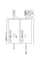
- FIG. 1 is an overall configuration diagram of a custom-made furniture design and manufacturing system according to an embodiment of the present invention.
- FIG. 2 shows an internal configuration of a custom furniture design system according to an embodiment of the present invention.
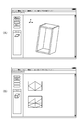
- FIG. 3A shows an example of a PC screen of the unit design system which is one embodiment of the present invention.
- FIG. 3B shows an example of a PC screen of the unit assembly system which is an embodiment of the present invention.
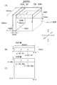
- FIG. 4A shows an example in which a rectangular parallelepiped of a part member which is an embodiment of the present invention is divided into a mouthpiece material space, a surface material space, and a core material space.
- FIG. 1 is an overall configuration diagram of a custom-made furniture design and manufacturing system according to an embodiment of the present invention.
- FIG. 2 shows an internal configuration of a custom furniture design system according to an embodiment of the present invention.
- FIG. 3A shows an example of a PC screen of the unit design system which is one embodiment of the present invention.
- FIG. 3B shows an
- FIG. 4B shows an example in which a rectangular parallelepiped of a part member which is an embodiment of the present invention is divided into a mouthpiece material space, a surface material space, and a core material space.
- FIG. 4C shows an example in which a rectangular parallelepiped of a part member which is an embodiment of the present invention is divided into a mouthpiece material space, a surface material space, and a core material space.
- FIG. 5A shows an example of part member surface association of two part members and setting of unit space in one embodiment of the present invention.
- FIG. 5B shows a view of the position of the dowel hole in the xy coordinates set on the top plate 104C surface of FIG.
- FIG. 5C is a view showing the position of the dowel hole set on the top plate 104C surface of FIG. 5B by the XY coordinates set on the left plate 102D surface.
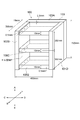
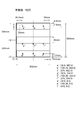
- FIG. 6 shows a bookshelf designed using the system of the present invention.
- FIG. 7A shows the cabinet 100 of the book shelf of FIG.
- FIG. 7B shows the positions of dowel holes provided on the 104C surface of the top plate 104 of the cabinet 100 of FIG.
- FIG. 7C is a diagram showing the position of the dowel hole provided by transferring the dowel hole provided on the top plate 104C surface of FIG. 7B to the 102D surface in the XY coordinates of the 102D surface.
- FIG. 8 shows an example of the part member surface association given between the part members of the cabinet of FIG. FIG.
- FIG. 10A shows an example in which dowel hole machining is given to the left side plate 102 with reference to the position of the shelf plate 106 in FIG.
- FIG. 10B shows a reference position that is virtually set using the XY coordinates of the surface of the shelf plate 106C in order to give a dowel hole to the surface of the left side plate 102D of FIG. 10C shows the position of the dowel hole provided in the 102D plane based on the reference position virtually set using the XY coordinates of the shelf board 106C shown in FIG. The figure represented by is shown.
- FIG. 10A shows an example in which dowel hole machining is given to the left side plate 102 with reference to the position of the shelf plate 106 in FIG.
- FIG. 10B shows a reference position that is virtually set using the XY coordinates of the surface of the shelf plate 106C in order to give a dowel hole to the surface of the left side plate 102D of FIG. 10C shows the position of the dowel hole provided in the 102D plane
- FIG. 11 shows a change in the position of the dowel hole associated with the change in the position of the movable shelf of the book shelf in FIG.
- FIG. 12 shows a change in the position of the dowel hole associated with the change in the dimensions of the book shelf in FIG.
- FIG. 13 shows a change in the position of the dowel hole associated with the change in the position of the movable shelf of the book shelf in FIG.
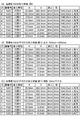
- FIG. 14 shows an example of the configuration details (BOM) data of the bookshelf of FIG. 6 designed using the system of one embodiment of the present invention.
- FIG. 15 (A) shows an example of processing details applied to the surface of the parts member of the cabinet of the book shelf of FIG. 6 designed using the system of one embodiment of the present invention.
- FIG. 15B shows the processing details when the height of the bookshelf of FIG. 6 designed using the system of one embodiment of the present invention is lowered by 10 mm.
- FIG. 15C shows the processing details when the height position of the movable shelf of the book shelf of FIG. 6 designed by using the system of one embodiment of the present invention is lowered by 10 mm.
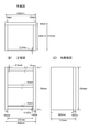
- FIG. 16A shows a plan view of the book shelf of FIG. 6 designed using the system of one embodiment of the present invention.
- FIG. 16B shows a front view of the book shelf of FIG. 6 designed using the system of one embodiment of the present invention.
- FIG. 16C shows a right side view of the book shelf of FIG. 6 designed using the system of one embodiment of the present invention.
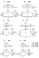
- FIG. 17A is a front view, a plan view, and a side view of the right side plate of the book shelf of FIG. 6 designed using the system of the present embodiment.
- FIG. 17B is a front view, a plan view, and a side view of the left side plate of the book shelf of FIG. 6 designed using the system of this embodiment.
- FIG. 17C is a front view, a plan view, and a side view of the (C) top plate of the book shelf of FIG. 6 designed using the system of the present embodiment.
- FIG. 17D is a front view, a plan view, and a side view of the (D) back plate of the book shelf of FIG. 6 designed using the system of the present embodiment.
- FIG. 17E is a front view, a plan view, and a side view of the (E) main plate of the book shelf of FIG. 6 designed using the system of the present embodiment.
- FIG. 17F is a front view, a plan view, and a side view of the shelf board 106 of the book shelf shown in FIG. 6 designed using the system of this embodiment.
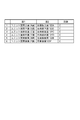
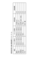
- FIG. 18 shows an example of the master data of the price and the procurement period of the members used for the furniture designed by the system of one embodiment of the present invention.
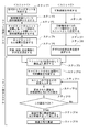
- FIG. 19 shows a flow of designing, receiving an order for, and manufacturing orders for custom-made furniture using the system of one embodiment of the present invention.
- FIG. 20A shows an example of a book shelf with drawers designed using the system of the present invention.
- FIG. 20B shows an example of a drawer inner box of a book shelf with drawer designed using the system of the present invention.
- FIG. 21 shows an embodiment of a book shelf with a door designed using the system of the present invention.
- FIG. 22 shows an example of processing applied to a furniture member designed by the system of one embodiment of the present invention.
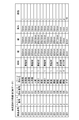
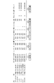
- FIG. 23 shows an example of machining data in one embodiment of the present invention.
- “furniture” widely includes housing equipment such as storage shelves, kitchen shelves, and unit baths.
- the members constituting the furniture are mainly wooden, but are not limited to specific materials, and may be made of plastic, metal, stone, marble, or glass.
- a “unit design system” refers to a tool that forms part of the system of the present invention.
- the unit design system creates part parts of furniture part members, assigns processing information to the positions specified by the XY coordinates of the six rectangles of each part member, and further adds one or more processing information Create a unit from the parts.
- a “unit assembly system” is a tool for creating furniture products by combining units created by a unit design system.
- the unit assembly system moves the position of the unit space on the screen, changes the dimensions by combining them, designs the furniture of the size and shape desired by the customer, gives the part number of the designed furniture product, and the furniture product
- the BOM data and processing details data of the member are output.
- the “part member” refers to a basic member constituting furniture such as a plate material.
- the contours of the parts are all rectangular parallelepiped shapes, and it is understood that the contours of the rectangular parallelepiped shapes are processed with holes, grooves, notches and the like to form an actual shape.
- the part member is designed as a rectangular parallelepiped space on the PC screen. The dimensions of the vertical and horizontal thicknesses of the rectangular parallelepiped of the part member are set as lengths in the X-axis, Y-axis, and Z-axis directions from the origin of the XYZ coordinates (local coordinates) set on the PC screen.
- Each dimension of the part member is set as a variable value or a fixed value.
- values in the vertical and horizontal directions are made variable, and values in the thickness direction are set to be fixed.
- the selected process is registered at a position specified by the XY coordinates of each of the six surfaces of the rectangular parallelepiped.
- the “accessory part” refers to a part used as an accessory of a furniture part member such as a dowel or a screw. Since the size of accessory parts such as dowels and screws is determined by the standard and it is not necessary to select or change according to the size of the part member, usually without setting a rectangular parallelepiped space for the accessory parts, A dowel, screw or the like of a predetermined standard is registered in the memory as a master and applied to a specified position on the surface of the part member. The accessory part applied to the surface of the part member is output in the configuration specification (BOM) together with the data of the part member.
- BOM configuration specification
- the hinge bracket, door handle, drawer rail, etc. are part bracket parts used by being attached to the furniture part member, but these are handled in the same way as the part member, and the smallest tertiary
- the original circumscribed cuboid space is set as the contour.
- Hinge brackets, door handles, drawer rails, etc. are non-cuboid shapes, but the contours of the members themselves are rectangular parallelepiped, and the actual shape can be changed by cutting, notching, drilling, etc. Set as configured.
- the hinge bracket, door handle, drawer rail, etc. need to be selected or changed according to the dimensions of the parts, so the hinge bracket, door handle, drawer rail, etc. have a rectangular parallelepiped space. And the vertical and horizontal thicknesses of the rectangular parallelepiped can be changed by changing the dimensions in the XYZ axis directions on the PC screen. If necessary, the hinge bracket, door handle, and drawer rail can be set as accessories such as dowels, screws, etc. instead of parts. Conversely, dowels, screws, etc. can be handled as parts metal fitting parts, and these circumscribed rectangular parallelepiped spaces can be set so that the dimensions can be selected or changed.
- a “unit” refers to a solid that is a structural unit of a product.
- a plurality of part members can be combined and set as a single unit, or a single part member can be set as a single unit.
- what is a part member, a unit, or a combination of a unit and a unit in a product in which a plurality of part members are combined is a design matter of the designer. The designer can set the member as necessary, such as fixing the member as a part of another solid body or allowing the member to be arranged independently.
- the cabinet 100 uses a box body composed of the respective part members of the five plate members, that is, the left and right side plates, the ground plate, the top plate, and the back plate, as one unit, and the shelf plate 106 has one part member. It is set as another unit consisting of one part member. It is also possible to set the shelf board 106 as one of the part members constituting the cabinet 100 as well as other side boards, top boards, ground boards, back boards and the like.
- the shelf board 106 When the shelf board 106 is accommodated in the cabinet 100 so as to be able to be put in and out using a dowel, it is advantageous in design and desirable to set the shelf board 106 as a single unit composed of one part member.
- the cabinet, the door, and the handle of the door can be set as a unit, respectively.
- the door and the handle can be set as part members, and the combination of both can be set as a door with a handle. It is also possible to set as
- a “skeleton unit” refers to a unit having a space that can accommodate all or part of another unit (infill unit) therein.
- an “infill unit” refers to a unit that is entirely or partially accommodated in a space (cell space) inside another unit (skeleton unit).
- a cabinet constituted by a combination of parts is a skeleton unit, and a drawer constituted by a combination of parts is equivalent to an infill unit.
- the other dimension is not changed in conjunction with the dimension change for one, but by associating the planes with each other through the cell space (described later), The other can be interlocked with the dimension change with respect to one.
- the “circumscribed cuboid space” refers to a virtual three-dimensional cuboid space circumscribing a solid.
- the solid is a rectangular parallelepiped plate and the dimensions are 300 mm in length, 500 mm in width, and 20 mm in thickness
- the space of the size of the outline of the plate becomes the circumscribed cuboid space of the solid as it is.
- a non-cubic solid such as a hinge fitting
- the smallest rectangular parallelepiped space that can accommodate the fitting is the circumscribed rectangular parallelepiped space of the solid.
- the space indicated by the broken line is a solid circumscribed rectangular parallelepiped space composed of two part members, the side plate and the top plate.
- unit space refers to a virtual three-dimensional cuboid space circumscribing one unit.
- the space for circumscribing the unit is referred to as the “unit space” of the unit.
- the position of the part member belonging to the unit can be easily calculated and / or set in the relative positional relationship with the unit space.
- a three-dimensional cuboid space circumscribing the unit is usually set as a unit space.
- a rectangular parallelepiped space obtained by reducing or expanding a three-dimensional rectangular parallelepiped space circumscribing the unit can be set as a unit space as necessary.
- the size of the part member is changed by changing the size of the unit space of the unit formed by the part member.
- the dimensions of the unit space are changed, the dimensions of one or more part members associated with the six surfaces of the unit space and the unit space / part member surface can be changed.
- the dimensions of the one unit space are changed, thereby changing the dimensions of the one other unit space.
- the dimensions can be changed. Thereby, the dimension of the unit which comprises each unit space, and the dimension of the part member which comprises a unit can be changed interlockingly.
- the position of each part constituting the unit is set based on the unit space according to the distance between each of the six parts of the unit space and the corresponding part member. can do.
- the dimension / position of the part member can be changed in conjunction with each other by changing the size / position of the unit space.
- the “cell space” refers to a space in which all or part of the infill unit can be inscribed inside the skeleton unit.
- the unit space of the infill unit can be accommodated in the cell space.
- the position of the infill unit inscribed in the cell space can be set with reference to the cell space according to the distance between each of the six surfaces of the unit space of the infill unit corresponding to each of the six surfaces of the cell space. .
- the shelf board 106 is set as one unit composed of one part member by itself, so that the cabinet 100 (a combination of a plurality of part members) and the shelf board 106 are separated from each other. Is a unit. If the part members 101, 102, 103, 104, 105 and the shelf board 106 constituting the cabinet 100 are not associated with each other in terms of the part member surfaces, the other member is changed in conjunction with one another when the dimensions are changed. There is no. However, when the shelf is stored in the cabinet, if a change to reduce the size of the cabinet is input, the shelf cannot be accommodated in the cabinet unless the size of the shelf is changed in conjunction with the change.
- the cabinet and the shelf board both follow the change of the shared space by changing the shared space. Can be changed.
- the cabinet and the shelf board can be resized in conjunction with each other. become. *
- the “composite board” refers to, for example, a surface material such as a polyplywood attached to the surface of the core material, and a mouthpiece material such as a tape to the cross section of the mouthpiece, as shown in FIG. In some cases, it refers to a plate material composed of these members.
- the “composite plate” is a part member and has a rectangular parallelepiped outline.
- the “surface material space” refers to a rectangular parallelepiped space formed by dividing a rectangular parallelepiped of a composite plate (part member) into dimensions of a surface material attached to a core material.
- “Kiuchi material space” refers to a rectangular parallelepiped space formed by dividing a part member of a composite plate into the dimensions of a lip material to be affixed to a core material.
- the “core material space” refers to a rectangular parallelepiped space that remains as a core material portion when the surface material space and the mouthpiece material space are divided from the part member of the composite plate.
- the part member of the composite plate will be described using the unit design system.
- the initial value depth dimension of the composite plate as the part member is 300 mm
- the initial thickness dimension is 15 mm
- the thickness of the end piece and the surface material is set to 1 mm, respectively.
- the composite plate is changed so that the end material is not attached to the back end face. As a simple method for the change, it is possible to change the thickness of the lumber space on the back end face to zero.
- the depth dimension of the composite board space as the part member is set to 300 mm
- the depth dimension (298 mm) of the core material and the surface material is increased by the thickness dimension (1 mm) of the deleted mouthpiece material. It is changed to be 299 mm.
- the composite plate as the part member of FIG. 4 (A) is changed so as not to attach the surface material to the upper surface.
- the thickness of the upper surface material it is possible to change the thickness of the upper surface material to zero.
- the thickness dimension of the core material 13.0 mm
- the thickness dimension of the deleted upper surface material To 14.0 mm.
- product refers to a furniture product produced by combining a plurality of units on the screen of the system of the present invention.
- a product number is assigned to a product designed by the system of the present invention. The same product number is allotted to the unit constituting the product, the part member constituting the unit, the surface material constituting the part member, the mouthpiece material, and the core material.
- the “product space” refers to a virtual three-dimensional cuboid space circumscribing a product composed of one or a plurality of unit spaces.
- the position of the unit space of each unit constituting the product can be set based on the product space according to the distance between each of the six surfaces of the product space and the corresponding unit space surface.
- unit space / part member surface association means a distance between one surface of a part member constituting a unit and one surface corresponding to the parallel of the unit space of the unit. This means that the faces are related by specifying.
- Part member surface association means specifying a distance between one surface of a part member and one surface of another part member corresponding to the surface in parallel. This refers to associating faces. If the distance between two surfaces associated with a part member surface is zero, both surfaces are coplanar with each other.
- part member surface association means specifying a distance between one surface of a part member and one surface of another part member corresponding to the surface in parallel. This refers to associating faces. If the distance between two surfaces associated with a part member surface is zero, both surfaces are coplanar with each other.
- the cooperative relationship between the unit space / part member surface association and the part member surface association will be described with reference to FIG.
- a plate material 104 thickness 20 mm, vertical length 300 mm, horizontal length 500 mm
- the plate material 102 has a height of 500 mm and a depth of 300 mm
- the plate material 104 has a vertical length of 300 mm and a horizontal length of 500 mm.
- the plate material 102 has a thickness of 30 mm and the plate material 104 has a thickness of 20 mm, which are set as fixed values.
- the part member surface association is given between the part member of the plate member 102 and the part member of the plate member 104.
- the inter-plane distances between the 102A plane and the 104A plane, the 102B plane and the 104B plane, and the 102F plane and the 104F plane that are parallel to each other are designated as zero.
- the distance between the 102D surface and the 104C surface is designated as 0.5 mm.
- a solid composed of the part member 102 and the part member 104 is set as a unit A.
- a circumscribed cuboid space (shown by a broken line) circumscribing both the part member 102 and the part member 104 is set as a unit space, and six surfaces (A, B, C, D, E, F) of the unit space of the unit A are set. And a part-part surface association is given as follows between the part member 102 and the part member 102 constituting the unit A.
- the upper surface (A surface) of the unit space is parallel to the 102A surface and the distance between the surfaces is zero.
- the front surface (B surface) of the unit space is parallel to the 102B surface and the distance between the surfaces is zero.
- the left side surface (C surface) of the unit space is parallel to the 102C surface and the inter-surface distance is zero.
- the right side surface (D surface) of the unit space is parallel to the 104D surface and the inter-surface distance is zero.
- the lower surface (E surface) of the unit space is parallel to the 102E surface and the inter-surface distance is zero.
- the rear surface (F surface) of the unit space is parallel to the 102F surface and the inter-surface distance is zero.
- the 104 D surface associated with the unit space surface (D surface) and the unit space / part member surface is linked to the right direction. Moving. Since the horizontal length 500 mm of the plate material 104 is variably set, the horizontal length 500 mm of the plate material 104 (part member) is increased by 10 mm to 510 mm.
- the left surface (C surface) of the unit space When the left surface (C surface) of the unit space is moved 10 mm in the left direction (C direction of the arrow), the left surface (C surface) of the unit space and the 102 C surface associated with the unit space / part member surface are linked to the left direction. Moving. Since the thickness of the plate member 102 is fixed at 30 mm, when the 102C surface moves 10 mm to the left, the 102D surface opposite to 102C also moves 10 mm to the left. Since the 102D surface and the 104C surface are connected to each other with a distance of 0.5 mm between the surface parts, if the 102D surface moves 10 mm to the left, the 104C surface also follows and moves 10 mm to the left.
- the horizontal length of the plate material 104 (part member) is variably set, when the 104C surface moves 10 mm to the left, the horizontal length of the plate material 104 (part member) is increased by 10 mm to 510 mm. Since the 104D plane is not associated with the C plane, the 102C plane, or the 102D plane in the unit space, the position does not change. *
- the surface 102A associated with the surface A of the unit space and the unit space / part member surface is upward 10 mm (direction A of arrow).
- the 102A surface and the 104A surface are related to each other by a part member surface with a surface distance of zero, if the 102A surface moves 10 mm upward (direction A of the arrow), the 104A surface also moves 10 mm upward (indicated by the arrow Move in direction A). Since the thickness of the plate member 104 is fixed to 30 mm, when the 104A surface moves upward, the 104E surface, which is the opposite surface of the 104A surface, also moves 10 mm upward (direction A of the arrow).
- unit space surface association means that one surface of six unit spaces of one unit and one other surface when one product is composed of a plurality of units. This means that the positional relationship between the two units is set by designating the inter-surface distance between one unit plane in parallel with the unit space.
- cell space / unit space plane association means between the plane of the cell space of the skeleton unit and the corresponding parallel plane of the unit space of the infill unit accommodated in the cell space. This means that the surfaces are related by specifying the distance.
- the inter-surface distance between the surface of the unit space of the infill unit and the surface of the cell space corresponding to the plane is specified.
- the cell space / unit space surface association and the unit space surface association are basically the same, and only the space of the other party of the surface association is a unit space or a cell space.
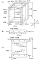
- machining refers to machining applied to a part member such as drilling, grooving, or notching.
- all the part members have a rectangular parallelepiped outline, and it is understood that the rectangular parallelepiped is machined to form an actual shape.
- a specific process is selected from the process master data registered in the memory, and the selected process is registered at the designated position of the XY coordinates of the rectangular parallelepiped surface of the part member.
- the “machining position” refers to the position on the surface of the rectangular parallelepiped of the part member to which the machining selected using the system of the present invention is input.
- the processing position is indicated by using the rectangular XY coordinates of the surface to be processed.
- the center positions of holes A, B, C, and F are machining positions, and the size of the holes is specified by the diameter from the center position.
- For the groove E four points a, b, c and d surrounding the horizontally long rectangle of the groove are designated as processing positions.
- the notch D four points p, q, r, and s surrounding the rectangle in front of the notched corner of the plate to be processed are designated as processing positions.
- Pieces of processing position information are minimum information necessary for the processing machine to determine a position where processing such as a hole, a groove, and a notch is performed on a processing target.
- the processing machine can receive the position information and other necessary information (hole, groove depth, etc.) and machine the part member.
- a “processing machine” refers to a device used by a furniture manufacturer to machine components of furniture, such as a dowel hammer, a tenoner, or a cut-and-sew machine.
- the BOM data and the processing specification data output from the system of the present invention are encoded so as to be readable by the processing machine in the manufacturing plant.
- the BOM data and the machining specification data output from the system of the present invention include information about a processing target (a plate material or the like), information about a processing content to be applied to the processing target, and information about a position to which processing is applied.
- the manufacturing plant that has received the data output from the system of the present invention, based on the received configuration specification and processing specification data, the type and processing method of the processing machine used for processing according to the processing capability of the processing machine provided by itself Is selected and processing is applied to the plate material.
- the plate member has a certain thickness, width, and length, and a hole A having a diameter of 8 mm is formed on the front surface using three length NCs (drills).
- B and C are cup holes for attaching metal fittings, and the cup holes are often formed using a dedicated cup hole processing machine, but can also be formed by a drill with a normal NC machine.
- D is a notch provided in the upper right corner of the plate material, and can be formed using a corner cutter.
- E is a groove formed with a width of 3 mm and a depth of 6 mm in the longitudinal and transverse direction of the plate material, and can be formed using a tenoner.
- F is a through hole having a diameter of 50 mm and can be formed using a drill of an NC machine.
- the processing machines of the processing plant that processes the plate material may be the same or different.
- both the A factory and the B factory can be performed by the same processing machine (NC machine drill, corner cutter).
- Factory A is equipped with a tenoner, so it can be formed with it, but factory B is not equipped with a tenor, so it is formed using an NC machine drill.
- the BOM data and the machining specification data output from the system of the present invention include information about a processing target (plate material or the like), information on the type / content of processing to be applied to the processing target, and information on a position to which processing is applied. Preferably, it is provided in a standardized form so that it can be read by the other side.
- FIG. 23 shows an example of the format of BOM data and processing specification data provided from the system of the present invention to a processing machine.
- the manufacturing factory can process and manufacture furniture members based on the BOM data and the processing specification data by receiving data in a standardized format from the system of the present invention and reading the data with a processing machine that the manufacturing factory has.
- Coordinat transformation is a method in which a position specified by an XY coordinate of one surface of one rectangular parallelepiped is specified by an XY coordinate of a surface parallel to the one surface of another rectangular parallelepiped. To convert to a certain position.
- the left side surface 104C of the top plate 104 is joined and fixed to the inner side surface 102D of the left side plate 102 using a dowel.
- the mutual positional relationship between the top plate 104 and the six sides of a virtual rectangular parallelepiped space (unit space indicated by a broken line) circumscribing the top plate 104 and the left side plate 102, and the top plate It is defined by the inter-surface distance between each surface 104 and each surface of the left side plate 102.
- the relationship between the left side plate 102 and the unit space is that the 102A surface is parallel to the upper surface of the unit space and the inter-surface distance is zero, and the 102B surface is parallel to the front surface of the unit space and the inter-surface distance. Is zero, the 102C surface is parallel to the left surface of the unit space and the inter-surface distance is zero, the 102D surface is the opposite surface of the 102C surface, and the thickness of 102 is fixed to 30 mm.
- the 102E plane is parallel to the lower surface of the unit space and has a zero inter-plane distance, and the 102F plane is parallel to the rear surface of the unit space and has a zero inter-plane distance.
- the relationship between the top plate 104 and the unit space is that the 104A surface is parallel to the upper surface of the unit space and the inter-surface distance is zero, and the 104B surface is parallel to the front surface of the unit space and the inter-surface distance. Is zero, and the 104C surface is 102 mm away from the left surface of the unit space plus 0.5 mm, the 104D surface is parallel to the right surface of the unit space and the inter-surface distance is zero, and the 104E surface is 104A
- the opposite surface 104 has a fixed thickness of 30 mm, and the 104F surface is parallel to the rear surface of the unit space and has an inter-plane distance of zero.
- the positions of the dowel holes a and b to be registered on the left side surface 104C of the top plate 104 are designated by XY coordinates with the lower left front corner of the rectangle of the 104C surface as the origin.
- the XY coordinate position of a is (100 mm, 10 mm)
- the coordinate position of b is (200 mm, 10 mm).
- the left side plate 101 corresponding to the center positions a (100 mm, 10 mm) and b (200 mm, 10 mm) of the two dowel holes registered on the left side surface 104C of the top plate 104
- the position on the XY coordinate on the 102D surface of the left side plate 102 of a'b' is the shelf plate 106 and the left side plate 102. From the positional relationship, a ′ (100 mm, 490 mm), b ′ (200 mm, 490 mm) can be obtained.
- the system of the embodiment of the present invention can be operated as application software that operates on an OS such as Windows (registered trademark).
- An application programming interface such as OpenGL (registered trademark) is preferably installed as a three-dimensional computer graphic interface between the OS and the application software of this system.
- FIG. 1 shows an overall configuration diagram of a furniture design system according to one embodiment of the present invention.
- the furniture design system is connected to a manufacturing factory 6 and a PC provided in the sales agent 4 or the house maker 5. Furthermore, the furniture design system has a website 3.
- the sales agent 4 or the house maker 5 proposes a product designed using the furniture design system 1 of the present invention to the customer 2 based on the PC or the catalog.
- distributor 4 or house maker 5 Upon receiving a request for a change in dimensions or specifications from customer 2, distributor 4 or house maker 5 re-suggests the goods designed by changing the dimensions or specifications using furniture design system 1 along with their estimated price and delivery date. To do.
- a purchase order is received from a customer in the specification size and price storage period of the reproposed product, the data is transmitted to the furniture design system 1.
- the furniture design system 1 that has received the order calculates data necessary for manufacturing the ordered product based on the input data, and transmits the data generated by the calculation to the manufacturing factory 6 that performs manufacturing cooperation.
- the customer can directly order without going through the sales agent or the house maker by accessing the website 3 set up by the custom-made furniture design system 1 and entering the goods of the desired size. Is also possible.
- FIG. 2 shows an internal configuration of a furniture design system that is an embodiment of the present invention.
- This system 1 designs a furniture product by assembling a unit design system for designing a furniture unit, a unit designed by the unit design system, and further, based on the data of part parts having the same product part number, It consists of a unit assembly system that outputs the component specifications (BOM) of the members that make up the product and the processing details of each member.
- BOM component specifications
- the designer creates a unit by accessing the unit design system and inputting dimensional information, combination information, and processing information for the part member of the furniture.
- a person who wants to order furniture designed by the system of the present invention accesses the unit assembly system, calls a unit previously created by the unit design system and registered in the memory, and adjusts the dimensions of the unit.
- a product is designed by combining units, and a component specification (BOM) and a processing specification of the designed product are output to a manufacturing factory.
- BOM component specification
- the component configuration details and processing details of the part members of the designed product are classified and created for each unit and product, and sent to the manufacturing factory 6 together with the product number.
- a design drawing is sent.
- This system 1 sends the manufacturing data to the manufacturing factory 6 without printing out the six-sided drawings of the products designed and ordered according to the customer's wishes, and the manufacturer draws the design drawings in his / her own style. It is also possible to print out.
- FIG. 3A shows an example of a PC screen of the unit design system which is an embodiment of the present invention.
- FIG. 3B shows an example of a PC screen of the unit assembly system which is an embodiment of the present invention.
- all the ridge lines of the members are set to be aligned in any direction of the XYZ coordinate axes in the PC screen.
- all members are grasped as a rectangular parallelepiped, and therefore, the three sides extending from one corner of the rectangular parallelepiped are set to extend in any direction of the world coordinate XYZ axes in the PC screen.
- FIG. 6 shows a bookshelf designed using the system of the embodiment of the present invention.
- the book shelf in FIG. 6 includes a cabinet 100 (unit 1) and a shelf board 106 (unit 2).
- the cabinet 100 of the unit 1 is composed of five part members: a right side plate 101, a left side plate 102, a back plate 103, a top plate 104, and a ground plate 105.
- the unit 2 is a unit composed of only one part member of the shelf board 106.
- A. 1. Operation by unit design system Create a unit in the unit design system.
- ⁇ Cabinet creation> Step 1) Assemble plate materials to create a cabinet.
- the plate material data is read by clicking the plate material icon, the plate material (part member) of the temporary size is displayed on the screen according to the size of the temporary vertical and horizontal thicknesses of the plate material stored in the memory.
- the displayed plate material (part member) is copied to create the required number of part members (5 in this embodiment).
- an initial dimension of the plate material (part member), a variable / fixed distinction, and a maximum / minimum value setting (optional) when the dimension is variable are input.
- the cabinet 100 includes five part members (a right side plate 101, a left side plate 102, a back plate 103, a top plate 104, and a base plate 105).
- the initial dimensions of the right side plate 101 and the left side plate 102 are 700 mm (variable) in height, 300 mm (variable) in depth, and 15 mm (fixed) in thickness.
- the initial dimensions of the top plate 104 and the base plate 105 are both horizontal 370 mm (variable), depth 299.5 mm (variable), and thickness 15 mm (fixed).
- the initial dimensions of the back plate 103 are a lateral length of 400 mm (variable), a height of 700 mm (variable), and a thickness of 15 mm (fixed).
- Step 2) Associate the part member surfaces between the plate members.
- the CPU automatically assigns identification codes to the six surfaces of each part member.
- the upper surface is the A surface
- the front surface is the B surface
- the left surface is the C surface
- the right surface is the D surface
- the lower surface is the E surface
- the rear surface is the F surface
- the left side plate 102 has six surfaces 102A, 102B, 102C, 102D, 102E, 102F
- the back plate 103 has six surfaces 103A, 103B, 103C, 103D, 103E, 103F
- the top plate 104 is the top plate 104.
- Identification codes of 104A, 104B, 104C, 104D, 104E, and 104F are assigned to the six faces, and 105A, 105B, 105C, 105D, 105E, and 105F are assigned to the six faces of the ground plane 105.
- surface association is started with the left side plate 102 as a reference as follows. 1.
- the right side surface 102D of the left side plate 102 and the left side surface 104C of the top plate 104 are parallel to each other and on the same plane. 2.
- the right side surface 102D of the left side plate 102 and the left side surface 105C of the base plate 105 are parallel to each other and on the same plane. 3.
- the left side surface 102C of the left side plate 102 and the left side surface 103C of the back plate 103 are parallel to each other and on the same plane. 4).
- the front surface 102B of the left side plate 102 and the front surface 101B of the right side plate 101 are parallel to each other and on the same plane. 5.
- the front surface 102B of the left side plate 102 and the front surface 104B of the top plate 104 are parallel to each other, and 102B is separated from 104B by 0.5 mm. 6).
- the front surface 102B of the left side plate 102 and the front surface 105B of the base plate 105 are parallel to each other, and 102B is separated from 105B by 0.5 mm. 7).
- the rear surface 102F of the left side plate 102 and the rear surface 101F of the right side plate 101 are parallel to each other and on the same plane. 8).
- the rear surface 102F of the left side plate 102 and the rear surface 104F of the top plate 104 are parallel to each other and on the same plane. 9.
- the rear surface 102F of the left side plate 102 and the rear surface 105F of the ground plate 105 are parallel to each other and on the same plane. 10.
- the rear surface 102F of the left plate 102 and the front surface 103B of the back plate 103 are parallel to each other and on the same plane.
- the upper surface 102A of the left side plate 102 and the upper surface 104A of the top plate 104 are parallel to each other, and 102A is separated from 104A by 0.5 mm.
- the upper surface 102A of the left side plate 102 and the upper surface 101A of the right side plate 101 are parallel to each other and on the same plane.
- the lower surface 102E of the left side plate 102 and the lower surface 105E of the base plate 105 are parallel to each other, and 102E is separated from 105E by 0.5 mm.
- the lower surface 102E of the left side plate 102 and the lower surface 101E of the right side plate 101 are parallel to each other and on the same plane.
- the upper surface 102A of the left side plate 102 and the upper surface 103A of the back plate 103 are parallel to each other and on the same plane.
- the lower surface 102E of the left side plate 102 and the lower surface 103E of the back plate 103 are parallel to each other and on the same plane.
- the cabinet 100 cannot be completely defined only by the surface association based on the left side plate. Therefore, after completing the surface association started with the left side plate as a reference, the right side plate 101 and the back plate 103, the top plate 104, and the ground plate 105 are associated with each other as follows. 17.
- the left side surface 101C of the right side plate 101 and the right side surface 104D of the top plate 104 are parallel to each other and on the same plane. 18.
- the left side surface 101C of the right side plate 101 and the right side surface 105D of the ground plane 105 are parallel to each other and on the same plane. 19.
- the right side surface 101D of the right side plate 101 and the right side surface 103D of the back plate 103 are parallel to each other and on the same plane.
- FIG. 8 shows the part member surface association given between the respective parts constituting the cabinet 100 as described above.
- the cabinet 100 that is made up of part members associated with each other in terms of part member surfaces is referred to as a unit 1.
- the unit design system calculates the circumscribed cuboid space of the unit 1 as the unit space.
- Step 3) The unit space between the six unit spaces (A surface, B surface, C surface, D surface, E surface, F surface) of the unit 1 created above and each part member constituting the unit 1 A part member surface association is given.
- the upper surface (A surface) of the unit space is parallel to the upper surface 102A of the left side plate 102 and the inter-surface distance is zero.
- the lower surface (E surface) of the unit space is parallel to the lower surface 102E of the left side plate 102, and the distance between the surfaces is zero.
- the left side surface (C surface) of the unit space is parallel to the left side surface 102C of the left side plate 102, and the inter-surface distance is zero. 4).
- the right side surface (D surface) of the unit space is parallel to the right side surface 101D of the right side plate 101 and the inter-surface distance is zero. 5.
- the front surface (surface B) of the unit space is parallel to the front surface 102B of the left side plate 102, and the distance between the surfaces is zero. 6).
- the rear surface (F surface) of the unit space is parallel to the rear surface 103F of the back plate 103, and the inter-surface distance is zero.
- FIG. 9 shows the unit space / part member surface association provided between the unit space of the unit 1 (cabinet 100) and each part member constituting the unit 1 as described above.
- the surface of the part member constituting the unit 1 is associated with the surface corresponding to the unit space of the unit 1 in parallel with that of the unit space.
- the surface of each part member is directly or indirectly associated with the surface corresponding to the parallel of other part members.
- neither the right side plate 101E surface nor the left side plate 102E surface is associated with the part member surface with respect to the top plate 104E surface.
- the right side plate 101A surface and the left side plate 102A surface are not associated with the part member surface with respect to the main plate 105A. Since the thickness of the top plate 104 is fixed, and the heights of the right side plate 101, the left side plate 102, and the back plate 103 are set to be variable, the right side plate 101E surface, the left side plate 102E surface, and the right side plate 101A are set.
- Each of the surface and the left side plate 102A can move up and down, and by moving these surfaces up and down, the height of the cabinet 100 can be changed while the thickness of the top plate 104 is fixed. it can.
- Step 4) After the above-described plane association for setting the cell space in the cabinet is completed, the cell space P is set in the internal space of the cabinet 100.
- the cell space P has an A plane, a B plane, a C plane, a D plane, an E plane, and an F plane according to the six-direction arrows shown in the lower right of FIG.
- the A surface, C surface, D surface, E surface, and F surface of the cell space P face the 104E surface, 102D surface, 101C surface, 105A surface, and 103B surface of the cabinet 100, respectively. Since the front surface of the cabinet 100 is an opening, there is no part member surface facing the B surface of the cell space P.
- Step 5 Dowel holes are provided in the top plate, base plate, and left and right side plates.
- three outer diameters of 6 mm and a depth of 8 mm are provided on the left and right ends of the top plate 104 and the base plate 105 respectively.
- a cylindrical dowel hole is provided.
- the dowel holes are provided in the inner surfaces of the left and right side plates by transferring the dowel holes provided in the top surface of the top plate and the base plate to the corresponding positions of the left and right side plates.
- the position of the dowel hole is specified by the XY coordinates of the surface of the part member in the system of the embodiment of the present invention, the position is set based on the position of the center of the circular circle of the dowel hole.
- FIG. 7B shows the left cuff surface 104C surface of the top plate 104 of the cabinet 100 of FIG.
- FIG. 7C shows the positions of three dowel holes in the XY coordinates on the 102D surface when the 104C surface is joined to the left side plate 102D surface.
- the top surface of the top plate 104 is provided with a Chile level difference with respect to the top surfaces of the side plates 101 and 102, and is retracted 0.5 mm.
- the lower surface of the ground plate 105 is provided with a Chile level difference with respect to the lower surfaces of the side plates 101 and 102 and is raised by 0.5 mm.
- the 104B surface of the top plate and the 105B surface of the ground plate are both recessed by 0.5 mm with respect to the front surface 101B surfaces and 102B surfaces of the left and right plates 101 and 102.
- two-dimensional coordinates are set in which the lower left corner of the 104C plane rectangle is the origin (0, 0), and two sides extending from the origin are the x-axis and the y-axis.
- Three dowel holes a, b, and c are provided in the rectangular lateral direction, a and c at positions 30 mm from both ends, and b at the center position that bisects the length of the horizontal side.
- a, b, and c are all at the center position that bisects the length of the vertical side (15 mm).
- the depth of the top plate is 299.5 mm which is 0.5 mm shorter than the depth length of 300 mm of the side plate, and the thickness (fixed) of the top plate is 15 mm.
- the positions of the three dowel holes a, b, c are a (30 mm, 7.5 mm), b (149.75 mm, 7.5 mm), c (269.5 mm, 7.5 mm), respectively. It becomes.
- dowel holes a, b, and c on the 104C surface are projected in a direction perpendicular to the left side plate 102 (D) surface of the cabinet 100 to be a'b'c '. .
- the positions of a′b′c ′ are a ′ (30.5 mm, 692.0 mm), b ′ (150.25 mm, 692.0 mm) and c ′ (270.0 mm, 692.0 mm).
- the cabinet 100 has a bilaterally symmetric structure, the same applies to the top plate 104D surface and the right side plate 101C surface, and the ground plate 105D surface and the right side plate 101C surface.
- Step 6 The movable shelf board 106 (unit 2) is created.
- the plate material read by clicking the icon is displayed on the screen as a part member of the movable shelf 106.
- the initial dimensions of the movable shelf board are set to a lateral length of 369 mm, a depth length of 299.5 mm, and a thickness of 15 mm (fixed).
- the lateral length of the movable shelf is set to be 1 mm smaller than the lateral width of the cell space of the cabinet so that the movable shelf can be easily moved in the cabinet.
- Step 7) The movable shelf 106 is set as the unit 2, and the unit space / part member surface is associated with the unit space of the unit 2 with a distance between the surfaces of zero.
- the movable shelf 106 is set as the unit 2 including only one part member.
- the circumscribed cuboid space of the unit 2 is set as the unit space of the unit 2 as it is.
- Step 8) Position the dowel hole of the dowel that supports the shelf board.
- three dowel holes for supporting the bottom of the movable shelf board with dowels are provided on the right side surface 102D of the left side plate 102.
- FIG. In order to make the movable shelf plate 106 movable up and down in the cabinet, it is necessary to set so that the position of the dowel hole provided on the surface of the left side plate 102D changes according to the height position of the shelf plate 106.
- the position of the dowel hole provided in the surface of the side plate 102D is set with reference to the position of the cuff surface 106C surface of the movable shelf 106, and the virtual reference position set with reference to the cuff surface 106C of the shelf plate 106 is used.
- a position on the side plate 102D surface specified by projecting in a direction perpendicular to the 102D surface is defined as a dowel hole position on the 102D surface.
- xy coordinates (local coordinates) having the origin at the lower left corner of the rectangular shape of shelf 106C surface are set, and reference positions g, h, i is specified by an XY coordinate set to a rectangle on the surface of the shelf board 106C.
- the initial dimensions of the movable shelf 106 are a depth length of 299.5 mm, a thickness of 15 mm, and the outer diameter of the dowel hole is 6 mm. Therefore, the dowel hole reference positions g, h, i are the shelf boards.
- the cabinet 100 since the shelf plate 106 is set to be provided at a height position that bisects the length in the height direction of the left and right side plates, the cabinet 100 is vertically symmetrical with the shelf plate 106 in between. . Therefore, the setting of the dowel hole between the top plate and the side plate can be copied between the main plate and the side plate. Moreover, since the cabinet 100 which accommodates the shelf board 106 is bilaterally symmetrical, the dowel hole (reference position) set in the surface of the shelf board 106 and the dowel hole processing from there to the surface of a side board are the surface of a shelf board. The information set in can be copied to the opposite side.
- Step 9) Display units 1 and 2 on the screen.
- a unit of a desired type is read from the units designed in the unit design system and registered in the memory, and displayed on the screen.
- the unit of the cabinet is read and displayed as unit 1
- the unit composed of the part members of the plate material for the shelf board is read and displayed as unit 2.
- Step 10) The movable shelf board (unit 2) is accommodated in the cabinet (unit 1). In the cell space P of the cabinet 100 shown in FIG. 6, the movable shelf board 106 is dragged and moved to a desired height position. In FIG. 6, the movable shelf board 106 is initially installed at the center position in the height direction of the left and right side boards.
- the shelf board 106 is accommodated in the cell space P surrounded by the side plates 101 and 102, the top board 104, the ground board 105, and the back board 103 which are part members of the cabinet 100.
- the four surrounding surfaces (106B surface, 106C surface, 106D surface, 106F surface) of the shelf plate 106 correspond to the four surfaces (B
- the cell space / unit space surface is associated with a surface distance of zero with respect to the surface, C surface, D surface, and F surface).
- dowel holes for supporting the shelf on the inner surfaces of the left and right side plates are transferred to the side plates.
- the shelf board 106 is supported on the lower surface by dowels inserted into the three dowel holes provided on the left side plate, so that the dowel holes are not provided on the top surface of the shelf board itself.
- An imaginary reference position for determining the position of a dowel hole provided on the surface of the left side plate 102D facing the shelf's front end face 106C is set.
- the reference positions g, h, i of the dowel holes on the shelf 106C surface are g (30 mm, ⁇ ) in the xy coordinates (local coordinates) whose origin is the lower left corner of the rectangle on the 106C surface. 0.3 mm), h (149.75 mm, -0.3 mm), i (269.5 mm, -0.3 mm).
- g ′′, h ′′ and i ′′ are positions specified by projecting onto the right side surface 102D of the left side plate 102 in a direction perpendicular to the 106C plane from the respective positions g, h and i, g ′′ and h ′′.
- I ′′ are coordinates ⁇ g (30.5 mm, 339.5 mm), h ′′ (150.25 mm, 339.5 mm), i ′′ (270 mm, 339.5 mm).
- the dowel processing input to the positions g, h, i specified with respect to the cuff surface of the shelf plate 106 becomes g ′′ of the right side surface 102D of the left side plate 102. Transfer is automatically input at the positions h ′′ and i ′′.
- Step 11 Inputting unit change of dimensions
- the operation of changing the depth of the cabinet 100 (unit 1) from 300 mm to 400 mm will be described with reference to FIG. 6, FIG. 7, FIG.
- the thickness of the back plate 103 is fixed, and with reference to FIG. Since both surfaces are associated with the part member surface with a distance between the surfaces of the back plate 103B of zero, the 102F surface of the left plate 102 and the 101F surface of the right plate 101 both move in the 100 mm depth direction (F direction). . Since the depth lengths of the left side plate 102 and the right side plate 101 are set to be variable, the depth lengths of the left side plate 102 and the right side plate 101 extend 100 mm to 400 mm.
- the back plate 103F surface and 103B are moved by moving the rear surface (F surface) of the unit space in the F direction. Even if the surface moves in the F direction, it does not move in conjunction.
- FIG. 11 shows the positions of the dowel holes after the depth of the cabinet 100 is changed from 300 mm to 400 mm.
- FIG. 9 since the upper surface (A surface) of the unit 1 is associated with the left-side plate upper surface 102A and the unit / part surface, if the height of the unit 1 is 690 mm, The distance between them is moved 10 mm downward in conjunction with it according to zero). Then, referring to FIG. 8, the upper surface 104A of the top plate 104 is associated with the upper surface 104A of the top plate 104 in parallel with each other at a setting of 0.5 mm away from the upper surface 104A of the top plate 104.
- the left side plate upper surface 102A is associated with the upper surface 101A of the right side plate 101 and the upper surface 103A of the back plate 103 at a distance of zero, so that when the left side plate upper surface 102A is moved downward by 10 mm, it interlocks with it.
- the right side plate 101A surface and the back plate 103A surface are also moved downward by 10 mm.
- the height dimension of the part members 101, 102, and 103 is reduced by 10 mm in accordance with the input of changing the height of the unit 1 to 690 mm, so that all become 690 mm.
- FIG. 12 shows the positions of the dowel holes after the height of the cabinet 100 is changed from 700 mm to 690 mm.
- FIG. 12 shows the setting of the position of the dowel hole on the surface of the left side plate 102D, but the setting of the position of the dowel set on the surface of the right side plate 101C is the same.
- the lower surface 106E of the shelf plate 106 is 342 from both the lower surface 102E of the left side plate 102 and the lower surface 101E of the right side plate 101. It is installed at a distance of 5 mm (700 mm ⁇ 1 / 2-7.5 mm).
- the part member of the shelf board 106 is the unit 2, and its surrounding four surfaces (B surface, C surface, D surface, F surface) are the distances between the surfaces of the B space, C surface, D surface, and F surface of the cell space P.
- the cell space / unit space surface is associated with zero, but the upper surface (A surface) and the lower surface (E surface) are not designated the distance between the surfaces, so the shelf 106 is set for the four surrounding surfaces It can move freely in the vertical direction while following the cell space / unit space plane association.
- the shelf plate 106 When the shelf plate 106 is moved downward 10 mm so that the distance from the bottom surface 101 of the bottom surface 106E becomes 332.5 mm, as shown in FIGS. 10C and 13, the reference positions g, h on the 106C surface , I is lowered by 10 mm, and as a result, the Y coordinate is lowered by 10 mm on the XY coordinates set on the 102D surface of machining g ′′, h ′′, and i ′′ applied to the 102D surface.
- FIG. 13 shows the position of the dowel hole after the height position of the shelf board of the cabinet 100 is changed to be 10 mm lower.
- Step 12 The specifications, estimated price, and delivery date of the designed bookshelf are calculated and displayed.
- the price of the bookshelf designed through the dimension change in step 11) and the estimated delivery date are calculated based on the members constituting the bookshelf and the procurement period, and the result is displayed on the PC screen together with the three-dimensional image of the designed bookshelf. Display above.
- FIG. 18 is an example of the master data of the price and the procurement period of the members used for the bookshelf of this embodiment.
- the prices and lead times for individual parts are provided by the manufacturing plant 6 and stored in the memory of the system of the present invention.
- the estimated price of the product is the total of the price of the parts and materials used for manufacturing the product, based on the price of each member registered in the master data of the parts and materials.
- the delivery date of the product is based on the time required for procurement of each member registered in the master data of the parts material, and the delivery time of the bookshelf is the one with the longest procurement period among the multiple parts materials used for manufacturing the product. Calculate by adding the processing, assembly production period, packing, and carry-in period.
- Step 13) The customer is inquired as to whether the output displayed product is OK.
- a book shelf with dimensions changed by a change input to the unit is output and displayed on the PC screen as a stereoscopic image. If the customer is satisfied with the specifications, estimated price, and delivery date of the product output on the screen, the customer decides to purchase the proposed furniture. If the displayed specification, price, or delivery date is not satisfied and a correction is desired, the process returns to the change input in step 11).
- an adhesive or a screw is used as a joining means between the part members. They can be set and given as processing for the part member. Alternatively, the method of joining the part members can be left to a manufacturing factory that cooperates with the manufacturing without specifying it in the system of the present invention.
- Step 14) The manufacturing data of the product ordered from the customer is sent to the manufacturing factory through the furniture design system 1.
- manufacturing data provided to a manufacturing factory 1.
- FIG. 14 shows the component configuration data (BOM data) of a book shelf designed using the system of the present embodiment.
- a product number 001 is assigned to the bookshelf.
- Unit numbers 1 and 2 are assigned to the two units (cabinet and shelf) constituting the book shelf, respectively.
- Each part member of the units 1 and 2 is assigned a part member number, and a material, a width, a height, a thickness, and a number are designated for each part member.
- FIG. 15A shows processing details of dowel holes to be given to the left side plate 102 of the book shelf designed using the system of this embodiment.
- FIG. 15B shows the details of processing the dowel hole of the left side plate 102 when the height of the book shelf is lowered by 10 mm.
- FIG. 15C shows the details of machining the dowel hole of the left side plate 102 when the position of the shelf plate 106 is lowered by 10 mm.
- FIGS. 15A, 15B, and 15C show only dowel hole machining provided to the left side plate 102D facing the shelf plate 106C, but also between the right side plate 101C facing the shelf plate 106D. Similar dowel hole machining is provided.
- FIGS. 16A, 16B, and 16C are a plan view, a front view, and a right side view of the book shelf of FIG. 6 designed by using the system of this embodiment, respectively.
- FIGS. 17A to 17F show (A) right side plate, (B) left side plate, (C) top plate, and (D) back of the book shelf of FIG. 6 designed using the system of this embodiment. It is a front view, a top view, and a side view of a board, (E) ground plane, and (F) shelf board 106. (F) Since the shelf board 106 uses the composite board, the application of the surface material and the lip material to be affixed to its six surfaces is shown.
- Step 15) The manufacturing factory receives the data of the configuration details (BOM) and the processing details, and manufactures the product according to the data.
- the manufacturing factory can automatically process the ordered furniture on the automatic manufacturing line by receiving the configuration details (BOM data) in FIG. 14 and the processing details data in FIG. 15 in cooperation with this system. Is possible.
- the manufacturing plant uses the design drawings shown in FIGS. 16 (A)-(C) and 17 (A)-(F) to manufacture furniture ordered by a method based on conventional drawings, without using an automatic manufacturing line. You can also Alternatively, the manufacturing plant can also manufacture the ordered furniture by using an automatic manufacturing line and a conventional manufacturing method in combination.
- Example 2 (storage case with drawer) 20A and 20B show a storage case with a drawer which is another embodiment of the present invention.
- the drawer storage case shown in FIG. 20 includes a cabinet 100 (unit 1), a drawer inner box 200 (unit 2), a drawer front plate 300 (unit 3), and a handle 400 (unit 4).
- the handle 400 has a non-cuboid shape, the minimum circumscribed rectangular parallelepiped space is defined as the contour of the handle 400, and is handled as a part member having a rectangular parallelepiped contour like the plate material.
- Unit 1 (cabinet 100) is a skeleton unit and has a cell space P1 and a cell space P2.
- the unit 2 (drawer inner box) is an infill unit.
- the unit 2 is accommodated in the cell space P2 of the cabinet 100 and associated with the cell space / unit space surface.
- the unit 3 (the drawer front plate 300) and the unit 4 (the handle 400) are combined with the unit 2 (the drawer inner box) to form a drawer, and the drawer is combined with the cabinet (unit 1) to provide a product with a drawer.
- a storage case is constructed.
- the unit 1 (cabinet 100) includes parts members such as a right side plate 101, a left side plate 102, a back plate 103, a top plate 104, a base plate 105, and a shelf plate 106, which are parts members.
- Each part member of the unit 1 is associated with the six surfaces of the unit space of the unit 1 and the unit space / part member surface, and the parallel surfaces of each part member are associated with each other.
- the part members of the unit 2 are composed of a drawer left end plate 201, a drawer right end plate 202, a drawer bottom plate 203, and a drawer destination plate 204.
- Each part member of the unit 2 is associated with the six surfaces of the unit space of the unit 2 and the unit space / part member surface, and the parts member surfaces are associated with each other in parallel with each other.
- the part member of the unit 3 pre-drawer plate 300
- the handle 4 is the only part member of the unit 4 (the handle 400).
- the respective unit spaces are associated with each other in the unit space plane.
- the front surface (surface B) of the unit space of the drawer inner box is designated as zero.
- the unit spaces are associated with each other in the unit space plane, and in the unit space plane association, the rear surface of the unit space of the unit 3 (front drawer) ( The inter-surface distance between the front surface (B surface) of the unit space of the unit 1 (cabinet 100) is designated as 5 mm.
- the unit spaces are associated with each other in the unit space plane, and in the unit space plane association, the front surface of the unit space on the front plate (B surface). And the rear face (F face) of the drawer handle is designated as zero.
- the lower surface of the unit space of the unit 1 is associated with the unit space / part member surface.
- the lower surface of the member moves 10 mm downward (E direction).
- the lower surface of the other part member associated with that part member and the part member surface is moved downward by 10 mm according to the inter-surface distance set in the part member surface association, and the dimension of the other part member is changed accordingly.
- the dimensions of the cell space P2 of the unit 1 (cabinet 100) are changed.
- the dimension of the unit space of the drawer inner box unit 2 associated with the cell space P2 and the cell space / unit space surface is changed.
- the dimension of each part member constituting the drawer inner box unit 2 is changed according to the unit space / part member surface association and the part member surface association.
- the dimensions of the drawer front plate unit are changed in accordance with the unit space plane association provided between the unit space of the unit 1 and the unit space of the front plate unit 3. As a result, the dimension of the part member of the pre-drawer plate is changed.
- the dimensions of the drawer front plate unit 3 are changed, the dimensions of the handle unit 4 attached to the drawer front plate are changed to the front surface (B surface) of the unit space of the front plate unit 3 and the unit space F of the handle unit 4. It is changed according to the unit space plane association set with the inter-plane distance to the plane set to zero. As a result, the dimension of the part member of the drawer handle is changed.
- FIG. 21 shows a storage case with a door which is another embodiment of the present invention.
- 21 includes a cabinet 100 (unit 1), a door 300 (unit 2), and a handle 400 (unit 3).
- An interval of 2 mm is provided between the door 200 and the cabinet 100.
- the part member surfaces are associated with each other between the surfaces of the part members constituting the unit 1 (cabinet 100) with a distance between the surfaces of zero. Between the unit space of the unit 1 and the surface of each part member constituting the unit 1 (cabinet 100), the unit space / part member surface is associated with a distance between the surfaces of zero.
- the unit space 1 of the unit 1 and the unit space 2 of the unit 2 (door) are associated with each other by providing a space of 2 mm between the door and the cabinet.
- the upper surface (A surface) of the unit space 1 and the upper surface (A surface) of the unit space 2 are parallel to each other and on the same plane.
- the left side surface (C surface) of the unit space 1 and the left side surface (C surface) of the unit space 2 are parallel to each other and on the same plane.
- the right side surface (D surface) of the unit space 1 and the right side surface (D surface) of the unit space 2 are parallel to each other and on the same plane.
- the lower surface (E surface) of the unit space 1 and the lower surface (E surface) of the unit space 2 are parallel to each other and on the same plane.
- the front surface (B surface) of the unit space 1 of the unit 1 and the rear surface (F surface) of the unit space 2 of the unit 2 are parallel to each other and the distance between the surfaces is 2 mm.
- the door thickness is fixed at 15 mm.
- the unit 2 (door) and the unit 3 (door handle 400) are joined to the front surface of the door (the circumscribed cuboid space).
- the upper surface (A surface) of the unit space 2 and the upper surface (A surface) of the unit space 3 are parallel to each other and separated from each other by a predetermined distance.
- the left side surface (C surface) of the unit space 2 and the left side surface (C surface) of the unit space 3 are parallel to each other and separated from each other by a predetermined distance.
- the right side surface (D surface) of the unit space 2 and the right side surface (D surface) of the unit space 3 are parallel to each other and separated from each other by a predetermined distance.
- the lower surface (E surface) of the unit space 2 and the lower surface (E surface) of the unit space 3 are parallel to each other and separated from each other by a predetermined distance.
- the front surface (B surface) of the unit space 1 of the unit 1 and the rear surface (F surface) of the unit space 2 of the unit 2 (door) are parallel to each other and on the same plane.
- the present invention can be applied to furniture having a more complicated structure. Further, the present invention can be suitably used for the design and manufacture of furniture, but its application is not limited to furniture, and it can be used for the design and manufacture of three-dimensional structures composed of a plurality of constituent members. it can.
Landscapes
- Engineering & Computer Science (AREA)
- Physics & Mathematics (AREA)
- Theoretical Computer Science (AREA)
- General Engineering & Computer Science (AREA)
- General Physics & Mathematics (AREA)
- Computer Hardware Design (AREA)
- Geometry (AREA)
- Architecture (AREA)
- Evolutionary Computation (AREA)
- Software Systems (AREA)
- Civil Engineering (AREA)
- Human Computer Interaction (AREA)
- Computer Graphics (AREA)
- Structural Engineering (AREA)
- Computational Mathematics (AREA)
- Mathematical Analysis (AREA)
- Mathematical Optimization (AREA)
- Pure & Applied Mathematics (AREA)
- Combinations Of Kitchen Furniture (AREA)
Priority Applications (6)
| Application Number | Priority Date | Filing Date | Title |
|---|---|---|---|
| JP2017533043A JP6276898B2 (ja) | 2016-02-02 | 2017-01-31 | コンピュータを用いたオーダーメード家具の設計及び製造方法、システム、及びそのためのプログラム |
| US15/572,061 US10713395B2 (en) | 2016-02-02 | 2017-01-31 | Method for designing and manufacturing custom-made furniture using computer, system, and program therefor |
| KR1020177032311A KR20180108416A (ko) | 2016-02-02 | 2017-01-31 | 컴퓨터를 사용한 오더 메이드 가구의 설계, 제조 방법, 시스템 및 그것을 위한 프로그램 |
| CN201780001527.8A CN107615281B (zh) | 2016-02-02 | 2017-01-31 | 使用计算机设计家具的部件的方法及系统 |
| EP17747378.2A EP3321830B1 (en) | 2016-02-02 | 2017-01-31 | Method for designing and manufacturing custom-made furniture using computer, system, and program therefor |
| US16/926,633 US11829685B2 (en) | 2016-02-02 | 2020-07-10 | Method for designing and manufacturing custom-made furniture using computer, system, and program therefor |
Applications Claiming Priority (2)
| Application Number | Priority Date | Filing Date | Title |
|---|---|---|---|
| JP2016-018216 | 2016-02-02 | ||
| JP2016018216 | 2016-02-02 |
Related Child Applications (2)
| Application Number | Title | Priority Date | Filing Date |
|---|---|---|---|
| US15/572,061 A-371-Of-International US10713395B2 (en) | 2016-02-02 | 2017-01-31 | Method for designing and manufacturing custom-made furniture using computer, system, and program therefor |
| US16/926,633 Continuation US11829685B2 (en) | 2016-02-02 | 2020-07-10 | Method for designing and manufacturing custom-made furniture using computer, system, and program therefor |
Publications (1)
| Publication Number | Publication Date |
|---|---|
| WO2017135222A1 true WO2017135222A1 (ja) | 2017-08-10 |
Family
ID=59501020
Family Applications (1)
| Application Number | Title | Priority Date | Filing Date |
|---|---|---|---|
| PCT/JP2017/003324 Ceased WO2017135222A1 (ja) | 2016-02-02 | 2017-01-31 | コンピュータを用いたオーダーメード家具の設計及び製造方法、システム、及びそのためのプログラム |
Country Status (6)
| Country | Link |
|---|---|
| US (2) | US10713395B2 (enExample) |
| EP (1) | EP3321830B1 (enExample) |
| JP (3) | JP6276898B2 (enExample) |
| KR (1) | KR20180108416A (enExample) |
| CN (1) | CN107615281B (enExample) |
| WO (1) | WO2017135222A1 (enExample) |
Families Citing this family (18)
| Publication number | Priority date | Publication date | Assignee | Title |
|---|---|---|---|---|
| WO2019022221A1 (ja) * | 2017-07-28 | 2019-01-31 | ドゥーマンズ株式会社 | コンピュータを用いて設計した家具のパーツ部材を加工機械を用いて製造するためのシステム、方法、及びそのためのプログラム |
| US11507711B2 (en) | 2018-05-18 | 2022-11-22 | Dollypup Productions, Llc. | Customizable virtual 3-dimensional kitchen components |
| US11373015B2 (en) * | 2018-07-16 | 2022-06-28 | Dassault Systemes Solidworks Corporation | Designing a 3D modeled object representing a mechanical structure |
| CN109308131A (zh) * | 2018-08-24 | 2019-02-05 | 无锡加简软件开发有限公司 | 一种开槽机输入方法 |
| JP2020173559A (ja) * | 2019-04-09 | 2020-10-22 | Vuild株式会社 | 加工処理システム、加工処理プログラム、及び加工処理方法 |
| WO2020263736A1 (en) * | 2019-06-26 | 2020-12-30 | Dollypup Productions, LLC | Customizable virtual 3-dimensional kitchen components |
| CN110390150B (zh) * | 2019-07-11 | 2023-05-12 | 广州市云家居云科技有限公司 | 一种基于多个单元的方案组合全局参数控制方法 |
| CN111127653B (zh) * | 2019-11-22 | 2023-06-16 | 久瓴(江苏)数字智能科技有限公司 | 正置式平屋面生成方法、装置、计算机设备和存储介质 |
| USD959477S1 (en) | 2019-12-20 | 2022-08-02 | Sap Se | Display system or portion thereof with a virtual three-dimensional animated graphical user interface |
| US11205296B2 (en) * | 2019-12-20 | 2021-12-21 | Sap Se | 3D data exploration using interactive cuboids |
| USD959447S1 (en) | 2019-12-20 | 2022-08-02 | Sap Se | Display system or portion thereof with a virtual three-dimensional animated graphical user interface |
| USD959476S1 (en) | 2019-12-20 | 2022-08-02 | Sap Se | Display system or portion thereof with a virtual three-dimensional animated graphical user interface |
| CN111985014B (zh) * | 2020-08-11 | 2024-04-16 | 广联达科技股份有限公司 | 一种基于标准图集的建模方法及系统 |
| CN112307576B (zh) * | 2020-09-30 | 2022-04-08 | 成都飞机工业(集团)有限责任公司 | 一种三维立体化铣样板快速设计方法 |
| US12061570B2 (en) | 2021-02-08 | 2024-08-13 | Dollypup Productions, LLC | Three-dimensional model configurator method |
| JP7557880B2 (ja) * | 2021-04-12 | 2024-09-30 | Vuild株式会社 | 加工データ処理プログラム及び加工処理システム |
| BE1029294B1 (nl) * | 2021-04-30 | 2023-02-03 | Aluzon | Productie van structuren opgebouwd uit bouwkundige elementen |
| CN113378262B (zh) * | 2021-05-24 | 2023-04-07 | 中建钢构武汉有限公司 | 弯扭构件的加工信息获取方法、设备及存储介质 |
Citations (4)
| Publication number | Priority date | Publication date | Assignee | Title |
|---|---|---|---|---|
| JPH10162048A (ja) * | 1996-11-27 | 1998-06-19 | Toshiba Corp | 三次元cad装置 |
| WO2006064971A1 (ja) * | 2004-12-17 | 2006-06-22 | Kenichi Ninomiya | 物品の設計支援システムおよびその制御方法 |
| JP2007164576A (ja) * | 2005-12-15 | 2007-06-28 | Kenichi Ninomiya | サイズ変更可能な物品の設計データ構造 |
| US20130201189A1 (en) * | 2007-08-22 | 2013-08-08 | Trimble Navigation Limited | Systems for parametric modeling of three dimensional objects |
Family Cites Families (9)
| Publication number | Priority date | Publication date | Assignee | Title |
|---|---|---|---|---|
| DE2914436C2 (de) * | 1979-04-10 | 1981-10-01 | Pusch, Günter, Dr.-Ing., 6903 Neckargemünd | Wärmereflektierende Tapete oder Wandbelag |
| US5293479A (en) * | 1991-07-08 | 1994-03-08 | Quintero Smith Incorporated | Design tool and method for preparing parametric assemblies |
| AU6318100A (en) * | 1999-08-03 | 2001-02-19 | Kenichi Ninomiya | Design support system, design support method, and medium storing design support program |
| WO2009111885A1 (en) * | 2008-03-11 | 2009-09-17 | Dirtt Environmental Solutions, Ltd. | Automatically creating and modifying furniture layouts in design software |
| US20080172207A1 (en) * | 2007-01-11 | 2008-07-17 | Andrew Philippe Palioca | Semi-automated generation of frame structures in cad models |
| JP4977497B2 (ja) * | 2007-03-08 | 2012-07-18 | 富士通株式会社 | 部品の三次元モデルの選別を行うためのプログラム、方法、システム |
| US20110213480A1 (en) * | 2010-03-01 | 2011-09-01 | Genexis Design Inc. | Parametric product configuration system |
| JP6022290B2 (ja) * | 2012-10-03 | 2016-11-09 | ドゥーマンズ株式会社 | ユニットのデータ構造,ユニット設計装置および方法,家具設計装置,家具設計システム,ならびに家具製造支援装置 |
| WO2016157284A1 (ja) * | 2015-03-27 | 2016-10-06 | ドゥーマンズ株式会社 | オーダーメード家具の設計・受注・製造発注システム、方法、及びそのためのプログラム |
-
2017
- 2017-01-31 CN CN201780001527.8A patent/CN107615281B/zh active Active
- 2017-01-31 JP JP2017533043A patent/JP6276898B2/ja active Active
- 2017-01-31 EP EP17747378.2A patent/EP3321830B1/en active Active
- 2017-01-31 US US15/572,061 patent/US10713395B2/en active Active
- 2017-01-31 WO PCT/JP2017/003324 patent/WO2017135222A1/ja not_active Ceased
- 2017-01-31 KR KR1020177032311A patent/KR20180108416A/ko not_active Ceased
-
2018
- 2018-01-12 JP JP2018003454A patent/JP6405477B2/ja active Active
- 2018-09-12 JP JP2018170621A patent/JP6783835B2/ja active Active
-
2020
- 2020-07-10 US US16/926,633 patent/US11829685B2/en active Active
Patent Citations (4)
| Publication number | Priority date | Publication date | Assignee | Title |
|---|---|---|---|---|
| JPH10162048A (ja) * | 1996-11-27 | 1998-06-19 | Toshiba Corp | 三次元cad装置 |
| WO2006064971A1 (ja) * | 2004-12-17 | 2006-06-22 | Kenichi Ninomiya | 物品の設計支援システムおよびその制御方法 |
| JP2007164576A (ja) * | 2005-12-15 | 2007-06-28 | Kenichi Ninomiya | サイズ変更可能な物品の設計データ構造 |
| US20130201189A1 (en) * | 2007-08-22 | 2013-08-08 | Trimble Navigation Limited | Systems for parametric modeling of three dimensional objects |
Also Published As
| Publication number | Publication date |
|---|---|
| US11829685B2 (en) | 2023-11-28 |
| US20180089336A1 (en) | 2018-03-29 |
| US10713395B2 (en) | 2020-07-14 |
| JPWO2017135222A1 (ja) | 2018-02-08 |
| EP3321830A4 (en) | 2018-09-19 |
| JP6405477B2 (ja) | 2018-10-17 |
| KR20180108416A (ko) | 2018-10-04 |
| JP6783835B2 (ja) | 2020-11-11 |
| JP2018081718A (ja) | 2018-05-24 |
| EP3321830B1 (en) | 2021-09-29 |
| EP3321830A1 (en) | 2018-05-16 |
| CN107615281B (zh) | 2022-02-08 |
| US20200356705A1 (en) | 2020-11-12 |
| CN107615281A (zh) | 2018-01-19 |
| JP2019003686A (ja) | 2019-01-10 |
| JP6276898B2 (ja) | 2018-02-07 |
Similar Documents
| Publication | Publication Date | Title |
|---|---|---|
| JP6405477B2 (ja) | コンピュータを用いたオーダーメード家具の設計及び製造方法、システム、及びそのためのプログラム | |
| JP5850594B1 (ja) | オーダーメード家具の設計・受注・製造発注システム、方法、及びそのためのプログラム | |
| JP7205946B2 (ja) | 建築木工製品の自動製造 | |
| CN1326080C (zh) | 物品设计辅助系统、物品加工图作成系统以及物品使用说明书作成系统 | |
| JPWO2001009778A1 (ja) | 物品の設計支援システムおよび方法ならびに物品の設計支援のためのプログラムを格納した媒体 | |
| JP5913721B1 (ja) | 3次元立体構造物を設計し、その3次元立体構造物の寸法を変更するためのシステム及び方法 | |
| CN100538709C (zh) | 物品的辅助设计系统及其控制方法 | |
| JP6000486B1 (ja) | 複数のパーツ部材を組み合わせて構成される家具をコンピューターを用いて設計する方法及びシステム | |
| US20200004222A1 (en) | Method of simulating the rigging of a space | |
| JP6582278B2 (ja) | コンピュータを用いて設計した家具のパーツ部材を加工機械を用いて製造するためのシステム、方法、及びそのためのプログラム | |
| JP5913720B1 (ja) | 立体構造物を設計し、その寸法を変更するためのシステム及び方法 |
Legal Events
| Date | Code | Title | Description |
|---|---|---|---|
| ENP | Entry into the national phase |
Ref document number: 2017533043 Country of ref document: JP Kind code of ref document: A |
|
| 121 | Ep: the epo has been informed by wipo that ep was designated in this application |
Ref document number: 17747378 Country of ref document: EP Kind code of ref document: A1 |
|
| WWE | Wipo information: entry into national phase |
Ref document number: 15572061 Country of ref document: US |
|
| ENP | Entry into the national phase |
Ref document number: 20177032311 Country of ref document: KR Kind code of ref document: A |
|
| NENP | Non-entry into the national phase |
Ref country code: DE |