WO2017134898A1 - Dispositif de fixation de gabarit de maintien - Google Patents
Dispositif de fixation de gabarit de maintien Download PDFInfo
- Publication number
- WO2017134898A1 WO2017134898A1 PCT/JP2016/084047 JP2016084047W WO2017134898A1 WO 2017134898 A1 WO2017134898 A1 WO 2017134898A1 JP 2016084047 W JP2016084047 W JP 2016084047W WO 2017134898 A1 WO2017134898 A1 WO 2017134898A1
- Authority
- WO
- WIPO (PCT)
- Prior art keywords
- holding jig
- fixing
- jig
- fixing device
- holding
- Prior art date
Links
Images


Classifications
-
- B—PERFORMING OPERATIONS; TRANSPORTING
- B64—AIRCRAFT; AVIATION; COSMONAUTICS
- B64F—GROUND OR AIRCRAFT-CARRIER-DECK INSTALLATIONS SPECIALLY ADAPTED FOR USE IN CONNECTION WITH AIRCRAFT; DESIGNING, MANUFACTURING, ASSEMBLING, CLEANING, MAINTAINING OR REPAIRING AIRCRAFT, NOT OTHERWISE PROVIDED FOR; HANDLING, TRANSPORTING, TESTING OR INSPECTING AIRCRAFT COMPONENTS, NOT OTHERWISE PROVIDED FOR
- B64F5/00—Designing, manufacturing, assembling, cleaning, maintaining or repairing aircraft, not otherwise provided for; Handling, transporting, testing or inspecting aircraft components, not otherwise provided for
- B64F5/10—Manufacturing or assembling aircraft, e.g. jigs therefor
-
- B—PERFORMING OPERATIONS; TRANSPORTING
- B21—MECHANICAL METAL-WORKING WITHOUT ESSENTIALLY REMOVING MATERIAL; PUNCHING METAL
- B21J—FORGING; HAMMERING; PRESSING METAL; RIVETING; FORGE FURNACES
- B21J15/00—Riveting
- B21J15/10—Riveting machines
- B21J15/28—Control devices specially adapted to riveting machines not restricted to one of the preceding subgroups
-
- B—PERFORMING OPERATIONS; TRANSPORTING
- B21—MECHANICAL METAL-WORKING WITHOUT ESSENTIALLY REMOVING MATERIAL; PUNCHING METAL
- B21J—FORGING; HAMMERING; PRESSING METAL; RIVETING; FORGE FURNACES
- B21J15/00—Riveting
- B21J15/10—Riveting machines
- B21J15/14—Riveting machines specially adapted for riveting specific articles, e.g. brake lining machines
- B21J15/142—Aerospace structures
-
- B—PERFORMING OPERATIONS; TRANSPORTING
- B64—AIRCRAFT; AVIATION; COSMONAUTICS
- B64C—AEROPLANES; HELICOPTERS
- B64C1/00—Fuselages; Constructional features common to fuselages, wings, stabilising surfaces or the like
- B64C1/06—Frames; Stringers; Longerons ; Fuselage sections
- B64C1/12—Construction or attachment of skin panels
-
- B—PERFORMING OPERATIONS; TRANSPORTING
- B23—MACHINE TOOLS; METAL-WORKING NOT OTHERWISE PROVIDED FOR
- B23P—METAL-WORKING NOT OTHERWISE PROVIDED FOR; COMBINED OPERATIONS; UNIVERSAL MACHINE TOOLS
- B23P2700/00—Indexing scheme relating to the articles being treated, e.g. manufactured, repaired, assembled, connected or other operations covered in the subgroups
- B23P2700/01—Aircraft parts
Definitions
- the present invention relates to a holding jig fixing device.
- the fuselage panel of the aircraft is configured by combining a plate-like skin having a curved surface, an elongated stringer provided on the skin along the longitudinal direction of the fuselage, and a frame provided along the circumferential direction of the fuselage, etc. Ru.
- Bonding of overlapping portions of adjacent skins and bonding of a frame to a skin or stringer are performed after the position of each part is accurately determined using a positioning jig.
- a rivet is used for the connection between parts.
- a positioning jig is used by being fixed at a predetermined position in a factory, and the above-mentioned coupling of the skins and the coupling of the frame are performed at the predetermined position to manufacture the body panel.
- the fuselage panel being manufactured was moved from the work place of one process to the work place of the next process, it was removed from the positioning jig and moved, and the positioning jig itself did not move.
- the positioning jig fixed and used at the predetermined position is manufactured in advance according to the shape of the body panel to be manufactured.
- the fuselage panel is not only in the case of a single curved surface having a straight line in the longitudinal direction, but also in the case of a double curved surface having a curvature in the longitudinal direction. Therefore, many types of positioning jigs need to be manufactured in accordance with the shape of the body panel, and the cost for manufacturing and managing the jigs is also increased.
- the torso panel fixed to the jig moves the plurality of work spaces while moving the fuselage panel.
- the panel is a finished product.
- the positional accuracy and the shape accuracy of the jig are determined in each working space.
- the present invention has been made in view of such circumstances, and can secure the positional accuracy and the shape accuracy of the moving holding jig, and can fix the holding panel with high accuracy. It aims at providing an apparatus.
- a holding jig fixing device is a plurality of fixings that are provided on an installation surface and support and fix a holding jig that holds an aircraft panel having a curved cross section from the lower surface of the holding jig.
- a plurality of fixing portions are provided corresponding to at least four corners of the lower surface of the holding jig.
- the holding jig holds the aircraft panel having a curved cross section, and the plurality of fixing portions support and fix the holding jig from the lower surface.
- the plurality of fixing portions are provided on the installation surface, and the holding jig is positioned by being supported and fixed by the plurality of fixing portions.
- the plurality of fixing portions are provided corresponding to at least four corners of the lower surface of the holding jig, so that the holding jig can be prevented from spreading in four directions, and the shape accuracy of the holding jig can be secured.
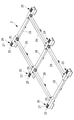
- the holding jig is a curved shape corresponding to two parallel linear members facing each other and a curved shape of the aircraft panel, and a plane perpendicular to the axial direction of the linear members. It has two curvilinear members provided inside and facing each other, and both ends of the linear member are respectively connected with the ends of the different curvilinear members.
- the holding jig has two linear members and two curvilinear members, and the linear members are respectively connected at the ends of different curvilinear members, so that they are substantially wedge-shaped. It has the shape of Therefore, in the lower part of a curvilinear member, it is easy to spread outward and rigidity is low. As described above, since the plurality of fixing portions are provided corresponding to at least four corners of the lower surface of the holding jig, the holding jig can be prevented from spreading in four directions, and the shape accuracy of the holding jig can be secured. .
- the fixing portion or the lower surface of the holding jig corresponding to the fixing portion is provided with a positioning portion that defines the position of the holding jig in the horizontal direction or the height direction.
- a laser beam is irradiated to a stage portion to which the positioning portion is fixed and a reflector placed on the stage portion, and the laser beam reflected by the reflector is received to detect the position of the reflector And a controller configured to adjust the position of the stage based on the position of the reflector detected by the laser tracker.
- the plurality of fixing portions are connected to each other via a girder member.
- position accuracy and shape accuracy of a moving holding jig can be secured, and an aircraft panel can be assembled with high accuracy.
- the holding jig fixing device 2 is applied to a body panel manufacturing system in which the holding jig 1 is transported on a line.
- a transport track is provided, the holding jig 1 moves in one direction along the transport track, and in each work space, the holding jig 1 is fixed to the trunk panel 10 Rivet setting work etc. are performed. That is, while the work is performed, the body panel 10 is fixed, and the body panel 10 moves only when being transported between the work spaces.
- the moving method and the process procedure of the holding jig 1 do not need to be changed according to the type of the body panel 10, so that all types of body panels 10 can be manufactured on the same production line.
- the holding jig 1 has a predetermined shape of the aircraft panel when, for example, the skins constituting the aircraft panel are overlapped and joined by rivets, or when the frame is joined to the skin or stringer by rivets. Used to hold
- the fuselage panel 10 of the aircraft includes a plate-like skin 11 having a curved surface, an elongated stringer 12 provided on the skin 11 along the longitudinal direction of the fuselage (longitudinal direction), and the fuselage A frame (not shown) provided along the circumferential direction is combined and configured.
- the fuselage panel 10 is made of, for example, aluminum or aluminum alloy, and an example of the size is 10 m in longitudinal length, 6 m in chord length, and 2 mm to 5 mm in thickness.
- the fuselage panel 10 has a substantially cylindrical fuselage portion of the aircraft divided in the axial direction and the circumferential direction. Therefore, the fuselage panel 10 has an arc shape in cross section in the direction perpendicular to the machine axis direction. In the fuselage panel 10, two opposing sides parallel or oblique to the machine axis direction are straight lines, and are positioned at the lower end of the fuselage panel 10 when the fuselage panel 10 is held by the holding jig 1.
- the two opposing sides that fit in a plane perpendicular to the machine axis direction are arc-shaped, and are located at the side ends of the fuselage panel 10 when the fuselage panel 10 is held by the holding jig 1 .
- the holding jig 1 has a transportable configuration, and for example, as shown in FIG. 3, the holding jig 1 is placed on the transport device 15 and transported from one end side to the other end side.
- the conveying device 15 is provided with a conveyor 16 such as a chain conveyor or a belt conveyor (see FIGS. 5 and 6), and the conveyor 16 is rotated by driving a motor (not shown). It is wound parallel to the horizontal member 6 and provided.
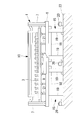
- the holding jig 1 is made of, for example, aluminum or an aluminum alloy. In FIG. 1, the holding jig 1 is shown being fixed to the holding jig fixing device 2.
- the plurality of grips 3 are supported by the support member 5, fixed in relative position and integrated, and have a shape in which bottom portions of two horizontal members 6 are accommodated in the same plane.
- the holding jig 1 can be transported by the transport device 15.
- the rivet setting operation is not performed on the body panel 10, and the rivet setting is performed on the trunk panel 10 in a state where the holding jig 1 is fixed at one place.
- Work is done. For example, when the automatic tapping machine is placed at a predetermined place and the rivet setting by the automatic tapping machine is completed, the holding jig 1 is conveyed by the conveyance device 15 to another place. At the transported location, other automatic tapping machines are placed, and riveting by the other automatic tapping machines is performed. Alternatively, at the transported place, a working place by a worker is used, and riveting or inspection by hand is performed.
- the holding jig 1 which concerns on this embodiment is provided with the frame material 4, the supporting material 5, and the holding part 3 grade
- the body panel 10 is held by the holding jig 1, the body panel 10 is held so as to be convex upward.
- the frame member 4 is composed of two straight horizontal members 6 extending in one direction, and two arch members 7 disposed between the two horizontal members 6 and formed in an arch shape.
- the horizontal members 6 and the arch members 7 of the frame member 4 support a support member 5 described later.
- the horizontal members 6 are disposed, for example, parallel to the axial direction of the fuselage panel 10 along the axial direction of the fuselage panel 10 installed in the holding jig 1.
- the lower end of the arch member 7 is coupled to one end and the other end of the horizontal member 6.
- the holding jig 1 has a substantially wedge shape by the two horizontal members 6 and the two arch members 7.
- the girder member which couples one end or the other end of the two horizontal members 6 and extends in the vertical direction with respect to the horizontal member 6 is not provided.
- the length of the horizontal members 6 is longer than the axial length of the fuselage panel 10 manufactured by riveting, and the arrangement distance between the two horizontal members 6 is greater than the chordal length of the fuselage panel 10 manufactured by riveting Too long.
- the arch member 7 is a frame member 4 having a curved shape, and is disposed in a plane perpendicular to the axial direction of the fuselage panel 10 installed in the holding jig 1.
- the arch members 7 are provided one each on one end side and the other end side of the horizontal member 6 and are coupled to the two horizontal members 6.
- the frame member 4 has a configuration in which the horizontal member 6 and the arch member 7 are integrated.
- the curved shape, for example, the curvature, of the arch member 7 is provided substantially corresponding to the curvature of the body panel 10 to be manufactured.
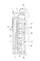
- the support member 5 is disposed between two straight lower end support members 8 extending in the machine axis direction and the two lower end support members 8 and has two arched side end support members 9 and the like. It consists of
- the lower end support 8 supports the lower end of the fuselage panel 10 via the grip 3.
- the lower end support member 8 is located above the horizontal member 6 of the frame member 4 and is parallel to, for example, the axial direction of the fuselage panel 10 along the axial direction of the fuselage panel 10 installed in the holding jig 1. Or it is arranged to be in an oblique direction.
- the lower end support members 8 are arranged corresponding to the two opposing sides of the body panel 10 installed in the holding jig 1. For example, the lower end support 8 is disposed along the ends of the straight two opposing sides of the fuselage panel 10.
- the body panel 10 to be manufactured is a single curved surface having the same curvature all along the machine axis direction
- the extending direction of the lower end support 8 and the horizontal member 6 is parallel.
- the body panel 10 to be manufactured is a double curved surface whose curvature changes along the machine axis direction
- the extending direction of the lower end support member 8 is oblique to the extending direction of the horizontal member 6.
- the lower end support member 8 is supported by the horizontal member 6 via, for example, an auxiliary member 21 provided between the lower end support member 8 and the horizontal member 6.
- the auxiliary member 21 is a member having one end connected to the horizontal member 6 and the other end connected to the lower end support 8.
- a plurality of auxiliary members 21 are arranged along the longitudinal direction of the horizontal member 6 and the lower end support 8. .
- a plurality of grips 3 are arranged on the lower end support 8 at intervals.
- the length of the lower end support 8 is longer than the length in the machine axial direction of the body panel 10 to be manufactured, and the arrangement distance between the two lower end supports 8 is longer than the chord length of the body panel 10 to be manufactured.
- the lower end support member 8 is positioned lower than the held body panel 10 so that the grip portion 3 supports the lower end portion of the body panel 10 from the lower side.
- the lower end of the side end support 9 is coupled to one end and the other end of the lower end support 8 in the longitudinal direction.
- the side end support 9 supports the side end of the fuselage panel 10 via the grip 3.
- the side end support 9 is a member having a curved shape, and is disposed in a plane perpendicular to the axial direction of the fuselage panel 10 installed in the holding jig 1.
- the side end support members 9 are disposed corresponding to the two opposing sides of the body panel 10 installed in the holding jig 1.
- the side end supports 9 are provided respectively on one end side and the other end side of the lower end support 8 in the longitudinal direction, and are connected to the two lower end supports 8.
- the support 5 has a configuration in which the lower end support 8 and the side end support 9 are integrated.
- the curved shape, for example, the curvature, of the side end support 9 is provided corresponding to the curvature of the body panel 10 to be manufactured.
- a plurality of gripping portions 3 having the same configuration as the gripping portions 3 described above may be provided on the side end support members 9, and the gripping portions 3 may grip and support the side edge of the body panel 10.
- the plurality of gripping portions 3 provided on the side end support members 9 are provided at intervals corresponding to the curvature of the body panel 10 to be manufactured. Therefore, when the plurality of grips 3 grip the body panel 10, the body panel 10 gripped by the grips 3 is held so as to have the curvature of the body panel 10 to be manufactured.
- the body panel 10 to be manufactured is a single curved surface having the same curvature all along the machine direction, the curvature connecting the grips 3 in the side end support 9 on one end side and the side end support on the other side
- the curvature connecting the grips 3 in the material 9 is the same.
- the body panel 10 to be manufactured is a double curved surface whose curvature changes along a uniaxial direction, the curvature connecting the grips 3 in the side end support 9 at one end is the side end support 9 at the other end. It becomes larger than the curvature which ties the holding part 3 in.
- transport devices 15 are installed in each work space.
- two transport devices 15 are installed for one horizontal member 6 of the holding jig 1 located in the work space, and two carriers for the other horizontal member 6 The device 15 is installed.
- the two transport devices 15 on one side are arranged in series along the transport direction of the holding jig 1.
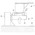
- each transport device 15 has a configuration capable of moving up and down.
- the transport device 15 has, for example, a pedestal 18 on which the holding jig 1 is placed, and an elevating unit 19 that ascends and descends while supporting the pedestal 18.
- the pedestal portion 18 is disposed horizontally in the longitudinal direction, and receives the load of the holding jig 1 from the horizontal member 6.
- the pedestal 18 has a conveyor 16, and with the pedestal 18 elevated, the conveyor 16 receives the load of the holding jig 1 and is movably installed along the longitudinal direction. .
- the holding jig 1 placed on the upper surface of the conveyor 16 moves in one direction.
- the movement of the holding jig 1 is also stopped by stopping the conveyor 16 while the holding jig 1 is placed on the upper surface of the conveyor 16.
- the fixing portion 20 is installed adjacent to the transfer device 15.
- the fixing portion 20 is provided corresponding to the four corners of the lower surface of the holding jig 1, and in the example of the holding jig 1 shown in FIGS. 3 and 4, installed directly under the connection portion of the horizontal member 6 and the arch member 7. Be done.
- one fixing unit 20 may be installed between the two conveying devices 15 arranged in series.
- six fixing parts 20 are provided for one holding jig 1.
- the holding jig 1 can be prevented from spreading in four directions, and the shape accuracy of the holding jig 1 Can be secured. Further, the plurality of fixing portions 20 are provided on the installation surface 23, and the holding jig 1 is supported by and fixed to the plurality of fixing portions 20 so that the holding jig 1 is positioned with respect to the installation surface 23 Ru.
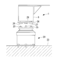
- the fixing portion 20 is provided with a self-aligning clamp 25 (for example, also called a pallet clamp) which protrudes upward in the vertical direction on the upper surface.
- a positioning hole 26 is provided on the lower surface of the horizontal member 6 of the holding jig 1 corresponding to the automatic alignment clamp 25 of the fixed portion 20.
- the automatic alignment clamp 25 has a positioning function of moving the positioning hole 26 to a predetermined position in the horizontal plane and a predetermined position in the height direction with respect to the automatic alignment clamp 25 by fitting with the positioning hole 26. Therefore, when the self-aligning clamp 25 and the positioning hole 26 are fitted, it is possible to define the position in the horizontal plane and the position in the vertical direction of the holding jig 1 with respect to the fixing portion 20. Further, the automatic alignment clamp 25 also has a clamp function of fixing so that the positioning hole 26 does not come out when the positioning hole 26 is fitted.
- a rough guide 27 is provided on the upper surface of the fixing portion 20, and a guide hole 28 is provided on the lower surface of the horizontal member 6 of the holding jig 1.
- the rough guide 27 is, for example, a rod-like member, and is provided vertically to the upper surface of the fixed portion 20. The rough guide 27 can be inserted through the guide hole 28, and the holding jig 1 can be moved along the rough guide 27.
- the hole diameter of the guide hole 28 is, for example, a size obtained by adding an allowance to the extent that the self alignment clamp 25 or the positioning hole 26 does not contact with the diameter of the rough guide 27.
- a plurality of fixing portions 20 are arranged as described above, but as shown in FIG. 10, the holding jig fixing device 2 may be configured by mutually connecting with the girder members 29. Thereby, the fluctuation
- FIG. 11 shows a state in which the holding jig 1 is placed on the holding jig fixing device 2.
- the distance between the fixing portions 20 is always maintained, the shape of the holding jig 1 supported by the plurality of fixing portions 20 is accurately guaranteed.
- the material of the fixing portion 20 and the material of the holding jig 1 be the same and have the same coefficient of thermal expansion. As a result, even if both thermally expand or thermally shrink due to a change in the environmental temperature of the work space, the positioning of the holding jig 1 is not adversely affected.
- fixed part 20 are not limited to the example mentioned above.
- the installation number and installation position of the fixed part 20 and the installation number and installation position of the automatic alignment clamp 25 are changed according to the weight of the holding jig 1 and the body panel 10 held at the top, the shape of the holding jig 1, etc. Be done.
- the holding jig 1 placed on the carriage is moved to the transfer track, and the hold jig 1 is moved to the transfer track. Then, the holding jig 1 moves between the work spaces along the transport path.
- the movement of the holding jig 1 on the conveyance track is performed, for example, by the conveyor 16 of the conveyance device 15 located at the bottom of the holding jig 1.
- the transport device 15 is in a state in which the pedestal 18 is lifted by the elevating unit 19. At this time, the holding jig 1 and the fixing portion 20 are in a separated positional relationship.
- the conveyor 16 is driven to move the holding jig 1 to a predetermined position in the work space.
- the predetermined position of the work space for example, the self-aligning clamp 25 of the fixed portion 20 and the positioning hole 26 provided on the lower surface of the holding jig 1 are positioned in the vertical relationship, and the central axis is substantially It is a position that matches.
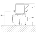
- the holding jig 1 is lowered by the elevating part 19 of the transfer device 15.
- the rough guide 27 is inserted into the guide hole 28 and the holding jig 1 is lowered while guiding the holding jig 1 to the rough guide 27.
- the automatic alignment clamp 25 and the positioning hole 26 of the holding jig 1 come into contact at a shifted position, and damage to the automatic alignment clamp 25 or the positioning hole 26 can be prevented.
- the automatic alignment clamp 25 is fitted in the positioning hole 26. Thereafter, the holding jig 1 is positioned at an accurate position by the automatic alignment mechanism of the automatic alignment clamp 25. Further, the holding jig 1 and the fixing portion 20 are firmly fixed to each other by the clamp mechanism of the automatic alignment clamp 25.
- the plurality of fixing portions 20 are provided on the installation surface 23, and the holding jig 1 is positioned relative to the installation surface 23 by being supported and fixed by the plurality of fixing portions 20.
- the plurality of fixing portions 20 are provided corresponding to the four corner portions of the lower surface of the holding jig 1 and provided between two conveying devices 15 arranged in series, and installed at a total of six positions.
- the holding jig 1 can be prevented from spreading in four directions, and the shape accuracy of the holding jig 1 can be secured.
- the fixing by the clamp mechanism of the automatic alignment clamp 25 is released, and the holding jig 1 is raised by the elevating unit 19 of the transfer device 15.
- the holding jig 1 and the fixing portion 20 have a separated positional relationship.
- the movement of the holding jig 1 on the transfer track is performed by the conveyor 16 of the transfer device 15.
- the holding jig 1 is moved to the adjacent work space.
- FIG.12 and FIG.13 the installation method of the automatic alignment clamp 25 of the several fixing
- the automatic alignment clamps 25 of the fixed unit 20 are installed so that the positional relationship of the automatic alignment clamps 25 of the plurality of fixed units 20 is unified in each work space.
- the holding jig 1 is transported between the work spaces and fixed in each work space
- the conventional positioning jig in which the jig is once installed and the position accuracy and the shape accuracy are guaranteed Equivalent accuracy can be guaranteed.
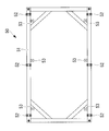
- the reference jig 50 is disposed on the plurality of fixing portions 20 of each work space.
- the automatic alignment clamp 25 is installed at a predetermined position on the plurality of fixing portions 20.
- the reference jig 50 includes, for example, a square-shaped integral frame member 51, and the frame member 51 is provided with a plurality of coupling portions 52 and positioning portions 53.
- the plurality of coupling portions 52 are provided on the lower surface of the frame member 51 and have a configuration capable of being coupled to the automatic alignment clamp 25 of the fixing portion 20.
- the coupling portion 52 is provided at a position corresponding to the automatic alignment clamp 25 installed on the fixing portion 20.
- a plurality of positioning portions 53 are provided on the inner side surface of the frame member 51.
- the positioning portion 53 of the reference jig 50 is provided at a position corresponding to the positioning portion provided in the holding jig fixing device 2, and the position with the positioning portion 55 (see FIG. 13) provided in the holding jig fixing device 2. It has a configuration that can be combined.
- a fixed portion 20 in which the automatic alignment clamp 25 and the rough guide 27 are not installed is made to connect a member (not shown) in which the automatic alignment clamp 25 and the rough guide 27 are integrated with the connecting portion 52 of the reference jig 50.
- the reference jig 50 is arranged on the upper part of.
- the positioning portion 53 of the reference jig 50 is aligned with the positioning portion 55 provided in the holding jig fixing device 2. Then, a member in which the automatic alignment clamp 25 and the rough guide 27 are integrated is fixed on the fixing portion 20 using a tool or the like. Thereafter, from the connecting portion 52 of the reference jig 50, the connection of the member in which the self-aligning clamp 25 and the rough guide 27 are integrated is released. This work is performed in a plurality of fixed parts 20 in one work space.
- the installation position of the member in which the automatic alignment clamp 25 and the rough guide 27 are integrated is accurately determined, and as a result, in one work space, the positional relationship of the automatic alignment clamps 25 of the plurality of fixing portions 20 simultaneously It is determined.
- the same reference jig 50 is moved to another work space, and the automatic alignment clamp 25 is fixed on the fixing portion 20 in the same procedure as the above-described operation.
- the positional relationship of the plurality of automatic alignment clamps 25 is unified and installed in each work space.
- the positional accuracy of the holding jig fixing device 2 is confirmed by reading a marker attached to the fixing portion 20 or the like with a laser tracker or the like.
- the fixing unit 20 is reinstalled using the reference jig 50.
- the positional accuracy of not only the fixing portion 20 but also all the reference points provided in the holding jig fixing device 2 is measured in more detail using a laser tracker or the like. At this time, if necessary, the holding jig 1 and the fixing portion 20 may be corrected so as to have necessary accuracy.
- the automatic alignment clamp 25 is provided on a stage mechanism movable in two orthogonal axial directions.
- the stage mechanism includes, for example, a stage portion, a linear guide, a stopper, and a ball screw mechanism.
- the stage unit includes, for example, a first stage unit 31 movable in one direction (X direction), and a second stage unit 32 movable in the vertical direction (Y direction) with respect to one direction.
- the portion 31 and the second stage portion 32 are located in an up and down relationship and are parallel to each other.
- the first stage portion 31 is disposed on the main body portion 30 of the fixed portion 22 via the linear guide 33 for moving the first stage portion 31 in the X direction, and the second stage portion 32 It is installed on the first stage portion 31 via a linear guide 34 which is moved in the direction.
- An automatic alignment clamp 25 and a rough guide 27 are installed on the second stage portion 32. As the first stage portion 31 moves in the X direction and the second stage portion 32 moves in the Y direction, the self-aligning clamp 25 and the rough guide 27 become movable in the XY plane.
- the stopper (not shown) fixes the positions of the first stage portion 31 and the second stage portion 32 whose positions have been adjusted.
- the automatic alignment clamp 25 and the rough guide 27 are fixed by the stopper via the first stage portion 31 and the second stage portion 32, there is a possibility that the position may be changed by daily repetitive work. In this case, for example, by measuring the position of the second stage portion 32, it may be inspected whether the positions of the automatic alignment clamp 25 and the rough guide 27 are at appropriate positions and the position adjustment may be performed.
- the measurement of the position of the second stage portion 32 is, for example, a laser tracker 41 which is installed at a position separated from the fixed portion 22 and which emits laser light and receives reflected light from the reflector 42; This is performed by the reflector 42 and the control unit 43.
- the laser tracker 41 emits a laser beam and receives the laser beam reflected by the reflector 42 provided on the second stage unit 32, thereby detecting the position of the second stage unit 32.
- the control unit 43 drives the motor 36 of the first ball screw mechanism 35 for moving the first stage portion 31 based on the detected position of the second stage portion 32 so that the first stage portion 31 can be moved in the X direction.
- the second stage portion 32 is moved in the Y direction by driving the motor 38 of the second ball screw mechanism 37 that moves the second stage portion 32.
- the positions of the automatic alignment clamp 25 and the rough guide 27 can be changed.
- the position of the automatic alignment clamp 25 and the rough guide 27 change due to the repeated attachment and detachment of the holding jig 1, the position can be adjusted before the start of the work, etc., and high accuracy positioning and shape retention can be performed regularly. It can be done simply and quickly.
- the automatic alignment clamp 25 and the rough guide 27 are provided on the fixing portions 20 and 22, and the positioning hole 26 and the guide hole 28 are provided on the holding jig 1.
- the present invention is not limited to this example. Contrary to this example, a self-aligning clamp or rough guide may be provided in the holding jig 1, and a positioning hole and a guide hole may be provided in the fixing portions 20 and 22.
- the plurality of fixing portions 22 may be connected by the girder members 29, respectively.
Abstract
Priority Applications (5)
| Application Number | Priority Date | Filing Date | Title |
|---|---|---|---|
| BR112018015496A BR112018015496A2 (pt) | 2016-02-02 | 2016-11-17 | aparelho de fixação do dispositivo de retenção |
| CA3013175A CA3013175C (fr) | 2016-02-02 | 2016-11-17 | Appareil de fixation d'un appareil de maintien |
| US16/073,098 US11034464B2 (en) | 2016-02-02 | 2016-11-17 | Holding fixture fixing apparatus |
| CN201680079979.3A CN108495790A (zh) | 2016-02-02 | 2016-11-17 | 保持型架固定装置 |
| EP16889381.6A EP3412581A4 (fr) | 2016-02-02 | 2016-11-17 | Dispositif de fixation de gabarit de maintien |
Applications Claiming Priority (2)
| Application Number | Priority Date | Filing Date | Title |
|---|---|---|---|
| JP2016-018425 | 2016-02-02 | ||
| JP2016018425A JP6513584B2 (ja) | 2016-02-02 | 2016-02-02 | 保持治具固定装置 |
Publications (1)
| Publication Number | Publication Date |
|---|---|
| WO2017134898A1 true WO2017134898A1 (fr) | 2017-08-10 |
Family
ID=59499705
Family Applications (1)
| Application Number | Title | Priority Date | Filing Date |
|---|---|---|---|
| PCT/JP2016/084047 WO2017134898A1 (fr) | 2016-02-02 | 2016-11-17 | Dispositif de fixation de gabarit de maintien |
Country Status (7)
| Country | Link |
|---|---|
| US (1) | US11034464B2 (fr) |
| EP (1) | EP3412581A4 (fr) |
| JP (1) | JP6513584B2 (fr) |
| CN (1) | CN108495790A (fr) |
| BR (1) | BR112018015496A2 (fr) |
| CA (1) | CA3013175C (fr) |
| WO (1) | WO2017134898A1 (fr) |
Cited By (2)
| Publication number | Priority date | Publication date | Assignee | Title |
|---|---|---|---|---|
| CN107585324A (zh) * | 2017-10-11 | 2018-01-16 | 重庆通用飞机工业有限公司 | 一种直升机尾梁装配架 |
| FR3086268A1 (fr) * | 2018-09-25 | 2020-03-27 | Airbus Operations | Procede d’assemblage d’un troncon de fuselage d’aeronef a partir de deux parties superieure et inferieure superposees, support de montage polyvalent, outillage et unite de production de troncons de fuselage pour la mise en œuvre dudit procede |
Families Citing this family (4)
| Publication number | Priority date | Publication date | Assignee | Title |
|---|---|---|---|---|
| CN108791950B (zh) * | 2018-06-26 | 2023-12-29 | 中电科芜湖钻石飞机制造有限公司 | 飞机大型部件装配用装配设备 |
| US11827380B2 (en) * | 2021-01-26 | 2023-11-28 | The Boeing Company | System and method for positioning a sub-assembly for installation |
| CN112935873B (zh) * | 2021-02-05 | 2022-05-31 | 中国十七冶集团有限公司 | 一种异型钢结构弯扭构件用辅助定位系统及其定位方法 |
| US11866201B2 (en) | 2022-05-03 | 2024-01-09 | The Boeing Company | Method and apparatus for the application of frame to fuselage pull-up force via fuselage skin waterline tensioning |
Citations (5)
| Publication number | Priority date | Publication date | Assignee | Title |
|---|---|---|---|---|
| JPS6464740A (en) * | 1987-04-14 | 1989-03-10 | Northrop Corp | Built-up data model system |
| US5649888A (en) * | 1992-10-13 | 1997-07-22 | The Boeing Company | System for making a panel |
| JP2011208992A (ja) * | 2010-03-29 | 2011-10-20 | Ntn Corp | 空間座標測定システムおよび空間座標測定方法 |
| JP2013198918A (ja) * | 2012-03-23 | 2013-10-03 | Mitsubishi Heavy Ind Ltd | 自動打鋲装置 |
| EP2792431A1 (fr) * | 2013-04-16 | 2014-10-22 | Brötje-Automation GmbH | Installation de traitement pour des composants de structure d'avion |
Family Cites Families (19)
| Publication number | Priority date | Publication date | Assignee | Title |
|---|---|---|---|---|
| US4937768A (en) | 1987-04-14 | 1990-06-26 | Northrop Corporation | Integrated assembly system |
| JP2518088B2 (ja) | 1990-05-18 | 1996-07-24 | 三菱自動車工業株式会社 | 車両のアクセル全閉位置検出装置 |
| US6314630B1 (en) | 1996-03-22 | 2001-11-13 | The Boeing Company | Determinant wing assembly |
| ES2146140B1 (es) * | 1996-10-15 | 2001-04-01 | Torres Martinez M | Maquina para el soporte y mecanizado de piezas. |
| US6505393B2 (en) | 1998-07-31 | 2003-01-14 | Airbus Deutschland Gmbh | Two-part riveting apparatus and method for riveting barrel-shaped components such as aircraft fuselage components |
| ES2169620B1 (es) * | 1999-01-22 | 2003-11-01 | Torres Ingenieria De Procesos | Util para el montaje de secciones del fuselaje de aeronaves. |
| DE102004056284B4 (de) * | 2004-11-22 | 2010-08-26 | Airbus Deutschland Gmbh | Vorrichtung zum Transport von Bauteilen für Verkehrsmittel |
| JP2006247757A (ja) | 2005-03-08 | 2006-09-21 | Toyota Industries Corp | ワーク保持装置及びワーク保持方法 |
| CN100565406C (zh) * | 2008-09-19 | 2009-12-02 | 浙江大学 | 一种基于四个定位器的飞机部件位姿调整系统及方法 |
| CN101537887A (zh) | 2009-03-17 | 2009-09-23 | 成都飞机工业(集团)有限责任公司 | 一种机身三点浮动入位方法 |
| EP3184433B1 (fr) * | 2010-06-14 | 2018-07-25 | LORD Corporation | Système et procédés de pose de moteur d'hélicoptère |
| CN102001451B (zh) * | 2010-11-12 | 2013-05-29 | 浙江大学 | 基于四个数控定位器、调姿平台和移动托架的飞机部件调姿、对接系统及方法 |
| JP5943557B2 (ja) * | 2011-06-01 | 2016-07-05 | キヤノン株式会社 | 位置決め装置、露光装置およびデバイス製造方法 |
| CN103465039A (zh) | 2013-02-27 | 2013-12-25 | 中航飞机股份有限公司西安飞机分公司 | 一种可实现多自由度运动的调姿连接机构 |
| JP6219055B2 (ja) | 2013-03-29 | 2017-10-25 | 三菱重工業株式会社 | 機体結合方法及びストロングバック |
| FR3016606B1 (fr) * | 2014-01-21 | 2016-02-19 | Airbus Operations Sas | Procede de fabrication d'une partie d'un fuselage d'un aeronef et outillage pour la mise en oeuvre dudit procede |
| US10525524B2 (en) * | 2014-07-09 | 2020-01-07 | The Boeing Company | Dual-interface coupler |
| CN104229158B (zh) | 2014-09-03 | 2016-05-25 | 上海交通大学 | 用于大型筒状薄壁构件自动装配的六自由度定位调姿装备 |
| CN105109706B (zh) * | 2015-08-26 | 2017-05-31 | 西北工业大学 | 一种用于飞机薄壁件定位夹持实验装置 |
-
2016
- 2016-02-02 JP JP2016018425A patent/JP6513584B2/ja active Active
- 2016-11-17 CA CA3013175A patent/CA3013175C/fr active Active
- 2016-11-17 BR BR112018015496A patent/BR112018015496A2/pt not_active Application Discontinuation
- 2016-11-17 EP EP16889381.6A patent/EP3412581A4/fr not_active Withdrawn
- 2016-11-17 US US16/073,098 patent/US11034464B2/en active Active
- 2016-11-17 CN CN201680079979.3A patent/CN108495790A/zh active Pending
- 2016-11-17 WO PCT/JP2016/084047 patent/WO2017134898A1/fr active Application Filing
Patent Citations (5)
| Publication number | Priority date | Publication date | Assignee | Title |
|---|---|---|---|---|
| JPS6464740A (en) * | 1987-04-14 | 1989-03-10 | Northrop Corp | Built-up data model system |
| US5649888A (en) * | 1992-10-13 | 1997-07-22 | The Boeing Company | System for making a panel |
| JP2011208992A (ja) * | 2010-03-29 | 2011-10-20 | Ntn Corp | 空間座標測定システムおよび空間座標測定方法 |
| JP2013198918A (ja) * | 2012-03-23 | 2013-10-03 | Mitsubishi Heavy Ind Ltd | 自動打鋲装置 |
| EP2792431A1 (fr) * | 2013-04-16 | 2014-10-22 | Brötje-Automation GmbH | Installation de traitement pour des composants de structure d'avion |
Non-Patent Citations (1)
| Title |
|---|
| See also references of EP3412581A4 * |
Cited By (3)
| Publication number | Priority date | Publication date | Assignee | Title |
|---|---|---|---|---|
| CN107585324A (zh) * | 2017-10-11 | 2018-01-16 | 重庆通用飞机工业有限公司 | 一种直升机尾梁装配架 |
| FR3086268A1 (fr) * | 2018-09-25 | 2020-03-27 | Airbus Operations | Procede d’assemblage d’un troncon de fuselage d’aeronef a partir de deux parties superieure et inferieure superposees, support de montage polyvalent, outillage et unite de production de troncons de fuselage pour la mise en œuvre dudit procede |
| EP3628599A1 (fr) * | 2018-09-25 | 2020-04-01 | Airbus Operations | Procédé, outillage et unité de production de tronçons de fuselage d'aéronef |
Also Published As
| Publication number | Publication date |
|---|---|
| EP3412581A4 (fr) | 2019-07-24 |
| CA3013175A1 (fr) | 2017-08-10 |
| EP3412581A1 (fr) | 2018-12-12 |
| BR112018015496A2 (pt) | 2018-12-18 |
| CA3013175C (fr) | 2020-08-25 |
| JP6513584B2 (ja) | 2019-05-15 |
| JP2017136928A (ja) | 2017-08-10 |
| CN108495790A (zh) | 2018-09-04 |
| US20190031372A1 (en) | 2019-01-31 |
| US11034464B2 (en) | 2021-06-15 |
Similar Documents
| Publication | Publication Date | Title |
|---|---|---|
| JP6513584B2 (ja) | 保持治具固定装置 | |
| JP6513585B2 (ja) | 形状保持治具及び航空機パネル製造方法 | |
| JP6650147B2 (ja) | 航空機パネル製造方法及び航空機パネル製造システム | |
| US11235954B2 (en) | Alignment device and method for mounting a guide rail in an elevator shaft of an elevator system | |
| US20200055709A1 (en) | Method for mounting and alignment device for aligning a guide rail of an elevator system | |
| KR101989622B1 (ko) | 합판 운반장치 | |
| CA2987024A1 (fr) | Dispositif de fabrication d'ensemble et procede de fabrication d'ensemble | |
| WO2017134902A1 (fr) | Gabarit de maintien | |
| JP2006242679A (ja) | 基板検査装置及び基板検査装置の組み立て方法 | |
| JP3094709B2 (ja) | 車両の下回り部品組付けライン | |
| JP2016044621A (ja) | 航空機エンジンの取り付け方法 | |
| US7334673B2 (en) | System and method for machining elongate members | |
| KR102126558B1 (ko) | 크레인의 새들 조립용 지그장치 및 이를 이용한 크레인 세팅 및 검사방법 | |
| JPH0592812A (ja) | パレツト位置決め構造 | |
| CN110064903B (zh) | 扶梯导轨系统安装方法及定位工装 | |
| JP6487291B2 (ja) | 搬送装置、及び、この搬送装置を用いる搬送システム | |
| JPH1134863A (ja) | レール装置 | |
| CN103612964A (zh) | 施工升降机标准节齿条垫块的上料定位工装及自动焊接装置 |
Legal Events
| Date | Code | Title | Description |
|---|---|---|---|
| 121 | Ep: the epo has been informed by wipo that ep was designated in this application |
Ref document number: 16889381 Country of ref document: EP Kind code of ref document: A1 |
|
| WWE | Wipo information: entry into national phase |
Ref document number: 3013175 Country of ref document: CA |
|
| NENP | Non-entry into the national phase |
Ref country code: DE |
|
| REG | Reference to national code |
Ref country code: BR Ref legal event code: B01A Ref document number: 112018015496 Country of ref document: BR |
|
| WWE | Wipo information: entry into national phase |
Ref document number: 2016889381 Country of ref document: EP |
|
| ENP | Entry into the national phase |
Ref document number: 2016889381 Country of ref document: EP Effective date: 20180903 |
|
| ENP | Entry into the national phase |
Ref document number: 112018015496 Country of ref document: BR Kind code of ref document: A2 Effective date: 20180730 |