WO2017130840A1 - サンルーフ装置 - Google Patents
サンルーフ装置 Download PDFInfo
- Publication number
- WO2017130840A1 WO2017130840A1 PCT/JP2017/001798 JP2017001798W WO2017130840A1 WO 2017130840 A1 WO2017130840 A1 WO 2017130840A1 JP 2017001798 W JP2017001798 W JP 2017001798W WO 2017130840 A1 WO2017130840 A1 WO 2017130840A1
- Authority
- WO
- WIPO (PCT)
- Prior art keywords
- base panel
- washer
- panel
- sunroof
- sunroof device
- Prior art date
- Legal status (The legal status is an assumption and is not a legal conclusion. Google has not performed a legal analysis and makes no representation as to the accuracy of the status listed.)
- Ceased
Links
Images


Classifications
-
- B—PERFORMING OPERATIONS; TRANSPORTING
- B60—VEHICLES IN GENERAL
- B60J—WINDOWS, WINDSCREENS, NON-FIXED ROOFS, DOORS, OR SIMILAR DEVICES FOR VEHICLES; REMOVABLE EXTERNAL PROTECTIVE COVERINGS SPECIALLY ADAPTED FOR VEHICLES
- B60J7/00—Non-fixed roofs; Roofs with movable panels, e.g. rotary sunroofs
- B60J7/02—Non-fixed roofs; Roofs with movable panels, e.g. rotary sunroofs of sliding type, e.g. comprising guide shoes
- B60J7/04—Non-fixed roofs; Roofs with movable panels, e.g. rotary sunroofs of sliding type, e.g. comprising guide shoes with rigid plate-like element or elements, e.g. open roofs with harmonica-type folding rigid panels
- B60J7/043—Sunroofs e.g. sliding above the roof
-
- B—PERFORMING OPERATIONS; TRANSPORTING
- B60—VEHICLES IN GENERAL
- B60J—WINDOWS, WINDSCREENS, NON-FIXED ROOFS, DOORS, OR SIMILAR DEVICES FOR VEHICLES; REMOVABLE EXTERNAL PROTECTIVE COVERINGS SPECIALLY ADAPTED FOR VEHICLES
- B60J7/00—Non-fixed roofs; Roofs with movable panels, e.g. rotary sunroofs
- B60J7/02—Non-fixed roofs; Roofs with movable panels, e.g. rotary sunroofs of sliding type, e.g. comprising guide shoes
- B60J7/022—Sliding roof trays or assemblies
-
- B—PERFORMING OPERATIONS; TRANSPORTING
- B60—VEHICLES IN GENERAL
- B60J—WINDOWS, WINDSCREENS, NON-FIXED ROOFS, DOORS, OR SIMILAR DEVICES FOR VEHICLES; REMOVABLE EXTERNAL PROTECTIVE COVERINGS SPECIALLY ADAPTED FOR VEHICLES
- B60J7/00—Non-fixed roofs; Roofs with movable panels, e.g. rotary sunroofs
- B60J7/02—Non-fixed roofs; Roofs with movable panels, e.g. rotary sunroofs of sliding type, e.g. comprising guide shoes
-
- B—PERFORMING OPERATIONS; TRANSPORTING
- B60—VEHICLES IN GENERAL
- B60J—WINDOWS, WINDSCREENS, NON-FIXED ROOFS, DOORS, OR SIMILAR DEVICES FOR VEHICLES; REMOVABLE EXTERNAL PROTECTIVE COVERINGS SPECIALLY ADAPTED FOR VEHICLES
- B60J7/00—Non-fixed roofs; Roofs with movable panels, e.g. rotary sunroofs
- B60J7/02—Non-fixed roofs; Roofs with movable panels, e.g. rotary sunroofs of sliding type, e.g. comprising guide shoes
- B60J7/04—Non-fixed roofs; Roofs with movable panels, e.g. rotary sunroofs of sliding type, e.g. comprising guide shoes with rigid plate-like element or elements, e.g. open roofs with harmonica-type folding rigid panels
- B60J7/047—Non-fixed roofs; Roofs with movable panels, e.g. rotary sunroofs of sliding type, e.g. comprising guide shoes with rigid plate-like element or elements, e.g. open roofs with harmonica-type folding rigid panels movable to overlapping or nested relationship
-
- B—PERFORMING OPERATIONS; TRANSPORTING
- B62—LAND VEHICLES FOR TRAVELLING OTHERWISE THAN ON RAILS
- B62D—MOTOR VEHICLES; TRAILERS
- B62D25/00—Superstructure or monocoque structure sub-units; Parts or details thereof not otherwise provided for
- B62D25/06—Fixed roofs
-
- F—MECHANICAL ENGINEERING; LIGHTING; HEATING; WEAPONS; BLASTING
- F16—ENGINEERING ELEMENTS AND UNITS; GENERAL MEASURES FOR PRODUCING AND MAINTAINING EFFECTIVE FUNCTIONING OF MACHINES OR INSTALLATIONS; THERMAL INSULATION IN GENERAL
- F16B—DEVICES FOR FASTENING OR SECURING CONSTRUCTIONAL ELEMENTS OR MACHINE PARTS TOGETHER, e.g. NAILS, BOLTS, CIRCLIPS, CLAMPS, CLIPS OR WEDGES; JOINTS OR JOINTING
- F16B5/00—Joining sheets or plates, e.g. panels, to one another or to strips or bars parallel to them
- F16B5/02—Joining sheets or plates, e.g. panels, to one another or to strips or bars parallel to them by means of fastening members using screw-thread
Definitions
- the present invention relates to a sunroof device.
- Such a sunroof device includes a base panel (roof frame) installed on the body of a vehicle.
- the base panel As a material of the base panel, only an iron plate, only a resin, a combination of an iron plate and a resin, or the like is adopted. Then, the base panel is fixed to the vehicle body with bolt fastening or an adhesive.
- the material of the base panel is only an iron plate
- the increase in the mass of the base panel necessitates a deterioration in fuel consumption or an increase in the center of gravity of the vehicle and a decrease in running stability.
- the material of the base panel is only resin
- the base panel must be enlarged in order to ensure sufficient rigidity.
- the material of the base panel is a combination of an iron plate and a resin, for example, it is manufactured by insert molding, so that the number of manufacturing steps is inevitably increased.
- An object of the present invention is to provide a sunroof device that can be further reduced in weight.
- a sunroof device that solves the above problems includes a base panel made of aluminum alloy that is installed at the periphery of an opening formed in a vehicle body, a sunroof unit that is attached to the base panel, and an upper part of the base panel. And a panel connected to the sunroof unit.
- the entire sunroof device can be further reduced in weight compared to a case where the base panel is made of, for example, iron.
- the sunroof device has a head portion facing the base panel, further comprising an iron fastener for fastening the peripheral portion of the opening and the base panel, and a resin film between the base panel and the head portion. It is preferable to be interposed.
- the said resin film is interposed between the said base panel and the said head, and can suppress the corrosion by the contact of dissimilar metals.
- the resin film is preferably an adhesive or a coating film covering the head.
- the head fastener
- the resin film is the coating film
- the resin film can be formed by a simple operation of painting the head.
- an iron washer placed on the base panel, an iron bolt having a head portion welded to the washer, and a peripheral portion of the opening and a shaft portion penetrating the base panel; And a nut for fastening the peripheral edge of the opening and the base panel in cooperation with the head by screwing into the shaft, and a resin film is interposed between the base panel and the washer It is preferable.
- the said resin film is a coating film which covers an adhesive agent or the said washer. According to this configuration, for example, if the resin film is the adhesive, the washer and the bolt can be prevented from rotating. On the other hand, if the resin film is the coating film, the resin film can be formed by a simple operation of coating the washer.
- the sunroof device further includes a plurality of fastening members that fasten the washer to the base panel at different locations.
- the washer and the bolt can be further prevented from rotating by fastening the washer to the base panel at a plurality of locations by the plurality of fastening members.
- the present invention has the effect of reducing the weight of the sunroof device.
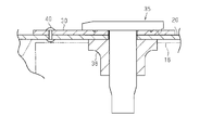
- FIG. 3 is a cross-sectional view taken along line 3-3 in FIG. 2. Sectional drawing equivalent to FIG. 3 which shows the sunroof apparatus of the modification of this invention.
- front-rear direction of the vehicle is referred to as “front-rear direction”
- upper direction and the lower direction of the vehicle height are referred to as “upward” and “lower”, respectively.
- a substantially rectangular opening 11 is formed in a roof 10 of a vehicle such as an automobile, and a front roof panel 12, a center roof panel 13 as a panel, and a rear
- the roof panel 14 is juxtaposed in the front-rear direction.
- the front roof panel 12, the center roof panel 13, and the rear roof panel 14 are all substantially rectangular, and are made of, for example, glass or resin.
- the front roof panel 12 and the rear roof panel 14 are attached so as to always close the front part and the rear part of the opening 11 respectively.
- the center roof panel 13 is attached so that the front-rear direction center part of the opening 11 can be opened and closed.
- the center roof panel 13 is attached so that a tilt-up operation in which the rear portion rises with the front portion as a fulcrum and a slide operation in the front-rear direction are possible.
- a so-called outer sliding type is employed in which the sliding operation is performed in the tilted-up state.
- the roof 10 has an iron inner panel 15 that forms the peripheral edge of the opening 11.
- the inner panel 15 has a substantially flange-shaped attachment piece 16 extending toward the center of the opening 11 over substantially the entire periphery of the opening 11, and a resin coating film is formed on at least the upper surface of the attachment piece 16. Is formed.
- the base panel 20 which consists of a press material of the single plate made from aluminum alloy is arrange
- the base panel 20 includes a pair of side frames 21, a front frame 22, and a rear frame 23 that extend along both sides of the vehicle in the width direction of the opening 11, a front edge, and a rear edge, respectively.
- An intermediate frame 24 extending in the width direction of the vehicle is connected to connect the front and rear intermediate portions of the side frames 21. That is, the base panel 20 has a square frame-shaped portion formed by the both side frames 21, the front frame 22 and the rear frame 23. The base panel 20 is placed and fixed to the mounting piece 16 of the inner panel 15 in each of the side frame 21, the front frame 22, and the rear frame 23.
- the sunroof unit 25 is attached to the base panel 20.
- the sunroof unit 25 is provided below the base panel 20.
- the sunroof unit 25 includes a pair of guide rails 26 extending in the front-rear direction along both side frames 21 of the base panel 20 and a front housing extending in the vehicle width direction along the front frame 22 of the base panel 20. 27.
- Each guide rail 26 is made of, for example, an extruded material of an aluminum alloy.
- the front housing 27 is made of, for example, a resin material and connects the front ends of both guide rails 26.
- the sunroof unit 25 has a pair of functional parts 28 supported by both guide rails 26 so as to be movable in the front-rear direction.
- the center roof panel 13 is linked to and supported by both functional parts 28 in a state of being bridged between them.
- the center roof panel 13 opens and closes as the functional parts 28 move in the front-rear direction.
- the base panel 20 is placed and fixed on the mounting piece 16 from above in a module state in which the panels 12 to 14 and the sunroof unit 25 are assembled in advance to the base panel 20. Since the structures for mounting and fixing the side frame 21, the front frame 22, and the rear frame 23 to the mounting piece 16 are equivalent to each other, the following description will be given by taking the case of the front frame 22 as a representative.
- FIG. 3 shows a state in which the front frame 22 is overlaid on the mounting piece 16.
- a substantially square plate washer 30 made of iron, for example is placed above the attachment piece 16. That is, the washer 30 is joined to the front frame 22 while being electrically insulated by an adhesive 31 made of urethane resin, for example, interposed between the washer 30 and the front frame 22.
- a head 36 of an iron bolt 35 is placed on the washer 30. That is, the head 36 is joined to the washer 30 by welding, for example.
- the bolt 35 has a shaft portion 37 that extends in the height direction of the vehicle and penetrates the washer 30, the front frame 22, and the attachment piece 16.
- a nut 38 is screwed onto the shaft portion 37 of the bolt 35 that passes through the washer 30, the front frame 22, and the mounting piece 16 downward. Thereby, the attachment piece 16 and the front frame 22 are fastened by the cooperation of the head 36 and the nut 38 via the washer 30.
- the nut 38 is made of, for example, iron, and a resin coating film is formed on the upper surface of the nut 38.
- the fastening of the attachment piece 16 and the front frame 22 is similarly performed by bolts 35, nuts 38, and the like at a plurality of positions spaced in the extending direction of the front frame 22. It is said that the base panel 20 is fastened to the mounting piece 16 in the same manner at a plurality of positions spaced in the extending direction of the rear frame 23 and at a plurality of positions spaced in the extending direction of the side frames 21. Not too long. That is, the base panel 20 assembled to the attachment piece 16 from above is attached to the attachment piece 16 (inner panel 15) by tightening the nut 38 from below on each of the shaft portions 37 of the plurality of bolts 35 penetrating the attachment piece 16. Placed.
- the entire sunroof device can be further reduced in weight as compared with a case where the base panel 20 is made of, for example, iron.
- the base panel 20 is made of, for example, iron.
- the adhesive 31 is interposed between the base panel 20 and the washer 30, so that corrosion due to contact between different metals can be suppressed. Further, by providing the washer 30 between the head portion 36 of the bolt 35 and the base panel 20, the washer 30 comes into contact with the base panel 20 in a wide area to generate a high frictional force. When the base panel 20 is fastened, the rotation of the bolt 35 can be suppressed.
- the washer 30 and the bolt 35 can be prevented from rotating by the adhesive 31 being interposed between the base panel 20 and the washer 30.
- the base panel 20 is made of a single plate press material made of an aluminum alloy, so that the number of parts can be reduced.
- a normal roof made of an aluminum alloy without a sunroof is attached to a roof (inner panel) having a structure according to the roof 10 using an adhesive. Accordingly, since the base panel 20 is made of an aluminum alloy, the base panel 20 can be attached to the roof 10 by using the same production line as that for attaching the normal roof. Manufacturing man-hours and costs can be reduced as compared with the case of newly installing the system.
- a caulking pin 40 as a fastening member may be provided between the washer 30 and the base panel 20, and the washer 30 may be fastened to the base panel 20 using the caulking pin 40.
- the adhesive 31 may be omitted or the adhesive 31 may not be omitted.
- the caulking pin 40 is provided without omitting the adhesive 31, the washer 30 and the bolt 35 can be further prevented from rotating.
- the caulking pins 40 are preferably provided at a plurality of locations on the washer 30. Also in this case, the washer 30 and the bolt 35 can be further prevented from rotating.
- a resin coating film as a resin film may be formed on the lower surface of the washer 30 instead of or in addition to the adhesive 31.
- a resin film interposed between the base panel 20 and the washer 30 can be formed by a simple operation of painting the washer 30.
- an iron caulking pin may be used instead of the bolt 35 and the nut 38. Even in this case, it is preferable to weld the head portion of the caulking pin to the washer 30.
- the washer 30 may be omitted.
- a resin coating film as a resin film (covering the head portion 36) is formed on the lower surface of the head portion 36 of the bolt 35 as a fastener that directly contacts the base panel 20. What is necessary is just to make it electrically isolate between the parts 36.
- a resin film interposed between the base panel 20 and the head 36 can be formed by a simple operation of painting the head 36.
- an adhesive made of urethane resin as a resin film is interposed between the base panel 20 and the lower surface of the head portion 36 of the bolt 35 that is in direct contact with the base panel 20.
- the space may be electrically insulated. In this case, the head 36 (bolt 35) can be prevented from rotating.
- the base panel 20 may be attached to the mounting piece 16 over the entire circumference with, for example, an adhesive made of urethane resin.
- an adhesive made of urethane resin In this case, the rigidity of the sunroof device can be improved by increasing the bonding strength of the base panel 20 to the mounting piece 16, or the water tightness can be increased.
- the base panel 20 to which the sunroof unit 25 is attached may have a rectangular frame shape. That is, the intermediate frame 24 may be omitted.
- the front roof panel 12 may be a deflector panel that performs a tilt-up operation in conjunction with the opening operation of the center roof panel 13.
- the center roof panel 13 may be a fixed panel that always closes the opening 11.
- the rear roof panel 14 may be a movable panel that can open and close the opening 11.
Landscapes
- Engineering & Computer Science (AREA)
- Mechanical Engineering (AREA)
- General Engineering & Computer Science (AREA)
- Chemical & Material Sciences (AREA)
- Combustion & Propulsion (AREA)
- Transportation (AREA)
- Body Structure For Vehicles (AREA)
- Connection Of Plates (AREA)
- Bolts, Nuts, And Washers (AREA)
Abstract
サンルーフ装置は、車両のボデー(10)に形成された開口(11)の周縁部に設置されるアルミニウム合金製のベースパネル(20)と、ベースパネル(20)に取着されるサンルーフユニット(25)と、ベースパネル(20)の上方に配置され、サンルーフユニット(25)に連結されるパネル(13)とを備える。
Description
本発明は、サンルーフ装置に関するものである。
従来、サンルーフ装置として種々のものが提案されている(例えば特許文献1を参照)。こうしたサンルーフ装置は、車両のボデーに設置されるベースパネル(ルーフフレーム)を備える。
ところで、ベースパネルの素材としては、鉄板のみや、樹脂のみ、鉄板及び樹脂の組み合わせなどが採用される。そして、ベースパネルは、車両のボデーに対しボルト締結や接着剤などで固定される。ベースパネルの素材が鉄板のみの場合、ベースパネルの質量が増加することが原因で、燃費が悪化したり車両重心が高くなって走行安定性が低下したりすることを余儀なくされる。一方、ベースパネルの素材が樹脂のみの場合、十分な剛性を確保するためにベースパネルの大型化を余儀なくされる。ベースパネルの素材が鉄板及び樹脂の組み合わせの場合、例えばインサート成形で製造することになるために製造工数の増大を余儀なくされる。
本発明の目的は、より軽量化できるサンルーフ装置を提供することにある。
上記課題を解決するサンルーフ装置は、車両のボデーに形成された開口の周縁部に設置されるアルミニウム合金製のベースパネルと、前記ベースパネルに取着されるサンルーフユニットと、前記ベースパネルの上方に配置され、前記サンルーフユニットに連結されるパネルとを備える。
この構成によれば、前記ベースパネルがアルミニウム合金製であることで、例えば鉄製である場合に比べてサンルーフ装置全体をより軽量化できる。
上記サンルーフ装置について、前記ベースパネルに対向する頭部を有し、前記開口の周縁部及び前記ベースパネルを締結する鉄製の締結具をさらに備え、前記ベースパネル及び前記頭部の間に樹脂膜が介装されることが好ましい。
上記サンルーフ装置について、前記ベースパネルに対向する頭部を有し、前記開口の周縁部及び前記ベースパネルを締結する鉄製の締結具をさらに備え、前記ベースパネル及び前記頭部の間に樹脂膜が介装されることが好ましい。
この構成によれば、前記ベースパネル及び前記頭部の間に前記樹脂膜が介装されることで、異種金属同士の接触による腐食を抑えることができる。
上記サンルーフ装置について、前記樹脂膜は、接着剤又は前記頭部を覆う塗膜であることが好ましい。
上記サンルーフ装置について、前記樹脂膜は、接着剤又は前記頭部を覆う塗膜であることが好ましい。
この構成によれば、例えば前記樹脂膜が前記接着剤であれば、前記頭部(締結具)を回り止めできる。一方、前記樹脂膜が前記塗膜であれば、前記頭部に塗装を施す簡易な作業で前記樹脂膜を形成できる。
上記サンルーフ装置について、前記ベースパネルに載置された鉄製の座金と、前記座金に溶着された頭部を有するとともに、前記開口の周縁部及び前記ベースパネルを貫通する軸部を有する鉄製のボルトと、前記軸部に螺合して前記頭部との協働で前記開口の周縁部及び前記ベースパネルを締結するナットとをさらに備え、前記ベースパネル及び前記座金の間に樹脂膜が介装されることが好ましい。
この構成によれば、前記ベースパネル及び前記座金の間に前記樹脂膜が介装されることで、異種金属同士の接触による腐食を抑えることができる。また、前記頭部及び前記ベースパネルの間に前記座金が設けられていることにより、例えば前記開口の周縁部に対する前記ベースパネルの締結時に前記ボルトの連れ回りを抑制できる。
上記サンルーフ装置について、前記樹脂膜は、接着剤又は前記座金を覆う塗膜であることが好ましい。
この構成によれば、例えば前記樹脂膜が前記接着剤であれば、前記座金及び前記ボルトを回り止めできる。一方、前記樹脂膜が前記塗膜であれば、前記座金に塗装を施す簡易な作業で前記樹脂膜を形成できる。
この構成によれば、例えば前記樹脂膜が前記接着剤であれば、前記座金及び前記ボルトを回り止めできる。一方、前記樹脂膜が前記塗膜であれば、前記座金に塗装を施す簡易な作業で前記樹脂膜を形成できる。
上記サンルーフ装置は、それぞれ互いに異なる箇所において前記座金を前記ベースパネルに締結する複数の締結部材をさらに備えることが好ましい。
この構成によれば、前記複数の締結部材により、前記座金が前記ベースパネルに複数箇所で締結されることで、前記座金及び前記ボルトをいっそう回り止めできる。
この構成によれば、前記複数の締結部材により、前記座金が前記ベースパネルに複数箇所で締結されることで、前記座金及び前記ボルトをいっそう回り止めできる。
本発明は、サンルーフ装置をより軽量化できる効果がある。
以下、本発明の一実施形態のサンルーフ装置について説明する。なお、以下の説明では、車両の前後方向を「前後方向」といい、車両の高さ方向上方及び下方をそれぞれ「上方」及び「下方」という。
図1(a)、(b)に示すように、自動車などの車両のルーフ10には、略四角形の開口11が形成されるとともに、フロントルーフパネル12、パネルとしてのセンタールーフパネル13、及びリヤルーフパネル14が前後方向に並設されている。フロントルーフパネル12、センタールーフパネル13及びリヤルーフパネル14はいずれも略四角形状であり、例えばガラス製又は樹脂製である。フロントルーフパネル12及びリヤルーフパネル14は、開口11の前部及び後部をそれぞれ常時閉塞するように取り付けられている。一方、センタールーフパネル13は、開口11の前後方向中央部を開閉可能に取り付けられている。すなわち、センタールーフパネル13は、その前側部位を支点に後側部位が上昇するチルトアップ作動と前後方向へのスライド作動が可能に取り付けられている。センタールーフパネル13による開閉作動においては、チルトアップ状態のままスライド作動する、いわゆるアウタースライディング式が採用されている。
図2及び図3に示すように、ルーフ10は、開口11の周縁部を形成する鉄製のインナパネル15を有する。このインナパネル15は、開口11の略全周に亘って開口11中心に向かって延出する略フランジ状の取付片16を有しており、少なくとも取付片16の上面に樹脂製の塗膜が形成されている。そして、インナパネル15の上方には、アルミニウム合金製の1枚板のプレス材からなるベースパネル20が配置されている。このベースパネル20は、開口11の車両の幅方向両側縁部、前縁部及び後縁部にそれぞれ沿って延在する一対の側部フレーム21、前部フレーム22及び後部フレーム23を有するとともに、両側部フレーム21の前後方向中間部を接続するべく車両の幅方向に延びる中間フレーム24を有する。つまり、ベースパネル20は、両側部フレーム21、前部フレーム22及び後部フレーム23により形成された四角枠状の部分を有する。そして、ベースパネル20は、両側部フレーム21、前部フレーム22及び後部フレーム23の各々においてインナパネル15の取付片16に載置・固定されている。
ベースパネル20にはサンルーフユニット25が取着されている。サンルーフユニット25は、ベースパネル20の下方に設けられている。サンルーフユニット25は、ベースパネル20の両側部フレーム21に沿って前後方向に延在する一対のガイドレール26と、ベースパネル20の前部フレーム22に沿って車両の幅方向に延在するフロントハウジング27とを有する。各ガイドレール26は、例えばアルミニウム合金の押出材からなる。フロントハウジング27は、例えば樹脂材からなり、両ガイドレール26の前端同士を接続する。
なお、サンルーフユニット25は、両ガイドレール26にそれぞれ前後方向に移動可能に支持された一対の機能部品28を有する。両機能部品28には、それらの間に橋渡しされる状態でセンタールーフパネル13が連係及び支持されている。センタールーフパネル13は、両機能部品28の前後方向の移動に伴って開閉作動する。
次に、インナパネル15の取付片16に対するベースパネル20の載置・固定構造について説明する。なお、ベースパネル20は、パネル12~14及びサンルーフユニット25がベースパネル20に予め組み付けられたモジュールの状態で上方から取付片16に載置・固定されるようになっている。側部フレーム21、前部フレーム22及び後部フレーム23を取付片16に載置・固定する構造については互いに同等であるため、以下では前部フレーム22の場合を代表して説明する。
図3には、取付片16上に前部フレーム22を重ねた状態が示されている。そして、前部フレーム22上には、取付片16の上方で、例えば鉄製の略四角板状の座金30が載置されている。すなわち、座金30は、前部フレーム22との間に介装された、例えばウレタン樹脂製の接着剤31により電気的に絶縁された状態で前部フレーム22に接合されている。また、座金30上には、鉄製のボルト35の頭部36が載置されている。すなわち、頭部36は、例えば溶接にて座金30に接合されている。このボルト35は、車両の高さ方向に軸線が延びて座金30、前部フレーム22及び取付片16を貫通する軸部37を有する。座金30、前部フレーム22及び取付片16を下方に向かって貫通するボルト35の軸部37にはナット38が螺合する。これにより、座金30を介した頭部36及びナット38の協働で取付片16及び前部フレーム22が締結される。ナット38は例えば鉄製であって、ナット38の上面には樹脂製の塗膜が形成されている。
なお、取付片16及び前部フレーム22の締結は、該前部フレーム22の延在方向に間隔をあけた複数箇所で、ボルト35及びナット38等により同様に行われる。後部フレーム23の延在方向に間隔をあけた複数箇所や各側部フレーム21の延在方向に間隔をあけた複数箇所でも同様にして取付片16に対するベースパネル20の締結が行われることはいうまでもない。つまり、取付片16に上方から組み付けられるベースパネル20は、取付片16を貫通する複数のボルト35の軸部37の各々にナット38が下方から締め付けられることで取付片16(インナパネル15)に載置される。
次に、本実施形態の作用とともに、その効果について説明する。
(1)本実施形態では、ベースパネル20がアルミニウム合金製であることで、例えば鉄製である場合に比べてサンルーフ装置全体をより軽量化できる。これにより、車両の燃費の向上と、車両の重心が低くなることで走行安定性の向上とを図ることができる。
(1)本実施形態では、ベースパネル20がアルミニウム合金製であることで、例えば鉄製である場合に比べてサンルーフ装置全体をより軽量化できる。これにより、車両の燃費の向上と、車両の重心が低くなることで走行安定性の向上とを図ることができる。
(2)本実施形態では、ベースパネル20及び座金30の間に接着剤31が介装されることで、異種金属同士の接触による腐食を抑えることができる。また、ボルト35の頭部36及びベースパネル20の間に座金30を設けることにより、ベースパネル20に対して座金30が広い面積で接触して高い摩擦力が生じ、その結果、取付片16に対するベースパネル20の締結時にボルト35の連れ回りを抑制できる。
(3)本実施形態では、ベースパネル20及び座金30の間に接着剤31が介装されることで、座金30及びボルト35を回り止めできる。
(4)本実施形態では、ベースパネル20がアルミニウム合金製の1枚板のプレス材からなることで、部品点数を削減できる。
(4)本実施形態では、ベースパネル20がアルミニウム合金製の1枚板のプレス材からなることで、部品点数を削減できる。
(5)通常、サンルーフ非搭載のアルミニウム合金製のノーマルルーフは、ルーフ10に準じた構造を有するルーフ(インナパネル)に対して接着剤を使って貼着される。従って、ベースパネル20がアルミニウム合金製であることにより、ノーマルルーフを貼着するための生産ラインと同一の生産ラインを利用してベースパネル20をルーフ10に貼着できることになり、別途、生産ラインを新設する場合に比べて製造工数及びコストを削減できる。
なお、上記実施形態は以下のように変更してもよい。
・図4に示すように、座金30及びベースパネル20の間に締結部材としてのカシメピン40を設け、カシメピン40を使って座金30をベースパネル20に締結してもよい。この場合、接着剤31を省略してもよいし、接着剤31を省略しなくてもよい。接着剤31を省略せずにカシメピン40を設けた場合には、座金30及びボルト35をいっそう回り止めできる。カシメピン40は座金30の複数箇所に設けられることが好ましい。この場合も、座金30及びボルト35をいっそう回り止めできる。
・図4に示すように、座金30及びベースパネル20の間に締結部材としてのカシメピン40を設け、カシメピン40を使って座金30をベースパネル20に締結してもよい。この場合、接着剤31を省略してもよいし、接着剤31を省略しなくてもよい。接着剤31を省略せずにカシメピン40を設けた場合には、座金30及びボルト35をいっそう回り止めできる。カシメピン40は座金30の複数箇所に設けられることが好ましい。この場合も、座金30及びボルト35をいっそう回り止めできる。
・前記実施形態において、接着剤31に代えて、若しくは接着剤31に加えて、座金30の下面に(座金30を覆う)樹脂膜としての樹脂製の塗膜を形成してもよい。この場合、座金30に塗装を施す簡易な作業でベースパネル20と座金30との間に介装される樹脂膜を形成できる。
・前記実施形態において、ボルト35及びナット38に代えて、鉄製のカシメピンを採用してもよい。この場合であっても、カシメピンの頭部を座金30に溶着することが好ましい。
・前記実施形態において、座金30を省略してもよい。この場合、ベースパネル20に直に接触する締結具としてのボルト35の頭部36の下面に(頭部36を覆う)樹脂膜としての樹脂製の塗膜を形成して、ベースパネル20と頭部36との間が電気的に絶縁されるようにすればよい。この場合、頭部36に塗装を施す簡易な作業でベースパネル20と頭部36との間に介装される樹脂膜を形成できる。
あるいは、ベースパネル20及びこれに直に接触するボルト35の頭部36の下面との間に、例えば樹脂膜としてのウレタン樹脂製の接着剤を介装して、ベースパネル20と頭部36の間が電気的に絶縁されるようにしてもよい。この場合、頭部36(ボルト35)を回り止めできる。
なお、以上のことは、ボルト35及びナット38に代えて、取付片16及びベースパネル20を締結する鉄製のカシメピンを採用するときに座金30を省略する場合にも同様である。
・前記実施形態において、ベースパネル20は、例えばウレタン樹脂製の接着剤により全周に亘って取付片16に貼着されていてもよい。この場合、取付片16に対するベースパネル20の結合強度が増すことでサンルーフ装置の剛性の向上を図ることができ、あるいは水密性を高めることができる。
・前記実施形態において、サンルーフユニット25の取着されるベースパネル20は四角枠状を呈するものであってもよい。すなわち、中間フレーム24を省略してもよい。
・前記実施形態において、フロントルーフパネル12は、センタールーフパネル13の開作動に連動してチルトアップ作動するデフレクタパネルであってもよい。
・前記実施形態において、フロントルーフパネル12は、センタールーフパネル13の開作動に連動してチルトアップ作動するデフレクタパネルであってもよい。
・前記実施形態において、センタールーフパネル13は、開口11を常時閉塞する固定パネルであってもよい。一方、リヤルーフパネル14は、開口11を開閉可能な可動パネルであってもよい。
11…開口、13…センタールーフパネル(パネル)、16…取付片(周縁部)、20…ベースパネル、25…サンルーフユニット、30…座金、31…接着剤(樹脂膜)、35…ボルト、36…頭部、37…軸部、38…ナット、40…カシメピン(締結部材)。
Claims (6)
- 車両のボデーに形成された開口の周縁部に設置されるアルミニウム合金製のベースパネルと、
前記ベースパネルに取着されるサンルーフユニットと、
前記ベースパネルの上方に配置され、前記サンルーフユニットに連結されるパネルとを備えた、サンルーフ装置。 - 請求項1に記載のサンルーフ装置において、
前記ベースパネルに対向する頭部を有し、前記開口の周縁部及び前記ベースパネルを締結する鉄製の締結具をさらに備え、
前記ベースパネル及び前記頭部の間に樹脂膜が介装された、サンルーフ装置。 - 請求項2に記載のサンルーフ装置において、
前記樹脂膜は、接着剤又は前記頭部を覆う塗膜である、サンルーフ装置。 - 請求項1に記載のサンルーフ装置において、
前記ベースパネルに載置された鉄製の座金と、
前記座金に溶着された頭部を有するとともに、前記開口の周縁部及び前記ベースパネルを貫通する軸部を有する鉄製のボルトと、
前記軸部に螺合して前記頭部との協働で前記開口の周縁部及び前記ベースパネルを締結するナットとをさらに備え、
前記ベースパネル及び前記座金の間に樹脂膜が介装された、サンルーフ装置。 - 請求項4に記載のサンルーフ装置において、
前記樹脂膜は、接着剤又は前記座金を覆う塗膜である、サンルーフ装置。 - 請求項4又は5に記載のサンルーフ装置において、
それぞれ互いに異なる箇所において前記座金を前記ベースパネルに締結する複数の締結部材をさらに備えた、サンルーフ装置。
Priority Applications (1)
| Application Number | Priority Date | Filing Date | Title |
|---|---|---|---|
| US16/071,247 US20190299760A1 (en) | 2016-01-29 | 2017-01-19 | Sunroof apparatus |
Applications Claiming Priority (2)
| Application Number | Priority Date | Filing Date | Title |
|---|---|---|---|
| JP2016-015955 | 2016-01-29 | ||
| JP2016015955A JP2017132423A (ja) | 2016-01-29 | 2016-01-29 | サンルーフ装置 |
Publications (1)
| Publication Number | Publication Date |
|---|---|
| WO2017130840A1 true WO2017130840A1 (ja) | 2017-08-03 |
Family
ID=59397774
Family Applications (1)
| Application Number | Title | Priority Date | Filing Date |
|---|---|---|---|
| PCT/JP2017/001798 Ceased WO2017130840A1 (ja) | 2016-01-29 | 2017-01-19 | サンルーフ装置 |
Country Status (3)
| Country | Link |
|---|---|
| US (1) | US20190299760A1 (ja) |
| JP (1) | JP2017132423A (ja) |
| WO (1) | WO2017130840A1 (ja) |
Cited By (1)
| Publication number | Priority date | Publication date | Assignee | Title |
|---|---|---|---|---|
| JP2021181277A (ja) * | 2020-05-19 | 2021-11-25 | ダイハツ工業株式会社 | 車両のルーフ構造 |
Families Citing this family (5)
| Publication number | Priority date | Publication date | Assignee | Title |
|---|---|---|---|---|
| FR3071864B1 (fr) * | 2017-09-29 | 2021-06-18 | Saint Gobain | Panneau vitre a pourtour polymerique, armatures de renfort et armatures de fixation |
| JP7472432B2 (ja) | 2019-02-08 | 2024-04-23 | 株式会社アイシン | 車両用サンルーフパネル及び車両用サンルーフパネルの製造方法 |
| US11376933B2 (en) * | 2019-02-18 | 2022-07-05 | Aisin Corporation | Sunroof panel for vehicle |
| JP2020132133A (ja) * | 2019-02-18 | 2020-08-31 | アイシン精機株式会社 | 車両用サンルーフパネル |
| KR20240046943A (ko) * | 2022-10-04 | 2024-04-12 | 현대자동차주식회사 | 차량용 루프 구조체 |
Citations (6)
| Publication number | Priority date | Publication date | Assignee | Title |
|---|---|---|---|---|
| JPH01112115U (ja) * | 1988-01-25 | 1989-07-27 | ||
| JPH08268334A (ja) * | 1995-03-31 | 1996-10-15 | Nissan Shatai Co Ltd | 車両の骨格結合構造 |
| EP1738944A1 (en) * | 2005-06-27 | 2007-01-03 | Ford Global Technologies, LLC | Method of assembling sunroof frame, and structure thereof |
| JP2010111200A (ja) * | 2008-11-05 | 2010-05-20 | Honda Motor Co Ltd | 車体構造 |
| JP2011073569A (ja) * | 2009-09-30 | 2011-04-14 | Mazda Motor Corp | 車両の上部車体構造 |
| JP2011105102A (ja) * | 2009-11-16 | 2011-06-02 | Honda Motor Co Ltd | 車体パネルの接合構造 |
-
2016
- 2016-01-29 JP JP2016015955A patent/JP2017132423A/ja active Pending
-
2017
- 2017-01-19 US US16/071,247 patent/US20190299760A1/en not_active Abandoned
- 2017-01-19 WO PCT/JP2017/001798 patent/WO2017130840A1/ja not_active Ceased
Patent Citations (6)
| Publication number | Priority date | Publication date | Assignee | Title |
|---|---|---|---|---|
| JPH01112115U (ja) * | 1988-01-25 | 1989-07-27 | ||
| JPH08268334A (ja) * | 1995-03-31 | 1996-10-15 | Nissan Shatai Co Ltd | 車両の骨格結合構造 |
| EP1738944A1 (en) * | 2005-06-27 | 2007-01-03 | Ford Global Technologies, LLC | Method of assembling sunroof frame, and structure thereof |
| JP2010111200A (ja) * | 2008-11-05 | 2010-05-20 | Honda Motor Co Ltd | 車体構造 |
| JP2011073569A (ja) * | 2009-09-30 | 2011-04-14 | Mazda Motor Corp | 車両の上部車体構造 |
| JP2011105102A (ja) * | 2009-11-16 | 2011-06-02 | Honda Motor Co Ltd | 車体パネルの接合構造 |
Cited By (2)
| Publication number | Priority date | Publication date | Assignee | Title |
|---|---|---|---|---|
| JP2021181277A (ja) * | 2020-05-19 | 2021-11-25 | ダイハツ工業株式会社 | 車両のルーフ構造 |
| JP7429488B2 (ja) | 2020-05-19 | 2024-02-08 | ダイハツ工業株式会社 | 車両のルーフ構造 |
Also Published As
| Publication number | Publication date |
|---|---|
| US20190299760A1 (en) | 2019-10-03 |
| JP2017132423A (ja) | 2017-08-03 |
Similar Documents
| Publication | Publication Date | Title |
|---|---|---|
| US10336211B2 (en) | Battery pack | |
| JP2017132423A (ja) | サンルーフ装置 | |
| JP5366242B2 (ja) | サンルーフ車両のルーフラック締結装置 | |
| JP5463830B2 (ja) | 車両の上部車体構造 | |
| JP2014201277A (ja) | 電気自動車などに使用するバッテリー搭載構造 | |
| JP2008132954A (ja) | 自動車のフード | |
| KR102085081B1 (ko) | 차량용 루프랙의 마운팅구조 | |
| US20140097635A1 (en) | Connecting structure for heavy vehicle | |
| JP2017177914A (ja) | ルーフ構造 | |
| CN102085793B (zh) | 车辆中的树脂面板与加强件之间的连结构造 | |
| JP6561781B2 (ja) | サンルーフ装置 | |
| JP2006282119A (ja) | 車両のルーフサイド部取付構造 | |
| JP2016022760A (ja) | ガーニッシュ及びタッチセンサの取り付け構造 | |
| CN102348594A (zh) | 外车顶用防水结构 | |
| JP2013082300A (ja) | ドアミラーの取付構造 | |
| KR100828616B1 (ko) | 자동차의 선루프 링 레인프 결합 구조 | |
| JP2018079853A (ja) | サンルーフ装置 | |
| US20230373275A1 (en) | Windowshield attachment structure and bracket | |
| JP4668045B2 (ja) | 自動車のルーフラック取付け構造 | |
| JP3629750B2 (ja) | 自動車のドア構造及びその組立調整方法 | |
| JP2020026224A (ja) | サンルーフ装置 | |
| JP6693426B2 (ja) | 車両用ウインドウ取付構造 | |
| JP2019089396A (ja) | サンルーフ装置 | |
| JP7367444B2 (ja) | 樹脂ウインドウ構造 | |
| JP2017128264A (ja) | ルーフ装置 |
Legal Events
| Date | Code | Title | Description |
|---|---|---|---|
| 121 | Ep: the epo has been informed by wipo that ep was designated in this application |
Ref document number: 17744070 Country of ref document: EP Kind code of ref document: A1 |
|
| NENP | Non-entry into the national phase |
Ref country code: DE |
|
| 122 | Ep: pct application non-entry in european phase |
Ref document number: 17744070 Country of ref document: EP Kind code of ref document: A1 |