WO2017130815A1 - ステアリング制御装置 - Google Patents
ステアリング制御装置 Download PDFInfo
- Publication number
- WO2017130815A1 WO2017130815A1 PCT/JP2017/001553 JP2017001553W WO2017130815A1 WO 2017130815 A1 WO2017130815 A1 WO 2017130815A1 JP 2017001553 W JP2017001553 W JP 2017001553W WO 2017130815 A1 WO2017130815 A1 WO 2017130815A1
- Authority
- WO
- WIPO (PCT)
- Prior art keywords
- steering wheel
- unit
- input operation
- steering
- input
- Prior art date
- Legal status (The legal status is an assumption and is not a legal conclusion. Google has not performed a legal analysis and makes no representation as to the accuracy of the status listed.)
- Ceased
Links
Images


Classifications
-
- B—PERFORMING OPERATIONS; TRANSPORTING
- B62—LAND VEHICLES FOR TRAVELLING OTHERWISE THAN ON RAILS
- B62D—MOTOR VEHICLES; TRAILERS
- B62D1/00—Steering controls, i.e. means for initiating a change of direction of the vehicle
- B62D1/02—Steering controls, i.e. means for initiating a change of direction of the vehicle vehicle-mounted
- B62D1/04—Hand wheels
- B62D1/10—Hubs; Connecting hubs to steering columns, e.g. adjustable
- B62D1/105—Non-rotatable hubs, e.g. the central part of the steering wheel not rotating
-
- B—PERFORMING OPERATIONS; TRANSPORTING
- B60—VEHICLES IN GENERAL
- B60K—ARRANGEMENT OR MOUNTING OF PROPULSION UNITS OR OF TRANSMISSIONS IN VEHICLES; ARRANGEMENT OR MOUNTING OF PLURAL DIVERSE PRIME-MOVERS IN VEHICLES; AUXILIARY DRIVES FOR VEHICLES; INSTRUMENTATION OR DASHBOARDS FOR VEHICLES; ARRANGEMENTS IN CONNECTION WITH COOLING, AIR INTAKE, GAS EXHAUST OR FUEL SUPPLY OF PROPULSION UNITS IN VEHICLES
- B60K35/00—Instruments specially adapted for vehicles; Arrangement of instruments in or on vehicles
- B60K35/10—Input arrangements, i.e. from user to vehicle, associated with vehicle functions or specially adapted therefor
-
- B—PERFORMING OPERATIONS; TRANSPORTING
- B60—VEHICLES IN GENERAL
- B60K—ARRANGEMENT OR MOUNTING OF PROPULSION UNITS OR OF TRANSMISSIONS IN VEHICLES; ARRANGEMENT OR MOUNTING OF PLURAL DIVERSE PRIME-MOVERS IN VEHICLES; AUXILIARY DRIVES FOR VEHICLES; INSTRUMENTATION OR DASHBOARDS FOR VEHICLES; ARRANGEMENTS IN CONNECTION WITH COOLING, AIR INTAKE, GAS EXHAUST OR FUEL SUPPLY OF PROPULSION UNITS IN VEHICLES
- B60K35/00—Instruments specially adapted for vehicles; Arrangement of instruments in or on vehicles
- B60K35/50—Instruments characterised by their means of attachment to or integration in the vehicle
- B60K35/53—Movable instruments, e.g. slidable
-
- B—PERFORMING OPERATIONS; TRANSPORTING
- B60—VEHICLES IN GENERAL
- B60K—ARRANGEMENT OR MOUNTING OF PROPULSION UNITS OR OF TRANSMISSIONS IN VEHICLES; ARRANGEMENT OR MOUNTING OF PLURAL DIVERSE PRIME-MOVERS IN VEHICLES; AUXILIARY DRIVES FOR VEHICLES; INSTRUMENTATION OR DASHBOARDS FOR VEHICLES; ARRANGEMENTS IN CONNECTION WITH COOLING, AIR INTAKE, GAS EXHAUST OR FUEL SUPPLY OF PROPULSION UNITS IN VEHICLES
- B60K35/00—Instruments specially adapted for vehicles; Arrangement of instruments in or on vehicles
- B60K35/60—Instruments characterised by their location or relative disposition in or on vehicles
-
- B—PERFORMING OPERATIONS; TRANSPORTING
- B62—LAND VEHICLES FOR TRAVELLING OTHERWISE THAN ON RAILS
- B62D—MOTOR VEHICLES; TRAILERS
- B62D1/00—Steering controls, i.e. means for initiating a change of direction of the vehicle
- B62D1/02—Steering controls, i.e. means for initiating a change of direction of the vehicle vehicle-mounted
- B62D1/04—Hand wheels
- B62D1/046—Adaptations on rotatable parts of the steering wheel for accommodation of switches
-
- B—PERFORMING OPERATIONS; TRANSPORTING
- B60—VEHICLES IN GENERAL
- B60K—ARRANGEMENT OR MOUNTING OF PROPULSION UNITS OR OF TRANSMISSIONS IN VEHICLES; ARRANGEMENT OR MOUNTING OF PLURAL DIVERSE PRIME-MOVERS IN VEHICLES; AUXILIARY DRIVES FOR VEHICLES; INSTRUMENTATION OR DASHBOARDS FOR VEHICLES; ARRANGEMENTS IN CONNECTION WITH COOLING, AIR INTAKE, GAS EXHAUST OR FUEL SUPPLY OF PROPULSION UNITS IN VEHICLES
- B60K2360/00—Indexing scheme associated with groups B60K35/00 or B60K37/00 relating to details of instruments or dashboards
- B60K2360/143—Touch sensitive instrument input devices
-
- B—PERFORMING OPERATIONS; TRANSPORTING
- B60—VEHICLES IN GENERAL
- B60K—ARRANGEMENT OR MOUNTING OF PROPULSION UNITS OR OF TRANSMISSIONS IN VEHICLES; ARRANGEMENT OR MOUNTING OF PLURAL DIVERSE PRIME-MOVERS IN VEHICLES; AUXILIARY DRIVES FOR VEHICLES; INSTRUMENTATION OR DASHBOARDS FOR VEHICLES; ARRANGEMENTS IN CONNECTION WITH COOLING, AIR INTAKE, GAS EXHAUST OR FUEL SUPPLY OF PROPULSION UNITS IN VEHICLES
- B60K2360/00—Indexing scheme associated with groups B60K35/00 or B60K37/00 relating to details of instruments or dashboards
- B60K2360/60—Structural details of dashboards or instruments
- B60K2360/68—Features of instruments
- B60K2360/685—Instruments movable with steering column
-
- B—PERFORMING OPERATIONS; TRANSPORTING
- B60—VEHICLES IN GENERAL
- B60K—ARRANGEMENT OR MOUNTING OF PROPULSION UNITS OR OF TRANSMISSIONS IN VEHICLES; ARRANGEMENT OR MOUNTING OF PLURAL DIVERSE PRIME-MOVERS IN VEHICLES; AUXILIARY DRIVES FOR VEHICLES; INSTRUMENTATION OR DASHBOARDS FOR VEHICLES; ARRANGEMENTS IN CONNECTION WITH COOLING, AIR INTAKE, GAS EXHAUST OR FUEL SUPPLY OF PROPULSION UNITS IN VEHICLES
- B60K2360/00—Indexing scheme associated with groups B60K35/00 or B60K37/00 relating to details of instruments or dashboards
- B60K2360/77—Instrument locations other than the dashboard
- B60K2360/782—Instrument locations other than the dashboard on the steering wheel
Definitions
- the present invention relates to a steering control device.
- the display disclosed in Patent Document 1 is disposed in the center pad of the steering wheel.
- the touch panel is disposed on the display surface of the display. The display and touch panel rotate with the steering wheel.
- Patent Literature 1 The in-vehicle system disclosed in Patent Literature 1 is integrated with the rotation of the steering wheel when, for example, the automatic operation mode in which the vehicle automatically controls the steering wheel according to the surrounding situation to change the course of the vehicle operates.
- an input operation unit (such as a touch panel) that is arranged in the center region of the steering wheel and receives an input operation also rotates, so that the operability is not good.
- An object of the present invention is to provide a steering control device with good operability of an input operation unit even in the automatic driving mode.
- a steering control device includes a steering wheel that enables adjustment of a traveling direction of a vehicle by a rotation operation that is performed, and an input operation unit that is disposed in a central region of the steering wheel and receives an input operation by an operator And a switching unit that is connected to the steering wheel and the input operation unit, and that switches between the rotation of the steering wheel and the input operation unit integrated or the rotation of only the steering wheel, and the automatic operation that controls the rotation of the steering wheel And a control unit that controls the switching unit so that only the steering wheel rotates based on an input signal indicating the start of the mode.
- FIG. 1A is an explanatory diagram illustrating a steering control device according to an embodiment.
- FIG. 1B is a block diagram of a vehicle control system including a steering control device and a steering control device.
- FIG. 2A is an explanatory diagram illustrating an example of the rotation operation of the steering wheel in the manual operation mode of the steering control device according to the embodiment.
- FIG. 2B is an explanatory diagram illustrating an example of the rotation operation of the steering wheel in the automatic operation mode.
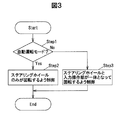
- FIG. 3 is a flowchart illustrating the operation of the steering control device according to the embodiment.
- the steering control device includes a steering wheel that enables adjustment of the traveling direction of the vehicle by a rotation operation performed, an input operation unit that is disposed in a central region of the steering wheel and receives an input operation by an operator, A switching unit that is connected to the steering wheel and the input operation unit and switches between rotation of the steering wheel and the input operation unit integrally or rotation of only the steering wheel, and an automatic operation mode for controlling the rotation of the steering wheel. And a control unit that controls the switching unit so that only the steering wheel rotates based on an input signal indicating the start.
- the steering control device of the embodiment only the steering wheel rotates in the automatic driving mode. Therefore, the steering control device is input even in the automatic driving mode as compared with the conventional device in which the steering wheel and the input operation unit rotate together. The operability of the operation unit is good.
- FIG. 1A is an explanatory diagram illustrating a steering control device according to an embodiment
- FIG. 1B is a block diagram of a vehicle control system including the steering control device and the steering control device
- FIG. 2A is an explanatory diagram illustrating an example of a rotational operation of the steering wheel in the manual operation mode of the steering control device according to the embodiment
- FIG. 2B is an explanatory diagram illustrating an exemplary rotational operation of the steering wheel in the automatic operation mode.
- the ratio between figures may be different from the actual ratio.
- main signals and information flows are indicated by arrows.
- the steering control device 1 switches to rotation of only the steering wheel 10 or rotation in which the steering wheel 10 and the input operation unit 12 are integrated depending on whether the operation mode of the vehicle 9 is the manual operation mode or the automatic operation mode. It is configured.
- the steering control device 1 is arranged in a steering wheel 10 that enables adjustment of the traveling direction of the vehicle 9 by a rotation operation performed, and a central region of the steering wheel 10.
- the input operation unit 12 that receives an input operation by the operator, the steering wheel 10 and the input operation unit 12 are connected to each other, and the steering wheel 10 and the input operation unit 12 are integrated, and only the steering wheel 10 is rotated.
- the switching unit 14 so that only the steering wheel 10 rotates based on the input of the input signal (mode signal S 1 ) indicating the start of the automatic driving mode for controlling the rotation of the steering wheel 10.
- a control unit 16 for controlling.
- the manual operation mode is a mode in which the operator operates the steering wheel 10, for example.
- the automatic driving mode is a mode in which, for example, the speed, brake, traveling direction, and the like of the vehicle 9 are controlled to the destination without being operated by the operator.
- the steering wheel 10 rotates clockwise and counterclockwise, for example, by driving of the driving unit 92.
- the vehicle control system 90 illustrated in FIG. 1B is a system that controls the traveling direction of the vehicle 9 in the automatic operation mode.
- the steering wheel 10 has a ring shape.
- the steering wheel 10 is a steering device for the vehicle 9 and is configured to change the direction of the wheels of the vehicle 9 via a steering shaft or the like.
- the input operation unit 12 includes a touch pad 121 that detects a touch operation performed on the operation surface 122, and a switch 125 that is disposed around the touch pad 121.
- the input operation unit 12 includes a plurality of switches 125 such that an operation surface 122 of the touch pad 121 is located at the center of a rectangular main body 120 and faces the operation surface 122. positioned.
- the touch pad 121 can operate an electronic device that is electromagnetically connected, for example.
- the touch pad 121 gives instructions such as movement and selection of the cursor displayed on the display unit of the electronic device, selection of the displayed icon, determination, dragging, and dropping by an operation with a conductive pen or finger, for example. It is configured to be able to. In the present embodiment, an operation with a finger (operation finger) will be described.
- this touch pad 121 for example, a touch pad of a resistance film method, an infrared method, a SAW (Surface Acoustic Wave) method, a capacitance method, or the like can be used. In this embodiment, a capacitive touch pad is used.
- the touch pad 121 rotates following the steering wheel 10 as shown in FIG. 2A.
- the operator grips and operates the steering wheel 10 it is easier for the operator to operate the touch pad 121 following the rotation of the steering wheel 10.
- the touch pad 121 when the driving mode of the vehicle 9 is the automatic driving mode, the touch pad 121 does not follow the steering wheel 10 and is stationary with respect to the vehicle 9 as shown in FIG. 2B. The rest of the touch pad 121 during the automatic operation mode facilitates the operation of the operation surface 122 by the operator.
- the switch 125 is disposed at a position where the operator can easily operate by gripping the steering wheel 10.
- two each are arranged so as to face each other with the operation surface 122 interposed therebetween.
- the switch 125 is a push switch.
- the switch 125 is stationary without following the steering wheel 10 when the vehicle 9 is in the automatic driving mode.
- the switch 125 rotates following the steering wheel 10 when the vehicle 9 is in the manual operation mode.
- the input operation unit 12 generates input information S 3 based on an operation performed on the touch pad 121 and the switch 125 and outputs the input information S 3 to the control unit 16.
- the switching unit 14 is configured to transmit the driving force from the driving unit 92 to the steering wheel 10. Further, as described above, the switching unit 14 can rotate only the steering wheel 10 when the vehicle 9 is in the automatic driving mode, and the steering wheel 10 and the input operation unit 12 are integrated when the vehicle 9 is in the manual driving mode. It is configured to be able to rotate.
- the switching unit 14 connects the steering wheel 10 and the input operation unit 12, thereby integrating the steering wheel 10 and the input operation unit 12, and switches to rotation of the steering wheel 10 only by releasing this connection.
- the input operation part 12 shall be fixed to the initial position by the switch part 14 so that it may stand still with respect to the vehicle 9, when a connection is cancelled
- This initial position is, for example, a position where the input operation unit 12 is not rotating as shown in FIG. 1A.
- Switching unit 14 switches the connection based on the switching signal S 2 output from the control unit 16.
- the switching signal S 2 is a signal control unit 16 is generated based on the mode signals S 1 to be input.
- the control unit 16 includes, for example, a CPU (Central Processing Unit) that performs operations and processes on acquired data according to a stored program, a RAM (Random Access Memory) that is a semiconductor memory, a ROM (Read Only Memory), and the like. Microcomputer. In this ROM, for example, a program for operating the control unit 16 is stored. For example, the RAM is used as a storage area for temporarily storing calculation results and the like.
- a CPU Central Processing Unit
- RAM Random Access Memory
- ROM Read Only Memory
- Control unit 16 the operator switch 14 to the steering wheel 10 and the input operation unit 12 is rotated together on the basis of the input of the mode signals S 1 indicating release of the automatic operation mode to operate the steering wheel 10 Is configured to control.
- the control unit 16 when the input mode signal S 1 indicates the manual operation mode, the control unit 16 generates a switching signal S 2 that rotates the steering wheel 10 and the input operation unit 12 together and outputs the switching signal S 2 to the switching unit 14.
- the control unit 16 when the mode signal S 1 indicating the automatic driving mode is input, the control unit 16 generates and outputs a switching signal S 2 for preventing the input operation unit 12 from following the rotation of the steering wheel 10, and outputs the switching signal S 2. 14 is controlled.
- the driving unit 92 and the steering wheel 10 are connected.
- the driving assistance includes, for example, assistance for preventing spin on a rough road such as a snowy road, assistance for lane keeping, assistance for generating an appropriate operational feeling, and the like.
- the input operation unit 12 may be configured to be directly driven by the drive unit 92, or may be configured to rotate together with the steering wheel 10 by being integrated with the steering wheel 10. In the present embodiment, as an example, it is assumed that the steering wheel 10 and the input operation unit 12 are integrally controlled as driving assistance in the manual driving mode.
- control unit 16 is configured to generate the operation information S 4 based on the input information S 3 output from the input operation unit 12 and output the operation information S 4 to the vehicle control unit 900.
- the vehicle control system 90 includes a steering control device 1, a drive unit 92, a vehicle information generation unit 94, and an automatic driving control unit 96, as shown in FIG. 1B.
- the drive unit 92 is configured to drive the steering wheel 10 via the switching unit 14.
- the drive unit 92 includes a motor and the like.
- the drive unit 92 may generate a reaction force by driving in the direction opposite to the rotation direction of the steering wheel 10 as driving assistance in the manual operation mode.
- Drive unit 92 is controlled by a drive signal S 5 output from the automatic driving control section 96.
- Automatic driving control section 96 generates a drive signal S 5 based on the vehicle information S 6 output from the vehicle information generating unit 94.
- Vehicle information generating unit 94 as an example, the speed information of the vehicle 9, position information, map information, road information, obtains information about the vehicle 9, such as route information to the destination to generate vehicle information S 6 It is configured.
- the vehicle information generation part 94 acquires the information regarding the vehicle 9 via the vehicle control part 900 of the vehicle 9, as an example.
- the vehicle control unit 900 is an ECU (Electronic Control Unit) that comprehensively controls sensors and electronic devices mounted on the vehicle 9.
- the automatic operation control unit 96 is a microcomputer including a CPU, a RAM, a ROM, and the like.
- the automatic driving control unit 96 generates and outputs a mode signal S 1 based on the instruction signal S 7 output from the vehicle control unit 900.
- the instruction signal S 7 is, for example, a signal indicating that shifts to manual operation mode or the automatic operation mode.
- the automatic operation control unit 96 When the instruction signal S 7 is a signal indicating the manual operation mode, the automatic operation control unit 96 generates a mode signal S 1 indicating the manual operation mode and outputs it to the control unit 16.
- the automatic driving control section 96 when the instruction signal S 7 is a signal indicating the automatic operation mode, and outputs to generate a mode signals S 1 indicating the automatic operation mode to the control unit 16, generates a drive signal S 5 Then, the drive unit 92 is controlled.
- the automatic operation mode and the manual operation mode are selected by the operation of the mode switch by the operator.
- the vehicle control unit 900 generates the instruction signal S 7 based on the operation of the mode switch and outputs the instruction signal S 7 to the automatic driving control unit 96.
- Control unit 16 determines whether the operation mode is the manual operation mode or the automatic operation mode of the vehicle 9 based on the mode signals S 1 to be input after the power supply of the vehicle 9 is turned on. Control unit 16, when the operation mode of the vehicle 9 is an automatic operation mode (Step1: Yes), only the steering wheel 10 and outputs a switching signal S 2 corresponding to the determination result is driven by the drive unit 92 rotates The switching unit 14 is controlled so as to be performed (Step 2). For example, as shown in FIG. 2B, the steering wheel 10 does not rotate integrally with the input operation unit 12 by driving the drive unit 92 but rotates alone.
- the control unit 16 when the operation mode of the vehicle 9 is a manual operation mode (Step1: No), the input operation unit 12 and the steering wheel 10 and outputs a switching signal S 2 corresponding to the determination result together Then, the switching unit 14 is controlled so as to rotate (Step 3). For example, as shown in FIG. 2A, the steering wheel 10 rotates integrally with the input operation unit 12 according to the operation of the operator.
- the steering control device 1 has good operability of the input operation unit 12 even in the automatic driving mode. Specifically, in the manual operation mode, since the operator holds the steering wheel 10, it is easy to operate the input operation unit 12 that rotates together with the steering wheel 10. However, when the steering wheel 10 and the input operation unit 12 are rotated together in the automatic operation mode, the operator must operate the rotating input operation unit 12 and the input operation unit is stationary with respect to itself. The operability is not good compared to the case of operating No. 12. As an example, in the automatic driving mode, when the operator operates the input operation unit 12 to instruct overtaking or the like, the operability is better when the input operation unit 12 does not rotate.
- the steering wheel 10 and the input operation unit 12 are integrated in the manual operation mode, and only the steering wheel 10 rotates in the automatic operation mode. Therefore, the operation of the touch pad 121 and the switch 125 of the input operation unit 12 is always performed. Good sex.
- the input operation unit 12 does not rotate with the steering wheel 10 in the automatic operation mode, and the input operation unit 12 and the steering wheel 10 rotate integrally in the manual operation mode.
- the operability is always good, so that the operator's fingers and arms are prevented from being sandwiched between the steering wheel 10 and the input operation unit 12.
- the design control is less restricted and the degree of freedom of the design is higher than when using a configuration that avoids them. .
Landscapes
- Engineering & Computer Science (AREA)
- Chemical & Material Sciences (AREA)
- Combustion & Propulsion (AREA)
- Transportation (AREA)
- Mechanical Engineering (AREA)
- Steering Controls (AREA)
- Steering Control In Accordance With Driving Conditions (AREA)
Abstract
ステアリング制御装置1は、なされた回転操作によって車両9の進行方向の調整を可能とするステアリングホイール10と、ステアリングホイール10の中央の領域に配置され、操作者による入力操作を受け付ける入力操作部12と、ステアリングホイール10と入力操作部12とに接続され、ステアリングホイール10と入力操作部12が一体となった回転、及びステアリングホイール10のみの回転のいずれかに切り替える切替部14と、ステアリングホイール10の回転を制御する自動運転モードの開始を示すモード信号S1の入力に基づいてステアリングホイール10のみが回転するように切替部14を制御する制御部16と、を備えている。
Description
本発明は、ステアリング制御装置に関する。
ステアリングホイールのセンターパッドに配置されたディスプレイと、ディスプレイ上に配置されたタッチパネルと、を備えた車載システムが知られている(例えば、特許文献1参照。)。
特許文献1に開示されたディスプレイは、ステアリングホイールのセンターパッド内に配置されている。またタッチパネルは、ディスプレイの表示面上に配置されている。このディスプレイとタッチパネルは、ステアリングホイールと共に回転する。
特許文献1に開示された車載システムは、例えば、車両が周辺の状況に応じてステアリングホイールを自動的に制御して車両の進路を変更する自動運転モードが動作する場合、ステアリングホイールの回転と共に一体的に、ステアリングホイールの中央の領域に配置されたて入力操作を受け付ける入力操作部(タッチパネル等)も回転するので操作性が良くなかった。
本発明の目的は、自動運転モードであっても、入力操作部の操作性が良いステアリング制御装置を提供することにある。
本発明の一態様によるステアリング制御装置は、なされた回転操作によって車両の進行方向の調整を可能とするステアリングホイールと、ステアリングホイールの中央の領域に配置され、操作者による入力操作を受け付ける入力操作部と、ステアリングホイールと入力操作部とに接続され、ステアリングホイールと入力操作部が一体となった回転、及びステアリングホイールのみの回転のいずれかに切り替える切替部と、ステアリングホイールの回転を制御する自動運転モードの開始を示す入力信号の入力に基づいてステアリングホイールのみが回転するように切替部を制御する制御部と、を備える。
本発明の一実施態様によれば、自動運転モードであっても入力操作部の操作性が良いステアリング制御装置を提供することができる。
(実施形態の要約)
実施形態に係るステアリング制御装置は、なされた回転操作によって車両の進行方向の調整を可能とするステアリングホイールと、ステアリングホイールの中央の領域に配置され、操作者による入力操作を受け付ける入力操作部と、ステアリングホイールと入力操作部とに接続され、ステアリングホイールと入力操作部が一体となった回転、及びステアリングホイールのみの回転のいずれかに切り替える切替部と、ステアリングホイールの回転を制御する自動運転モードの開始を示す入力信号の入力に基づいてステアリングホイールのみが回転するように切替部を制御する制御部と、を備えている。
実施形態に係るステアリング制御装置は、なされた回転操作によって車両の進行方向の調整を可能とするステアリングホイールと、ステアリングホイールの中央の領域に配置され、操作者による入力操作を受け付ける入力操作部と、ステアリングホイールと入力操作部とに接続され、ステアリングホイールと入力操作部が一体となった回転、及びステアリングホイールのみの回転のいずれかに切り替える切替部と、ステアリングホイールの回転を制御する自動運転モードの開始を示す入力信号の入力に基づいてステアリングホイールのみが回転するように切替部を制御する制御部と、を備えている。
実施形態のステアリング制御装置は、自動運転モードの際、ステアリングホイールのみが回転するので、ステアリングホイールと入力操作部とが一体となって回転する従来装置と比べて、自動運転モードであっても入力操作部の操作性が良い。
[実施形態]
(ステアリング制御装置1の概要)
図1Aは、実施形態に係るステアリング制御装置を示す説明図であり、図1Bは、ステアリング制御装置とステアリング制御装置を含む車両制御システムのブロック図である。図2Aは、実施形態に係るステアリング制御装置の手動運転モードにおけるステアリングホイールの回転動作例を示す説明図であり、図2Bは、自動運転モードにおけるステアリングホイールの回転動作例を示す説明図である。なお、以下に記載する実施形態に係る各図において、図形間の比率は、実際の比率とは異なる場合がある。また図1Bでは、主な信号や情報の流れを矢印で示している。
(ステアリング制御装置1の概要)
図1Aは、実施形態に係るステアリング制御装置を示す説明図であり、図1Bは、ステアリング制御装置とステアリング制御装置を含む車両制御システムのブロック図である。図2Aは、実施形態に係るステアリング制御装置の手動運転モードにおけるステアリングホイールの回転動作例を示す説明図であり、図2Bは、自動運転モードにおけるステアリングホイールの回転動作例を示す説明図である。なお、以下に記載する実施形態に係る各図において、図形間の比率は、実際の比率とは異なる場合がある。また図1Bでは、主な信号や情報の流れを矢印で示している。
ステアリング制御装置1は、例えば、車両9の運転モードが手動運転モードか自動運転モードかによって、ステアリングホイール10のみの回転、又はステアリングホイール10と入力操作部12が一体となった回転に切り替わるように構成されている。
具体的には、ステアリング制御装置1は、図1A及び1Bに示すように、なされた回転操作によって車両9の進行方向の調整を可能とするステアリングホイール10と、ステアリングホイール10の中央の領域に配置され、操作者による入力操作を受け付ける入力操作部12と、ステアリングホイール10と入力操作部12とに接続され、ステアリングホイール10と入力操作部12が一体となった回転、及びステアリングホイール10のみの回転のいずれかに切り替える切替部14と、ステアリングホイール10の回転を制御する自動運転モードの開始を示す入力信号(モード信号S1)の入力に基づいてステアリングホイール10のみが回転するように切替部14を制御する制御部16と、を備えている。
手動運転モードとは、例えば、操作者がステアリングホイール10を操作するモードである。また自動運転モードとは、例えば、操作者が操作することなく、車両9の速度、ブレーキ、進行方向などを制御して目的地まで制御するモードである。この自動運転モードにおいてステアリングホイール10は、例えば、駆動部92の駆動によって時計回り及び反時計回りに回転する。図1Bに示す車両制御システム90は、一例として、自動運転モードにおける車両9の進行方向を制御するシステムであるものとする。
(ステアリングホイール10の構成)
ステアリングホイール10は、図1Aに示すように、リング形状を有している。このステアリングホイール10は、車両9の操舵装置であり、ステアリングシャフトなどを介して車両9の車輪の向きを変えるように構成されている。
ステアリングホイール10は、図1Aに示すように、リング形状を有している。このステアリングホイール10は、車両9の操舵装置であり、ステアリングシャフトなどを介して車両9の車輪の向きを変えるように構成されている。
(入力操作部12の構成)
入力操作部12は、例えば、図1Aに示すように、操作面122になされたタッチ操作を検出するタッチパッド121と、タッチパッド121の周囲に配置されたスイッチ125と、を備えている。
入力操作部12は、例えば、図1Aに示すように、操作面122になされたタッチ操作を検出するタッチパッド121と、タッチパッド121の周囲に配置されたスイッチ125と、を備えている。
入力操作部12は、例えば、図1Aに示すように、矩形状を有する本体120の中央にタッチパッド121の操作面122が位置し、操作面122を挟んで対向するように複数のスイッチ125が位置している。
タッチパッド121は、例えば、電磁気的に接続された電子機器の操作を行うことが可能である。タッチパッド121は、例えば、導電性を有するペンや指による操作により、電子機器の表示部に表示されたカーソルの移動や選択、表示されたアイコンの選択、決定、ドラッグ、ドロップなどの指示を行うことができるように構成されている。本実施形態では、指(操作指)による操作について説明する。
このタッチパッド121は、例えば、抵抗膜方式、赤外線方式、SAW(Surface Acoustic Wave)方式、静電容量方式などのタッチパッドを用いることが可能である。本実施形態では、静電容量方式のタッチパッドを用いるものとする。
タッチパッド121は、車両9の運転モードが手動運転モードである場合、図2Aに示すように、ステアリングホイール10に追従して回転する。操作者は、ステアリングホイール10を把持して操作している際に、タッチパッド121がステアリングホイール10の回転に追従している方が操作がし易い。
これに対し、タッチパッド121は、車両9の運転モードが自動運転モードである場合、図2Bに示すように、ステアリングホイール10に追従せずに車両9に対して静止している。この自動運転モードの際のタッチパッド121の静止は、操作者による操作面122の操作を容易にしている。
スイッチ125は、操作者がステアリングホイール10を把持して操作し易い位置に配置されている。本実施形態では、一例として、図1Aに示すように、操作面122を挟んで対向するように二つずつ配置されている。このスイッチ125は、一例として、プッシュスイッチである。
スイッチ125は、タッチパッド121と同様に、車両9が自動運転モードにある場合、ステアリングホイール10に追従せずに静止している。またスイッチ125は、車両9が手動運転モードにある場合、ステアリングホイール10に追従して回転する。
入力操作部12は、タッチパッド121及びスイッチ125になされた操作に基づいて入力情報S3を生成して制御部16に出力する。
(切替部14の構成)
切替部14は、駆動部92による駆動力をステアリングホイール10に伝達するように構成されている。また切替部14は、上述のように、車両9が自動運転モードにある場合、ステアリングホイール10のみを回転可能とし、手動運転モードにある場合、ステアリングホイール10と入力操作部12を一体となった回転が可能となるように構成されている。
切替部14は、駆動部92による駆動力をステアリングホイール10に伝達するように構成されている。また切替部14は、上述のように、車両9が自動運転モードにある場合、ステアリングホイール10のみを回転可能とし、手動運転モードにある場合、ステアリングホイール10と入力操作部12を一体となった回転が可能となるように構成されている。
つまり切替部14は、ステアリングホイール10と入力操作部12を接続することにより、ステアリングホイール10と入力操作部12とを一体とし、この接続を解除することにより、ステアリングホイール10のみの回転に切り替える。なお入力操作部12は、接続が解除された場合、車両9に対して静止するように、切替部14によって初期位置に固定されるものとする。この初期位置は、例えば、図1Aに示すように、入力操作部12が回転していない位置である。
切替部14は、制御部16から出力される切替信号S2に基づいて接続の切替を行う。この切替信号S2は、入力するモード信号S1に基づいて制御部16が生成する信号である。
(制御部16の構成)
制御部16は、例えば、記憶されたプログラムに従って、取得したデータに演算、加工などを行うCPU(Central Processing Unit)、半導体メモリであるRAM(Random Access Memory)及びROM(Read Only Memory)などから構成されるマイクロコンピュータである。このROMには、例えば、制御部16が動作するためのプログラムが格納されている。RAMは、例えば、一時的に演算結果などを格納する記憶領域として用いられる。
制御部16は、例えば、記憶されたプログラムに従って、取得したデータに演算、加工などを行うCPU(Central Processing Unit)、半導体メモリであるRAM(Random Access Memory)及びROM(Read Only Memory)などから構成されるマイクロコンピュータである。このROMには、例えば、制御部16が動作するためのプログラムが格納されている。RAMは、例えば、一時的に演算結果などを格納する記憶領域として用いられる。
制御部16は、操作者がステアリングホイール10を操作する自動運転モードの解除を示すモード信号S1の入力に基づいてステアリングホイール10と入力操作部12が一体となって回転するように切替部14を制御するように構成されている。
つまり制御部16は、入力したモード信号S1が手動運転モードを示している場合、ステアリングホイール10と入力操作部12を一体に回転させる切替信号S2を生成して切替部14に出力する。切替部14は、入力した切替信号S2に基づいてステアリングホイール10及び入力操作部12が一体となって回転するように切り替える。
また制御部16は、自動運転モードを示すモード信号S1が入力すると、ステアリングホイール10の回転に入力操作部12が追従しないようにするための切替信号S2を生成して出力し、切替部14を制御する。
なお車両9が手動運転モードにおいて操作者の運転補助としてステアリングホイール10の回転を制御する場合、駆動部92とステアリングホイール10は、接続される。この運転補助は、一例として、雪道などの悪路におけるスピン防止のための補助、レーンキープのための補助、適切な操作感を生成するための補助などである。この場合、入力操作部12が直接駆動部92に駆動されるように構成されても良いし、ステアリングホイール10と一体となることでステアリングホイール10と共に回転するように構成されても良い。本実施形態では、一例として、手動運転モードにおいてステアリングホイール10と入力操作部12が一体となって運転補助として制御されるものとする。
制御部16は、例えば、入力操作部12から出力された入力情報S3に基づいて操作情報S4を生成し、車両制御部900に出力するように構成されている。
(車両制御システム90の構成)
車両制御システム90は、一例として、図1Bに示すように、ステアリング制御装置1と、駆動部92と、車両情報生成部94と、自動運転制御部96と、を備えている。
車両制御システム90は、一例として、図1Bに示すように、ステアリング制御装置1と、駆動部92と、車両情報生成部94と、自動運転制御部96と、を備えている。
駆動部92は、切替部14を介してステアリングホイール10を駆動するように構成されている。この駆動部92は、一例として、モータなどを含んで構成されている。なお駆動部92は、上述のように、手動運転モードの際、運転補助としてステアリングホイール10の回転方向と反対方向の駆動による反力の生成などを行っても良い。
駆動部92は、自動運転制御部96から出力される駆動信号S5によって制御される。自動運転制御部96は、車両情報生成部94から出力された車両情報S6に基づいて駆動信号S5を生成する。
車両情報生成部94は、一例として、車両9の速度情報、位置情報、地図情報、道路情報、目的地までの経路情報などの車両9に関する情報を取得して車両情報S6を生成するように構成されている。車両情報生成部94は、一例として、車両9の車両制御部900を介して車両9に関する情報を取得する。この車両制御部900は、車両9に搭載されたセンサや電子機器などを総合的に制御するECU(Electronic Control Unit)である。
自動運転制御部96は、一例として、CPU、RAM及びROMなどから構成されるマイクロコンピュータである。この自動運転制御部96は、例えば、車両制御部900から出力された指示信号S7に基づいてモード信号S1を生成して出力する。
この指示信号S7は、例えば、手動運転モード又は自動運転モードに移行することを示す信号である。自動運転制御部96は、指示信号S7が手動運転モードを示す信号である場合、手動運転モードを示すモード信号S1を生成して制御部16に出力する。
また自動運転制御部96は、指示信号S7が自動運転モードを示す信号である場合、自動運転モードを示すモード信号S1を生成して制御部16に出力すると共に、駆動信号S5を生成して駆動部92を制御する。
自動運転モード及び手動運転モードは、一例として、操作者によるモードスイッチの操作によって選択される。車両制御部900は、例えば、モードスイッチの操作に基づいて指示信号S7を生成し、自動運転制御部96に出力する。
以下にステアリング制御装置1の動作について図3のフローチャートに従って説明する。
(動作)
制御部16は、車両9の電源が投入された後に入力するモード信号S1に基づいて車両9の運転モードが手動運転モードか自動運転モードかを判定する。制御部16は、車両9の運転モードが自動運転モードであった場合(Step1:Yes)、判定結果に対応する切替信号S2を出力してステアリングホイール10のみが駆動部92によって駆動されて回転するように切替部14を制御する(Step2)。ステアリングホイール10は、例えば、図2Bに示すように、駆動部92の駆動によって入力操作部12と一体に回転せず、単体で回転する。
制御部16は、車両9の電源が投入された後に入力するモード信号S1に基づいて車両9の運転モードが手動運転モードか自動運転モードかを判定する。制御部16は、車両9の運転モードが自動運転モードであった場合(Step1:Yes)、判定結果に対応する切替信号S2を出力してステアリングホイール10のみが駆動部92によって駆動されて回転するように切替部14を制御する(Step2)。ステアリングホイール10は、例えば、図2Bに示すように、駆動部92の駆動によって入力操作部12と一体に回転せず、単体で回転する。
また制御部16は、車両9の運転モードが手動運転モードであった場合(Step1:No)、判定結果に対応する切替信号S2を出力してステアリングホイール10と入力操作部12が一体となって回転するように切替部14を制御する(Step3)。ステアリングホイール10は、例えば、図2Aに示すように、操作者の操作に従って入力操作部12と一体に回転する。
(実施形態の効果)
本実施形態に係るステアリング制御装置1は、自動運転モードであっても入力操作部12の操作性が良い。具体的には、手動運転モードでは、操作者は、ステアリングホイール10を把持しているので、ステアリングホイール10と共に回転する入力操作部12を操作し易い。しかし自動運転モードにおいてステアリングホイール10と入力操作部12とが一体となって回転した場合、操作者は、回転する入力操作部12を操作しなければならず、自身に対して静止する入力操作部12を操作する場合と比べて操作性が良くない。一例として、自動運転モードにおいて、操作者が入力操作部12を操作して追い越しなどを指示する場合、入力操作部12が回転しない方が、操作性が良い。従ってステアリング制御装置1は、手動運転モードではステアリングホイール10と入力操作部12が一体となり、自動運転モードではステアリングホイール10のみが回転するので、常に入力操作部12のタッチパッド121及びスイッチ125の操作性が良い。
本実施形態に係るステアリング制御装置1は、自動運転モードであっても入力操作部12の操作性が良い。具体的には、手動運転モードでは、操作者は、ステアリングホイール10を把持しているので、ステアリングホイール10と共に回転する入力操作部12を操作し易い。しかし自動運転モードにおいてステアリングホイール10と入力操作部12とが一体となって回転した場合、操作者は、回転する入力操作部12を操作しなければならず、自身に対して静止する入力操作部12を操作する場合と比べて操作性が良くない。一例として、自動運転モードにおいて、操作者が入力操作部12を操作して追い越しなどを指示する場合、入力操作部12が回転しない方が、操作性が良い。従ってステアリング制御装置1は、手動運転モードではステアリングホイール10と入力操作部12が一体となり、自動運転モードではステアリングホイール10のみが回転するので、常に入力操作部12のタッチパッド121及びスイッチ125の操作性が良い。
ステアリング制御装置1は、自動運転モードでは入力操作部12がステアリングホイール10と共に回転せず、手動運転モードでは入力操作部12とステアリングホイール10が一体となって回転するので、運転モードによらず入力操作部が回転しないように構成された従来装置と比べて、常に操作性が良いので、操作者の指や腕をステアリングホイール10と入力操作部12の間に挟むようなことが抑制される。
ステアリング制御装置1は、操作性が良く、また指や腕を挟むようなことが抑制されるので、それらを回避する構成を用いる場合と比べて、意匠の制約が少なくて意匠の自由度が高い。
以上、本発明のいくつかの実施形態を説明したが、これらの実施形態は、一例に過ぎず、特許請求の範囲に係る発明を限定するものではない。これら新規な実施形態は、その他の様々な形態で実施されることが可能であり、本発明の要旨を逸脱しない範囲で、種々の省略、置き換え、変更などを行うことができる。また、これら実施形態の中で説明した特徴の組合せの全てが発明の課題を解決するための手段に必須であるとは限らない。さらに、これら実施形態は、発明の範囲及び要旨に含まれると共に、特許請求の範囲に記載された発明とその均等の範囲に含まれる。
1 ステアリング制御装置
9 車両
10 ステアリングホイール
12 入力操作部
14 切替部
16 制御部
90 車両制御システム
92 駆動部
94 車両情報生成部
96 自動運転制御部
120 本体
121 タッチパッド
122 操作面
125 スイッチ
900 車両制御部
9 車両
10 ステアリングホイール
12 入力操作部
14 切替部
16 制御部
90 車両制御システム
92 駆動部
94 車両情報生成部
96 自動運転制御部
120 本体
121 タッチパッド
122 操作面
125 スイッチ
900 車両制御部
Claims (5)
- なされた回転操作によって車両の進行方向の調整を可能とするステアリングホイールと、
前記ステアリングホイールの中央の領域に配置され、操作者による入力操作を受け付ける入力操作部と、
前記ステアリングホイールと前記入力操作部とに接続され、前記ステアリングホイールと前記入力操作部が一体となった回転、及び前記ステアリングホイールのみの回転のいずれかに切り替える切替部と、
前記ステアリングホイールの回転を制御する自動運転モードの開始を示す入力信号の入力に基づいて前記ステアリングホイールのみが回転するように前記切替部を制御する制御部と、を備えたステアリング制御装置。 - 前記制御部は、前記自動運転モードの解除を示す入力信号の入力に基づいて前記ステアリングホイールと前記入力操作部が一体となって回転するように前記切替部を制御する、請求項1に記載のステアリング制御装置。
- 前記入力操作部は、操作面になされたタッチ操作を検出するタッチパッドと、前記タッチパッドの周囲に配置されたスイッチと、を有する、請求項1又は2に記載のステアリング制御装置。
- 前記切替部は、手動運転モードにおいて、前記ステアリングホイールと前記入力操作部との接続により前記ステアリングホイールと前記入力操作部が一体となった前記回転を許容し、前記自動運転モードにおいて、前記ステアリングホイールと前記入力操作部との前記接続を解除することにより前記ステアリングホイールのみの前記回転を許容する、請求項1~3の何れか1項に記載のステアリング制御装置。
- 前記切替部は、前記自動運転モードにおいて、駆動部による駆動力を前記ステアリングホイールに伝達する、請求項1~4の何れか1項に記載のステアリング制御装置。
Priority Applications (2)
| Application Number | Priority Date | Filing Date | Title |
|---|---|---|---|
| CN201780004976.8A CN108367769B (zh) | 2016-01-27 | 2017-01-18 | 转向控制装置 |
| US16/065,473 US10464589B2 (en) | 2016-01-27 | 2017-01-18 | Steering control device |
Applications Claiming Priority (2)
| Application Number | Priority Date | Filing Date | Title |
|---|---|---|---|
| JP2016-013448 | 2016-01-27 | ||
| JP2016013448A JP6579579B2 (ja) | 2016-01-27 | 2016-01-27 | ステアリング制御装置 |
Publications (1)
| Publication Number | Publication Date |
|---|---|
| WO2017130815A1 true WO2017130815A1 (ja) | 2017-08-03 |
Family
ID=59397784
Family Applications (1)
| Application Number | Title | Priority Date | Filing Date |
|---|---|---|---|
| PCT/JP2017/001553 Ceased WO2017130815A1 (ja) | 2016-01-27 | 2017-01-18 | ステアリング制御装置 |
Country Status (4)
| Country | Link |
|---|---|
| US (1) | US10464589B2 (ja) |
| JP (1) | JP6579579B2 (ja) |
| CN (1) | CN108367769B (ja) |
| WO (1) | WO2017130815A1 (ja) |
Cited By (1)
| Publication number | Priority date | Publication date | Assignee | Title |
|---|---|---|---|---|
| US11110798B2 (en) | 2019-01-31 | 2021-09-07 | Toyota Motor Engineering & Manufacturing North America, Inc. | Multi-function vehicle input apparatuses with operational buttons for vehicle systems control and methods incorporating the same |
Families Citing this family (7)
| Publication number | Priority date | Publication date | Assignee | Title |
|---|---|---|---|---|
| US10583855B2 (en) * | 2017-09-05 | 2020-03-10 | Byton Gmbh | Steering device for a vehicle, in particular an electric vehicle |
| JP7197674B2 (ja) * | 2019-02-27 | 2022-12-27 | 本田技研工業株式会社 | 操舵操作子 |
| CN110341721A (zh) * | 2019-06-24 | 2019-10-18 | 江苏大学 | 一种自动驾驶模式切换为人工驾驶模式的控制系统及方法 |
| KR102910412B1 (ko) * | 2020-02-06 | 2026-01-13 | 현대모비스 주식회사 | 주행모드 전환 장치 및 그 방법 |
| USD931167S1 (en) * | 2020-02-14 | 2021-09-21 | Lg Electronics Inc. | Steering wheel for automobile |
| CN111923994B (zh) * | 2020-08-28 | 2025-05-27 | 浦立泽智能科技(昆山)有限公司 | 一种方向盘 |
| CN114475768A (zh) * | 2020-10-28 | 2022-05-13 | 西安合众思壮导航技术有限公司 | 自动驾驶系统、方法及电动方向盘 |
Citations (4)
| Publication number | Priority date | Publication date | Assignee | Title |
|---|---|---|---|---|
| JPS59102555U (ja) * | 1982-12-28 | 1984-07-10 | 株式会社東海理化電機製作所 | ステアリングスイツチパツド |
| JPS6058566U (ja) * | 1983-09-30 | 1985-04-23 | 株式会社東海理化電機製作所 | ステアリングスイツチパツド |
| DE10117824A1 (de) * | 2001-04-10 | 2002-10-17 | Daimler Chrysler Ag | Lenkrad eines Kraftfahrzeugs mit integrierten Bedienelementen |
| EP1323618A1 (fr) * | 2001-12-20 | 2003-07-02 | Peugeot Citroen Automobiles | Ensemble de direction de véhicule |
Family Cites Families (11)
| Publication number | Priority date | Publication date | Assignee | Title |
|---|---|---|---|---|
| JP2001322516A (ja) * | 2000-05-17 | 2001-11-20 | Misawa Homes Co Ltd | 自動車用キー入力装置 |
| WO2006133260A2 (en) * | 2005-06-06 | 2006-12-14 | Joneso Design And Consulting, Inc. | Vehicle information/control system |
| GB2471892B (en) * | 2009-07-17 | 2016-03-02 | Gm Global Tech Operations Inc | Switch assembly comprising a steering wheel |
| JP2013025620A (ja) | 2011-07-22 | 2013-02-04 | Alpine Electronics Inc | 車載システム |
| JP5843283B2 (ja) * | 2011-11-07 | 2016-01-13 | アルプス電気株式会社 | 車両用入力装置 |
| ITVR20110208A1 (it) * | 2011-11-24 | 2013-05-25 | Gussi Italia S R L | Dispositivo di sterzo per veicoli |
| WO2014058087A1 (en) * | 2012-10-11 | 2014-04-17 | Lg Electronics Inc. | Display device mounted on steering wheel of vehicle and control method thereof |
| AU2013352456B2 (en) * | 2012-11-27 | 2015-11-26 | Neonode Inc. | Light-based touch controls on a steering wheel and dashboard |
| US9067618B2 (en) * | 2013-06-11 | 2015-06-30 | Honda Motor Co., Ltd. | Touch-based system for controlling an automotive steering wheel |
| FR3023519A1 (fr) * | 2014-12-09 | 2016-01-15 | Continental Automotive France | Systeme pour detecter la presence et la position de main et/ou de doigt sur un volant |
| US10160472B2 (en) * | 2015-10-20 | 2018-12-25 | Steering Solutions Ip Holding Corporation | Steering column with stationary hub |
-
2016
- 2016-01-27 JP JP2016013448A patent/JP6579579B2/ja active Active
-
2017
- 2017-01-18 CN CN201780004976.8A patent/CN108367769B/zh active Active
- 2017-01-18 US US16/065,473 patent/US10464589B2/en active Active
- 2017-01-18 WO PCT/JP2017/001553 patent/WO2017130815A1/ja not_active Ceased
Patent Citations (4)
| Publication number | Priority date | Publication date | Assignee | Title |
|---|---|---|---|---|
| JPS59102555U (ja) * | 1982-12-28 | 1984-07-10 | 株式会社東海理化電機製作所 | ステアリングスイツチパツド |
| JPS6058566U (ja) * | 1983-09-30 | 1985-04-23 | 株式会社東海理化電機製作所 | ステアリングスイツチパツド |
| DE10117824A1 (de) * | 2001-04-10 | 2002-10-17 | Daimler Chrysler Ag | Lenkrad eines Kraftfahrzeugs mit integrierten Bedienelementen |
| EP1323618A1 (fr) * | 2001-12-20 | 2003-07-02 | Peugeot Citroen Automobiles | Ensemble de direction de véhicule |
Cited By (1)
| Publication number | Priority date | Publication date | Assignee | Title |
|---|---|---|---|---|
| US11110798B2 (en) | 2019-01-31 | 2021-09-07 | Toyota Motor Engineering & Manufacturing North America, Inc. | Multi-function vehicle input apparatuses with operational buttons for vehicle systems control and methods incorporating the same |
Also Published As
| Publication number | Publication date |
|---|---|
| US10464589B2 (en) | 2019-11-05 |
| CN108367769B (zh) | 2020-07-28 |
| JP6579579B2 (ja) | 2019-09-25 |
| JP2017132345A (ja) | 2017-08-03 |
| US20180370556A1 (en) | 2018-12-27 |
| CN108367769A (zh) | 2018-08-03 |
Similar Documents
| Publication | Publication Date | Title |
|---|---|---|
| JP6579579B2 (ja) | ステアリング制御装置 | |
| US11999424B2 (en) | Rotation control system for a steering wheel and method | |
| CN107284512B (zh) | 用于自主车辆的转向系统 | |
| CN108698596B (zh) | 驾驶切换装置 | |
| CN107031699B (zh) | 用于方向盘的转动控制系统及方法 | |
| CN109641524B (zh) | 转向操纵角显示装置 | |
| CN109475079B (zh) | 触觉驾驶引导系统 | |
| CN106240623A (zh) | 可缩回方向盘手势控制 | |
| JP2020163907A5 (ja) | ||
| US10099723B2 (en) | Integrated clutch steering system | |
| JP4891286B2 (ja) | 遠隔操作装置 | |
| JPWO2015005026A1 (ja) | 車両用操舵制御装置および車両用操舵制御方法 | |
| JP2021175631A (ja) | 車両用ステアリング装置 | |
| JP2019104287A (ja) | 車両の遠隔操作システム | |
| WO2012005107A1 (ja) | 車両用操舵装置 | |
| JP2015033991A (ja) | インターフェースデバイス、インターフェースデバイス制御方法、及びインターフェースデバイス制御プログラム | |
| JP2017094964A (ja) | 車載システム及び情報処理装置 | |
| JP7212537B2 (ja) | 車両制御装置、車両及び車両制御方法 | |
| JP2021102372A (ja) | 車両、表示制御装置、及び表示制御方法 | |
| JP2013180717A (ja) | 車両用走行制御装置及び方法 | |
| JP2017095066A (ja) | 車両及び車両における制御方法 | |
| JP7192413B2 (ja) | 車両用操作装置 | |
| JP2024054494A (ja) | 処理装置 | |
| JP5949308B2 (ja) | 車両用方向指示装置 | |
| WO2017216869A1 (ja) | 車両用入力装置 |
Legal Events
| Date | Code | Title | Description |
|---|---|---|---|
| 121 | Ep: the epo has been informed by wipo that ep was designated in this application |
Ref document number: 17744045 Country of ref document: EP Kind code of ref document: A1 |
|
| NENP | Non-entry into the national phase |
Ref country code: DE |
|
| 122 | Ep: pct application non-entry in european phase |
Ref document number: 17744045 Country of ref document: EP Kind code of ref document: A1 |