WO2017130651A1 - ブーム変位装置及びブームスプレーヤ - Google Patents
ブーム変位装置及びブームスプレーヤ Download PDFInfo
- Publication number
- WO2017130651A1 WO2017130651A1 PCT/JP2017/000149 JP2017000149W WO2017130651A1 WO 2017130651 A1 WO2017130651 A1 WO 2017130651A1 JP 2017000149 W JP2017000149 W JP 2017000149W WO 2017130651 A1 WO2017130651 A1 WO 2017130651A1
- Authority
- WO
- WIPO (PCT)
- Prior art keywords
- boom
- hydraulic oil
- accumulator
- pressure
- state
- Prior art date
- Legal status (The legal status is an assumption and is not a legal conclusion. Google has not performed a legal analysis and makes no representation as to the accuracy of the status listed.)
- Ceased
Links
Images






Classifications
-
- A—HUMAN NECESSITIES
- A01—AGRICULTURE; FORESTRY; ANIMAL HUSBANDRY; HUNTING; TRAPPING; FISHING
- A01M—CATCHING, TRAPPING OR SCARING OF ANIMALS; APPARATUS FOR THE DESTRUCTION OF NOXIOUS ANIMALS OR NOXIOUS PLANTS
- A01M7/00—Special adaptations or arrangements of liquid-spraying apparatus for purposes covered by this subclass
-
- A—HUMAN NECESSITIES
- A01—AGRICULTURE; FORESTRY; ANIMAL HUSBANDRY; HUNTING; TRAPPING; FISHING
- A01M—CATCHING, TRAPPING OR SCARING OF ANIMALS; APPARATUS FOR THE DESTRUCTION OF NOXIOUS ANIMALS OR NOXIOUS PLANTS
- A01M7/00—Special adaptations or arrangements of liquid-spraying apparatus for purposes covered by this subclass
- A01M7/005—Special arrangements or adaptations of the spraying or distributing parts, e.g. adaptations or mounting of the spray booms, mounting of the nozzles, protection shields
- A01M7/0053—Mounting of the spraybooms
- A01M7/0057—Mounting of the spraybooms with active regulation of the boom position
-
- A—HUMAN NECESSITIES
- A01—AGRICULTURE; FORESTRY; ANIMAL HUSBANDRY; HUNTING; TRAPPING; FISHING
- A01M—CATCHING, TRAPPING OR SCARING OF ANIMALS; APPARATUS FOR THE DESTRUCTION OF NOXIOUS ANIMALS OR NOXIOUS PLANTS
- A01M7/00—Special adaptations or arrangements of liquid-spraying apparatus for purposes covered by this subclass
- A01M7/0025—Mechanical sprayers
- A01M7/0032—Pressure sprayers
- A01M7/0042—Field sprayers, e.g. self-propelled, drawn or tractor-mounted
-
- A—HUMAN NECESSITIES
- A01—AGRICULTURE; FORESTRY; ANIMAL HUSBANDRY; HUNTING; TRAPPING; FISHING
- A01M—CATCHING, TRAPPING OR SCARING OF ANIMALS; APPARATUS FOR THE DESTRUCTION OF NOXIOUS ANIMALS OR NOXIOUS PLANTS
- A01M7/00—Special adaptations or arrangements of liquid-spraying apparatus for purposes covered by this subclass
- A01M7/005—Special arrangements or adaptations of the spraying or distributing parts, e.g. adaptations or mounting of the spray booms, mounting of the nozzles, protection shields
- A01M7/0071—Construction of the spray booms
-
- A—HUMAN NECESSITIES
- A01—AGRICULTURE; FORESTRY; ANIMAL HUSBANDRY; HUNTING; TRAPPING; FISHING
- A01M—CATCHING, TRAPPING OR SCARING OF ANIMALS; APPARATUS FOR THE DESTRUCTION OF NOXIOUS ANIMALS OR NOXIOUS PLANTS
- A01M7/00—Special adaptations or arrangements of liquid-spraying apparatus for purposes covered by this subclass
- A01M7/0089—Regulating or controlling systems
-
- B—PERFORMING OPERATIONS; TRANSPORTING
- B05—SPRAYING OR ATOMISING IN GENERAL; APPLYING FLUENT MATERIALS TO SURFACES, IN GENERAL
- B05B—SPRAYING APPARATUS; ATOMISING APPARATUS; NOZZLES
- B05B13/00—Machines or plants for applying liquids or other fluent materials to surfaces of objects or other work by spraying, not covered by groups B05B1/00 - B05B11/00
- B05B13/005—Machines or plants for applying liquids or other fluent materials to surfaces of objects or other work by spraying, not covered by groups B05B1/00 - B05B11/00 mounted on vehicles or designed to apply a liquid on a very large surface, e.g. on the road, on the surface of large containers
-
- B—PERFORMING OPERATIONS; TRANSPORTING
- B05—SPRAYING OR ATOMISING IN GENERAL; APPLYING FLUENT MATERIALS TO SURFACES, IN GENERAL
- B05B—SPRAYING APPARATUS; ATOMISING APPARATUS; NOZZLES
- B05B13/00—Machines or plants for applying liquids or other fluent materials to surfaces of objects or other work by spraying, not covered by groups B05B1/00 - B05B11/00
- B05B13/02—Means for supporting work; Arrangement or mounting of spray heads; Adaptation or arrangement of means for feeding work
- B05B13/0278—Arrangement or mounting of spray heads
-
- F—MECHANICAL ENGINEERING; LIGHTING; HEATING; WEAPONS; BLASTING
- F15—FLUID-PRESSURE ACTUATORS; HYDRAULICS OR PNEUMATICS IN GENERAL
- F15B—SYSTEMS ACTING BY MEANS OF FLUIDS IN GENERAL; FLUID-PRESSURE ACTUATORS, e.g. SERVOMOTORS; DETAILS OF FLUID-PRESSURE SYSTEMS, NOT OTHERWISE PROVIDED FOR
- F15B1/00—Installations or systems with accumulators; Supply reservoir or sump assemblies
- F15B1/02—Installations or systems with accumulators
-
- F—MECHANICAL ENGINEERING; LIGHTING; HEATING; WEAPONS; BLASTING
- F15—FLUID-PRESSURE ACTUATORS; HYDRAULICS OR PNEUMATICS IN GENERAL
- F15B—SYSTEMS ACTING BY MEANS OF FLUIDS IN GENERAL; FLUID-PRESSURE ACTUATORS, e.g. SERVOMOTORS; DETAILS OF FLUID-PRESSURE SYSTEMS, NOT OTHERWISE PROVIDED FOR
- F15B13/00—Details of servomotor systems ; Valves for servomotor systems
- F15B13/02—Fluid distribution or supply devices characterised by their adaptation to the control of servomotors
Definitions
- the present invention relates to a boom sprayer and a boom displacement device that displaces the boom of the boom sprayer.
- JP2013-102A includes a link arm that is attached to the vehicle body, a boom that is supported at one end by the link arm, and a cylinder that is interposed between the vehicle body and the link arm.
- a boom sprayer that displaces the boom in the vertical direction with respect to the vehicle body is disclosed.
- the switching valve In the boom sprayer, when the boom is lowered with respect to the vehicle body, the switching valve is switched to the communication position so that the hydraulic oil in the piston side chamber of the cylinder is discharged to the tank and the cylinder is contracted.
- the switching valve When the switching valve is switched to the shut-off position, the cylinder contraction stops and the boom height is maintained at a desired height.
- the piston side chamber of the cylinder communicates with the accumulator. Therefore, when the operation of lowering the boom with respect to the vehicle body is performed, if the operation of lowering the boom is continued even after the hydraulic oil in the piston-side chamber is discharged to the tank and the cylinder is fully contracted, The hydraulic oil in the accumulator communicating with the tank is also discharged to the tank.
- the hydraulic oil supplied from the pump is first supplied to the accumulator. That is, the hydraulic oil is supplied to the cylinder that raises the boom after the accumulator is filled with the hydraulic oil. For this reason, it takes time until the boom starts to rise, and the responsiveness to the operation of the operator may be reduced.
- the hydraulic oil is first discharged from the accumulator. That is, the hydraulic oil is discharged from the cylinder for lowering the boom after the overfilled hydraulic oil is discharged from the accumulator. For this reason, it takes time until the boom starts to descend, and there is a possibility that the responsiveness to the operation of the operator is lowered.
- the present invention aims to displace the boom with high responsiveness to the operation of the operator.
- a boom displacement device that displaces a boom that is displaceably supported by a vehicle body in a vertical direction or a roll direction with respect to the vehicle body, a hydraulic cylinder that displaces the boom by extending and contracting, A fluid passage through which the working fluid flowing into and out of the hydraulic cylinder flows, an accumulator connected to the fluid passage for storing pressurized working fluid, and the state of the hydraulic cylinder being a predetermined amount or more.
- a state detecting unit capable of detecting that the working fluid is discharged or supplied, and controlling the flow of the working fluid to and from the accumulator based on the state of the hydraulic cylinder detected by the state detecting unit.
- control unit wherein the control unit is in a state where the hydraulic cylinder is discharged or supplied in a state where the hydraulic cylinder is in a predetermined amount or more in the state detection unit.
- Rukoto When Rukoto is detected, it cuts off the flow of a working fluid to the accumulator.
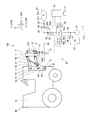
- FIG. 1 is a plan view of a boom sprayer to which a boom displacement device according to a first embodiment of the present invention is applied.
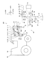
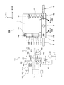
- FIG. 2 is a hydraulic circuit diagram of the boom displacement device according to the first embodiment of the present invention and a side view of the boom sprayer.
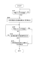
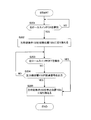
- FIG. 3 is a flowchart of processing executed by the control unit of the boom displacement device according to the first embodiment of the present invention when an operation for lowering the boom is performed.
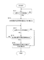
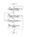
- FIG. 4 is a flowchart of processing executed by the control unit of the boom displacement device according to the first embodiment of the present invention when an operation for raising the boom is performed.
- FIG. 5 is a hydraulic circuit diagram of a boom displacement device and a side view of a boom sprayer according to a modification of the first embodiment of the present invention.
- FIG. 1 is a plan view of a boom sprayer to which a boom displacement device according to a first embodiment of the present invention is applied.
- FIG. 2 is a hydraulic circuit diagram of the boom displacement device according to the first embodiment
- FIG. 6 is a flowchart of processing executed by the control unit of the boom displacement device according to the modification of the first embodiment of the present invention when an operation for lowering the boom is performed.
- FIG. 7 is a flowchart of processing executed by the control unit of the boom displacement device according to the modification of the first embodiment of the present invention when an operation for raising the boom is performed.
- FIG. 8 is a hydraulic circuit diagram of a boom displacement device and a front view of a boom sprayer according to the second embodiment of the present invention.
- FIG. 9 is a flowchart of a process executed by the control unit of the boom displacement device according to the second embodiment of the present invention when an operation to roll the boom to the left is performed.
- FIG. 10 is a flowchart of a process executed by the control unit of the boom displacement device according to the second embodiment of the present invention when an operation to roll the boom to the right is performed.
- FIG. 11 is a hydraulic circuit diagram of a boom displacement device and a front view of a boom sprayer according to a modification of the second embodiment of the present invention.
- FIG. 12 is a flowchart of processing executed by the control unit of the boom displacement device according to the modified example of the second embodiment of the present invention when an operation to roll the boom to the left is performed.
- FIG. 13 is a flowchart of processing executed by the control unit of the boom displacement device according to the modified example of the second embodiment of the present invention when an operation of rolling the boom to the right is performed.
- the X axis is the longitudinal direction of the vehicle (substantially horizontal vertical direction)
- the Y axis is the lateral direction of the vehicle (substantially horizontal horizontal direction)
- the embodiment will be described on the assumption that the shaft extends in the vertical direction (substantially vertical direction) of the vehicle
- the rotation direction about the X axis is the roll direction
- the rotation direction about the Z axis is the yaw direction.
- the boom raising / lowering apparatus 40 which displaces a boom to an up-down direction with respect to a vehicle body corresponds to a boom displacement apparatus.
- the boom sprayer 100 provided with the boom raising / lowering apparatus 40 is demonstrated.
- FIG. 1 is a plan view of the boom sprayer 100
- FIG. 2 is a side view of the boom sprayer 100.
- a boom sprayer 100 shown in FIG. 1 is an agricultural working machine that is mounted on the front side of a work vehicle 90 that travels in a field and sprays a chemical solution such as a control liquid or liquid fertilizer from the work vehicle 90.
- the boom sprayer 100 includes a pair of booms 4 that extend from the work vehicle 90 to the left and right.
- a nozzle (not shown) for spraying a chemical solution is attached to the boom 4.
- the chemical solution is sprayed from the nozzles of the boom 4 while the work vehicle 90 travels in the field.
- the boom sprayer 100 includes a pair of link arms 2 attached to a vehicle body 91 of a work vehicle 90, a lifting platform 3 supported by the link arm 2 so as to be movable up and down with respect to the vehicle body 91, A roll base 5 rotatably supported about the X axis, and left and right booms 4 extending from the roll base 5 to the left and right sides of the vehicle body 91 (Y-axis direction).
- the boom 4 is cantilevered so that its base end 4a can rotate in the yaw direction (around the Z axis) via a storage hinge (not shown) with respect to the roll base 5, and its tip 4b is a free end.
- the distal end side frame 16 having the distal end portion 4 b is supported by the proximal end side frame 15 having the proximal end portion 4 a so as to be extendable and contractible.
- FIG. 1 shows the unfolded state in which the left and right booms 4 extend in the horizontal direction of the vehicle body 91.
- the boom 4 is retracted from the unfolded state shown in FIG. 1 and stored in the proximal frame 15 after being retracted, and then rotated backward via the storage hinge.
- the boom 4 is folded and stored so as to extend in the front-rear direction along the side of the vehicle body 91.
- the roll table 5 is supported by the lift table 3 via a support shaft 6 so as to be rotatable in the roll direction.
- a cylindrical pin member is used for the support shaft 6.
- a rotation cylinder 141 that expands and contracts in conjunction with the rotation of the boom 4 in the left-right roll direction, and a position that is symmetrical to the rotation cylinder 141 with the support shaft 6 interposed therebetween.
- a metal spring 80 that expands and contracts in conjunction with the rotation of the boom 4 in the left-right roll direction.
- the rotating cylinder 141 and the metal spring 80 are provided to suppress vibration of the boom 4 in the roll direction. By these, the vibration which the top part 4b of the boom 4 shakes to an up-down direction is suppressed, and it is prevented that the front-end
- the link arm 2 has an upper link 21 and a lower link 22 that extend in parallel with each other, as shown in FIG.
- the upper link 21 has a base end portion rotatably connected to the vehicle body 91 via the pin 12, and a distal end portion rotatably connected to the lifting platform 3 via the pin 11.
- the lower link 22 has a base end portion rotatably connected to the vehicle body 91 via the pin 14, and a distal end portion rotatably connected to the lifting platform 3 via the pin 13.
- FIG. 2 shows a hydraulic circuit diagram of the boom lifting device 40.
- the boom elevating device 40 is interposed between the vehicle body 91 and the upper link 21, and operates on the elevating cylinder 41 as a hydraulic cylinder that expands and contracts when hydraulic oil as working fluid is supplied and discharged.
- a hydraulic pump 51 as a pump for supplying oil, a tank T to which hydraulic oil discharged from the elevating cylinder 41 is guided, and a supply / discharge passage 56 as a fluid path through which hydraulic oil flows into and out of the elevating cylinder 41 flows.
- an accumulator 61 that is connected to the supply / discharge passage 56 via the branch passage 64 and stores pressurized hydraulic oil.
- a pair of elevating cylinders 41 is provided on both the left and right sides of the vehicle body 91.
- Each raising / lowering cylinder 41 raises / lowers the boom 4 and the raising / lowering stand 3 by expanding / contracting synchronously.
- the raising / lowering cylinder 41 uses hydraulic fluid as a working fluid, it may replace with hydraulic fluid and may use hydraulic fluids, such as a water-soluble alternative liquid, for example, and may use gas.
- the elevating cylinder 41 includes a cylinder tube 42 filled with hydraulic oil, a piston rod 43 inserted into the cylinder tube 42 so as to be able to advance and retract, and a piston 44 provided at a base end portion of the piston rod 43.
- the base end portion of the cylinder tube 42 is rotatably connected to the vehicle body 91 via the pillow ball 47
- the tip end portion of the piston rod 43 is rotatably connected to the upper link 21 via the pillow ball 48.
- the pillow balls 47 and 48 are constituted by, for example, a ball and a spherical bearing. The connecting portion of the elevating cylinder 41 is prevented from being twisted by the pillow balls 47 and 48.
- the inside of the cylinder tube 42 is partitioned into a piston side chamber 45 and a rod side chamber 46 by a piston 44.
- the piston 44 is formed with a flow path 44 a that allows the hydraulic oil to flow back and forth between the piston side chamber 45 and the rod side chamber 46.
- the elevating cylinder 41 is a so-called single acting fluid pressure cylinder that expands when hydraulic oil is supplied from the hydraulic pump 51 to the piston side chamber 45 and contracts when hydraulic oil is discharged from the piston side chamber 45.
- the lifting cylinder 41 is not limited to this, and hydraulic oil is supplied to and discharged from the ram type single-acting fluid pressure cylinder having no piston, both the piston side chamber 45 and the rod side chamber 46, or A double-acting fluid pressure cylinder may be used in which hydraulic oil is supplied and discharged only to the piston side chamber 45 and the rod side chamber 46 is connected to the tank T.
- each elevating platform 3 and the boom 4 are moved up and down as each elevating cylinder 41 expands and contracts and each link arm 2 rotates.
- a guide rail extending in the Z-axis direction may be provided at the front portion of the vehicle body 91, and the lifting platform 3 may be supported by the guide rail so as to be movable up and down in the Z-axis direction.
- each raising / lowering cylinder 41 is interposed between the vehicle body 91 and the raising / lowering stand 3, and changes the height of the raising / lowering stand 3 with respect to the vehicle body 91 by extending / contracting.
- the hydraulic pump 51 is driven by an engine or an electric motor (not shown), and supplies hydraulic oil stored in the tank T to the piston side chamber 45.
- the boom elevating device 40 further includes a direction switching valve 52 as a switching valve for switching between communication and blocking between the lifting cylinder 41 and the hydraulic pump 51 and communication and blocking between the lifting cylinder 41 and the tank T.
- the direction switching valve 52 includes an extension position 52a as a communication position for extending the lift cylinder 41, a contraction position 52b as a communication position for contracting the lift cylinder 41, and a stop position 52c as a blocking position for stopping the lift cylinder 41.
- the electromagnetic switching valve has three positions.
- One end of the supply / discharge passage 56 is connected to the direction switching valve 52 and the other end is connected to the piston side chamber 45 of the elevating cylinder 41.
- An operation check valve 53 is interposed in the supply / discharge passage 56.
- a supply / discharge passage 56 is connected to the direction switching valve 52, a supply passage 55 that guides hydraulic oil discharged from the hydraulic pump 51, a discharge passage 57 that returns the hydraulic oil to the tank T, and an operation check valve 53.
- An operating passage 59 communicating with the pilot pressure chamber is connected.
- the supply passage 55 and the discharge passage 57 are connected by a relief passage 58, and the relief passage 58 is provided with a relief valve 54 that opens when the hydraulic pressure of the supply passage 55 exceeds a set pressure.
- the supply passage 55, the discharge passage 57, the operation passage 59, and the supply / discharge passage 56 are all in communication. Accordingly, all the hydraulic oil supplied from the hydraulic pump 51 through the supply passage 55 is returned to the tank T. At this time, the pressure of the operating passage 59 becomes equal to that of the tank T, and the operating check valve 53 is closed by the biasing force of the spring. Thereby, the expansion / contraction operation of the pair of lifting cylinders 41 is stopped, and the height of the boom 4 with respect to the vehicle body 91 is maintained. As described above, the height of the boom 4 with respect to the vehicle body 91, that is, the height of the boom 4 with respect to the crop in the field can be adjusted by extending and retracting the lifting cylinder 41.
- the accumulator 61 has an oil chamber 61a connected to the piston-side chamber 45 and a spring chamber 61b that applies pressure to the oil chamber 61a.
- the spring chamber 61b is a gas chamber in which a pressurized gas such as nitrogen is sealed, and applies a gas pressure to the liquid surface that is a boundary surface with the oil chamber 61a.
- a free piston that partitions the oil chamber 61a and the spring chamber 61b may be accommodated in the accumulator 61. Further, the free piston that partitions the oil chamber 61a and the spring chamber 61b may be accommodated in the accumulator 61, and the spring may be accommodated in the spring chamber 61b.
- a pressure may be applied to the oil chamber 61a using a spring.
- the characteristics of the accumulator 61 are set by adjusting the gas pressure in the spring chamber 61b, the volume of the accumulator 61, and the like.
- the oil chamber 61 a is connected to a branch passage 64 that branches from between the piston side chamber 45 and the operation check valve 53 in the supply / discharge passage 56. That is, the oil chamber 61 a and the piston side chamber 45 communicate with each other through the supply / discharge passage 56 and the branch passage 64.
- the branch passage 64 is provided with a damping valve 62 that imparts resistance to the hydraulic fluid that travels between the piston side chamber 45 and the accumulator 61, and an opening / closing valve 63 that opens and closes the branch passage 64 is adjacent to the damping valve 62.
- the on-off valve 63 is an electromagnetic on-off valve having a communication position 63a that allows communication between the piston-side chamber 45 and the accumulator 61 and a blocking position 63b that blocks communication between the piston-side chamber 45 and the accumulator 61.
- the on-off valve 63 is in the communication position 63a, and the piston side chamber 45 and the accumulator 61 are in communication with each other.
- the hydraulic oil flows back and forth between the piston side chamber 45 and the oil chamber 61a of the accumulator 61.
- the hydraulic fluid that has flowed into the oil chamber 61a is pushed back to the piston-side chamber 45 by the gas pressure in the spring chamber 61b.
- resistance is given by the damping valve 62 to the flow of the hydraulic oil flowing back and forth between the piston side chamber 45 and the oil chamber 61a.
- a damping force is generated, and the vertical vibration of the boom 4 is suppressed.
- the open / close valve 63 is used when it is not necessary to reduce the vibration of the boom 4 or when it is not desired to extend and retract the lifting cylinder 41, such as when traveling on a road surface with little vibration or when the boom 4 is stored. Can be switched to the blocking position 63b by the operator.
- the oil chamber 61 a and the piston side chamber 45 may be directly connected by a passage independent of the supply / discharge passage 56.
- the damping valve 62 and the on-off valve 63 are provided in the independent passages.
- the boom elevating device 40 further includes a pressure detector 72 as a state detector that detects that the state of the elevating cylinder 41 is a state in which a predetermined amount or more of hydraulic oil is discharged or supplied, and the pressure detector 72 And a controller 70 as a control unit that controls the direction switching valve 52 based on the detection result.
- a pressure detector 72 as a state detector that detects that the state of the elevating cylinder 41 is a state in which a predetermined amount or more of hydraulic oil is discharged or supplied
- a controller 70 as a control unit that controls the direction switching valve 52 based on the detection result.
- the pressure detector 72 is provided in the supply / discharge passage 56 between the piston side chamber 45 and the operation check valve 53 and detects the pressure of the hydraulic oil flowing through the supply / discharge passage 56.
- the pressure detector 72 is a pressure switch that outputs a contact signal when the pressure in the supply / discharge passage 56 is not within a predetermined range. For example, the pressure detector 72 is turned off when the pressure in the supply / discharge passage 56 is within a predetermined range, and is turned on when the pressure in the supply / discharge passage 56 exceeds or falls below a predetermined range. Become.
- the controller 70 is a microcomputer including a central processing unit (CPU), a read-only memory (ROM), a random access memory (RAM), and an input / output interface (I / O interface).
- the read-only memory stores in advance a control program executed by the central processing unit, and the random access memory stores data in the processing of the central processing unit.
- the I / O interface is used for input / output of information with a device connected to the controller 70.
- the controller 70 receives an output signal from the pressure detector 72 and a signal from the operation panel 71 operated by the operator.
- the operation panel 71 is provided with a boom raising switch (not shown) that is operated when the boom 4 is raised with respect to the vehicle body 91 and a boom lowering switch that is operated when the boom 4 is lowered with respect to the vehicle body 91.
- These switches may be a button type that is turned on or off, or may be a toggle type.
- you may provide the stop switch which stops operation of the boom 4 separately from a boom raising switch and a boom lowering switch.
- the switch may be a lever type that operates to raise and lower the boom 4.
- the controller 70 determines that the raising switch is turned on when the lever is tilted to one side, determines that the lowering switch is turned on when the lever is tilted to the other side, and the lever is in the neutral state. It is determined that the up switch and the down switch are turned off.
- the control described later is executed based on the signal from the pressure detector 72 and the signal from the operation panel 71, and the positions of the direction switching valve 52 and the on-off valve 63 are switched by the controller 70.
- the controller 70 is not limited to a microcomputer, and may have any configuration as long as the position of the direction switching valve 52 and the on-off valve 63 can be switched appropriately according to the operation of the operator or the detection result of the pressure detector 72. There may be. For example, a relay, an electronic timer, a comparator, or the like may be simply combined.
- the operation panel 71 may be integrated with the controller 70.
- the piston side chamber 45 of the elevating cylinder 41 and the accumulator 61 are normally in communication. Therefore, when the operation of lowering the boom 4 is performed and the operation of lowering the boom 4 is continued even after the hydraulic oil is discharged from the piston-side chamber 45 by a predetermined amount or more and the elevating cylinder 41 is contracted to the maximum, Is discharged to the tank T.
- the hydraulic oil supplied from the hydraulic pump 51 is first supplied to the accumulator 61. That is, the hydraulic oil is supplied to the elevating cylinder 41 that raises the boom 4 after the accumulator 61 is filled with the hydraulic oil.
- the controller 70 of the boom elevating device 40 causes the pressure detected by the pressure detector 72 to be equal to or lower than a predetermined pressure while the operation of lowering the boom 4 is performed by the operator. Then, the control for shutting off the communication between the accumulator 61 and the tank T is executed by switching the direction switching valve 52 to the stop position 52c.
- the supply / exhaust passage 56 provided with the pressure detector 72 communicates with the tank T when the direction switching valve 52 is switched to the contracted position 52b, so that the pressure in the supply / exhaust passage 56 decreases to some extent.
- the piston-side chamber 45 to which the supply / discharge passage 56 communicates is compressed by the weight of the lowering boom 4 and the lifting / lowering base 3.
- the pressure of 56 changes with a substantially constant magnitude.
- the accumulator 61 is connected to the supply / discharge passage 56 via a damping valve 62 that also functions as a throttle. For this reason, even if the pressure in the piston side chamber 45 and the supply / discharge passage 56 decreases, the damping valve 62 prevents the hydraulic oil in the accumulator 61 from being immediately discharged to the tank T. Therefore, even if the communication between the accumulator 61 and the tank T is cut off after the pressure drop in the supply / discharge passage 56 is detected, the hydraulic oil in the accumulator 61 is sufficiently suppressed from being discharged to the tank T. it can.
- the flow area of the branch passage 64 is temporarily reduced so that the hydraulic oil flows into and out of the accumulator 61. May be suppressed.
- hydraulic oil is stored in the accumulator 61, the hydraulic oil supplied from the hydraulic pump 51 is stored in the accumulator 61 even if the operator performs an operation to raise the boom 4 following the operation to lower the boom 4. Instead, it flows into the lift cylinder 41. For this reason, the boom 4 can be displaced with high responsiveness to the operation of the operator.
- the hydraulic pump 51 is continued.
- the hydraulic oil supplied from is filled in the accumulator 61.
- Filling the accumulator 61 with hydraulic oil is continued until the hydraulic oil supply pressure in the supply passage 55 reaches the set pressure of the relief valve 54.
- the hydraulic oil in the accumulator 61 is first discharged to the tank T.
- the hydraulic oil in the lifting cylinder 41 that lowers the boom 4 is discharged after the hydraulic oil stored in the accumulator 61 falls below a predetermined amount, that is, the hydraulic oil supply pressure in the supply / discharge passage 56 decreases to some extent. After that.
- the controller 70 of the boom elevating device 40 is configured such that the pressure detected by the pressure detector 72 is equal to or higher than a predetermined pressure while the operator raises the boom 4. Then, the control for shutting off the communication between the accumulator 61 and the hydraulic pump 51 is executed by switching the direction switching valve 52 to the stop position 52c.
- the supply / discharge passage 56 provided with the pressure detector 72 communicates with the hydraulic pump 51 when the direction switching valve 52 is switched to the extended position 52a, the pressure in the supply / discharge passage 56 rises to some extent. Then, until the boom 4 and the lifting platform 3 reach the highest position, the pressure in the supply / discharge passage 56 changes at a substantially constant level in order to raise the boom 4 and the lifting platform 3.
- the pressure in the supply / discharge passage 56 further increases and becomes equal to or higher than a predetermined pressure. That is, by detecting whether or not the pressure in the supply / discharge passage 56 has become equal to or higher than a predetermined pressure, it is detected that the lift cylinder 41 is in the maximum extension state and the boom 4 and the lift base 3 have reached the highest position. Can do.
- the accumulator 61 is connected to the supply / discharge passage 56 via a damping valve 62 that also functions as a throttle. For this reason, even if the pressure in the piston side chamber 45 and the supply / discharge passage 56 rises, the damping valve 62 prevents the hydraulic oil from immediately flowing into the accumulator 61. Therefore, even if the communication between the accumulator 61 and the hydraulic pump 51 is interrupted after the increase in the pressure in the supply / discharge passage 56 is detected, it is possible to sufficiently suppress excessive supply of hydraulic oil into the accumulator 61. .
- the flow area of the branch passage 64 is temporarily reduced so that the hydraulic oil flows into and out of the accumulator 61. May be suppressed.
- FIG. 3 is a flowchart showing a processing procedure of the controller 70 that is executed when an operation for lowering the boom 4 with respect to the vehicle body 91 is performed by an operator. It is the flowchart which showed the procedure of the process of the controller 70 performed when operation to raise is performed by an operator.
- step S101 the controller 70 detects whether or not the lowering switch is operated from OFF to ON by the operator.
- the operation panel 71 outputs a signal corresponding to the operation to the controller 70 when the operator operates the lowering switch.
- step S101 When it is detected in step S101 that the lowering switch has been turned on, the process proceeds to step S102, where the controller 70 switches the direction switching valve 52 to the contracted position 52b and causes the piston side chamber 45 and the tank T to communicate with each other.
- the hydraulic oil in the piston side chamber 45 is discharged to the tank T through the supply / discharge passage 56 and the discharge passage 57, and the elevating cylinder 41 contracts. In conjunction with the contraction of the lifting cylinder 41, the boom 4 and the lifting platform 3 start to descend.
- step S103 the controller 70 detects whether or not the lowering switch is operated from on to off by the operator. Usually, the operator turns off the lowering switch while watching the distance between the boom 4 and the crop when the height of the boom 4 reaches an optimum height for spraying agricultural chemicals and the like.
- step S105 the controller 70 switches the direction switching valve 52 to the stop position 52c and blocks communication between the piston side chamber 45 and the tank T.
- the piston side chamber 45 is filled with a predetermined amount of hydraulic oil, and the height of the boom 4 with respect to the vehicle body 91 is maintained.
- step S104 the controller 70 determines whether or not the pressure detector 72 outputs a contact signal, that is, the pressure detector 72. It is determined whether or not the pressure in the supply / discharge passage 56 detected by the above is equal to or lower than a predetermined pressure.
- the elevating cylinder 41 contracts most and the boom 4 Is when the minimum position is reached. If this state is maintained, the hydraulic oil in the accumulator 61 is also discharged, and a delay occurs when the boom 4 is raised.
- step S105 when the pressure detected by the pressure detector 72 becomes equal to or lower than a predetermined value and a contact signal is output from the pressure detector 72, the process proceeds to step S105, and the direction switching valve 52 is stopped. Switching to 52c cuts off the communication between the piston side chamber 45 and the tank T and the communication between the accumulator 61 and the tank T.
- step S104 If the contact signal is not output from the pressure detector 72 in step S104, the elevating cylinder 41 is still in a contractible state, so that the process returns to step S103, and whether or not the lowering switch is again operated from on to off by the operator. To detect.
- the boom 4 is lowered to a desired height, and the hydraulic oil in the accumulator 61 is prevented from being discharged to the tank T after the elevating cylinder 41 is contracted most. Is done.
- step S111 the controller 70 detects whether or not the raising switch has been operated from OFF to ON by the operator.
- the operation panel 71 outputs a signal corresponding to the operation to the controller 70.
- step S111 When it is detected in step S111 that the raising switch has been turned on, the process proceeds to step S112, where the controller 70 switches the direction switching valve 52 to the extended position 52a and causes the piston side chamber 45 and the hydraulic pump 51 to communicate with each other.
- step S113 the controller 70 detects whether or not the raising switch has been operated from on to off by the operator. Normally, the operator turns off the ascent switch when the height of the boom 4 reaches an optimum height for spraying agricultural chemicals or the like while observing the distance between the boom 4 and the crop.
- step S115 the controller 70 switches the direction switching valve 52 to the stop position 52c and cuts off the communication between the piston side chamber 45 and the hydraulic pump 51.
- the piston side chamber 45 is filled with a predetermined amount of hydraulic oil, and the height of the boom 4 with respect to the vehicle body 91 is maintained.
- step S113 determines whether or not the raising switch is turned off. If it is not detected in step S113 that the raising switch is turned off, the process proceeds to step S114, and the controller 70 determines whether or not the pressure detector 72 outputs a contact signal, that is, the pressure detector 72. It is determined whether or not the pressure in the supply / discharge passage 56 detected by the above is equal to or higher than a predetermined pressure.
- step S115 when the pressure detected by the pressure detector 72 becomes equal to or higher than a predetermined value and a contact signal is output from the pressure detector 72, the process proceeds to step S115 and the direction switching valve 52 is stopped. Switching to 52c cuts off the communication between the piston side chamber 45 and the hydraulic pump 51 and the communication between the accumulator 61 and the hydraulic pump 51.
- step S114 If no contact signal is output from the pressure detector 72 in step S114, the lift cylinder 41 is still in an extendable state, so the process returns to step S113, and whether the lift switch has been operated again from on to off by the operator. To detect.
- the boom 4 is raised to a desired height, and after the elevating cylinder 41 is fully extended, the hydraulic oil is prevented from being excessively supplied into the accumulator 61.
- the lifting cylinder 41 when the hydraulic oil is discharged or supplied to the lifting cylinder 41 in order to displace the boom 4, the lifting cylinder 41 is discharged or supplied with a predetermined amount or more of hydraulic oil.
- the controller 70 executes control for blocking the flow of hydraulic oil into and out of the accumulator 61.
- the boom 4 can be displaced with high responsiveness as a result of the elevating cylinder 41 rapidly expanding and contracting in accordance with the operation of the operator.
- the pressure detector 72 is a pressure switch.
- the pressure detector 72 may be a pressure sensor capable of detecting an absolute pressure.
- the controller 70 compares the pressure value detected by the pressure detector 72 with the stored first pressure value in step S104 of FIG. 3, and the detected pressure value falls below the first pressure value.
- the direction switching valve 52 is switched to the stop position 52c, and the pressure value detected by the pressure detector 72 is compared with the second pressure value higher than the first pressure value in step S114 of FIG. When the determined pressure value exceeds the second pressure value, the direction switching valve 52 is switched to the stop position 52c.
- the controller 70 determines whether or not the boom 4 has reached the lowest position or the highest position based on whether or not the contact signal is output from the pressure detector 72. Instead, it may be determined whether or not the boom 4 has reached the lowest position or the vicinity of the highest position based on a detection value of a stroke sensor that detects the amount of expansion / contraction of the elevating cylinder 41. Further, in order to determine whether or not the boom 4 has reached the lowest position or the vicinity of the highest position, a stroke switch or a link arm 2 that emits a signal when the elevating cylinder 41 is in the most contracted or most extended state.
- a contact-type or non-contact-type limit switch that emits a signal when the position becomes the lowest position or the vicinity of the highest position, and an angle sensor that detects the angle of the link arm 2 with respect to the vehicle body 91 may be used.
- a combination of a plurality of the sensors and switches described above may be used to determine whether or not the boom 4 has reached the lowest position or the vicinity of the highest position based on the detected values.
- the state detection unit when a stroke switch or a limit switch is used as the state detection unit, it is set so that the contact signal is generated before the lifting cylinder 41 is contracted or extended most, that is, the boom 4 is at the lowest position or the highest position. It is possible to set so that the contact signal is generated with a margin before reaching. For this reason, compared with the case where the pressure detector 72 that outputs the pressure after the elevating cylinder 41 is contracted or extended as a detection value is used as the state detection unit, the hydraulic oil is discharged from the accumulator 61 or the accumulator. It is possible to reliably prevent the hydraulic oil from being excessively supplied to 61.
- the boom 4 is displaced downward by discharging hydraulic oil from the elevating cylinder 41.
- the boom 4 may be displaced upward by discharging hydraulic oil from the elevating cylinder 41.
- the direction switching valve 52 is an electromagnetic switching valve whose position is switched by electromagnetic force.
- the direction switching valve 52 may be a manual switching valve that is manually switched by an operator.
- the case where the direction switching valve 52 is a manual switching valve will be described with reference to FIGS.
- the operator operates the lever 52d interlocked with the direction switching valve 52 to switch the boom 4 to the extended position 52a and to lower the boom 4
- the controller 70 detects to which position the direction switching valve 52 has been operated by the operator in accordance with the detection value of the position sensor 52e that detects the position of the direction switching valve 52.
- the direction switching valve 52 when the direction switching valve 52 is a manual switching valve, the direction switching valve 52 cannot be switched to the stop position 52c according to the detection value of the pressure detector 72 as in the first embodiment. That is, the communication between the accumulator 61 and the tank T or the hydraulic pump 51 cannot be blocked. Therefore, in this modification, the communication between the accumulator 61 and the tank T or the hydraulic pump 51 is blocked by closing the on-off valve 63.
- FIG. 6 is a flowchart showing a processing procedure of the controller 70 that is executed when an operation of lowering the boom 4 with respect to the vehicle body 91 is performed by an operator. It is the flowchart which showed the procedure of the process of the controller 70 performed when operation to raise is performed by an operator.
- step S121 the controller 70 detects whether or not the direction switching valve 52 has been switched to the contracted position 52b based on the detection value of the position sensor 52e.
- the direction switching valve 52 is switched to the contracted position 52b, the piston side chamber 45 and the tank T communicate with each other, and the hydraulic oil in the piston side chamber 45 is discharged to the tank T through the supply / discharge passage 56 and the discharge passage 57. 41 contracts. In conjunction with the contraction of the lifting cylinder 41, the boom 4 and the lifting platform 3 start to descend.
- step S121 When it is detected in step S121 that the direction switching valve 52 has been switched to the contracted position 52b, the process proceeds to step S122, and the controller 70 detects whether or not the direction switching valve 52 has been switched to the stop position 52c by the operator. .
- the operator switches the direction switching valve 52 to the stop position 52c when the height of the boom 4 reaches an optimum height for spraying agricultural chemicals or the like while observing the distance between the boom 4 and the crop.
- step S122 if it is not detected in step S122 that the direction switching valve 52 has been switched to the stop position 52c, the process proceeds to step S123, and the controller 70 detects whether or not a contact signal is output from the pressure detector 72.
- the elevating cylinder 41 contracts most and the boom 4 Is when the minimum position is reached. If this state is maintained, the hydraulic oil in the accumulator 61 is also discharged, and a delay occurs when the boom 4 is raised.
- step S124 when the pressure detector 72 detects that the pressure in the supply / exhaust passage 56 is equal to or lower than a predetermined value, the process proceeds to step S124, and the on-off valve 63 is switched to the cutoff position 63b. The communication between the accumulator 61 and the tank T is cut off.
- step S123 If no contact signal is output from the pressure detector 72 in step S123, the elevating cylinder 41 is still in a contractible state, so the process returns to step S122, and the direction switching valve 52 is switched again to the stop position 52c by the operator. It is detected whether or not.
- the boom 4 is lowered to a desired height, and the hydraulic oil in the accumulator 61 is prevented from being discharged to the tank T after the elevating cylinder 41 is contracted most. Is done.
- step S131 the controller 70 detects whether or not the direction switching valve 52 has been switched to the extended position 52a by the operator based on the detection value of the position sensor 52e.
- the direction switching valve 52 is switched to the extended position 52a
- the piston side chamber 45 and the hydraulic pump 51 communicate with each other
- hydraulic fluid is supplied to the piston side chamber 45 through the supply / discharge passage 56 and the supply passage 55
- the elevating cylinder 41 extends. To do.
- the boom 4 and the lifting platform 3 begin to rise.
- step S131 When it is detected in step S131 that the direction switching valve 52 has been switched to the extended position 52a, the process proceeds to step S132, and the controller 70 detects whether or not the direction switching valve 52 has been switched to the stop position 52c by the operator. .
- the operator switches the direction switching valve 52 to the stop position 52c when the height of the boom 4 reaches an optimum height for spraying agricultural chemicals or the like while observing the distance between the boom 4 and the crop.
- step 132 when the direction switching valve 52 is switched to the stop position 52c by the operator, the communication between the piston side chamber 45 and the hydraulic pump 51 is blocked. At this time, since the communication between the accumulator 61 and the hydraulic pump 51 is also blocked, there is no possibility that the hydraulic oil is excessively stored in the accumulator 61. For this reason, when it is detected in step 132 that the direction switching valve 52 has been switched to the stop position 52c, the controller 70 once ends the process.
- step S132 determines whether or not the direction switching valve 52 has been switched to the stop position 52c. If it is not detected in step S132 that the direction switching valve 52 has been switched to the stop position 52c, the process proceeds to step S133, and the controller 70 detects whether or not a contact signal is output from the pressure detector 72.
- step S134 when the pressure detector 72 detects that the pressure in the supply / exhaust passage 56 is equal to or higher than a predetermined value, the process proceeds to step S134, and the on-off valve 63 is switched to the cutoff position 63b. The communication between the accumulator 61 and the hydraulic pump 51 is cut off.
- step S133 If no contact signal is output from the pressure detector 72 in step S133, the elevating cylinder 41 is still in an extendable state, so the process returns to step S132, and the direction switching valve 52 is switched again to the stop position 52c by the operator. It is detected whether or not.
- the boom 4 is raised to a desired height, and after the elevating cylinder 41 is fully extended, the hydraulic oil is prevented from being excessively supplied into the accumulator 61.
- a boom sprayer 200 according to a second embodiment of the present invention will be described with reference to FIG. below, it demonstrates centering on a different point from the said 1st Embodiment, the same code
- the basic configuration of the boom sprayer 200 is the same as that of the boom sprayer 100 according to the first embodiment.
- the boom elevating device 40 that displaces the boom 4 in the vertical direction with respect to the vehicle body 91 corresponds to the boom displacement device.
- the boom rotation device 140 that displaces the boom 4 in the roll direction corresponds to the boom displacement device.
- the right rotation direction around the X axis as viewed from the rear of the work vehicle 90 is referred to as the right roll direction
- the left rotation direction is referred to as the left roll direction.
- the boom rotation device 140 is interposed between the lifting platform 3 and the roll platform 5, and serves as a hydraulic cylinder that expands and contracts when hydraulic fluid as working fluid is supplied and discharged.
- the boom rotation device 140 has a hydraulic circuit similar to the boom lifting device 40 of the first embodiment.
- Rotating cylinder 141 is provided at a position symmetrical to metal spring 80 with support shaft 6 in between.
- the rotating cylinder 141 is rotated to rotate the roll base 5 and the boom 4 around the support shaft 6.
- the rotating cylinder 141 and the metal spring 80 function as a vibration damping device that suppresses vibration of the boom 4 in the roll direction.
- the rotating cylinder 141 includes a cylinder tube 142 filled with hydraulic oil, a piston rod 143 inserted into the cylinder tube 142 so as to freely advance and retract, and a piston 144 provided at a base end portion of the piston rod 143.
- the base end portion of the cylinder tube 142 is rotatably connected to the lifting / lowering table 3 via the pillow ball 147, and the tip end portion of the piston rod 143 is rotatable to the roll table 5 via the pillow ball 148.
- the pillow balls 147 and 148 are constituted by, for example, balls and spherical bearings. The connecting portion of the rotating cylinder 141 is prevented from being twisted by the pillow balls 147 and 148.
- the inside of the cylinder tube 142 is partitioned by a piston 144 into a piston side chamber 145 and a rod side chamber 146.
- the piston 144 is formed with a flow path 144 a that allows the hydraulic oil to flow back and forth between the piston side chamber 145 and the rod side chamber 146.
- the rotating cylinder 141 is a so-called single acting fluid pressure cylinder that expands when hydraulic oil is supplied from the hydraulic pump 51 to the piston side chamber 145 and contracts when hydraulic oil is discharged from the piston side chamber 145.
- the rotating cylinder 141 is not limited to this, and hydraulic oil is supplied to and discharged from the ram type single-acting fluid pressure cylinder having no piston, both the piston side chamber 145 and the rod side chamber 146, or Alternatively, a double-acting fluid pressure cylinder may be used in which hydraulic oil is supplied and discharged only to the piston side chamber 145 and the rod side chamber 146 is connected to the tank T.
- the hydraulic pump 51 supplies hydraulic oil stored in the tank T to the piston side chamber 145 and is shared with the boom lifting device 40.
- the boom rotation device 140 further includes a direction switching valve 152 as a switching valve for switching between communication and blocking between the rotation cylinder 141 and the hydraulic pump 51 and communication and blocking between the rotation cylinder 141 and the tank T.
- a direction switching valve 152 as a switching valve for switching between communication and blocking between the rotation cylinder 141 and the hydraulic pump 51 and communication and blocking between the rotation cylinder 141 and the tank T.
- the direction switching valve 152 includes an extension position 152a as a communication position for extending the rotation cylinder 141, a contraction position 152b as a communication position for contracting the rotation cylinder 141, and a stop as a blocking position for stopping the rotation cylinder 141.
- the electromagnetic switching valve has three positions: a position 152c.
- the supply / discharge passage 156 has one end connected to the direction switching valve 152 and the other end connected to the piston side chamber 145 of the rotating cylinder 141.
- An operation check valve 153 is interposed in the supply / discharge passage 156.
- a supply / discharge passage 156 is connected to the direction switching valve 152, a supply passage 55 that guides hydraulic oil discharged from the hydraulic pump 51, a discharge passage 57 that returns the hydraulic oil to the tank T, and an operation check valve 153.
- An operating passage 159 communicating with the pilot pressure chamber is connected.
- the supply passage 55 and the discharge passage 57 are shared with the boom lifting device 40.
- the direction switching valve 152 When the direction switching valve 152 is switched to the contracted position 152b, the supply passage 55 and the operation passage 159 are connected, and the supply / discharge passage 156 and the discharge passage 57 are connected. Since the discharge pressure of the hydraulic pump 51 is guided as a pilot pressure to the operation check valve 153 via the operation passage 159, the operation check valve 153 is opened, and the hydraulic oil in the piston side chamber 145 is supplied to the supply / discharge passage 156 and the discharge passage 57. Through the tank T. Thereby, the rotation cylinder 141 contracts, the roll base 5 is rotated in the left roll direction with respect to the vehicle body 91, and the boom 4 is displaced together with the roll base 5 in the left roll direction.
- the accumulator 161 is provided to suppress the vibration of the boom 4 in the left-right roll direction. Since the structure of the accumulator 161 is the same as the accumulator 61 of the boom raising / lowering apparatus 40, the description is abbreviate
- the oil chamber 161 a of the accumulator 161 is connected to a branch passage 164 that branches from between the piston side chamber 145 and the operation check valve 153 in the supply / discharge passage 156. That is, the oil chamber 161 a and the piston side chamber 145 communicate with each other through the supply / discharge passage 156 and the branch passage 164.
- the branch passage 164 is provided with a damping valve 162 that provides resistance to the hydraulic fluid that travels between the piston-side chamber 145 and the accumulator 161, and an open / close valve 163 that opens and closes the branch passage 164 is adjacent to the damping valve 162. Provided.
- the on-off valve 163 is an electromagnetic on-off valve having a communication position 163a that allows communication between the piston-side chamber 145 and the accumulator 161, and a blocking position 163b that blocks communication between the piston-side chamber 145 and the accumulator 161.
- the on-off valve 163 is in the communication position 163a, and the piston side chamber 145 and the accumulator 161 are in communication with each other.
- the hydraulic oil moves between the piston side chamber 145 and the oil chamber 161a of the accumulator 161.
- the hydraulic oil flowing into the oil chamber 161a is pushed back to the piston side chamber 145 by the gas pressure in the spring chamber 161b.
- a resistance is given by the damping valve 162 to the flow of the hydraulic oil flowing back and forth between the piston side chamber 145 and the oil chamber 161a.
- the open / close valve is used when it is not necessary to reduce the vibration of the boom 4 or when it is not desired to extend and retract the rotating cylinder 141, such as when traveling on a road surface with little vibration or when the boom 4 is stored. 163 can be switched to the blocking position 163b by the operator.
- the oil chamber 161 a and the piston side chamber 145 may be directly connected by a passage independent of the supply / discharge passage 156.
- the damping valve 162 and the on-off valve 163 are provided in the independent passages.
- the boom rotation device 140 further includes a pressure detector 172 as a state detection unit that detects that the state of the rotation cylinder 141 is a state in which a predetermined amount or more of hydraulic oil is discharged, and a pressure detector 172. And a controller 70 as a control unit that controls the direction switching valve 152 based on the detection result.
- the pressure detector 172 is provided in the supply / discharge passage 156 between the piston side chamber 145 and the operation check valve 153, and detects the pressure of the hydraulic oil flowing through the supply / discharge passage 156.
- the pressure detector 172 is a pressure switch that outputs a contact signal when the pressure in the supply / discharge passage 156 is not within a predetermined range. For example, the pressure detector 172 is turned off when the pressure in the supply / discharge passage 156 is within a predetermined range, and turned on when the pressure in the supply / discharge passage 156 exceeds or falls below a predetermined range. Become.
- controller 70 Since the controller 70 is shared with the boom elevating device 40, description of its structure is omitted.
- the operation panel 71 includes a right roll switch (not shown) that is operated when the boom 4 is displaced in the right roll direction with respect to the vehicle body 91 and an illustration that is operated when the boom 4 is displaced in the left direction with respect to the vehicle body 91.
- a left roll switch is provided.
- the control described later is executed based on the signal from the pressure detector 172 and the signal from the operation panel 71, and the positions of the direction switching valve 152 and the on-off valve 163 are switched by the controller 70.
- the piston side chamber 145 of the rotating cylinder 141 and the accumulator 161 are normally in communication. For this reason, an operation for displacing the boom 4 in the left roll direction is performed, and an operation for displacing the boom 4 in the left roll direction even after the hydraulic oil is discharged from the piston side chamber 145 by a predetermined amount or more and the rotating cylinder 141 is contracted most. Is continued, the hydraulic oil in the accumulator 161 is discharged to the tank T.
- the hydraulic oil supplied from the hydraulic pump 51 is first supplied to the accumulator 161. The That is, the hydraulic oil is supplied to the rotating cylinder 141 that displaces the boom 4 after the accumulator 161 is filled with the hydraulic oil.
- the controller 70 of the boom rotating device 140 detects the pressure detected by the pressure detector 172 while the operator is performing an operation of displacing the boom 4 in the left roll direction.
- control for blocking communication between the accumulator 161 and the tank T is performed by switching the direction switching valve 152 to the stop position 152c.
- the supply / discharge passage 156 provided with the pressure detector 172 communicates with the tank T when the direction switching valve 152 is switched to the contracted position 152b, the pressure in the supply / discharge passage 56 decreases to some extent.
- the piston chamber 145 communicated with the supply / exhaust passage 156 is in a compressed state by the urging force of the extending metal spring 80. Changes in a magnitude corresponding to the reaction force of the metal spring 80.
- the pressure detector 172 can detect whether or not the state of the rotating cylinder 141 is the most contracted state in which a predetermined amount or more of hydraulic oil has been discharged. Therefore, if the communication between the accumulator 161 and the tank T is cut off based on the detection result of the pressure detector 172, even if the operation of displacing the boom 4 in the left roll direction is continued by the operator, the hydraulic oil in the accumulator 161 Can be prevented from being discharged to the tank T.
- the accumulator 161 is connected to the supply / discharge passage 156 via a damping valve 162 that also functions as a throttle. For this reason, even if the pressure in the piston side chamber 145 and the supply / discharge passage 156 decreases, the damping valve 162 prevents the hydraulic oil in the accumulator 161 from being immediately discharged to the tank T. Therefore, even if the communication between the accumulator 161 and the tank T is interrupted after a decrease in the pressure in the supply / discharge passage 156 is detected, the hydraulic oil in the accumulator 161 is sufficiently suppressed from being discharged to the tank T. it can.
- the damping valve 162 is a variable throttle valve and the operation of displacing the boom 4 is performed by an operator, the flow area of the branch passage 164 is temporarily reduced, so that the hydraulic oil flows into and out of the accumulator 161. May be suppressed.
- an operation for displacing the boom 4 in the right roll direction is performed, and an operation for displacing the boom 4 in the right roll direction even after a predetermined amount or more of hydraulic oil is supplied to the piston side chamber 145 and the rotating cylinder 141 is fully extended. Is continued, the hydraulic oil supplied from the hydraulic pump 51 is filled in the accumulator 161. Filling the accumulator 161 with hydraulic oil is continued until the supply pressure of the hydraulic oil in the supply passage 55 reaches the set pressure of the relief valve 54.
- the hydraulic oil in the accumulator 161 is first discharged to the tank T.
- the hydraulic oil in the rotating cylinder 141 that displaces the boom 4 is discharged after the hydraulic oil stored in the accumulator 161 falls below a predetermined amount, that is, the hydraulic oil supply pressure in the supply / discharge passage 156 is to some extent. After it drops.
- the controller 70 of the boom rotation device 140 detects the pressure detected by the pressure detector 172 while the operator is performing an operation of displacing the boom 4 in the right roll direction.
- the pressure becomes equal to or higher than a predetermined pressure
- the communication between the accumulator 161 and the hydraulic pump 51 is cut off by switching the direction switching valve 152 to the stop position 152c.
- the supply / discharge passage 156 provided with the pressure detector 172 communicates with the hydraulic pump 51 when the direction switching valve 152 is switched to the extended position 152a, the pressure in the supply / discharge passage 56 rises to some extent. Then, until the boom 4 is displaced in the rightmost roll direction, the pressure in the supply / discharge passage 156 changes in a magnitude corresponding to the reaction force of the metal spring 80 in order to compress the metal spring 80.
- the pressure in the supply / discharge passage 156 further increases and becomes equal to or higher than a predetermined pressure. That is, by detecting whether or not the pressure in the supply / discharge passage 156 is equal to or higher than a predetermined pressure, the rotating cylinder 141 is in the most extended state, and the boom 4 is in the most displaced state in the right roll direction. Can be detected.
- the pressure detector 172 it can be detected by the pressure detector 172 whether or not the state of the rotating cylinder 141 is the maximum extended state to which a predetermined amount or more of hydraulic oil is supplied. Therefore, if the communication between the accumulator 161 and the hydraulic pump 51 is cut off based on the detection result of the pressure detector 172, even if the operation of displacing the boom 4 in the right roll direction is continued by the operator, the accumulator 161 is supplied with hydraulic fluid. Can be prevented from being excessively supplied.
- the accumulator 161 is connected to the supply / discharge passage 156 via a damping valve 162 that also functions as a throttle. For this reason, even if the pressure in the piston side chamber 145 and the supply / exhaust passage 156 increases, the damping valve 162 prevents the hydraulic oil from immediately flowing into the accumulator 161. Therefore, even if the communication between the accumulator 161 and the hydraulic pump 51 is interrupted after the increase in the pressure in the supply / discharge passage 156 is detected, it is possible to sufficiently suppress excessive supply of hydraulic oil into the accumulator 161. .
- the damping valve 162 is a variable throttle valve and the operation of displacing the boom 4 is performed by an operator, the flow area of the branch passage 164 is temporarily reduced, so that the hydraulic oil flows into and out of the accumulator 161. May be suppressed.
- FIG. 9 is a flowchart showing a processing procedure of the controller 70 executed when the operator performs an operation for displacing the boom 4 in the left roll direction with respect to the vehicle body 91.
- FIG. 7 is a flowchart showing a procedure of processing performed by a controller 70 that is executed when an operation for displacing a vehicle body 91 in the right roll direction is performed by an operator.
- step S201 the controller 70 detects whether or not the left roll switch has been operated from OFF to ON by the operator.
- the operation panel 71 outputs a signal corresponding to the operation to the controller 70 when the left roll switch is operated by the operator.
- step S201 When it is detected in step S201 that the left roll switch is turned on, the process proceeds to step S202, where the controller 70 switches the direction switching valve 152 to the contracted position 152b and causes the piston side chamber 145 and the tank T to communicate with each other.
- the hydraulic oil in the piston side chamber 145 is discharged to the tank T through the supply / discharge passage 156 and the discharge passage 57, and the rotating cylinder 141 contracts.
- the boom 4 and the roll base 5 start to rotate in the left roll direction with respect to the vehicle body 91.
- step S203 the controller 70 detects whether or not the left roll switch has been operated from on to off by the operator.
- the operator turns off the left roll switch when the inclination of the boom 4 reaches an optimum inclination for spraying agricultural chemicals or the like while looking at the distance between the boom 4 and the crop.
- step S203 When it is detected in step S203 that the left roll switch has been turned off, the process proceeds to step S205, where the controller 70 switches the direction switching valve 152 to the stop position 152c and shuts off the communication between the piston side chamber 145 and the tank T. .
- the piston side chamber 145 is filled with a predetermined amount of hydraulic oil, and the inclination of the boom 4 with respect to the vehicle body 91 is maintained.
- step S204 the controller 70 determines whether or not the pressure detector 172 outputs a contact signal, that is, the pressure detector. It is determined whether or not the pressure in the supply / discharge passage 156 detected by 172 is equal to or lower than a predetermined pressure.
- the rotating cylinder 141 is at its maximum. This is when the boom 4 is contracted and the boom 4 is displaced in the leftmost roll direction. If this state is maintained, the hydraulic oil in the accumulator 161 is also discharged, and a delay occurs when the boom 4 is displaced in the right roll direction.
- step S205 when the pressure detected by the pressure detector 172 becomes a predetermined value or less and a contact signal is output from the pressure detector 172, the process proceeds to step S205, and the direction switching valve 152 is stopped. Switching to 152c cuts off the communication between the piston side chamber 145 and the tank T and the communication between the accumulator 161 and the tank T.
- step S204 if no contact signal is output from the pressure detector 72, the rotating cylinder 141 is still in a contractible state, so the process returns to step S203, and the left roll switch is again operated from on to off by the operator. It is detected whether or not.
- the boom 4 is held at a desired inclination, and the hydraulic oil in the accumulator 161 may be discharged to the tank T after the rotating cylinder 141 is contracted most. Is prevented.
- step S211 the controller 70 detects whether or not the right roll switch has been operated from OFF to ON by the operator.
- the operation panel 71 outputs a signal corresponding to the operation to the controller 70.
- step S211 When it is detected in step S211 that the right roll switch has been turned on, the process proceeds to step S212, where the controller 70 switches the direction switching valve 152 to the extended position 152a, and causes the piston side chamber 145 and the hydraulic pump 51 to communicate with each other.
- step S213 the controller 70 detects whether or not the right roll switch is operated from on to off by the operator. Normally, the operator turns off the right roll switch while viewing the distance between the boom 4 and the crop when the boom 4 is tilted optimally for spraying agricultural chemicals and the like.
- step S213 When it is detected in step S213 that the right roll switch has been turned off, the process proceeds to step S215, where the controller 70 switches the direction switching valve 152 to the stop position 152c and cuts off the communication between the piston side chamber 145 and the hydraulic pump 51. To do.
- the piston side chamber 145 is filled with a predetermined amount of hydraulic oil, and the inclination of the boom 4 with respect to the vehicle body 91 is maintained.
- step S213 if it is not detected in step S213 that the right roll switch is turned off, the process proceeds to step S214, and the controller 70 determines whether or not the pressure detector 172 outputs a contact signal, that is, the pressure detector. It is determined whether or not the pressure in the supply / discharge passage 156 detected by 172 is equal to or higher than a predetermined pressure.
- step S215 when the pressure detected by the pressure detector 172 becomes equal to or higher than a predetermined value and a contact signal is output from the pressure detector 172, the process proceeds to step S215, and the direction switching valve 152 is stopped. Switching to 152c cuts off the communication between the piston side chamber 145 and the hydraulic pump 51 and the communication between the accumulator 161 and the hydraulic pump 51.
- step S214 if no contact signal is output from the pressure detector 72, the rotating cylinder 141 is still in an extendable state, so the process returns to step S213, and the right roll switch is again operated from on to off by the operator. It is detected whether or not.
- the boom 4 is held at a desired inclination, and the hydraulic oil is prevented from being excessively supplied into the accumulator 161 after the rotation cylinder 141 is fully extended. Is done.
- the state of the rotary cylinder 141 is such that a predetermined amount or more of hydraulic oil is present.
- the controller 70 executes control for blocking the flow of hydraulic oil into and out of the accumulator 161.
- the boom 4 can be displaced with good responsiveness as a result of the rotating cylinder 141 rapidly expanding and contracting in accordance with the operation of the operator.
- the pressure detector 172 is a pressure switch.
- the pressure detector 172 may be a pressure sensor that can detect absolute pressure.
- the controller 70 compares the pressure value detected by the pressure detector 172 with the stored third pressure value in step S204 of FIG. 9, and the detected pressure value falls below the third pressure value.
- the direction switching valve 152 is switched to the stop position 152c, and the pressure value detected by the pressure detector 172 is compared with the fourth pressure value higher than the third pressure value in step S214 in FIG. When the selected pressure value exceeds the fourth pressure value, the direction switching valve 152 is switched to the stop position 152c.
- the controller 70 is the position which the boom 4 displaced to the left most roll direction or the position most displaced to the right roll direction based on whether the contact signal was output from the pressure detector 172. It is determined whether or not. Instead of this, it may be determined whether or not the boom 4 has reached the vicinity of the most displaced position based on the detection value of the stroke sensor that detects the amount of expansion / contraction of the rotating cylinder 141. Further, in order to determine whether or not the boom 4 has reached the position most displaced in the left roll direction or the position displaced most in the right roll direction, the rotating cylinder 141 is in the most contracted or most extended state.
- Contact type or non-contact type limiter that generates a signal when the position of the stroke switch or roll base 5 that emits a contact signal when the position of the switch is displaced to the leftmost roll direction or near the position displaced to the rightmost roll direction.
- An angle sensor that detects an inclination angle of the roll base 5 in the switch and roll directions may be used. Further, by combining a plurality of the sensors and switches described above, it is determined whether or not the boom 4 has reached the position most displaced in the left roll direction or near the position displaced in the right roll direction based on the detected values. Also good.
- the state detection unit when a stroke switch or a limit switch is used as the state detection unit, it is set so that the contact signal is issued before the rotating cylinder 141 is contracted or extended most, that is, the boom 4 is moved in the left roll direction. It is possible to set the contact signal with a margin before reaching the most displaced position or the most displaced position in the right roll direction. For this reason, compared with the case where the pressure detector 172 that detects the pressure after the rotation cylinder 141 is contracted or extended to the maximum is used as the state detection unit, the hydraulic oil is discharged from the accumulator 161 or the accumulator 161 is discharged. It is possible to reliably prevent the hydraulic oil from being supplied excessively.
- the rotating cylinder 141 is provided on the left side when viewed from the front of the vehicle body 91.
- the positions of the rotating cylinder 141 and the metal spring 80 may be exchanged, and the rotating cylinder 141 may be provided on the right side when viewed from the front of the vehicle body 91.
- the rotating cylinder 141 and the metal spring 80 are provided with the support shaft 6 interposed therebetween.
- the rotating cylinder 141 has a double rod shape, and the hydraulic pump 51 and the accumulator 161 constituting the boom rotating device 140 are connected to one chamber partitioned by the piston so that hydraulic oil can be supplied and discharged. It is good also as a structure which made the other chamber function like the metal spring 80 by connecting an accumulator to this chamber. In this case, the metal spring 80 can be eliminated.
- the direction switching valve 152 is an electromagnetic switching valve whose position is switched by electromagnetic force.
- the direction switching valve 152 may be a manual switching valve that is manually switched by an operator.
- a case where the direction switching valve 152 is a manual switching valve will be described with reference to FIGS.
- the operator when the operator operates the lever 152d interlocked with the direction switching valve 152 to displace the boom 4 in the right roll direction, the operator switches to the extension position 152a and moves the boom 4 to the left roll. When it is displaced in the direction, it switches to the contracted position 152b, and to keep the boom 4 tilted, it switches to the stop position 152c.
- the controller 70 detects to which position the direction switching valve 152 has been operated by the operator in accordance with the detection value of the position sensor 152e that detects the position of the direction switching valve 152.
- the direction switching valve 152 when the direction switching valve 152 is a manual switching valve, the direction switching valve 152 cannot be switched to the stop position 152c according to the detection value of the pressure detector 172 as in the second embodiment. That is, the communication between the accumulator 161 and the tank T or the hydraulic pump 51 cannot be blocked. Therefore, in this modification, the communication between the accumulator 161 and the tank T or the hydraulic pump 51 is blocked by closing the on-off valve 163.
- FIG. 12 is a flowchart showing a processing procedure of the controller 70 executed when the operator performs an operation for displacing the boom 4 in the left roll direction with respect to the vehicle body 91.
- FIG. 7 is a flowchart showing a procedure of processing performed by a controller 70 that is executed when an operation for displacing a vehicle body 91 in the right roll direction is performed by an operator.
- the controller 70 is executed when the operator switches the position of the direction switching valve 152 to the contracted position 152b and performs an operation of displacing the boom 4 in the left roll direction with respect to the vehicle body 91.
- the processing procedure will be described.
- step S221 the controller 70 detects whether or not the direction switching valve 152 has been switched to the contracted position 152b by the operator based on the detection value of the position sensor 152e.
- the direction switching valve 152 is switched to the contracted position 152b, the piston side chamber 145 and the tank T communicate with each other, and the hydraulic oil in the piston side chamber 145 is discharged to the tank T through the supply / discharge passage 156 and the discharge passage 57, and rotates.
- the cylinder 141 contracts. In conjunction with the contraction of the rotation cylinder 141, the boom 4 and the roll base 5 start to rotate in the left roll direction.
- step S221 When it is detected in step S221 that the direction switching valve 152 has been switched to the contracted position 152b, the process proceeds to step S222, and the controller 70 detects whether or not the direction switching valve 152 has been switched to the stop position 152c by the operator. .
- the operator switches the direction switching valve 152 to the stop position 152c when the inclination of the boom 4 reaches an optimum inclination for spraying agricultural chemicals or the like while observing the distance between the boom 4 and the crop.
- step S222 if it is not detected in step S222 that the direction switching valve 152 has been switched to the stop position 152c, the process proceeds to step S223, and the controller 70 detects whether or not a contact signal is output from the pressure detector 172.
- the rotating cylinder 141 is at its maximum. This is when the boom 4 is contracted and the boom 4 is displaced in the leftmost roll direction. If this state is maintained, the hydraulic oil in the accumulator 161 is also discharged, and a delay occurs when the boom 4 is displaced in the right roll direction.
- step S224 when the pressure detector 172 detects that the pressure in the supply / discharge passage 156 is equal to or lower than a predetermined value, the process proceeds to step S224, and the on-off valve 163 is switched to the cutoff position 163b. The communication between the accumulator 161 and the tank T is cut off.
- step S223 when the contact signal is not output from the pressure detector 172, the rotating cylinder 141 is still in a contractible state. Therefore, the process returns to step S222, and the direction switching valve 152 is switched again to the stop position 152c by the operator. It is detected whether it was done.
- the boom 4 is rotated until a desired inclination is obtained, and the hydraulic oil in the accumulator 161 is discharged to the tank T after the rotation cylinder 141 is contracted to the maximum. Is prevented.
- the controller executed when the operator switches the position of the direction switching valve 152 to the extended position 152 a and performs an operation of displacing the boom 4 in the right roll direction with respect to the vehicle body 91.
- the procedure of the process 70 will be described.
- step S231 the controller 70 detects whether or not the direction switching valve 152 has been switched to the extended position 152a by the operator based on the detection value of the position sensor 152e.
- the direction switching valve 152 is switched to the extended position 152a
- the piston side chamber 145 and the hydraulic pump 51 communicate with each other
- hydraulic oil is supplied to the piston side chamber 145 through the supply / discharge passage 156 and the supply passage 55
- the rotating cylinder 141 is Elongate.
- the boom 4 and the roll base 5 start to rotate in the right roll direction.
- step S231 When it is detected in step S231 that the direction switching valve 152 has been switched to the extended position 152a, the process proceeds to step S232, and the controller 70 detects whether or not the direction switching valve 152 has been switched to the stop position 152c by the operator. .
- the operator switches the direction switching valve 152 to the stop position 152c when the inclination of the boom 4 reaches an optimum inclination for spraying agricultural chemicals or the like while observing the distance between the boom 4 and the crop.
- step 232 when the direction switching valve 152 is switched to the stop position 152c by the operator, the communication between the piston side chamber 145 and the hydraulic pump 51 is blocked. At this time, since the communication between the accumulator 161 and the hydraulic pump 51 is also blocked, there is no possibility that the hydraulic oil is excessively stored in the accumulator 161. For this reason, when it is detected in step 232 that the direction switching valve 152 has been switched to the stop position 152c, the controller 70 once ends the process.
- step S232 if it is not detected in step S232 that the direction switching valve 152 has been switched to the stop position 152c, the process proceeds to step S233, and the controller 70 detects whether or not a contact signal is output from the pressure detector 172.
- step S234 when the pressure detector 172 detects that the pressure in the supply / exhaust passage 156 exceeds a predetermined value, the process proceeds to step S234, and the on-off valve 163 is switched to the cutoff position 163b. The communication between the accumulator 161 and the hydraulic pump 51 is cut off.
- step S233 If no contact signal is output from the pressure detector 172 in step S233, the rotating cylinder 141 is still in an extendable state, so the process returns to step S232, and the direction switching valve 152 is switched again to the stop position 152c by the operator. It is detected whether it was done.
- the boom 4 is rotated until a desired inclination is obtained, and after the rotating cylinder 141 is fully extended, the hydraulic oil is excessively supplied into the accumulator 161. It is prevented.
- Boom displacement devices 40 and 140 for displacing the boom 4 supported by the vehicle body 91 in a vertical direction or a roll direction with respect to the vehicle body 91 include hydraulic cylinders 41 and 141 for displacing the boom 4 by expanding and contracting, Supply and discharge passages 56 and 156 through which the working fluid flowing into and out of the hydraulic cylinders 41 and 141 flows, accumulators 61 and 161 connected to the supply and discharge passages 56 and 156 and storing pressurized hydraulic oil, The pressure detectors 72 and 172 that can detect that the hydraulic cylinders 41 and 141 are in a state where a predetermined amount or more of hydraulic oil is discharged or supplied, and the hydraulic pressure detected by the pressure detectors 72 and 172 A controller 70 that controls the flow of hydraulic oil into and out of the accumulators 61 and 161 based on the state of the cylinders 41 and 141.
- the boom displacement devices 40 and 140 include a hydraulic pump 51 that supplies hydraulic oil to the hydraulic cylinders 41 and 141, a tank T to which hydraulic oil discharged from the hydraulic cylinders 41 and 141 is guided, Directional switching valves 52 and 152 for switching the communication state between the tank T and the supply / discharge passages 56 and 156, and the directional switching valves 52 and 152 connect either the hydraulic pump 51 or the tank T to the supply / discharge passage 56,
- the controller 70 includes communication positions 52a, 52b, 152a, and 152b that communicate with the 156, and stop positions 52c and 152c that block communication between the hydraulic pump 51 and the tank T and the supply / discharge passages 56 and 156.
- the detectors 72 and 172 it is detected that the hydraulic cylinders 41 and 141 are in a state where a predetermined amount or more of working fluid is discharged or supplied. When that switches the direction switching valve 52, 152 stop position 52c, the 152c.
- the direction switching valves 52 and 152 for switching the supply and discharge of the hydraulic oil to and from the hydraulic cylinders 41 and 141 are forcibly switched to the stop positions 52c and 152c by the controller 70, whereby the hydraulic oil is supplied to the accumulators 61 and 161. Inflow and outflow are blocked. For this reason, even if the operation of displacing the boom 4 is continued by the operator, the hydraulic oil can be prevented from flowing into and out of the accumulators 61 and 161.
- Boom displacement devices 40 and 140 are provided in branch passages 64 and 164 that connect accumulators 61 and 161 and supply / discharge passages 56 and 156, and branch passages 64 and 164, and are opened and closed to open and close branch passages 64 and 164.
- Valves 63 and 163, and the controller 70 detects that the hydraulic cylinders 41 and 141 in the pressure detectors 72 and 172 are discharged or supplied with a predetermined amount or more of working fluid. Then, the on-off valves 63 and 163 are closed.
- the on / off valves 63 and 163 that open and close the branch passages 64 and 164 are forcibly closed by the controller 70, whereby the inflow and outflow of hydraulic oil to the accumulators 61 and 161 are blocked. For this reason, even if the operation for displacing the boom 4 is continued by the operator when the direction switching valves 52 and 152 for switching the supply and discharge of the hydraulic oil to and from the hydraulic cylinders 41 and 141 are manually operated by the operator, The hydraulic oil can be prevented from flowing into and out of the accumulators 61 and 161.
- the state detector includes a pressure detector that detects the pressure in the supply / discharge passages 56 and 156, a stroke detector that detects the stroke position of the hydraulic cylinders 41 and 141, and a displacement detector that detects the displacement of the boom 4. Based on the at least one detection result, it is detected that the hydraulic cylinders 41 and 141 are in a state where a predetermined amount or more of hydraulic oil is discharged or supplied.
- the hydraulic cylinders 41 and 141 are in a state where a predetermined amount or more of hydraulic oil is discharged or supplied
- the pressure detector for detecting the pressure in the supply / discharge passages 56 and 156 and the hydraulic pressure Detection is based on at least one detection result of a stroke detector that detects the stroke positions of the cylinders 41 and 141 and a displacement detector that detects the displacement of the boom 4. For this reason, it is possible to select an optimum detector in consideration of the mounting property and cost of each detector. Further, by using a plurality of detectors, it is possible to reliably detect that the hydraulic cylinders 41 and 141 are in a state where a predetermined amount or more of hydraulic oil is discharged or supplied.
- the boom sprayers 100 and 200 include the boom displacement devices 40 and 140 described above.
- the boom displacement devices 40 and 140 described above are provided in the boom sprayers 100 and 200. For this reason, the operativity of the boom 4 by the operator of the boom sprayers 100 and 200 can be improved.
- the boom 4 may extend only to either the left or right.
- the boom rotation apparatus 140 may be provided with respect to the boom 4 extended to right and left, respectively.
- the boom sprayer may include both the boom lifting device 40 and the boom rotating device 140 described above, or may include only one of them.
Landscapes
- Engineering & Computer Science (AREA)
- Life Sciences & Earth Sciences (AREA)
- Insects & Arthropods (AREA)
- Pest Control & Pesticides (AREA)
- Wood Science & Technology (AREA)
- Zoology (AREA)
- Environmental Sciences (AREA)
- Mechanical Engineering (AREA)
- Physics & Mathematics (AREA)
- Fluid Mechanics (AREA)
- General Engineering & Computer Science (AREA)
- Catching Or Destruction (AREA)
Abstract
車体(91)に変位自在に支持されるブーム(4)を車体(91)に対して上下方向またはロール方向に変位させるブーム変位装置(40,140)のコントローラ(70)は、ブーム(4)を変位させるために液圧シリンダ(41,141)に対して作動油を流出入させる際に、液圧シリンダ(41,141)の状態が、所定量以上の作動油が排出または供給された状態であると判定すると、アキュムレータ(61,161)に対する作動油の流出入を遮断する。
Description
本発明は、ブームスプレーヤ、及びブームスプレーヤのブームを変位させるブーム変位装置に関するものである。
JP2013-102Aには、車体に取り付けられるリンクアームと、リンクアームに一端が支持されるブームと、車体とリンクアームとの間に介装されるシリンダと、を備え、シリンダに作動油を給排することによってブームを車体に対して上下方向に変位させるブームスプレーヤが開示される。
上記ブームスプレーヤでは、車体に対してブームを下降させる際、切換弁を連通位置に切り換えることによって、シリンダのピストン側室の作動油をタンクへと排出させ、シリンダを収縮させる。そして、切換弁が遮断位置に切り換えられると、シリンダの収縮が停止し、ブームの高さは所望の高さに保持される。
しかしながら、JP2013-102Aに記載のブームスプレーヤでは、シリンダのピストン側室とアキュムレータとが連通している。このため、ブームを車体に対して下降させる操作が行われる際に、ピストン側室の作動油がタンクへと排出されてシリンダが最収縮した後もブームを下降させる操作が継続されると、ピストン側室と連通するアキュムレータ内の作動油もタンクへと排出される。
このように、アキュムレータ内の作動油が排出された状態において、ブームを車体に対して上昇させる操作が行われると、ポンプから供給される作動油は、まず、アキュムレータに供給される。つまり、ブームを上昇させるシリンダへの作動油の供給は、アキュムレータに作動油が充填された後になる。このため、ブームが上昇し始めるまでに時間がかかり、オペレータの操作に対する応答性が低下するおそれがある。
また、ブームを車体に対して上昇させる操作が行われる際に、ピストン側室に作動油が供給されてシリンダが最伸長した後もブームを上昇させる操作が継続されると、ポンプから供給される作動油はアキュムレータに充填される。アキュムレータへの作動油の充填は、作動油の供給圧力がリリーフ圧に達するまで継続される。
このように、アキュムレータに作動油が過剰に充填された状態において、ブームを車体に対して下降させる操作が行われると、作動油は、まず、アキュムレータから排出される。つまり、ブームを下降させるシリンダからの作動油の排出は、アキュムレータから過充填された作動油が排出された後になる。このため、ブームが下降し始めるまでに時間がかかり、オペレータの操作に対する応答性が低下するおそれがある。
本発明は、オペレータの操作に対して応答性良くブームを変位させることを目的とする。
本発明のある態様によれば、車体に変位自在に支持されるブームを前記車体に対して上下方向またはロール方向に変位させるブーム変位装置は、伸縮することにより前記ブームを変位させる液圧シリンダと、前記液圧シリンダに対して流出入する作動流体が流通する流体通路と、前記流体通路に接続され、加圧された作動流体を貯留するアキュムレータと、前記液圧シリンダの状態が、所定量以上の作動流体が排出または供給された状態であることを検知可能な状態検知部と、前記状態検知部で検知された前記液圧シリンダの状態に基づいて前記アキュムレータに対する作動流体の流出入を制御する制御部と、を備え、前記制御部は、前記状態検知部において前記液圧シリンダの状態が所定量以上の作動流体が排出または供給された状態であることが検知されると、前記アキュムレータに対する作動流体の流出入を遮断する。
以下、本発明の実施形態について添付図面を参照して説明する。なお、添付図面上に互いに直交するX、Y、Zの3軸を設定し、X軸が車両の前後方向(略水平縦方向)、Y軸が車両の左右方向(略水平横方向)、Z軸が車両の上下方向(略鉛直方向)に延びるものとし、X軸を中心とする回動方向をロール方向とし、Z軸を中心とする回動方向をヨー方向として、実施形態を説明する。
<第1実施形態>
本発明の第1実施形態では、車体に対してブームを上下方向に変位させるブーム昇降装置40がブーム変位装置に該当する。まず、図1及び図2を参照して、ブーム昇降装置40を備えるブームスプレーヤ100について説明する。図1には、ブームスプレーヤ100の平面図が示されており、図2には、ブームスプレーヤ100の側面図が示される。
本発明の第1実施形態では、車体に対してブームを上下方向に変位させるブーム昇降装置40がブーム変位装置に該当する。まず、図1及び図2を参照して、ブーム昇降装置40を備えるブームスプレーヤ100について説明する。図1には、ブームスプレーヤ100の平面図が示されており、図2には、ブームスプレーヤ100の側面図が示される。
図1に示されるブームスプレーヤ100は、圃場を走行する作業車90の前方側に搭載され、作業車90から防除液や液体肥料等の薬液を散布する農業用の作業機である。
ブームスプレーヤ100は、作業車90から左右に延びる一対のブーム4を備える。ブーム4には、薬液を散布するノズル(図示せず)が取り付けられている。ブームスプレーヤ100の作業時には、作業車90が圃場を走行しながらブーム4のノズルから薬液が散布される。
ブームスプレーヤ100は、作業車90の車体91に取り付けられた一対のリンクアーム2と、リンクアーム2によって車体91に対して昇降可能に支持される昇降台3と、昇降台3に対してロール方向(X軸まわり)に回動自在に支持されるロール台5と、ロール台5から車体91の左右側方(Y軸方向)に延びる左右のブーム4と、を備える。
ブーム4は、ロール台5に対してその基端部4aが格納ヒンジ(図示省略)を介してヨー方向(Z軸まわり)に回動可能に片持ち支持され、その先端部4bが自由端となる。ブーム4は、基端部4aを有する基端側フレーム15に、先端部4bを有する先端側フレーム16が伸縮可能に支持される。
図1には、左右のブーム4が車体91の左右水平方向に延在した展開状態が示される。ブーム4を格納する際、ブーム4は、図1に示される展開状態から先端側フレーム16を収縮させて基端側フレーム15に格納した後に、格納ヒンジを介して後方に回動される。この結果、ブーム4は、車体91の側方に沿って前後方向に延びるように折り畳まれ、格納される。
ロール台5は、昇降台3に支持軸6を介してロール方向に回動自在に支持される。支持軸6には、円柱状のピン部材が用いられる。
昇降台3とロール台5の間には、ブーム4が左右ロール方向に回動するのに連動して伸縮する回動シリンダ141と、支持軸6を挟んで回動シリンダ141と対称となる位置に設けられ、ブーム4が左右ロール方向に回動するのに連動して伸縮する金属ばね80と、が設けられる。回動シリンダ141と金属ばね80とは、ロール方向におけるブーム4の振動を抑制するために設けられる。これらによって、ブーム4の先端部4bが上下方向に振れる振動が抑えられ、先端部4bが圃場の農作物などに接触することが防止される。
リンクアーム2は、図2に示されるように、互いに平行に延びる上部リンク21と下部リンク22とを有する。上部リンク21は、その基端部がピン12を介して車体91に回動自在に連結され、その先端部がピン11を介して昇降台3に回動自在に連結される。下部リンク22は、その基端部がピン14を介して車体91に回動自在に連結され、その先端部がピン13を介して昇降台3に回動自在に連結される。
次に、図2を参照して、車体91に対してブーム4を上下方向に変位させるブーム変位装置としてのブーム昇降装置40について説明する。図2には、ブーム昇降装置40の油圧回路図が示される。
ブーム昇降装置40は、車体91と上部リンク21との間に介装され、作動流体としての作動油が給排されることで伸縮する液圧シリンダとしての昇降シリンダ41と、昇降シリンダ41に作動油を供給するポンプとしての油圧ポンプ51と、昇降シリンダ41から排出される作動油が導かれるタンクTと、昇降シリンダ41に対して流出入する作動油が流通する流体通路としての給排通路56と、分岐通路64を介して給排通路56に接続され、加圧された作動油を貯留するアキュムレータ61と、を備える。
昇降シリンダ41は、車体91の左右両側に一対設けられる。各昇降シリンダ41は、同期して伸縮することによって、ブーム4及び昇降台3を昇降させる。なお、昇降シリンダ41は、作動流体として作動油を用いるが、作動油に代えて、例えば水溶性代替液等の作動液を用いてもよいし、ガスを用いてもよい。
昇降シリンダ41は、作動油が封入されたシリンダチューブ42と、シリンダチューブ42に進退自在に挿入されたピストンロッド43と、ピストンロッド43の基端部に設けられるピストン44と、を備える。昇降シリンダ41は、シリンダチューブ42の基端部がピロボール47を介して車体91に回動自在に連結され、ピストンロッド43の先端部がピロボール48を介して上部リンク21に回動自在に連結される。ピロボール47,48は、例えばボール及び球面軸受によって構成される。昇降シリンダ41の連結部は、ピロボール47,48によってこじりが生じないようになっている。
シリンダチューブ42の内部は、ピストン44によってピストン側室45とロッド側室46とに区画される。ピストン44には、ピストン側室45とロッド側室46との間で作動油の行き来を許容する流路44aが形成される。昇降シリンダ41は、油圧ポンプ51からピストン側室45に作動油が供給されることによって伸長し、ピストン側室45から作動油が排出されることによって収縮するいわゆる単動形流体圧シリンダである。昇降シリンダ41としては、これに限定されず、ピストンを有さないラム式単動形流体圧シリンダや、ピストン側室45とロッド側室46との両方に対して作動油が給排される、もしくは、ピストン側室45に対してのみ作動油が給排されロッド側室46はタンクTに接続される複動形流体圧シリンダが用いられてもよい。
昇降台3及びブーム4は、各昇降シリンダ41が伸縮し、各リンクアーム2が回動することによって昇降される。この構成に代えて、車体91の前部にZ軸方向に延びるガイドレールを設け、このガイドレールによって昇降台3がZ軸方向に昇降自在に支持される構成としてもよい。この場合、各昇降シリンダ41は、車体91と昇降台3との間に介装され、伸縮することによって車体91に対する昇降台3の高さを変更させる。
油圧ポンプ51は、図示しないエンジンもしくは電動モータによって駆動され、タンクT内に貯留された作動油をピストン側室45へと供給する。
ブーム昇降装置40は、昇降シリンダ41と油圧ポンプ51との連通及び遮断と、昇降シリンダ41とタンクTとの連通及び遮断と、を切り換える切換弁としての方向切換弁52をさらに備える。
方向切換弁52は、昇降シリンダ41を伸長させる連通位置としての伸長位置52aと、昇降シリンダ41を収縮させる連通位置としての収縮位置52bと、昇降シリンダ41を停止させる遮断位置としての停止位置52cと、の3つの位置を有する電磁切換弁である。
給排通路56は、一端がこの方向切換弁52に接続され、他端が昇降シリンダ41のピストン側室45に接続される。給排通路56には、オペレートチェック弁53が介装される。
方向切換弁52には、給排通路56が接続されるとともに、油圧ポンプ51から吐出される作動油を導く供給通路55と、タンクTに作動油を戻す排出通路57と、オペレートチェック弁53のパイロット圧室に連通するオペレート通路59と、が接続される。供給通路55と排出通路57とは、リリーフ通路58により接続されており、リリーフ通路58には、供給通路55の油圧が設定圧を超えた場合に開弁するリリーフ弁54が設けられる。
方向切換弁52が伸長位置52aに切り換えられると、排出通路57とオペレート通路59とが連通されるとともに、給排通路56と供給通路55とが連通される。油圧ポンプ51から吐出される作動油は、供給通路55と給排通路56とを通じて一対の昇降シリンダ41のピストン側室45に流入する。これにより、一対の昇降シリンダ41が同期して伸長し、リンクアーム2が上方に回動され、ブーム4はリンクアーム2とともに車体91に対して上昇する。
方向切換弁52が収縮位置52bに切り換えられると、供給通路55とオペレート通路59とが連通されるとともに、給排通路56と排出通路57とが連通される。油圧ポンプ51の吐出圧は、オペレート通路59を介してオペレートチェック弁53にパイロット圧として導かれるので、オペレートチェック弁53が開弁し、ピストン側室45の作動油が給排通路56、排出通路57を通じてタンクTに戻される。これにより、一対の昇降シリンダ41が同期して収縮し、リンクアーム2が下方に回動され、ブーム4はリンクアーム2とともに車体91に対して下降する。
方向切換弁52が停止位置52cに切り換えられると、供給通路55、排出通路57、オペレート通路59、及び給排通路56のすべてが連通する。これに伴って、油圧ポンプ51から供給通路55を通じて供給される作動油は、全てタンクTに戻される。このとき、オペレート通路59の圧力は、タンクTと等しくなり、オペレートチェック弁53は、ばねの付勢力によって閉弁する。これにより、一対の昇降シリンダ41の伸縮作動が停止し、車体91に対するブーム4の高さが保持される。このように、車体91に対するブーム4の高さ、すなわち、圃場の作物に対するブーム4の高さは、昇降シリンダ41を伸縮させることによって調節することができる。
アキュムレータ61は、内部に、ピストン側室45に接続される油室61aと、油室61aに圧力を付与するバネ室61bと、を有する。
バネ室61bは、加圧された窒素等のガスが封入されたガス室であり、油室61aとの境界面である液面にガス圧を付与している。なお、油室61aとバネ室61bとを区画するフリーピストンをアキュムレータ61内に収装するようにしてもよい。また、油室61aとバネ室61bとを区画するフリーピストンをアキュムレータ61内に収装すると共に、バネ室61b内にバネを収装するようにしてもよい。つまり、加圧されたガスに代わり、バネを用いて油室61aに圧力を付与するようにしてもよい。
アキュムレータ61の特性は、バネ室61b内のガス圧、アキュムレータ61の容積等を調整することによって設定される。
油室61aは、給排通路56におけるピストン側室45とオペレートチェック弁53との間から分岐する分岐通路64に接続される。つまり、油室61aとピストン側室45とは、給排通路56及び分岐通路64を通じて連通する。分岐通路64には、ピストン側室45とアキュムレータ61との間を行き来する作動油に抵抗を付与する減衰弁62が設けられるとともに、分岐通路64を開閉する開閉弁63が減衰弁62に隣接して設けられる。
開閉弁63は、ピストン側室45とアキュムレータ61との連通を許容する連通位置63aと、ピストン側室45とアキュムレータ61との連通を遮断する遮断位置63bと、を有する電磁開閉弁である。
通常、開閉弁63は、連通位置63aとされ、ピストン側室45とアキュムレータ61とは連通された状態となる。この状態において、ブーム4が上下方向に振動し、昇降シリンダ41が伸縮すると、ピストン側室45とアキュムレータ61の油室61aとの間で作動油が行き来する。油室61aに流入した作動油はバネ室61bのガス圧力によってピストン側室45へと押し戻される。このようにピストン側室45と油室61aとの間を行き来する作動油の流れには減衰弁62によって抵抗が付与される。これにより、減衰力が発生し、ブーム4の上下方向の振動は抑制される。
振動の少ない路面を走行しているときやブーム4が格納されているときのように、ブーム4の振動を低減する必要がない場合や昇降シリンダ41を伸縮させたくない場合には、開閉弁63は、オペレータによって遮断位置63bに切り換え可能とされる。
油室61aとピストン側室45とは、給排通路56とは独立した通路によって直接接続するようにしてもよい。この場合、減衰弁62及び開閉弁63は、その独立した通路に設けられる。
ブーム昇降装置40は、さらに、昇降シリンダ41の状態が、所定量以上の作動油が排出または供給された状態であることを検知する状態検知部としての圧力検出器72と、圧力検出器72の検知結果に基づいて方向切換弁52を制御する制御部としてのコントローラ70と、を備える。
圧力検出器72は、ピストン側室45とオペレートチェック弁53との間の給排通路56に設けられ、給排通路56を流れる作動油の圧力を検出する。圧力検出器72は、給排通路56の圧力が予め定められた所定の範囲内ではなくなった時に接点信号を出力する圧力スイッチである。例えば、圧力検出器72は、給排通路56の圧力が所定の範囲内にあるときはオフ状態であり、給排通路56の圧力が所定の範囲を上回ったときまたは下回ったときにオン状態となる。
コントローラ70は、中央演算装置(CPU),読み出し専用メモリ(ROM),ランダムアクセスメモリ(RAM),及び入出力インタフェース(I/Oインタフェース)を備えるマイクロコンピュータである。読み出し専用メモリには中央演算装置で実行される制御プログラム等が予め記憶され、ランダムアクセスメモリには中央演算装置の処理におけるデータが記憶される。I/Oインターフェースは、コントローラ70に接続される機器との情報の入出力に使用される。コントローラ70には、圧力検出器72の出力信号と、オペレータが操作する操作盤71からの信号と、が入力される。
操作盤71には、車体91に対してブーム4を上昇させる際に操作される図示しないブーム上昇スイッチ及び車体91に対してブーム4を下降させる際に操作されるブーム下降スイッチが設けられる。これらのスイッチはオンオフ操作されるボタン式であってもよいし、トグル式であってもよい。また、ブーム上昇スイッチ及びブーム下降スイッチとは別にブーム4の操作を停止させる停止スイッチを設けてもよい。
また、スイッチは、ブーム4の上昇と下降を操作するレバー式であってもよい。レバー式の場合、コントローラ70は、レバーが一方に倒されると上昇スイッチがオン操作されたと判断し、レバーが他方に倒されると下降スイッチがオン操作されたと判断し、レバーが中立状態にあると上昇スイッチ及び下降スイッチがオフ操作されたと判断する。コントローラ70では、圧力検出器72からの信号及び操作盤71からの信号に基づいて後述の制御が実行され、方向切換弁52及び開閉弁63のポジションは、コントローラ70によって切り換えられる。
コントローラ70はマイクロコンピュータに限定されず、オペレータの操作や圧力検出器72の検知結果に応じて方向切換弁52及び開閉弁63のポジションを適宜切り換えることが可能なものであればどのような構成であってもよい。例えば、リレーや電子タイマ、比較器等を単に組み合わせたものであってもよい。また、操作盤71は、コントローラ70に統合されてもよい。
上記構成のブームスプレーヤ100では、通常、昇降シリンダ41のピストン側室45とアキュムレータ61とは連通した状態にある。このため、ブーム4を下降させる操作が行われ、ピストン側室45から作動油が所定量以上排出されて昇降シリンダ41が最収縮した後もブーム4を下降させる操作が継続されると、アキュムレータ61内の作動油がタンクTへと排出される。
このように、アキュムレータ61内の作動油が排出された状態において、ブーム4を上昇させる操作が行われると、油圧ポンプ51から供給される作動油は、まず、アキュムレータ61に供給される。つまり、ブーム4を上昇させる昇降シリンダ41への作動油の供給は、アキュムレータ61に作動油が充填された後になる。
このため、ブーム4を上昇させようとしてもアキュムレータ61に作動油が充填されるまではブーム4が上昇しない状態が続くことになる。この結果、オペレータによってブーム4を上昇させる操作が行われてから、ブーム4が上昇し始めるまでに遅れが生じるおそれがある。
このような作動遅れを防止するために、ブーム昇降装置40のコントローラ70は、オペレータによってブーム4を下降させる操作が行われている間に、圧力検出器72により検出される圧力が所定の圧力以下になると、方向切換弁52を停止位置52cに切り換えることによってアキュムレータ61とタンクTとの連通を遮断する制御を実行する。
ここで、圧力検出器72が設けられる給排通路56は、方向切換弁52が収縮位置52bに切り換えられると、タンクTと連通するため、給排通路56の圧力はある程度低下する。そして、ブーム4及び昇降台3が最低位置に達するまでは、給排通路56が連通するピストン側室45は、下降するブーム4及び昇降台3の重量により圧縮された状態にあるため、給排通路56の圧力はほぼ一定の大きさで推移する。
しかしながら、昇降シリンダ41から所定量以上の作動油が排出され、昇降シリンダ41が最収縮した状態になると、ピストン側室45はもはや圧縮されることがないため、給排通路56の圧力はさらに低下し所定の圧力以下となる。つまり、給排通路56の圧力が所定の圧力以下になったか否かを検知することによって、昇降シリンダ41が最収縮状態となり、ブーム4及び昇降台3が最低位置に達したことを検知することができる。
このように、昇降シリンダ41の状態が、所定量以上の作動油が排出された最収縮状態となっているか否かは圧力検出器72により検知可能である。したがって、圧力検出器72の検知結果に基づいてアキュムレータ61とタンクTとの連通を遮断すれば、ブーム4を下降する操作がオペレータによって継続されたとしても、アキュムレータ61内の作動油がタンクTへと排出されることを抑制することができる。
なお、アキュムレータ61は、絞りとしても機能する減衰弁62を介して給排通路56に接続されている。このため、ピストン側室45及び給排通路56の圧力が低下しても、アキュムレータ61内の作動油が即座にタンクTへと排出されることは減衰弁62によって抑制される。したがって、給排通路56の圧力の低下が検知された後にアキュムレータ61とタンクTとの連通を遮断しても、アキュムレータ61内の作動油がタンクTへと排出されることを十分抑制することができる。また、減衰弁62を可変絞り弁とし、ブーム4を変位させる操作がオペレータによって行われる際には、分岐通路64の流路面積を一時的に小さくすることで、アキュムレータ61に対する作動油の流出入を抑制してもよい。
アキュムレータ61内に作動油が貯留されていれば、ブーム4を下降させる操作に引き続いてブーム4を上昇させる操作がオペレータによって行われたとしても、油圧ポンプ51から供給される作動油は、アキュムレータ61ではなく、昇降シリンダ41へと流入する。このため、オペレータの操作に対して応答性良くブーム4を変位させることができる。
一方で、ブーム4を上昇させる操作が行われ、ピストン側室45に作動油が所定量以上供給されて昇降シリンダ41が最伸長した後もブーム4を上昇させる操作が継続されると、油圧ポンプ51から供給された作動油はアキュムレータ61に充填される。アキュムレータ61への作動油の充填は、供給通路55における作動油の供給圧力がリリーフ弁54の設定圧に達するまで継続される。
このように、アキュムレータ61に作動油が過剰に貯留された状態において、ブーム4を下降させる操作が行われると、まず、アキュムレータ61内の作動油がタンクTへと排出される。つまり、ブーム4を下降させる昇降シリンダ41内の作動油の排出は、アキュムレータ61に貯留される作動油が所定量を下回った後、すなわち、給排通路56における作動油の供給圧力が、ある程度低下した後になる。
このため、ブーム4を下降させようとしてもアキュムレータ61から過剰に貯留された作動油が排出されるまではブーム4が下降しない状態が続くことになる。この結果、オペレータによってブーム4を下降させる操作が行われてから、ブーム4が下降し始めるまでに遅れが生じるおそれがある。
このような作動遅れを防止するために、ブーム昇降装置40のコントローラ70は、オペレータによってブーム4を上昇させる操作が行われている間に、圧力検出器72により検出される圧力が所定の圧力以上になると、方向切換弁52を停止位置52cに切り換えることによってアキュムレータ61と油圧ポンプ51との連通を遮断する制御を実行する。
ここで、圧力検出器72が設けられる給排通路56は、方向切換弁52が伸長位置52aに切り換えられると、油圧ポンプ51と連通するため、給排通路56の圧力はある程度上昇する。そして、ブーム4及び昇降台3が最高位置に達するまでは、ブーム4及び昇降台3を上昇させるために、給排通路56の圧力はほぼ一定の大きさで推移する。
しかしながら、昇降シリンダ41に所定量以上の作動油が供給され、昇降シリンダ41が最伸長した状態になると、ピストン側室45にはそれ以上作動油が流入することができない。このため、給排通路56の圧力はさらに上昇し所定の圧力以上となる。つまり、給排通路56の圧力が所定の圧力以上になったか否かを検知することによって、昇降シリンダ41が最伸長状態となり、ブーム4及び昇降台3が最高位置に達したことを検知することができる。
このように、昇降シリンダ41の状態が、所定量以上の作動油が供給された最伸長状態となっているか否かは圧力検出器72により検知可能である。したがって、圧力検出器72の検知結果に基づいてアキュムレータ61と油圧ポンプ51との連通を遮断すれば、ブーム4を上昇する操作がオペレータによって継続されたとしても、アキュムレータ61に作動油が過剰に供給されることを抑制することができる。
なお、アキュムレータ61は、絞りとしても機能する減衰弁62を介して給排通路56に接続されている。このため、ピストン側室45及び給排通路56の圧力が上昇しても、アキュムレータ61内に作動油が即座に流入することは減衰弁62によって抑制される。したがって、給排通路56の圧力の上昇が検知された後にアキュムレータ61と油圧ポンプ51との連通を遮断しても、アキュムレータ61内に作動油が過剰に供給されることを十分抑制することができる。また、減衰弁62を可変絞り弁とし、ブーム4を変位させる操作がオペレータによって行われる際には、分岐通路64の流路面積を一時的に小さくすることで、アキュムレータ61に対する作動油の流出入を抑制してもよい。
アキュムレータ61内に過剰な作動油が貯留されていなければ、ブーム4を上昇させる操作に引き続いてブーム4を下降させる操作がオペレータによって行われたとしても、アキュムレータ61から作動油が排出されることなく、昇降シリンダ41からタンクTへと作動油は排出される。このため、オペレータの操作に対して応答性良くブーム4を変位させることができる。
以下に、ブーム4を車体91に対して上下方向に変位させる操作がオペレータによって行われたときに実行されるコントローラ70の処理の手順について、図3及び図4を参照して説明する。図3は、ブーム4を車体91に対して下降させる操作がオペレータによって行われたときに実行されるコントローラ70の処理の手順を示したフローチャートであり、図4は、ブーム4を車体91に対して上昇させる操作がオペレータによって行われたときに実行されるコントローラ70の処理の手順を示したフローチャートである。
まず、図3を参照し、ブーム4を車体91に対して下降させる操作がオペレータによって行われたときに実行されるコントローラ70の処理の手順について説明する。
図3において、ステップS101では、コントローラ70は、オペレータにより下降スイッチがオフからオンへ操作されたか否かを検出する。操作盤71は、オペレータにより下降スイッチが操作されると、操作に応じた信号をコントローラ70へ出力する。
ステップS101において下降スイッチがオン操作されたことが検出されると、ステップS102に進み、コントローラ70は、方向切換弁52を収縮位置52bに切り換え、ピストン側室45とタンクTとを連通させる。
ピストン側室45とタンクTとが連通されたことで、ピストン側室45内の作動油は、給排通路56及び排出通路57を通じてタンクTへ排出され、昇降シリンダ41は収縮する。昇降シリンダ41の収縮に連動して、ブーム4及び昇降台3は下降し始める。
続いて、ステップS103にて、コントローラ70は、オペレータにより下降スイッチがオンからオフへ操作されたか否かを検出する。通常、オペレータは、ブーム4と農作物との間隔を見ながら、ブーム4の高さが農薬等を散布するために最適な高さとなったときに下降スイッチをオフにする。
コントローラ70において下降スイッチがオフ操作されたことが検出されると、ステップS105に進み、コントローラ70は、方向切換弁52を停止位置52cに切り換え、ピストン側室45とタンクTとの連通を遮断する。ピストン側室45内は、所定量の作動油によって満たされた状態となり、車体91に対するブーム4の高さは保持される。
一方、ステップS103にて、下降スイッチがオフ操作されたことが検出されないと、ステップS104に進み、コントローラ70は、圧力検出器72が接点信号を出力しているか否か、すなわち、圧力検出器72により検出される給排通路56の圧力が所定の圧力以下となっているか否かを判定する。
ここで、オペレータによってブーム4を下降させる操作が行われている際に、給排通路56の圧力が所定の圧力以下になるときは、上述のように、昇降シリンダ41が最収縮し、ブーム4が最低位置に達しているときである。この状態が維持されてしまうと、アキュムレータ61内の作動油も排出されることになり、ブーム4を上昇させるときに遅れが生じることになる。
このような作動遅れを抑制するために、圧力検出器72で検出される圧力が所定値以下となり圧力検出器72から接点信号が出力されると、ステップS105に進み、方向切換弁52を停止位置52cに切り換え、ピストン側室45とタンクTとの連通及びアキュムレータ61とタンクTとの連通を遮断する。
ステップS104において、圧力検出器72から接点信号が出力されない場合、昇降シリンダ41はまだ収縮可能な状態にあることから、ステップS103に戻り、再度、オペレータにより下降スイッチがオンからオフへ操作されたか否かを検出する。
以上の処理がコントローラ70によって行われることによって、ブーム4は、所望の高さまで下降され、また、昇降シリンダ41が最収縮した後、アキュムレータ61内の作動油がタンクTへ排出されることが防止される。
次に、図4を参照し、ブーム4を車体91に対して上昇させる操作がオペレータによって行われたときに実行されるコントローラ70の処理の手順について説明する。
図4において、ステップS111では、コントローラ70は、オペレータにより上昇スイッチがオフからオンへ操作されたか否かを検出する。操作盤71は、オペレータにより上昇スイッチが操作されると、操作に応じた信号をコントローラ70へ出力する。
ステップS111において上昇スイッチがオン操作されたことが検出されると、ステップS112に進み、コントローラ70は、方向切換弁52を伸長位置52aに切り換え、ピストン側室45と油圧ポンプ51とを連通させる。
ピストン側室45と油圧ポンプ51とが連通されたことで、ピストン側室45には給排通路56及び供給通路55を通じて作動油が供給され、昇降シリンダ41は伸長する。昇降シリンダ41の伸長に連動して、ブーム4及び昇降台3は上昇し始める。
続いて、ステップS113にて、コントローラ70は、オペレータにより上昇スイッチがオンからオフへ操作されたか否かを検出する。通常、オペレータは、ブーム4と農作物との間隔を見ながら、ブーム4の高さが農薬等を散布するために最適な高さとなったときに上昇スイッチをオフにする。
コントローラ70において上昇スイッチがオフ操作されたことが検出されると、ステップS115に進み、コントローラ70は、方向切換弁52を停止位置52cに切り換え、ピストン側室45と油圧ポンプ51との連通を遮断する。ピストン側室45内は、所定量の作動油によって満たされた状態となり、車体91に対するブーム4の高さは保持される。
一方、ステップS113にて、上昇スイッチがオフ操作されたことが検出されないと、ステップS114に進み、コントローラ70は、圧力検出器72が接点信号を出力しているか否か、すなわち、圧力検出器72により検出される給排通路56の圧力が所定の圧力以上となっているか否かを判定する。
ここで、オペレータによってブーム4を上昇させる操作が行われている際に、給排通路56の圧力が所定の圧力以上になるときは、上述のように、昇降シリンダ41が最伸長し、ブーム4が最高位置に達しているときである。この状態が維持されてしまうと、アキュムレータ61内に作動油が過剰に貯留されることになり、ブーム4を下降させるときに遅れが生じることになる。
このような作動遅れを抑制するために、圧力検出器72で検出される圧力が所定値以上となり圧力検出器72から接点信号が出力されると、ステップS115に進み、方向切換弁52を停止位置52cに切り換え、ピストン側室45と油圧ポンプ51との連通及びアキュムレータ61と油圧ポンプ51との連通を遮断する。
ステップS114において、圧力検出器72から接点信号が出力されない場合、昇降シリンダ41はまだ伸長可能な状態にあることから、ステップS113に戻り、再度、オペレータにより上昇スイッチがオンからオフへ操作されたか否かを検出する。
以上の処理がコントローラ70によって行われることによって、ブーム4は、所望の高さまで上昇され、また、昇降シリンダ41が最伸長した後、アキュムレータ61内に作動油が過剰に供給されることが防止される。
以上の第1実施形態によれば、以下に示す効果を奏する。
上記構成のブーム昇降装置40では、ブーム4を変位させるために昇降シリンダ41に対して作動油が排出または供給される際に、昇降シリンダ41の状態が、所定量以上の作動油が排出または供給された状態であることが圧力検出器72によって検知されると、コントローラ70は、アキュムレータ61に対する作動油の流出入を遮断する制御を実行する。
このため、ブーム4を変位させるために昇降シリンダ41から作動油が排出される際には、アキュムレータ61から作動油が排出されることが抑制される。この場合、ブーム4を下降させる操作に引き続いてブーム4を上昇させる操作がオペレータによって行われたとしても、油圧ポンプ51から供給される作動油は、アキュムレータ61ではなく、昇降シリンダ41へと流入する。
また、ブーム4を変位させるために昇降シリンダ41に作動油が供給される際には、アキュムレータ61に作動油が過剰に供給されることが抑制される。この場合、ブーム4を上昇させる操作に引き続いてブーム4を下降させる操作がオペレータによって行われたとしても、作動油は、アキュムレータ61ではなく、昇降シリンダ41から排出される。
このように、オペレータの操作に応じて昇降シリンダ41が速やかに伸縮する結果、ブーム4を応答性良く変位させることができる。
次に、本第1実施形態の変形例について説明する。
上記第1実施形態では、圧力検出器72は、圧力スイッチである。これに代えて、圧力検出器72は、絶対圧を検出可能な圧力センサであってもよい。この場合、コントローラ70は、図3のステップS104において、圧力検出器72により検出された圧力値と記憶された第1圧力値とを比較し、検出された圧力値が第1圧力値を下回っているときに、方向切換弁52を停止位置52cに切り換え、図4のステップS114において、圧力検出器72により検出された圧力値と第1圧力値よりも高い第2圧力値とを比較し、検出された圧力値が第2圧力値を上回っているときに、方向切換弁52を停止位置52cに切り換える。
また、上記第1実施形態では、コントローラ70は、圧力検出器72から接点信号が出力されたか否かに基づいて、ブーム4が最低位置または最高位置に達しているか否かを判定している。これに代えて、昇降シリンダ41の伸縮量を検出するストロークセンサの検出値に基づいてブーム4が最低位置または最高位置の近傍に達しているか否かを判定してもよい。また、ブーム4が最低位置または最高位置近傍に達しているか否かを判定するために、昇降シリンダ41が最収縮または最伸長近傍の状態となったときに信号を発するストロークスイッチやリンクアーム2の位置が最低位置または最高位置近傍となったときに信号を発する接触型または非接触型のリミットスイッチ、車体91に対するリンクアーム2の角度を検出する角度センサが用いられてもよい。また、上記のセンサやスイッチを複数組み合わせて、それらの検出値に基づいてブーム4が最低位置または最高位置近傍に達しているか否かを判定してもよい。
なお、状態検知部としてストロークスイッチやリミットスイッチを用いた場合、昇降シリンダ41が最収縮または最伸長するよりも前に接点信号を発するように設定すること、すなわち、ブーム4が最低位置または最高位置に達する前に余裕をもって接点信号を発するように設定することが可能である。このため、昇降シリンダ41が最収縮または最伸長した後の圧力を検出値として出力する圧力検出器72を状態検知部として用いた場合と比較し、アキュムレータ61から作動油が排出されることやアキュムレータ61に作動油が過剰に供給されることを確実に防止することができる。
また、上記第1実施形態では、昇降シリンダ41から作動油が排出されることでブーム4が下方に変位する。これに代えて、昇降シリンダ41から作動油が排出されることでブーム4が上方に変位する構成であってもよい。
また、上記第1実施形態では、方向切換弁52は、電磁力によって位置が切り換えられる電磁切換弁である。これに代えて、方向切換弁52は、オペレータによって手動で切り換えられる手動切換弁であってもよい。以下、図5~7を参照して、方向切換弁52が手動切換弁である場合について説明する。
この場合、図5に示されるように、オペレータは方向切換弁52と連動するレバー52dを操作し、ブーム4を上昇させる場合には、伸長位置52aに切り換え、ブーム4を下降させる場合には、収縮位置52bに切り換え、ブーム4を停止させる場合には、停止位置52cに切り換える。コントローラ70は、方向切換弁52の位置を検出する位置センサ52eの検出値に応じて、方向切換弁52がオペレータによってどの位置に操作されたかを検知する。
このように方向切換弁52が手動切換弁である場合には、上記第1実施形態のように、圧力検出器72の検出値に応じて方向切換弁52を停止位置52cに切り換えることができない。つまり、アキュムレータ61とタンクTまたは油圧ポンプ51との連通を遮断することができない。そこで、この変形例では、開閉弁63を閉弁することによって、アキュムレータ61とタンクTまたは油圧ポンプ51との連通が遮断される。
以下に、オペレータによって方向切換弁52の位置が切り換えられ、ブーム4を車体91に対して上下方向に変位させる操作が行われたときに実行されるコントローラ70の処理の手順について、図6及び図7を参照して説明する。図6は、ブーム4を車体91に対して下降させる操作がオペレータによって行われたときに実行されるコントローラ70の処理の手順を示したフローチャートであり、図7は、ブーム4を車体91に対して上昇させる操作がオペレータによって行われたときに実行されるコントローラ70の処理の手順を示したフローチャートである。
まず、図6を参照し、オペレータによって方向切換弁52の位置が収縮位置52bに切り換えられ、ブーム4を車体91に対して下降させる操作が行われたときに実行されるコントローラ70の処理の手順について説明する。
図6において、ステップS121では、コントローラ70は、位置センサ52eの検出値に基づいて、オペレータにより方向切換弁52が収縮位置52bに切り換えられたか否かを検出する。方向切換弁52が収縮位置52bに切り換えられると、ピストン側室45とタンクTとが連通し、ピストン側室45内の作動油は、給排通路56及び排出通路57を通じてタンクTへ排出され、昇降シリンダ41は収縮する。昇降シリンダ41の収縮に連動して、ブーム4及び昇降台3は下降し始める。
ステップS121において方向切換弁52が収縮位置52bに切り換えられたことが検出されると、ステップS122に進み、コントローラ70は、オペレータにより方向切換弁52が停止位置52cに切り換えられたか否かを検出する。通常、オペレータは、ブーム4と農作物との間隔を見ながら、ブーム4の高さが農薬等を散布するために最適な高さとなったときに方向切換弁52を停止位置52cに切り換える。
ここで、オペレータによって方向切換弁52が停止位置52cに切り換えられると、ピストン側室45とタンクTとの連通が遮断される。このときアキュムレータ61とタンクTとの連通も遮断されるため、アキュムレータ61内の作動油がタンクTへと排出されるおそれはない。このため、ステップ112において、方向切換弁52が停止位置52cに切り換えられたことが検出されると、コントローラ70は、一旦処理を終了させる。
一方、ステップS122において、方向切換弁52が停止位置52cに切り換えられたことが検出されないと、ステップS123に進み、コントローラ70は、圧力検出器72から接点信号が出力されたか否かを検出する。
ここで、オペレータによってブーム4を下降させる操作が行われている際に、給排通路56の圧力が所定の圧力以下になるときは、上述のように、昇降シリンダ41が最収縮し、ブーム4が最低位置に達しているときである。この状態が維持されてしまうと、アキュムレータ61内の作動油も排出されることになり、ブーム4を上昇させるときに遅れが生じることになる。
このような作動遅れを抑制するために、圧力検出器72において給排通路56の圧力が所定値以下になったことが検出されると、ステップS124に進み、開閉弁63を遮断位置63bに切り換え、アキュムレータ61とタンクTとの連通を遮断する。
ステップS123において、圧力検出器72から接点信号が出力されない場合、昇降シリンダ41はまだ収縮可能な状態にあることから、ステップS122に戻り、再度、オペレータにより方向切換弁52が停止位置52cに切り換えられたか否かを検出する。
以上の処理がコントローラ70によって行われることによって、ブーム4は、所望の高さまで下降され、また、昇降シリンダ41が最収縮した後、アキュムレータ61内の作動油がタンクTへ排出されることが防止される。
次に、図7を参照し、オペレータによって方向切換弁52の位置が伸長位置52aに切り換えられ、ブーム4を車体91に対して上昇させる操作が行われたときに実行されるコントローラ70の処理の手順について説明する。
図7において、ステップS131では、コントローラ70は、位置センサ52eの検出値に基づいて、オペレータにより方向切換弁52が伸長位置52aに切り換えられたか否かを検出する。方向切換弁52が伸長位置52aに切り換えられると、ピストン側室45と油圧ポンプ51とが連通し、ピストン側室45には給排通路56及び供給通路55を通じて作動油が供給され、昇降シリンダ41は伸長する。昇降シリンダ41の伸長に連動して、ブーム4及び昇降台3は上昇し始める。
ステップS131において方向切換弁52が伸長位置52aに切り換えられたことが検出されると、ステップS132に進み、コントローラ70は、オペレータにより方向切換弁52が停止位置52cに切り換えられたか否かを検出する。通常、オペレータは、ブーム4と農作物との間隔を見ながら、ブーム4の高さが農薬等を散布するために最適な高さとなったときに方向切換弁52を停止位置52cに切り換える。
ここで、オペレータによって方向切換弁52が停止位置52cに切り換えられると、ピストン側室45と油圧ポンプ51との連通が遮断される。このときアキュムレータ61と油圧ポンプ51との連通も遮断されるため、アキュムレータ61内に作動油が過剰に貯留されるおそれはない。このため、ステップ132において、方向切換弁52が停止位置52cに切り換えられたことが検出されると、コントローラ70は、一旦処理を終了させる。
一方、ステップS132において、方向切換弁52が停止位置52cに切り換えられたことが検出されないと、ステップS133に進み、コントローラ70は、圧力検出器72から接点信号が出力されたか否かを検出する。
ここで、オペレータによってブーム4を上昇させる操作が行われている際に、給排通路56の圧力が所定の圧力以上になるときは、上述のように、昇降シリンダ41が最伸長し、ブーム4が最高位置に達しているときである。この状態が維持されてしまうと、アキュムレータ61内に作動油が過剰に貯留されることになり、ブーム4を下降させるときに遅れが生じることになる。
このような作動遅れを抑制するために、圧力検出器72において給排通路56の圧力が所定値以上になったことが検出されると、ステップS134に進み、開閉弁63を遮断位置63bに切り換え、アキュムレータ61と油圧ポンプ51との連通を遮断する。
ステップS133において、圧力検出器72から接点信号が出力されない場合、昇降シリンダ41はまだ伸長可能な状態にあることから、ステップS132に戻り、再度、オペレータにより方向切換弁52が停止位置52cに切り換えられたか否かを検出する。
以上の処理がコントローラ70によって行われることによって、ブーム4は、所望の高さまで上昇され、また、昇降シリンダ41が最伸長した後、アキュムレータ61内に作動油が過剰に供給されることが防止される。
<第2実施形態>
次に、図8を参照して、本発明の第2実施形態に係るブームスプレーヤ200について説明する。以下では、上記第1実施形態と異なる点を中心に説明し、第1実施形態のブームスプレーヤ100と同一の構成には、同一の符号を付して説明を省略する。
次に、図8を参照して、本発明の第2実施形態に係るブームスプレーヤ200について説明する。以下では、上記第1実施形態と異なる点を中心に説明し、第1実施形態のブームスプレーヤ100と同一の構成には、同一の符号を付して説明を省略する。
ブームスプレーヤ200の基本的な構成は、第1実施形態に係るブームスプレーヤ100と同様である。第1実施形態に係るブームスプレーヤ100では、車体91に対してブーム4を上下方向に変位させるブーム昇降装置40がブーム変位装置に該当するのに対して、ブームスプレーヤ200では、車体91に対してブーム4をロール方向に変位させるブーム回動装置140がブーム変位装置に該当する点で相違する。なお、以下の説明において、作業車90の後方から見てX軸を中心とする右回転方向を右ロール方向と称し、左回転方向を左ロール方向と称する。
図8に示されるように、ブーム回動装置140は、昇降台3とロール台5との間に介装され、作動流体としての作動油が給排されることで伸縮する液圧シリンダとしての回動シリンダ141と、回動シリンダ141に作動油を供給するポンプとしての油圧ポンプ51と、回動シリンダ141から排出される作動油が導かれるタンクTと、回動シリンダ141に対して流出入する作動油が流通する流体通路としての給排通路156と、分岐通路164を介して給排通路156に接続され、加圧された作動油を貯留するアキュムレータ161と、を備える。このように、ブーム回動装置140は、上記第1実施形態のブーム昇降装置40と同様の油圧回路を有する。
回動シリンダ141は、支持軸6を挟んで金属ばね80と対称となる位置に設けられる。回動シリンダ141は、伸縮することによって、支持軸6を中心にロール台5及びブーム4を回動させる。なお、回動シリンダ141と金属ばね80とは、ロール方向におけるブーム4の振動を抑制する制振装置として機能する。
回動シリンダ141は、作動油が封入されたシリンダチューブ142と、シリンダチューブ142に進退自在に挿入されたピストンロッド143と、ピストンロッド143の基端部に設けられるピストン144と、を備える。回動シリンダ141は、シリンダチューブ142の基端部がピロボール147を介して昇降台3に回動自在に連結され、ピストンロッド143の先端部がピロボール148を介してロール台5に回動自在に連結される。ピロボール147,148は、例えばボール及び球面軸受によって構成される。回動シリンダ141の連結部は、ピロボール147,148によってこじりが生じないようになっている。
シリンダチューブ142の内部は、ピストン144によってピストン側室145とロッド側室146とに区画される。ピストン144には、ピストン側室145とロッド側室146との間で作動油の行き来を許容する流路144aが形成される。回動シリンダ141は、油圧ポンプ51からピストン側室145に作動油が供給されることによって伸長し、ピストン側室145から作動油が排出されることによって収縮するいわゆる単動形流体圧シリンダである。回動シリンダ141としては、これに限定されず、ピストンを有さないラム式単動形流体圧シリンダや、ピストン側室145とロッド側室146との両方に対して作動油が給排される、もしくは、ピストン側室145に対してのみ作動油が給排されロッド側室146はタンクTに接続される複動形流体圧シリンダが用いられてもよい。
油圧ポンプ51は、タンクT内に貯留された作動油をピストン側室145へと供給するものであり、ブーム昇降装置40と共用される。
ブーム回動装置140は、回動シリンダ141と油圧ポンプ51との連通及び遮断と、回動シリンダ141とタンクTとの連通及び遮断と、を切り換える切換弁としての方向切換弁152をさらに備える。
方向切換弁152は、回動シリンダ141を伸長させる連通位置としての伸長位置152aと、回動シリンダ141を収縮させる連通位置としての収縮位置152bと、回動シリンダ141を停止させる遮断位置としての停止位置152cと、の3つの位置を有する電磁切換弁である。
給排通路156は、一端がこの方向切換弁152に接続され、他端が回動シリンダ141のピストン側室145に接続される。給排通路156には、オペレートチェック弁153が介装される。
方向切換弁152には、給排通路156が接続されるとともに、油圧ポンプ51から吐出される作動油を導く供給通路55と、タンクTに作動油を戻す排出通路57と、オペレートチェック弁153のパイロット圧室に連通するオペレート通路159と、が接続される。供給通路55と排出通路57とは、ブーム昇降装置40と共用される。
方向切換弁152が伸長位置152aに切り換えられると、排出通路57とオペレート通路159とが連通されるとともに、給排通路156と供給通路55とが連通される。油圧ポンプ51から吐出される作動油は、供給通路55と給排通路156とを通じて回動シリンダ141のピストン側室145に流入する。これにより、回動シリンダ141が伸長し、ロール台5が車体91に対して右ロール方向に回動され、ブーム4は、ロール台5とともに車体91に対して右ロール方向に変位する。
方向切換弁152が収縮位置152bに切り換えられると、供給通路55とオペレート通路159とが連通されるとともに、給排通路156と排出通路57とが連通される。油圧ポンプ51の吐出圧は、オペレート通路159を介してオペレートチェック弁153にパイロット圧として導かれるので、オペレートチェック弁153が開弁し、ピストン側室145の作動油が給排通路156、排出通路57を通じてタンクTに戻される。これにより、回動シリンダ141が収縮し、ロール台5が車体91に対して左ロール方向に回動され、ブーム4は、ロール台5とともに車体91に対して左ロール方向に変位する。
方向切換弁152が停止位置152cに切り換えられると、供給通路55、排出通路57、オペレート通路159、及び給排通路156のすべてが連通する。これに伴って、油圧ポンプ51から供給通路55を通じて供給される作動油は、全てタンクTに戻される。このとき、オペレート通路159の圧力は、タンクTと等しくなり、オペレートチェック弁153は、ばねの付勢力によって閉弁する。これにより、回動シリンダ141の伸縮作動が停止し、車体91に対するブーム4の傾きが保持される。このように、車体91に対するブーム4の傾きは、回動シリンダ141を伸縮させることによって調節可能であり、傾斜面等において、圃場の作物とブーム4との間隔を微調整することができる。
アキュムレータ161は、ブーム4の左右ロール方向への振動を抑制するために設けられる。アキュムレータ161の構成は、ブーム昇降装置40のアキュムレータ61と同じであるため、その説明を省略する。
アキュムレータ161の油室161aは、給排通路156におけるピストン側室145とオペレートチェック弁153との間から分岐する分岐通路164に接続される。つまり、油室161aとピストン側室145とは、給排通路156及び分岐通路164を通じて連通する。分岐通路164には、ピストン側室145とアキュムレータ161との間を行き来する作動油に抵抗を付与する減衰弁162が設けられるとともに、分岐通路164を開閉する開閉弁163が減衰弁162に隣接して設けられる。
開閉弁163は、ピストン側室145とアキュムレータ161との連通を許容する連通位置163aと、ピストン側室145とアキュムレータ161との連通を遮断する遮断位置163bと、を有する電磁開閉弁である。
通常、開閉弁163は、連通位置163aとされ、ピストン側室145とアキュムレータ161とは連通された状態となる。この状態において、ブーム4がロール方向に振動し、回動シリンダ141が伸縮すると、ピストン側室145とアキュムレータ161の油室161aとの間で作動油が行き来する。油室161aに流入した作動油はバネ室161bのガス圧力によってピストン側室145へ押し戻される。このようにピストン側室145と油室161aとの間を行き来する作動油の流れには減衰弁162によって抵抗が付与される。これにより、減衰力が発生し、ブーム4のロール方向への振動は抑制される。
振動の少ない路面を走行しているときやブーム4が格納されているときのように、ブーム4の振動を低減する必要がない場合や回動シリンダ141を伸縮させたくない場合には、開閉弁163は、オペレータによって遮断位置163bに切り換え可能とされる。
油室161aとピストン側室145とは、給排通路156とは独立した通路によって直接接続するようにしてもよい。この場合、減衰弁162及び開閉弁163は、その独立した通路に設けられる。
ブーム回動装置140は、さらに、回動シリンダ141の状態が、所定量以上の作動油が排出された状態であることを検知する状態検知部としての圧力検出器172と、圧力検出器172の検知結果に基づいて方向切換弁152を制御する制御部としてのコントローラ70と、を備える。
圧力検出器172は、ピストン側室145とオペレートチェック弁153との間の給排通路156に設けられ、給排通路156を流れる作動油の圧力を検出する。圧力検出器172は、給排通路156の圧力が予め定められた所定の範囲内ではなくなった時に接点信号を出力する圧力スイッチである。例えば、圧力検出器172は、給排通路156の圧力が所定の範囲内にあるときはオフ状態であり、給排通路156の圧力が所定の範囲を上回ったときまたは下回ったときにオン状態となる。
コントローラ70は、ブーム昇降装置40と共用されるものであるため、その構造の説明については省略する。
操作盤71には、車体91に対してブーム4を右ロール方向に変位させる際に操作される図示しない右ロールスイッチ及び車体91に対してブーム4を左方向に変位させる際に操作される図示しない左ロールスイッチが設けられる。コントローラ70では、圧力検出器172からの信号及び操作盤71からの信号に基づいて後述の制御が実行され、方向切換弁152及び開閉弁163のポジションは、コントローラ70によって切り換えられる。
上記構成のブームスプレーヤ200では、通常、回動シリンダ141のピストン側室145とアキュムレータ161とは連通した状態にある。このため、ブーム4を左ロール方向に変位させる操作が行われ、ピストン側室145から作動油が所定量以上排出されて回動シリンダ141が最収縮した後もブーム4を左ロール方向に変位させる操作が継続されると、アキュムレータ161内の作動油がタンクTへと排出される。
このように、アキュムレータ161内の作動油が排出された状態において、ブーム4を右ロール方向に変位させる操作が行われると、油圧ポンプ51から供給される作動油は、まず、アキュムレータ161に供給される。つまり、ブーム4を変位させる回動シリンダ141への作動油の供給は、アキュムレータ161に作動油が充填された後になる。
このため、ブーム4を右ロール方向へ変位させようとしてもアキュムレータ161に作動油が充填されるまではブーム4が変位しない状態が続くことになる。この結果、オペレータによってブーム4を右ロール方向へ変位させる操作が行われてから、ブーム4が変位し始めるまでに遅れが生じるおそれがある。
このような作動遅れを防止するために、ブーム回動装置140のコントローラ70は、オペレータによってブーム4を左ロール方向へ変位させる操作が行われている間に、圧力検出器172により検出される圧力が所定の圧力以下になると、方向切換弁152を停止位置152cに切り換えることによってアキュムレータ161とタンクTとの連通を遮断する制御を実行する。
ここで、圧力検出器172が設けられる給排通路156は、方向切換弁152が収縮位置152bに切り換えられると、タンクTと連通するため、給排通路56の圧力はある程度低下する。そして、ブーム4が最も左ロール方向に変位するまでは、給排通路156が連通するピストン側室145は、伸長する金属ばね80の付勢力によって圧縮された状態にあるため、給排通路156の圧力は金属ばね80の反力に応じた大きさで推移する。
しかしながら、回動シリンダ141から所定量以上の作動油が排出され、回動シリンダ141が最収縮した状態になると、ピストン側室145はもはや圧縮されることがないため、給排通路156の圧力はさらに低下し所定の圧力以下となる。つまり、給排通路156の圧力が所定の圧力以下になったか否かを検知することで、回動シリンダ141が最収縮状態となり、ブーム4が最も左ロール方向へと変位した状態になったことを検知することができる。
このように、回動シリンダ141の状態が、所定量以上の作動油が排出された最収縮状態となっているか否かは圧力検出器172により検知可能である。したがって、圧力検出器172の検知結果に基づいてアキュムレータ161とタンクTとの連通を遮断すれば、ブーム4を左ロール方向へ変位させる操作がオペレータによって継続されたとしても、アキュムレータ161内の作動油がタンクTへと排出されることを抑制することができる。
なお、アキュムレータ161は、絞りとしても機能する減衰弁162を介して給排通路156に接続されている。このため、ピストン側室145及び給排通路156の圧力が低下しても、アキュムレータ161内の作動油が即座にタンクTへと排出されることは減衰弁162によって抑制される。したがって、給排通路156の圧力の低下が検知された後にアキュムレータ161とタンクTとの連通を遮断しても、アキュムレータ161内の作動油がタンクTへと排出されることを十分抑制することができる。また、減衰弁162を可変絞り弁とし、ブーム4を変位させる操作がオペレータによって行われる際には、分岐通路164の流路面積を一時的に小さくすることで、アキュムレータ161に対する作動油の流出入を抑制してもよい。
アキュムレータ161内に作動油が貯留されていれば、ブーム4を左ロール方向へ変位させる操作に引き続いてブーム4を右ロール方向へ変位させる操作がオペレータによって行われたとしても、油圧ポンプ51から供給される作動油は、アキュムレータ161ではなく、回動シリンダ141へと流入する。このため、オペレータの操作に対して応答性良くブーム4を変位させることができる。
一方で、ブーム4を右ロール方向に変位させる操作が行われ、ピストン側室145に作動油が所定量以上供給されて回動シリンダ141が最伸長した後もブーム4を右ロール方向に変位させる操作が継続されると、油圧ポンプ51から供給された作動油はアキュムレータ161に充填される。アキュムレータ161への作動油の充填は、供給通路55における作動油の供給圧力がリリーフ弁54の設定圧に達するまで継続される。
このように、アキュムレータ161に作動油が過剰に貯留された状態において、ブーム4を左ロール方向に変位させる操作が行われると、まず、アキュムレータ161内の作動油がタンクTへと排出される。つまり、ブーム4を変位させる回動シリンダ141内の作動油の排出は、アキュムレータ161に貯留される作動油が所定量を下回った後、すなわち、給排通路156における作動油の供給圧力が、ある程度低下した後になる。
このため、ブーム4を左ロール方向へ変位させようとしてもアキュムレータ161から過剰に貯留された作動油が排出されるまではブーム4が変位しない状態が続くことになる。この結果、オペレータによってブーム4を左ロール方向へ変位させる操作が行われてから、ブーム4が変位し始めるまでに遅れが生じるおそれがある。
このような作動遅れを防止するために、ブーム回動装置140のコントローラ70は、オペレータによってブーム4を右ロール方向へ変位させる操作が行われている間に、圧力検出器172により検出される圧力が所定の圧力以上になると、方向切換弁152を停止位置152cに切り換えることによってアキュムレータ161と油圧ポンプ51との連通を遮断する制御を実行する。
ここで、圧力検出器172が設けられる給排通路156は、方向切換弁152が伸長位置152aに切り換えられると、油圧ポンプ51と連通するため、給排通路56の圧力はある程度上昇する。そして、ブーム4が最も右ロール方向に変位するまでは、金属ばね80を圧縮させるために、給排通路156の圧力は金属ばね80の反力に応じた大きさで推移する。
しかしながら、回動シリンダ141に所定量以上の作動油が供給され、回動シリンダ141が最伸長した状態になると、ピストン側室145にはそれ以上作動油が流入することができない。このため、給排通路156の圧力はさらに上昇し所定の圧力以上となる。つまり、給排通路156の圧力が所定の圧力以上になったか否かを検知することで、回動シリンダ141が最伸長状態となり、ブーム4が最も右ロール方向へと変位した状態になったことを検知することができる。
このように、回動シリンダ141の状態が、所定量以上の作動油が供給された最伸長状態となっているか否かは圧力検出器172により検知可能である。したがって、圧力検出器172の検知結果に基づいてアキュムレータ161と油圧ポンプ51との連通を遮断すれば、ブーム4を右ロール方向へ変位させる操作がオペレータによって継続されたとしても、アキュムレータ161に作動油が過剰に供給されることを抑制することができる。
なお、アキュムレータ161は、絞りとしても機能する減衰弁162を介して給排通路156に接続されている。このため、ピストン側室145及び給排通路156の圧力が上昇しても、アキュムレータ161内に作動油が即座に流入することは減衰弁162によって抑制される。したがって、給排通路156の圧力の上昇が検知された後にアキュムレータ161と油圧ポンプ51との連通を遮断しても、アキュムレータ161内に作動油が過剰に供給されることを十分抑制することができる。また、減衰弁162を可変絞り弁とし、ブーム4を変位させる操作がオペレータによって行われる際には、分岐通路164の流路面積を一時的に小さくすることで、アキュムレータ161に対する作動油の流出入を抑制してもよい。
アキュムレータ161内に過剰な作動油が貯留されていなければ、ブーム4を右ロール方向へ変位させる操作に引き続いてブーム4を左ロール方向へ変位させる操作がオペレータによって行われたとしても、アキュムレータ161から作動油が排出されることなく、回動シリンダ141からタンクTへと作動油は排出される。このため、オペレータの操作に対して応答性良くブーム4を変位させることができる。
以下に、ブーム4を車体91に対してロール方向へ変位させる操作がオペレータによって行われたときに実行されるコントローラ70の処理の手順について、図9及び図10を参照して説明する。図9は、ブーム4を車体91に対して左ロール方向へ変位させる操作がオペレータによって行われたときに実行されるコントローラ70の処理の手順を示したフローチャートであり、図10は、ブーム4を車体91に対して右ロール方向へ変位させる操作がオペレータによって行われたときに実行されるコントローラ70の処理の手順を示したフローチャートである。
まず、図9を参照し、ブーム4を車体91に対して左ロール方向へ変位させる操作がオペレータによって行われたときに実行されるコントローラ70の処理の手順について説明する。
図9において、ステップS201では、コントローラ70は、オペレータにより左ロールスイッチがオフからオンへ操作されたか否かを検出する。操作盤71は、オペレータにより左ロールスイッチが操作されると、操作に応じた信号をコントローラ70へ出力する。
ステップS201において左ロールスイッチがオン操作されたことが検出されると、ステップS202に進み、コントローラ70は、方向切換弁152を収縮位置152bに切り換え、ピストン側室145とタンクTとを連通させる。
ピストン側室145とタンクTとが連通されたことで、ピストン側室145内の作動油は、給排通路156及び排出通路57を通じてタンクTへ排出され、回動シリンダ141は収縮する。回動シリンダ141の収縮に連動して、ブーム4及びロール台5は、車体91に対して左ロール方向に回動し始める。
続いて、ステップS203にて、コントローラ70は、オペレータにより左ロールスイッチがオンからオフへ操作されたか否かを検出する。通常、オペレータは、ブーム4と農作物との間隔を見ながら、ブーム4の傾きが農薬等を散布するために最適な傾きとなったときに左ロールスイッチをオフにする。
ステップS203において左ロールスイッチがオフ操作されたことが検出されると、ステップS205に進み、コントローラ70は、方向切換弁152を停止位置152cに切り換え、ピストン側室145とタンクTとの連通を遮断する。ピストン側室145内は、所定量の作動油によって満たされた状態となり、車体91に対するブーム4の傾きは保持される。
一方、ステップS203にて、左ロールスイッチがオフ操作されたことが検出されないと、ステップS204に進み、コントローラ70は、圧力検出器172が接点信号を出力しているか否か、すなわち、圧力検出器172により検出される給排通路156の圧力が所定の圧力以下となっているか否かを判定する。
ここで、オペレータによってブーム4を左ロール方向へ変位させる操作が行われている際に、給排通路156の圧力が所定の圧力以下になるときは、上述のように、回動シリンダ141が最収縮し、ブーム4が最も左ロール方向へ変位しているときである。この状態が維持されてしまうと、アキュムレータ161内の作動油も排出されることになり、ブーム4を右ロール方向へ変位させるときに遅れが生じることになる。
このような作動遅れを抑制するために、圧力検出器172で検出される圧力が所定値以下となり圧力検出器172から接点信号が出力されると、ステップS205に進み、方向切換弁152を停止位置152cに切り換え、ピストン側室145とタンクTとの連通及びアキュムレータ161とタンクTとの連通を遮断する。
ステップS204において、圧力検出器72から接点信号が出力されない場合、回動シリンダ141はまだ収縮可能な状態にあることから、ステップS203に戻り、再度、オペレータにより左ロールスイッチがオンからオフへ操作されたか否かを検出する。
以上の処理がコントローラ70によって行われることによって、ブーム4は、所望の傾きに保持され、また、回動シリンダ141が最収縮した後、アキュムレータ161内の作動油がタンクTへ排出されることが防止される。
次に、図10を参照し、ブーム4を車体91に対して右ロール方向へ変位させる操作がオペレータによって行われたときに実行されるコントローラ70の処理の手順について説明する。
図10において、ステップS211では、コントローラ70は、オペレータにより右ロールスイッチがオフからオンへ操作されたか否かを検出する。操作盤71は、オペレータにより右ロールスイッチが操作されると、操作に応じた信号をコントローラ70へ出力する。
ステップS211において右ロールスイッチがオン操作されたことが検出されると、ステップS212に進み、コントローラ70は、方向切換弁152を伸長位置152aに切り換え、ピストン側室145と油圧ポンプ51とを連通させる。
ピストン側室145と油圧ポンプ51とが連通されたことで、ピストン側室145には給排通路156及び排出通路57を通じて作動油が供給され、回動シリンダ141は伸長する。回動シリンダ141の伸長に連動して、ブーム4及びロール台5は、車体91に対して右ロール方向に回動し始める。
続いて、ステップS213にて、コントローラ70は、オペレータにより右ロールスイッチがオンからオフへ操作されたか否かを検出する。通常、オペレータは、ブーム4と農作物との間隔を見ながら、ブーム4の傾きが農薬等を散布するために最適な傾きとなったときに右ロールスイッチをオフにする。
ステップS213において右ロールスイッチがオフ操作されたことが検出されると、ステップS215に進み、コントローラ70は、方向切換弁152を停止位置152cに切り換え、ピストン側室145と油圧ポンプ51との連通を遮断する。ピストン側室145内は、所定量の作動油によって満たされた状態となり、車体91に対するブーム4の傾きは保持される。
一方、ステップS213にて、右ロールスイッチがオフ操作されたことが検出されないと、ステップS214に進み、コントローラ70は、圧力検出器172が接点信号を出力しているか否か、すなわち、圧力検出器172により検出される給排通路156の圧力が所定の圧力以上となっているか否かを判定する。
ここで、オペレータによってブーム4を右ロール方向へ変位させる操作が行われている際に、給排通路156の圧力が所定の圧力以上になるときは、上述のように、回動シリンダ141が最伸長し、ブーム4が最も右ロール方向へ変位しているときである。この状態が維持されてしまうと、アキュムレータ161内に作動油が過剰に貯留されることになり、ブーム4を左ロール方向へ変位させるときに遅れが生じることになる。
このような作動遅れを抑制するために、圧力検出器172で検出される圧力が所定値以上となり圧力検出器172から接点信号が出力されると、ステップS215に進み、方向切換弁152を停止位置152cに切り換え、ピストン側室145と油圧ポンプ51との連通及びアキュムレータ161と油圧ポンプ51との連通を遮断する。
ステップS214において、圧力検出器72から接点信号が出力されない場合、回動シリンダ141はまだ伸長可能な状態にあることから、ステップS213に戻り、再度、オペレータにより右ロールスイッチがオンからオフへ操作されたか否かを検出する。
以上の処理がコントローラ70によって行われることによって、ブーム4は、所望の傾きに保持され、また、回動シリンダ141が最伸長した後、アキュムレータ161内に作動油が過剰に供給されることが防止される。
以上の第2実施形態によれば、以下に示す効果を奏する。
上記構成のブーム回動装置140では、ブーム4を変位させるために回動シリンダ141に対して作動油が排出または供給される際に、回動シリンダ141の状態が、所定量以上の作動油が排出または供給された状態であることが圧力検出器172によって検知されると、コントローラ70は、アキュムレータ161に対する作動油の流出入を遮断する制御を実行する。
このため、ブーム4を変位させるために回動シリンダ141から作動油が排出される際には、アキュムレータ161から作動油が排出されることが抑制される。この場合、ブーム4を左ロール方向へ変位させる操作に引き続いてブーム4を右ロール方向へ変位させる操作がオペレータによって行われたとしても、油圧ポンプ51から供給される作動油は、アキュムレータ161ではなく、回動シリンダ141へと流入する。
また、ブーム4を変位させるために回動シリンダ141に作動油が供給される際には、アキュムレータ161に作動油が過剰に供給されることが抑制される。この場合、ブーム4を右ロール方向へ変位させる操作に引き続いてブーム4を左ロール方向へ変位させる操作がオペレータによって行われたとしても、作動油は、アキュムレータ161ではなく、回動シリンダ141から排出される。
このように、オペレータの操作に応じて回動シリンダ141が速やかに伸縮する結果、ブーム4を応答性良く変位させることができる。
次に、本第2実施形態の変形例について説明する。
上記第2実施形態では、圧力検出器172は、圧力スイッチである。これに代えて、圧力検出器172は、絶対圧を検出可能な圧力センサであってもよい。この場合、コントローラ70は、図9のステップS204において、圧力検出器172により検出された圧力値と記憶された第3圧力値とを比較し、検出された圧力値が第3圧力値を下回っているときに、方向切換弁152を停止位置152cに切り換え、図10のステップS214において、圧力検出器172により検出された圧力値と第3圧力値よりも高い第4圧力値とを比較し、検出された圧力値が第4圧力値を上回っているときに、方向切換弁152を停止位置152cに切り換える。
また、上記第2実施形態では、コントローラ70は、圧力検出器172から接点信号が出力されたか否かに基づいて、ブーム4が最も左ロール方向へ変位した位置または最も右ロール方向へ変位した位置にあるか否かを判定している。これに代えて、回動シリンダ141の伸縮量を検出するストロークセンサの検出値に基づいてブーム4が最も変位した位置近傍に達しているか否かを判定してもよい。また、ブーム4が最も左ロール方向へ変位した位置または最も右ロール方向へ変位した位置近傍に達しているか否かを判定するために、回動シリンダ141が最収縮または最伸長近傍の状態となったときに接点信号を発するストロークスイッチやロール台5の位置が最も左ロール方向へ変位した位置または最も右ロール方向へ変位した位置近傍となったときに信号を発する接触型または非接触型のリミットスイッチ、ロール方向へのロール台5の傾斜角度を検出する角度センサが用いられてもよい。また、上記のセンサやスイッチを複数組み合わせて、それらの検出値に基づいてブーム4が最も左ロール方向へ変位した位置または最も右ロール方向へ変位した位置近傍に達しているか否かを判定してもよい。
なお、状態検知部としてストロークスイッチやリミットスイッチを用いた場合、回動シリンダ141が最収縮または最伸長するよりも前に接点信号を発するように設定すること、すなわち、ブーム4が左ロール方向へ最も変位した位置または右ロール方向へ最も変位した位置に達する前に余裕をもって接点信号を発するように設定することが可能である。このため、回動シリンダ141が最収縮または最伸長した後の圧力を検出する圧力検出器172を状態検知部として用いた場合と比較し、アキュムレータ161から作動油が排出されることやアキュムレータ161に作動油が過剰に供給されることを確実に防止することができる。
また、上記第2実施形態では、回動シリンダ141は、車体91の前方から見て左側に設けられている。これに代えて、回動シリンダ141と金属ばね80との位置を入れ替えて、車体91の前方から見て右側に回動シリンダ141を設けた構成としてもよい。
また、上記第2実施形態では、支持軸6を挟んで回動シリンダ141と金属ばね80とが設けられる。これに代えて、回動シリンダ141を両ロッド形とし、ピストンで仕切られる一方の室にブーム回動装置140を構成する油圧ポンプ51やアキュムレータ161を接続して作動油を給排可能とし、他方の室にアキュムレータを接続することで、他方の室を金属ばね80と同様に機能させた構成としてもよい。この場合、金属ばね80を廃止することができる。
また、上記第2実施形態では、方向切換弁152は、電磁力によって位置が切り換えられる電磁切換弁である。これに代えて、方向切換弁152は、オペレータによって手動で切り換えられる手動切換弁であってもよい。以下、図11~13を参照して、方向切換弁152が手動切換弁である場合について説明する。
この場合、図11に示されるように、オペレータは方向切換弁152と連動するレバー152dを操作し、ブーム4を右ロール方向に変位させる場合には、伸長位置152aに切り換え、ブーム4を左ロール方向に変位させる場合には、収縮位置152bに切り換え、ブーム4の傾きを保持させるには、停止位置152cに切り換える。コントローラ70は、方向切換弁152の位置を検出する位置センサ152eの検出値に応じて、方向切換弁152がオペレータによってどの位置に操作されたかを検知する。
このように方向切換弁152が手動切換弁である場合には、上記第2実施形態のように、圧力検出器172の検出値に応じて方向切換弁152を停止位置152cに切り換えることができない。つまり、アキュムレータ161とタンクTまたは油圧ポンプ51との連通を遮断することができない。そこで、この変形例では、開閉弁163を閉弁することによって、アキュムレータ161とタンクTまたは油圧ポンプ51との連通が遮断される。
以下に、オペレータによって方向切換弁152の位置が切り換えられ、ブーム4を車体91に対してロール方向に変位させる操作が行われたときに実行されるコントローラ70の処理の手順について、図12及び図13を参照して説明する。図12は、ブーム4を車体91に対して左ロール方向へ変位させる操作がオペレータによって行われたときに実行されるコントローラ70の処理の手順を示したフローチャートであり、図13は、ブーム4を車体91に対して右ロール方向へ変位させる操作がオペレータによって行われたときに実行されるコントローラ70の処理の手順を示したフローチャートである。
まず、図12を参照し、オペレータによって方向切換弁152の位置が収縮位置152bに切り換えられ、ブーム4を車体91に対して左ロール方向へ変位させる操作が行われたときに実行されるコントローラ70の処理の手順について説明する。
図12において、ステップS221では、コントローラ70は、位置センサ152eの検出値に基づいて、オペレータにより方向切換弁152が収縮位置152bに切り換えられたか否かを検出する。方向切換弁152が収縮位置152bに切り換えられると、ピストン側室145とタンクTとが連通し、ピストン側室145内の作動油は、給排通路156及び排出通路57を通じてタンクTへ排出され、回動シリンダ141は収縮する。回動シリンダ141の収縮に連動して、ブーム4及びロール台5は左ロール方向へ回動し始める。
ステップS221において方向切換弁152が収縮位置152bに切り換えられたことが検出されると、ステップS222に進み、コントローラ70は、オペレータにより方向切換弁152が停止位置152cに切り換えられたか否かを検出する。通常、オペレータは、ブーム4と農作物との間隔を見ながら、ブーム4の傾きが農薬等を散布するために最適な傾きとなったときに方向切換弁152を停止位置152cに切り換える。
ここで、オペレータによって方向切換弁152が停止位置152cに切り換えられると、ピストン側室145とタンクTとの連通が遮断される。このときアキュムレータ161とタンクTとの連通も遮断されるため、アキュムレータ161内の作動油がタンクTへと排出されるおそれはない。このため、ステップ212において、方向切換弁152が停止位置152cに切り換えられたことが検出されると、コントローラ70は、一旦処理を終了させる。
一方、ステップS222において、方向切換弁152が停止位置152cに切り換えられたことが検出されないと、ステップS223に進み、コントローラ70は、圧力検出器172から接点信号が出力されたか否かを検出する。
ここで、オペレータによってブーム4を左ロール方向へ変位させる操作が行われている際に、給排通路156の圧力が所定の圧力以下になるときは、上述のように、回動シリンダ141が最収縮し、ブーム4が最も左ロール方向へ変位しているときである。この状態が維持されてしまうと、アキュムレータ161内の作動油も排出されることになり、ブーム4を右ロール方向へ変位させるときに遅れが生じることになる。
このような作動遅れを抑制するために、圧力検出器172において給排通路156の圧力が所定値以下になったことが検出されると、ステップS224に進み、開閉弁163を遮断位置163bに切り換え、アキュムレータ161とタンクTとの連通を遮断する。
ステップS223において、圧力検出器172から接点信号が出力されない場合、回動シリンダ141はまだ収縮可能な状態にあることから、ステップS222に戻り、再度、オペレータにより方向切換弁152が停止位置152cに切り換えられたか否かを検出する。
以上の処理がコントローラ70によって行われることによって、ブーム4は、所望の傾きとなるまで回動され、また、回動シリンダ141が最収縮した後、アキュムレータ161内の作動油がタンクTへ排出されることが防止される。
次に、図13を参照し、オペレータによって方向切換弁152の位置が伸長位置152aに切り換えられ、ブーム4を車体91に対して右ロール方向へ変位させる操作が行われたときに実行されるコントローラ70の処理の手順について説明する。
図13において、ステップS231では、コントローラ70は、位置センサ152eの検出値に基づいて、オペレータにより方向切換弁152が伸長位置152aに切り換えられたか否かを検出する。方向切換弁152が伸長位置152aに切り換えられると、ピストン側室145と油圧ポンプ51とが連通し、ピストン側室145には給排通路156及び供給通路55を通じて作動油が供給され、回動シリンダ141は伸長する。回動シリンダ141の伸長に連動して、ブーム4及びロール台5は右ロール方向へ回動し始める。
ステップS231において方向切換弁152が伸長位置152aに切り換えられたことが検出されると、ステップS232に進み、コントローラ70は、オペレータにより方向切換弁152が停止位置152cに切り換えられたか否かを検出する。通常、オペレータは、ブーム4と農作物との間隔を見ながら、ブーム4の傾きが農薬等を散布するために最適な傾きとなったときに方向切換弁152を停止位置152cに切り換える。
ここで、オペレータによって方向切換弁152が停止位置152cに切り換えられると、ピストン側室145と油圧ポンプ51との連通が遮断される。このときアキュムレータ161と油圧ポンプ51との連通も遮断されるため、アキュムレータ161内に作動油が過剰に貯留されるおそれはない。このため、ステップ232において、方向切換弁152が停止位置152cに切り換えられたことが検出されると、コントローラ70は、一旦処理を終了させる。
一方、ステップS232において、方向切換弁152が停止位置152cに切り換えられたことが検出されないと、ステップS233に進み、コントローラ70は、圧力検出器172から接点信号が出力されたか否かを検出する。
ここで、オペレータによってブーム4を右ロール方向へ変位させる操作が行われている際に、給排通路156の圧力が所定の圧力以上になるときは、上述のように、回動シリンダ141が最伸長し、ブーム4が最も右ロール方向へ変位しているときである。この状態が維持されてしまうと、アキュムレータ161内に作動油が過剰に貯留されることになり、ブーム4を左ロール方向へ変位させるときに遅れが生じることになる。
このような作動遅れを抑制するために、圧力検出器172において給排通路156の圧力が所定値以上になったことが検出されると、ステップS234に進み、開閉弁163を遮断位置163bに切り換え、アキュムレータ161と油圧ポンプ51との連通を遮断する。
ステップS233において、圧力検出器172から接点信号が出力されない場合、回動シリンダ141はまだ伸長可能な状態にあることから、ステップS232に戻り、再度、オペレータにより方向切換弁152が停止位置152cに切り換えられたか否かを検出する。
以上の処理がコントローラ70によって行われることによって、ブーム4は、所望の傾きとなるまで回動され、また、回動シリンダ141が最伸長した後、アキュムレータ161内に作動油が過剰に供給されることが防止される。
以下、本発明の実施形態の構成、作用、及び効果をまとめて説明する。
車体91に変位自在に支持されるブーム4を車体91に対して上下方向またはロール方向に変位させるブーム変位装置40,140は、伸縮することによりブーム4を変位させる液圧シリンダ41,141と、液圧シリンダ41,141に対して流出入する作動流体が流通する給排通路56,156と、給排通路56,156に接続され、加圧された作動油を貯留するアキュムレータ61,161と、液圧シリンダ41,141の状態が、所定量以上の作動油が排出または供給された状態であることを検知可能な圧力検出器72,172と、圧力検出器72,172で検知された液圧シリンダ41,141の状態に基づいてアキュムレータ61,161に対する作動油の流出入を制御するコントローラ70と、を備え、コントローラ70は、圧力検出器72,172において液圧シリンダ41,141の状態が所定量以上の作動流体が排出または供給された状態であることが検知されると、アキュムレータ61,161に対する作動油の流出入を遮断する。
この構成では、ブーム4を変位させるために液圧シリンダ41,141に対して作動油が排出または供給される際に、液圧シリンダ41,141の状態が、所定量以上の作動油が排出または供給された状態であることが圧力検出器72,172によって検知されると、コントローラ70は、アキュムレータ61,161に対する作動油の流出入を遮断する制御を実行する。このため、ブーム4を変位させるために液圧シリンダ41,141から作動油が排出される際には、アキュムレータ61,161から作動油が排出されることが抑制される。この場合、ブーム4を一方の方向へ変位させる操作に引き続いてブーム4を他方の方向へ変位させる操作がオペレータによって行われたとしても、油圧ポンプ51から供給される作動油は、アキュムレータ61,161ではなく、液圧シリンダ41,141へと流入する。また、ブーム4を変位させるために液圧シリンダ41,141に作動油が供給される際には、アキュムレータ61,161に作動油が過剰に供給されることが抑制される。この場合、ブーム4を他方の方向へ変位させる操作に引き続いてブーム4を一方の方向へ変位させる操作がオペレータによって行われたとしても、作動油は、アキュムレータ61,161ではなく、液圧シリンダ41,141から排出される。このように、オペレータの操作に応じて液圧シリンダ41,141が速やかに伸縮する結果、ブーム4を応答性良く変位させることができる。
また、ブーム変位装置40,140は、液圧シリンダ41,141に作動油を供給する油圧ポンプ51と、液圧シリンダ41,141から排出される作動油が導かれるタンクTと、油圧ポンプ51及びタンクTと給排通路56,156との連通状態を切り換える方向切換弁52,152と、をさらに備え、方向切換弁52,152は、油圧ポンプ51及びタンクTのいずれかを給排通路56,156に連通させる連通位置52a,52b,152a,152bと、油圧ポンプ51及びタンクTと給排通路56,156との連通を遮断する停止位置52c,152cと、を有し、コントローラ70は、圧力検出器72,172において液圧シリンダ41,141の状態が所定量以上の作動流体が排出または供給された状態であることが検知されると、方向切換弁52,152を停止位置52c,152cに切り換える。
この構成では、液圧シリンダ41,141への作動油の給排を切り換える方向切換弁52,152がコントローラ70によって強制的に停止位置52c,152cに切り換えられることでアキュムレータ61,161に対する作動油の流出入が遮断される。このため、ブーム4を変位させる操作がオペレータによって継続されたとしても、アキュムレータ61,161に対して作動油が流出入することを抑制することができる。
また、ブーム変位装置40,140は、アキュムレータ61,161と給排通路56,156とを接続する分岐通路64,164と、分岐通路64,164に設けられ、分岐通路64,164を開閉する開閉弁63,163と、をさらに備え、コントローラ70は、圧力検出器72,172において液圧シリンダ41,141の状態が所定量以上の作動流体が排出または供給された状態であることが検知されると、開閉弁63,163を閉弁する。
この構成では、分岐通路64,164を開閉する開閉弁63,163がコントローラ70によって強制的に閉じられることでアキュムレータ61,161に対する作動油の流出入が遮断される。このため、液圧シリンダ41,141への作動油の給排を切り換える方向切換弁52,152がオペレータによって手動で操作される場合において、ブーム4を変位させる操作がオペレータによって継続されたとしても、アキュムレータ61,161に対して作動油が流出入することを抑制することができる。
また、状態検知部は、給排通路56,156の圧力を検出する圧力検出器と、液圧シリンダ41,141のストローク位置を検出するストローク検出器と、ブーム4の変位を検出する変位検出器と、の少なくとも1つの検出結果に基づいて、液圧シリンダ41,141の状態が所定量以上の作動油が排出または供給された状態であることを検知する。
この構成では、液圧シリンダ41,141の状態が、所定量以上の作動油が排出または供給された状態であることが、給排通路56,156の圧力を検出する圧力検出器と、液圧シリンダ41,141のストローク位置を検出するストローク検出器と、ブーム4の変位を検出する変位検出器と、の少なくとも1つの検出結果に基づいて検知される。このため、各検出器の取付性やコスト等を考慮し、最適な検出器を選択することができる。また、複数の検出器を用いることで、液圧シリンダ41,141の状態が、所定量以上の作動油が排出または供給された状態であることを確実に検出することができる。
また、ブームスプレーヤ100,200は、上述のブーム変位装置40,140を備える。
この構成では、上述のブーム変位装置40,140がブームスプレーヤ100,200に設けられる。このため、ブームスプレーヤ100,200のオペレータによるブーム4の操作性を向上させることができる。
以上、本発明の実施形態について説明したが、上記実施形態は本発明の適用例の一部を示したに過ぎず、本発明の技術的範囲を上記実施形態の具体的構成に限定する趣旨ではない。
例えば、ブーム4は、左右の何れか一方にのみ延びるものであってもよい。また、左右に延びるブーム4に対してそれぞれブーム回動装置140が設けられてもよい。
また、昇降シリンダ41が最収縮状態となりブーム4が最低位置に達したときや回動シリンダ141が最収縮状態となりブーム4が最も左ロール方向へと変位したときに、ランプを点灯させたり、警報音を発したりしてもよい。このようにすることで、ブーム4の変位が限界に達していることがオペレータに認識され、アキュムレータ61,161から作動油が排出される状況となることを回避することができる。
また、昇降シリンダ41が最伸長状態となりブーム4が最高位置に達したときや回動シリンダ141が最伸長状態となりブーム4が最も右ロール方向へと変位したときに、ランプを点灯させたり、警報音を発したりしてもよい。このようにすることで、ブーム4の変位が限界に達していることがオペレータに認識され、アキュムレータ61,161に作動油が過剰に供給される状況となることを回避することができる。
また、ブームスプレーヤは、上述のブーム昇降装置40と上述のブーム回動装置140との両方を備えていてもよいし、何れか一方のみを備えていてもよい。
本願は2016年1月29日に日本国特許庁に出願された特願2016-15595に基づく優先権を主張し、この出願の全ての内容は参照により本明細書に組み込まれる。
Claims (5)
- 車体に変位自在に支持されるブームを前記車体に対して上下方向またはロール方向に変位させるブーム変位装置であって、
伸縮することにより前記ブームを変位させる液圧シリンダと、
前記液圧シリンダに対して流出入する作動流体が流通する流体通路と、
前記流体通路に接続され、加圧された作動流体を貯留するアキュムレータと、
前記液圧シリンダの状態が、所定量以上の作動流体が排出または供給された状態であることを検知可能な状態検知部と、
前記状態検知部で検知された前記液圧シリンダの状態に基づいて前記アキュムレータに対する作動流体の流出入を制御する制御部と、を備え、
前記制御部は、前記状態検知部において前記液圧シリンダの状態が所定量以上の作動流体が排出または供給された状態であることが検知されると、前記アキュムレータに対する作動流体の流出入を遮断するブーム変位装置。 - 請求項1に記載のブーム変位装置であって、
前記液圧シリンダに作動流体を供給するポンプと、
前記液圧シリンダから排出される作動流体が導かれるタンクと、
前記ポンプ及び前記タンクと前記流体通路との連通状態を切り換える切換弁と、をさらに備え、
前記切換弁は、前記ポンプ及び前記タンクのいずれかを前記流体通路に連通させる連通位置と、前記ポンプ及び前記タンクと前記流体通路との連通を遮断する遮断位置と、を有し、
前記制御部は、前記状態検知部において前記液圧シリンダの状態が所定量以上の作動流体が排出または供給された状態であることが検知されると、前記切換弁を前記遮断位置に切り換えるブーム変位装置。 - 請求項1に記載のブーム変位装置であって、
前記アキュムレータと前記流体通路とを接続する分岐通路と、
前記分岐通路に設けられ、前記分岐通路を開閉する開閉弁と、をさらに備え、
前記制御部は、前記状態検知部において前記液圧シリンダの状態が所定量以上の作動流体が排出または供給された状態であることが検知されると、前記開閉弁を閉弁するブーム変位装置。 - 請求項1から3のいずれか1つに記載のブーム変位装置であって、
前記状態検知部は、前記給排通路の圧力を検出する圧力検出器と、前記液圧シリンダのストローク位置を検出するストローク検出器と、前記ブームの変位を検出する変位検出器と、の少なくとも1つの検出結果に基づいて、前記液圧シリンダの状態が所定量以上の作動流体が排出または供給された状態であることを検知するブーム変位装置。 - 請求項1に記載のブーム変位装置を備えるブームスプレーヤ。
Priority Applications (2)
| Application Number | Priority Date | Filing Date | Title |
|---|---|---|---|
| CN201780001079.1A CN107426989A (zh) | 2016-01-29 | 2017-01-05 | 喷杆位移装置和喷杆式喷雾机 |
| KR1020177025507A KR20170116133A (ko) | 2016-01-29 | 2017-01-05 | 붐 변위 장치 및 붐 스프레이어 |
Applications Claiming Priority (2)
| Application Number | Priority Date | Filing Date | Title |
|---|---|---|---|
| JP2016-015595 | 2016-01-29 | ||
| JP2016015595A JP2017131179A (ja) | 2016-01-29 | 2016-01-29 | ブーム変位装置及びブームスプレーヤ |
Publications (1)
| Publication Number | Publication Date |
|---|---|
| WO2017130651A1 true WO2017130651A1 (ja) | 2017-08-03 |
Family
ID=59398063
Family Applications (1)
| Application Number | Title | Priority Date | Filing Date |
|---|---|---|---|
| PCT/JP2017/000149 Ceased WO2017130651A1 (ja) | 2016-01-29 | 2017-01-05 | ブーム変位装置及びブームスプレーヤ |
Country Status (4)
| Country | Link |
|---|---|
| JP (1) | JP2017131179A (ja) |
| KR (1) | KR20170116133A (ja) |
| CN (1) | CN107426989A (ja) |
| WO (1) | WO2017130651A1 (ja) |
Cited By (1)
| Publication number | Priority date | Publication date | Assignee | Title |
|---|---|---|---|---|
| CN109221062A (zh) * | 2018-09-27 | 2019-01-18 | 李昶然 | 一种自行式双杆升降多角度喷洒打药机 |
Families Citing this family (6)
| Publication number | Priority date | Publication date | Assignee | Title |
|---|---|---|---|---|
| CN109391380B (zh) * | 2017-08-11 | 2021-09-14 | 大唐移动通信设备有限公司 | 一种harq重传方法、装置及发送设备 |
| JP7221165B2 (ja) * | 2019-07-31 | 2023-02-13 | 井関農機株式会社 | 自走式薬剤散布機 |
| CN110447624B (zh) * | 2019-09-23 | 2024-04-26 | 水利部牧区水利科学研究所 | 一种喷药装置 |
| JP7278536B2 (ja) * | 2020-11-27 | 2023-05-22 | 井関農機株式会社 | 自走式薬剤散布機 |
| EP4147833A1 (en) | 2021-09-09 | 2023-03-15 | Koninklijke Philips N.V. | Shaving unit and electric shaver comprising the same |
| CN114365734B (zh) * | 2022-03-08 | 2023-02-10 | 王静 | 一种果树种植用病虫防治喷药装置 |
Citations (7)
| Publication number | Priority date | Publication date | Assignee | Title |
|---|---|---|---|---|
| JPH02114549A (ja) * | 1988-09-14 | 1990-04-26 | Sgs Thomson Microelettronica Spa | ウエファ上に形成されプレナー化された導電性ピラーによるサブミクロン接点の形成方法 |
| JPH08231188A (ja) * | 1995-02-23 | 1996-09-10 | Hitachi Constr Mach Co Ltd | クレーンの安全装置 |
| US20070289438A1 (en) * | 2006-06-15 | 2007-12-20 | Thompson Dennis G | System for and method of locking a roll suspension arrangement for a boom assembly mounted on an agricultural sprayer |
| JP2010274179A (ja) * | 2009-05-27 | 2010-12-09 | Iseki & Co Ltd | 薬剤散布機 |
| JP2013000102A (ja) * | 2011-06-21 | 2013-01-07 | Kyb Co Ltd | ブームスプレーヤ及びブーム制振装置 |
| JP2013027357A (ja) * | 2011-07-28 | 2013-02-07 | Iseki & Co Ltd | 防除作業機 |
| WO2016006434A1 (ja) * | 2014-07-11 | 2016-01-14 | Kyb株式会社 | ブーム制振装置及びブームスプレーヤ |
Family Cites Families (6)
| Publication number | Priority date | Publication date | Assignee | Title |
|---|---|---|---|---|
| SU906478A1 (ru) * | 1980-10-24 | 1982-02-23 | За витель Г.А. Дундуа :. )13 | Устройство дл регулировани расхода рабочей жидкости |
| JP2523909Y2 (ja) * | 1990-10-30 | 1997-01-29 | 東洋運搬機株式会社 | 車両のダイナミックダンパー |
| JP2976328B2 (ja) * | 1995-11-08 | 1999-11-10 | 極東開発工業株式会社 | ブーム装置 |
| CN2575234Y (zh) * | 2002-10-11 | 2003-09-24 | 马云斌 | 一种立体轿车库的存取车位移机构 |
| CN201179487Y (zh) * | 2008-02-04 | 2009-01-14 | 杨八康 | 喷杆式自走动力喷雾机 |
| CN102091682B (zh) * | 2010-12-24 | 2012-07-04 | 江苏大学 | 自平衡喷杆喷雾机 |
-
2016
- 2016-01-29 JP JP2016015595A patent/JP2017131179A/ja active Pending
-
2017
- 2017-01-05 WO PCT/JP2017/000149 patent/WO2017130651A1/ja not_active Ceased
- 2017-01-05 KR KR1020177025507A patent/KR20170116133A/ko not_active Ceased
- 2017-01-05 CN CN201780001079.1A patent/CN107426989A/zh active Pending
Patent Citations (7)
| Publication number | Priority date | Publication date | Assignee | Title |
|---|---|---|---|---|
| JPH02114549A (ja) * | 1988-09-14 | 1990-04-26 | Sgs Thomson Microelettronica Spa | ウエファ上に形成されプレナー化された導電性ピラーによるサブミクロン接点の形成方法 |
| JPH08231188A (ja) * | 1995-02-23 | 1996-09-10 | Hitachi Constr Mach Co Ltd | クレーンの安全装置 |
| US20070289438A1 (en) * | 2006-06-15 | 2007-12-20 | Thompson Dennis G | System for and method of locking a roll suspension arrangement for a boom assembly mounted on an agricultural sprayer |
| JP2010274179A (ja) * | 2009-05-27 | 2010-12-09 | Iseki & Co Ltd | 薬剤散布機 |
| JP2013000102A (ja) * | 2011-06-21 | 2013-01-07 | Kyb Co Ltd | ブームスプレーヤ及びブーム制振装置 |
| JP2013027357A (ja) * | 2011-07-28 | 2013-02-07 | Iseki & Co Ltd | 防除作業機 |
| WO2016006434A1 (ja) * | 2014-07-11 | 2016-01-14 | Kyb株式会社 | ブーム制振装置及びブームスプレーヤ |
Cited By (2)
| Publication number | Priority date | Publication date | Assignee | Title |
|---|---|---|---|---|
| CN109221062A (zh) * | 2018-09-27 | 2019-01-18 | 李昶然 | 一种自行式双杆升降多角度喷洒打药机 |
| CN109221062B (zh) * | 2018-09-27 | 2021-03-30 | 李昶然 | 一种自行式双杆升降多角度喷洒打药机 |
Also Published As
| Publication number | Publication date |
|---|---|
| JP2017131179A (ja) | 2017-08-03 |
| KR20170116133A (ko) | 2017-10-18 |
| CN107426989A (zh) | 2017-12-01 |
Similar Documents
| Publication | Publication Date | Title |
|---|---|---|
| WO2017130651A1 (ja) | ブーム変位装置及びブームスプレーヤ | |
| JP6083736B2 (ja) | ブームスプレーヤ及びブーム昇降装置 | |
| JP6220697B2 (ja) | 散布装置及びブーム制振装置 | |
| US20140196996A1 (en) | Boom sprayer and boom vibration control device | |
| JP6378956B2 (ja) | ブーム制振装置及びブームスプレーヤ | |
| JP6882756B2 (ja) | 草刈機 | |
| CN107708415B (zh) | 喷杆升降装置和喷杆式喷雾机 | |
| JP6637369B2 (ja) | ブーム制振装置及びブームスプレーヤ | |
| JP2005132519A (ja) | 高所作業車のレベリング装置 | |
| JP2000335892A (ja) | 作業車の作業台レベリング調整装置 | |
| JP6218632B2 (ja) | 散布装置及びブーム制振装置 | |
| JP2016154477A (ja) | ブーム制振装置及びブームスプレーヤ | |
| JP2004345856A (ja) | 高所作業車のレベリング装置 | |
| JP7548577B2 (ja) | 作業機 | |
| JP2021048813A (ja) | 薬剤散布機 | |
| JP2005075510A (ja) | 高所作業車のレベリング装置 | |
| JPH0644959Y2 (ja) | 高所作業車のレベリング装置 |
Legal Events
| Date | Code | Title | Description |
|---|---|---|---|
| ENP | Entry into the national phase |
Ref document number: 20177025507 Country of ref document: KR Kind code of ref document: A |
|
| 121 | Ep: the epo has been informed by wipo that ep was designated in this application |
Ref document number: 17743885 Country of ref document: EP Kind code of ref document: A1 |
|
| NENP | Non-entry into the national phase |
Ref country code: DE |
|
| 122 | Ep: pct application non-entry in european phase |
Ref document number: 17743885 Country of ref document: EP Kind code of ref document: A1 |