WO2017130547A1 - 加湿装置 - Google Patents
加湿装置 Download PDFInfo
- Publication number
- WO2017130547A1 WO2017130547A1 PCT/JP2016/084875 JP2016084875W WO2017130547A1 WO 2017130547 A1 WO2017130547 A1 WO 2017130547A1 JP 2016084875 W JP2016084875 W JP 2016084875W WO 2017130547 A1 WO2017130547 A1 WO 2017130547A1
- Authority
- WO
- WIPO (PCT)
- Prior art keywords
- air
- moisture
- heat
- heating
- cooling
- Prior art date
- Legal status (The legal status is an assumption and is not a legal conclusion. Google has not performed a legal analysis and makes no representation as to the accuracy of the status listed.)
- Ceased
Links
Images






Classifications
-
- B—PERFORMING OPERATIONS; TRANSPORTING
- B60—VEHICLES IN GENERAL
- B60H—ARRANGEMENTS OF HEATING, COOLING, VENTILATING OR OTHER AIR-TREATING DEVICES SPECIALLY ADAPTED FOR PASSENGER OR GOODS SPACES OF VEHICLES
- B60H3/00—Other air-treating devices
- B60H3/02—Moistening ; Humidity control
-
- F—MECHANICAL ENGINEERING; LIGHTING; HEATING; WEAPONS; BLASTING
- F24—HEATING; RANGES; VENTILATING
- F24F—AIR-CONDITIONING; AIR-HUMIDIFICATION; VENTILATION; USE OF AIR CURRENTS FOR SCREENING
- F24F3/00—Air-conditioning systems in which conditioned primary air is supplied from one or more central stations to distributing units in the rooms or spaces where it may receive secondary treatment; Apparatus specially designed for such systems
- F24F3/12—Air-conditioning systems in which conditioned primary air is supplied from one or more central stations to distributing units in the rooms or spaces where it may receive secondary treatment; Apparatus specially designed for such systems characterised by the treatment of the air otherwise than by heating and cooling
- F24F3/14—Air-conditioning systems in which conditioned primary air is supplied from one or more central stations to distributing units in the rooms or spaces where it may receive secondary treatment; Apparatus specially designed for such systems characterised by the treatment of the air otherwise than by heating and cooling by humidification; by dehumidification
-
- F—MECHANICAL ENGINEERING; LIGHTING; HEATING; WEAPONS; BLASTING
- F24—HEATING; RANGES; VENTILATING
- F24F—AIR-CONDITIONING; AIR-HUMIDIFICATION; VENTILATION; USE OF AIR CURRENTS FOR SCREENING
- F24F6/00—Air-humidification, e.g. cooling by humidification
- F24F6/02—Air-humidification, e.g. cooling by humidification by evaporation of water in the air
-
- F—MECHANICAL ENGINEERING; LIGHTING; HEATING; WEAPONS; BLASTING
- F24—HEATING; RANGES; VENTILATING
- F24F—AIR-CONDITIONING; AIR-HUMIDIFICATION; VENTILATION; USE OF AIR CURRENTS FOR SCREENING
- F24F6/00—Air-humidification, e.g. cooling by humidification
- F24F6/02—Air-humidification, e.g. cooling by humidification by evaporation of water in the air
- F24F6/08—Air-humidification, e.g. cooling by humidification by evaporation of water in the air using heated wet elements
- F24F6/10—Air-humidification, e.g. cooling by humidification by evaporation of water in the air using heated wet elements heated electrically
Definitions
- the present disclosure relates to a humidifying device that provides humidified air to a vehicle interior.
- Patent Document 1 discloses an embodiment of a vehicle dehumidifying / humidifying device that supplies humidified air to passengers in a vehicle interior.
- the device described in Patent Document 1 cools the vehicle interior by passing the air around the heat sink during adsorption, and then allows the air to flow into the moisture absorbent module.
- the air in the passenger compartment is flown into the moisture absorbent module without being heated or cooled, and is humidified.
- the device of Patent Document 1 includes a heat sink for forcibly cooling air during adsorption, but does not include a heating device that can forcibly heat air during desorption.
- the apparatus of Patent Document 1 has a heating delay when switching to the humidification mode, and there is room for improvement in terms of mode switching responsiveness in order to improve performance.
- the apparatus of Patent Document 1 employs an arrangement relationship in which the heat sink and the hygroscopic material module are arranged at intervals in the air flow direction in order to supply the air cooled by the heat sink to the hygroscopic material module. Therefore, the device of Patent Document 1 has room for shortening the device size in the air flow direction.
- an object of the present disclosure is to provide a humidifier that improves mode switching response to humidification or dehumidification and reduces the size of the device in the air flow direction.
- the humidifier is a humidifier that switches between absorption and release of moisture with respect to air by changing the air flow direction in the same air passage in the opposite direction.
- the humidifier includes a heating unit that generates heat, a cooling unit that absorbs heat, a moisture absorption unit that is provided in the air passage and desorbs moisture adsorbed to the air and adsorbs moisture from the air, and is desorbed in the air passage.
- a blower that generates air flow directions opposite to each other during separation and during adsorption.
- This is a humidifying device in which a hygroscopic part and at least one of a heating part and a cooling part are integrally formed.
- the hygroscopic part can be directly heated or cooled by a configuration in which any one of the hygroscopic part and the heating part, the hygroscopic part and the cooling part, the hygroscopic part, the heating part and the cooling part is integrally formed. it can.
- the air passage provided in the humidifier can be shortened by integrally forming the hygroscopic part and the heating part or the cooling part installed in the air passage. Therefore, it is possible to provide a humidifier that improves the mode switching response to humidification or dehumidification and reduces the size of the device in the air flow direction.
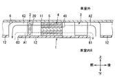
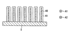
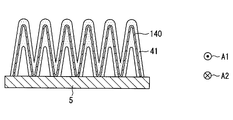
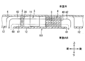
- FIG. 1 It is a schematic diagram showing a position where a humidification device concerning a 1st embodiment of this indication is carried in vehicles. It is sectional drawing which shows schematic structure of the humidification apparatus of 1st Embodiment. It is sectional drawing which shows the integrated cooling device and moisture absorbent material module which concern on 1st Embodiment. It is sectional drawing which shows the integrated cooling device and moisture absorbent material module which concern on 2nd Embodiment of this indication. It is sectional drawing which shows the integral heat sink and moisture absorbent which concern on 3rd Embodiment of this indication. It is sectional drawing which shows schematic structure of the humidification apparatus which concerns on 4th Embodiment of this indication.
- the disclosed humidifying device is a device that is mounted on an interior member in a vehicle interior, and is a device that uses the vehicle interior as a space to be humidified.
- a case where the present invention is applied to a vehicle as illustrated in FIG. 1 will be described as an example of a humidifier. Therefore, the humidifying device 1 mounted on the vehicle uses the vehicle interior R as a humidifying target space.
- the vehicle including the humidifying device 1 includes a vehicle air conditioner that adjusts the temperature of the passenger compartment R.
- the humidifier 1 is installed on the ceiling of the vehicle.
- the up and down arrows shown in FIGS. 1 and 2 indicate directions in a state where the humidifier 1 is mounted on a vehicle. Therefore, the upper side, the lower side, the front side, and the rear side are the vehicle upper side, the vehicle lower side, the vehicle front side, and the vehicle rear side, respectively.
- the humidifier 1 is configured by housing a blower 2, a heating device 3, a moisture absorbent module 4, a cooling device 5 and the like inside a casing 6 forming an outer shell thereof.
- the flow of air at the time of desorption is indicated by solid arrows in FIG.
- the humidifying device 1 is provided with a cooling device 5 and a moisture absorbent material module 4 on the upstream side and a heating device 3 on the downstream side in a direction A1 in which air flows when moisture is absorbed by the moisture absorbing element. Accordingly, the vehicle interior air introduced into the air passage 62 from the first opening 60 during moisture absorption releases moisture to the moisture absorbent 41 when passing through the moisture absorbent module 4 directly cooled by the cooling device 5, thereby heating the heating device. After being heated at 3, the air is blown out from the second opening 61 into the vehicle interior. The flow of air at the time of moisture absorption is indicated by broken-line arrows in FIG. In addition, at the time of moisture absorption, the air after releasing moisture to the moisture absorbent 41 may not be heated by the heating device 3.
- the hygroscopic material 41 is a hygroscopic part that desorbs moisture adsorbed to air and adsorbs moisture from the air.
- the blower 2 is installed at a position closer to the first opening 60 than other devices, but the installation position of the blower 2 is not limited to this position. Therefore, the air blower 2 can be installed at an arbitrary position in the air passage 62 on the back of the ceiling formed between the first opening 60 and the second opening 61.
- the blower 2 is, for example, an electric blower that rotationally drives the axial fan 20 with an electric motor.
- the blower 2 is a blower in which the operation rate, that is, the rotation speed and the amount of blown air are controlled by a control voltage output from the control device.
- the blower device 2 is configured to be able to switch the flow direction of the blown air to the opposite direction by switching the rotation direction of the electric motor by the control device.
- the control device rotates the electric motor in the forward direction
- the blown air flows as indicated by solid line arrows in FIG.
- the air in the passenger compartment is sucked into the air passage 62 from the second opening 61 and flows in the order of the heating device 3 and the moisture absorbent material module 4 to become humidified air and sits on the front seat in the passenger compartment from the first opening 60. It is blown out to the upper body side of the passenger.
- the control device reverses the electric motor, the blown air flows as indicated by the broken-line arrows in FIG.
- the air in the passenger compartment is sucked into the air passage 62 from the first opening 60, flows in the order of the moisture absorbent module 4 and the heating device 3, and becomes dehumidified air and blows out from the second opening 61 to the rear seat side of the passenger compartment. Is done.
- the casing 6 is formed in a box shape by resin or metal, and has an air passage 62 through which the blown air blown from the blower 2 is circulated.
- the casing 6 has a thin rectangular parallelepiped shape in which the thickness dimension in the vertical direction is approximately the same as the thickness dimension of the interior member 12 attached to the vehicle interior side of the vehicle top plate 11 and extends along the vehicle top plate 11. Is formed.
- the lower surface of the casing 6, that is, the surface on the vehicle interior side, is formed with at least two openings through which the blown air flows in and out between the vehicle interior R and the air passage 62.
- the first opening 60 disposed on the front side of the vehicle opens toward the upper half of the occupant seated in the front seat of the vehicle.
- the second opening 61 disposed on the vehicle rear side opens toward the rear seat side.
- the first opening 60 and the second opening 61 are provided with a net-like filter having a relatively low ventilation resistance, and foreign matter can be prevented from flowing into the air passage 62.
- the hygroscopic module 4 includes a plurality of metal plate-like members 40 carrying the hygroscopic material 41 stacked at intervals and a passage through which blown air passes between the plate-like members 40.
- the moisture absorbent module 4 is configured integrally with the cooling device 5. Therefore, the moisture in the air can be absorbed into the moisture absorbent 41 by cooling the moisture absorbent 41 with the cooling action of the cooling device 5.
- the contact area between the blown air and the hygroscopic material can be increased by arranging the plurality of plate-like members 40 carrying the hygroscopic material 41 in this manner.
- a hygroscopic material such as an organic polymer hygroscopic material, an inorganic material zero light, silica gel or the like is employed.
- the cooling device 5 functions as a cooling unit capable of cooling the air flowing through the air passage 62 and the hygroscopic material 41.
- a device that cools the hygroscopic material 41 provided on the surface of the plate member 40 by exchanging heat between the plate member 40 and a medium having a temperature lower than that of the plate member 40 can be used.
- a heat exchanger can be used for the cooling device 5.
- the low-temperature medium flowing inside the heat exchanger outside air, conditioned air, a refrigerant flowing through a refrigeration cycle used in an air conditioner, or the like can be used.
- a heat exchanger that uses outside air as a low temperature medium includes, for example, a heat sink attached to the vehicle top plate 11.
- the heat sink is a heat transfer member having a plurality of fins formed of a metal having excellent heat transfer properties, for example, aluminum or copper.
- the heat sink functions to transfer the temperature of outside air outside the passenger compartment to the air passage 62 through the vehicle top plate 11.
- the heat sink can exchange heat between the outside air outside the passenger compartment and the hygroscopic material 41. This heat sink cools the blown air by dissipating the heat of the blown air to the outside air by cooling the moisture absorbent 41 by allowing the cold air of the outside air to cool to the moisture absorbent 41 through the plate member 40.
- a cooling device is configured.
- the surface on the air passage 62 side or the surface exposed to the air passage 62 in the cooling device 5 is coupled to a plurality of plate-like members 40 erected at intervals so as to be capable of heat transfer.
- the plate-like member 40 is formed including a metal having a high thermal conductivity such as aluminum or copper.
- the plate-like member 40 is provided such that its surface is exposed to the air passage 62 in a posture along the air flow direction.
- a hygroscopic material 41 is provided on all or part of the surface of the plate-like member 40.
- the hygroscopic material 41 is preferably covered on the entire surface of the plate-like member 40.
- the heating device 3 is a heating unit that can heat the air flowing through the air passage 62.
- the heating device 3 can employ various methods as the heating method as long as it can heat the air.
- a device having a heating element that generates heat when energized, or a device that heats indoor air by exchanging heat between a medium and air that is hotter than indoor air can be used.
- the heating device 3 is, for example, a device having a nichrome wire heater, a PTC (Positive Temperature Coefficient) heater, a heat exchanger, or the like.
- a heating element such as hot water, a refrigerant, engine cooling water, or an electronic component that generates heat in the vehicle can be used as a medium having a temperature higher than that of air used in the heat exchanger.
- the control device is composed of a microcomputer including a CPU, a ROM, a RAM and the like and peripheral circuits thereof, and controls the operation of the blower 2 connected to the output side. Further, the control device may control a heating action or a cooling action by the heating device 3 or the cooling device 5.
- an inside air sensor as an inside air temperature detecting device for detecting the air temperature in the vehicle interior R
- an outside air sensor as an outside air temperature detecting device for detecting the outside temperature (outside air temperature) of the vehicle interior, and the like.
- the detection signals of these sensors are input.
- an operation switch for operating the humidifying device 10 is connected to the input side of the control device, and operation signals of these switches are input.
- this control device may be configured integrally with, for example, an air conditioning control device that controls the operation of each component of the vehicle air conditioning device. This control device may be separate from the air conditioning control device and may communicate information regarding the control state of the device to be controlled.
- the humidifier 1 operates when the operation switch is turned on by the operation of the occupant in a state where the temperature of the vehicle interior is adjusted by the vehicle air conditioner.
- the humidifier 1 is operated when the outside air temperature is relatively low and the vehicle interior R is easy to dry, such as in winter.
- the control device when the operation switch is turned on, the control device alternately switches between a state in which the electric motor of the blower 2 is normally rotated and a state in which the electric motor is reversed, for example, every predetermined time.
- the ventilation path through which the blown air flows as shown by the solid line arrow in FIG. 2 and the ventilation path through which the blown air flows as shown by the broken line arrow in FIG. 2 are switched every predetermined time.
- the control device causes the electric motor of the blower 2 to rotate forward, the air in the passenger compartment R whose temperature is adjusted to 25 ° C., for example, is sucked into the air passage 62 of the humidifying device 1 through the second opening 61.
- the blown air sucked into the air passage 62 is first heated when passing through the heating device 3.
- the control device operates the heating device 3 at a constant output so that the temperature of the blown air after passing through the heating device 3 is higher than the air temperature in the passenger compartment R by a predetermined temperature, for example, 5 ° C., or The output of the heating device 3 is controlled according to the temperature change of the air. Therefore, the temperature of the blown air after passing through the heating device 3 rises to about 30 ° C.
- the blown air after passing through the heating device 3 flows into the moisture absorbent module 4.
- the relative humidity of the blown air whose temperature has increased after passing through the heating device 3 is lower than the relative humidity of the air in the passenger compartment R. Therefore, by bringing the blown air whose relative humidity has decreased after passing through the heating device 3 into contact with the hygroscopic material 41, the moisture adsorbed on the hygroscopic material 41 is easily desorbed into the air. That is, the air whose relative humidity has been lowered by the heating device 3 is likely to contain moisture retained by the moisture absorbent material 41, and the air that has flowed out of the moisture absorbent material module 4 becomes humidified air that has been sufficiently humidified. This humidified air is blown out from the first opening 60 toward the occupant.
- the temperature of the air can be quickly raised. Further, since the relative humidity of the air can be lowered quickly due to the rapid increase in the air temperature, moisture desorption in the hygroscopic material module 4 is actively performed, and the air after flowing out of the hygroscopic material module 4 The relative humidity can be increased quickly.
- the air in the passenger compartment R whose temperature is adjusted to 25 ° C., for example, is sucked into the air passage 62 of the humidifier 1 through the first opening 60.
- the blown air sucked into the air passage 62 flows into the hygroscopic material module 4, it contacts the hygroscopic material 41 and the plate-like member 40 cooled by the cooling device 5.
- the hygroscopic material 41 is cooled, the moisture in the air is easily adsorbed to the hygroscopic material 41, and the moisture absorption speed can be improved.
- the blown air from which moisture has been released is heated when passing through the heating device 3, and is blown out through the second opening 61 to the rear seat side and the lower part of the passenger compartment, not facing the upper body of the occupant.
- the moisture absorbing material 41 is cooled by the cooling device 5, whereby the moisture absorption rate for absorbing moisture from the air can be increased. For this reason, water
- the humidifier 1 is a device that switches between absorption and release of moisture with respect to air by changing the air flow direction in the same air passage 62 in the opposite direction.
- the humidifying device 1 includes a heating unit, a cooling unit, a moisture absorption unit that is provided in the air passage 62 and desorbs moisture adsorbed to the air and adsorbs moisture from the air, and is desorbed and adsorbed in the air passage 62. And a blower that generates air flow directions that are opposite to each other.
- the moisture absorption part and the cooling part are integrally formed.
- the hygroscopic part can be directly cooled by integrally forming the hygroscopic part and the cooling part. According to this, compared with the case where the hygroscopic part is cooled via air, the temperature of the hygroscopic part can be lowered quickly and can be kept low, so that moisture absorption into the hygroscopic part can be performed quickly. Can contribute. Furthermore, by integrally forming the moisture absorption part and the cooling part installed in the air passage 62, it is possible to contribute to shortening the air passage 62 provided in the humidifying device 1. Therefore, it is possible to provide the humidifying device 1 that improves the mode switching response to dehumidification and reduces the size of the device in the air flow direction.
- the moisture absorption part in the humidification apparatus 1 is provided on the surface of the several plate-shaped member 40 provided integrally with the cooling part.
- a device capable of directly cooling the hygroscopic material 41 with a simple configuration in which a plurality of plate-like members 40 are integrally formed and coupled to the cooling device 5 that can be controlled to a temperature lower than the ambient temperature. Can be provided. Therefore, this configuration can contribute to the miniaturization of the humidifier 1 and the improvement of the moisture absorption speed.
- the second embodiment is different from the first embodiment in the plurality of plate-like members 140 provided with the hygroscopic material 41.
- the hygroscopic material 41 is stored on the surfaces of a plurality of plate-like members 140 provided integrally with the cooling device 5.
- the plate-like member 140 is a corrugated plate bent in a wave shape.
- the hygroscopic material module is configured by stacking a plurality of corrugated plates carrying the hygroscopic material 41 at intervals.
- the moisture absorption part of 2nd Embodiment is provided in the surface of the several plate-shaped member 140 provided integrally with the cooling part.
- a device capable of directly cooling the hygroscopic material 41 with a simple configuration in which a plurality of plate-like members 140 are integrally formed and coupled to the cooling device 5 that can be controlled to a temperature lower than the ambient temperature. Can be provided.
- This configuration can contribute to the miniaturization of the humidifier 1 and the improvement of the moisture absorption speed.
- the outer fin in the evaporator in which the refrigerant flows and evaporates can be used as the plate-like member 40. That is, the humidifier of the second embodiment can be configured by covering the surface of the outer fin that contacts the evaporator tube with the hygroscopic material 41.
- the third embodiment is different from the first embodiment in that the heat sink 240 provided with the hygroscopic material 41 is cooled by the cooling device 5.
- the heat sink 240 includes a base portion that is provided integrally with the cooling device 5 in a state where the heat sink 240 is in contact with the cooling device 5 so as to be capable of heat transfer, and a plurality of plate-like portions that are erected so as to extend from the base portion.
- the heat sink 240 is a heat conductive member having a plurality of plate-like portions formed of a metal having excellent heat conductivity, for example, aluminum or copper.
- the heat sink 240 functions to transfer heat from the hygroscopic material 41 or the plate-like portion to the cooling device 5.
- the heat sink 240 can exchange heat between the air flowing through the air passage 62 and the hygroscopic material 41 using the cooling capacity of the cooling device 5.
- the outer fin in the evaporator in which the refrigerant evaporates can be used as the heat sink 240. That is, the humidifier of the third embodiment can be configured by covering the surface of the outer fin that contacts the evaporator tube with the moisture absorbent 41.
- the humidifying device 101 according to the fourth embodiment is different from the first embodiment in that a hygroscopic part and a heating part are integrally formed.
- the heating device 3 and the moisture absorbent module 4 are arranged on the upstream side, and the cooling device 5 is arranged on the downstream side in the direction A2 in which air flows when moisture is desorbed from the moisture absorbing element. Is installed. Therefore, the vehicle interior air introduced from the second opening 61 at the time of detachment is cooled by the cooling device 5 after moisture is added when passing through the moisture absorbent material module 4 heated by the heating device 3. From the first opening 60 into the passenger compartment.
- the cooling device 5 is arranged on the upstream side, and the moisture absorbent material module 4 and the heating device 3 are arranged on the downstream side in the direction A1 in which air flows when moisture is absorbed by the moisture absorbing elements. Therefore, after the vehicle interior air introduced from the first opening 60 during moisture absorption is cooled by the cooling device 5, the moisture is released to the moisture absorbent 41 when passing through the moisture absorbent module 4 heated by the heating device 3. In the dehumidified state, the air is blown out from the second opening 61 into the vehicle compartment.
- the surface of the heating device 3 on the side of the air passage 62 or the surface exposed to the air passage 62 is coupled to a plurality of plate-like members 40 erected at intervals so as to be capable of heat transfer. .
- the control device causes the electric motor of the blower 2 to rotate forward, the air in the vehicle interior R is sucked into the air passage 62 of the humidifier 101 through the second opening 61.
- the blown air sucked into the air passage 62 flows into the moisture absorbent material module 4, it contacts the moisture absorbent material 41 and the plate-like member 40 heated by the heating device 3.
- the hygroscopic material 41 is heated, the moisture adsorbed on the hygroscopic material 41 is easily detached from the air in contact with the hygroscopic material 41. That is, the heated hygroscopic material 41 easily releases the retained moisture, and the air after flowing out of the hygroscopic material module 4 becomes humidified air that has been sufficiently humidified.
- the humidified air is cooled by the cooling device 5 and then blown out from the first opening 60 toward the occupant.
- the air in the vehicle interior R is sucked into the air passage 62 of the humidifier 1 through the first opening 60.
- the blown air sucked into the air passage 62 is cooled by the cooling device 5 and decreases in temperature, so that the relative humidity is high.
- the blown air whose relative humidity is high comes into contact with the hygroscopic material 41 when flowing into the hygroscopic material module 4.
- Moisture in the blown air whose relative humidity has increased is likely to be adsorbed by the moisture absorbent 41, and the moisture absorption rate can be improved.
- the blown air from which moisture has been released is heated when passing through the heating device 3, and blown out through the second opening 61 to the rear seat side or below the passenger compartment.
- the moisture absorption rate can be increased by cooling the air with the cooling device 5 and then allowing the moisture absorbent material 41 to absorb moisture.
- the humidifier 101 of 2nd Embodiment is provided with the moisture absorption part and heating part which were formed integrally. According to this configuration, the hygroscopic part can be directly heated by integrally forming the hygroscopic part and the heating part. According to this, since the temperature of the hygroscopic part can be rapidly increased as compared with the case where the hygroscopic part is heated via air, the desorption rate of moisture from the hygroscopic part can be improved. Furthermore, by integrally forming the moisture absorption part and the heating part installed in the air passage 62, it is possible to contribute to shortening the air passage 62 provided in the humidifying device 101. Therefore, it is possible to provide the humidifier 101 that improves the mode switching response to humidification and reduces the size of the device in the air flow direction.
- the moisture absorption part in the humidification apparatus 101 is provided on the surface of the several plate-shaped member 40 provided integrally with the heating part.
- a device capable of directly heating the hygroscopic material 41 with a simple configuration in which a plurality of plate-like members 40 are integrally formed and coupled to the heating device 3 that can be controlled to be higher than the ambient temperature. Can be provided. Therefore, this configuration can contribute to the miniaturization of the humidifier 101 and the improvement of the desorption speed.
- the fifth embodiment is different from the fourth embodiment in the plurality of plate-like members 140 provided with the hygroscopic material 41.
- the hygroscopic material 41 is carried on the surfaces of a plurality of plate-like members 140 provided integrally with the heating device 3.
- the outer fin in the evaporator in which the refrigerant flows and evaporates can be used as the plate-like member 40. That is, the humidifier of the fifth embodiment can be configured by covering the surface of the outer fin that contacts the evaporator tube with the moisture absorbent 41.
- the sixth embodiment is different from the fourth embodiment in that a hygroscopic material 41 is provided on the surface of a plate-like heat generating portion that generates heat in the heating device 103.
- the hygroscopic material 41 is carried on the surface of the plate-like heat generating portion in the heating device 103.
- the heat generating portion is formed so that the cross-sectional shape is a waveform.
- the heat generating portion can be formed by bending a plate material in a zigzag manner. It is preferable that the hygroscopic material 41 is covered on the entire surface of the plate-like heat generating portion.
- the surface area of the hygroscopic material 41 can be set large by providing the hygroscopic material 41 integrally on the surface of the plate-like heat generating portion. Therefore, since the hygroscopic material 41 can be widely provided on the plate-like surface, a humidifier with an increased moisture absorption amount and a desorbed moisture amount can be provided.
- FIGS. 10 and 11 A seventh embodiment will be described with reference to FIGS. 10 and 11.
- the components denoted by the same reference numerals as those in the drawings according to the first embodiment and the fourth embodiment and the configurations not described are the same as those in the above-described embodiment, and have the same operational effects. .
- the seventh embodiment only parts different from the above-described embodiment will be described.
- the seventh embodiment is different from the fourth embodiment in that a hygroscopic material 41 is provided on the surface of a coil-shaped heat generating portion that itself generates heat in the heating device 203.
- the hygroscopic material 41 is carried on the surface of the coil-shaped heat generating part in the heating device 203.
- the heat generating part has an outer shape in which a wire having a circular cross-sectional shape is wound in a coil shape.
- the heat generating portion is a linear heating element, and can be formed by winding a wire such as a nichrome wire in a coil shape.
- the hygroscopic material 41 is preferably covered on the entire surface of the wire forming the coil shape.
- the surface area of the hygroscopic material 41 can be set large. Therefore, the humidification apparatus which can increase the moisture absorption amount of water
- the eighth embodiment is different from the fourth embodiment in that the hygroscopic material 41 is provided on the surface of the plate-like heat generating portion that itself generates heat, and the heating device 303 and the hygroscopic material 41 are integrally formed.
- the hygroscopic material 41 is carried on the surface of the plate-like heat generating part of the heating device 303.
- the heat generating part is formed so that the cross-sectional shape is an elongated rectangular shape.
- a planar heating element such as a PTC planar heater or a planar carbon heater can be used for the heat generating portion.
- the hygroscopic material 41 is covered on the entire surface of the planar body constituting the heat generating portion.
- the heating device 303 may be configured by stacking a plurality of plate-like heat generating portions in a posture in which the surfaces are opposed to each other with an interval.
- the surface area of the hygroscopic material 41 can be set large by providing the hygroscopic material 41 integrally on the surface of the plate-like heat generating portion. Therefore, since the hygroscopic material 41 can be widely installed on the plate-shaped surface, it is possible to provide a humidifier that increases the moisture absorption amount and the moisture amount to be desorbed.
- a plurality of small passages through which air flows can be formed in the air passage 62 by forming a heating device 303 by stacking a plurality of plate-like heat generating portions with the surfaces facing each other with a gap therebetween, and thus a small passage can be formed.
- An air flow in contact with the hygroscopic material 41 can be formed for each passage. Therefore, since the surface area of the hygroscopic material 41 can be set large for each small passage, it is possible to provide a humidifier with an increased amount of moisture absorption and moisture desorption as a whole air flow.
- FIGS. 13 and 14 A ninth embodiment will be described with reference to FIGS. 13 and 14.
- components denoted by the same reference numerals as those in the drawing according to the first embodiment and configurations not described are the same as those in the first embodiment and have the same effects.
- only parts different from the first embodiment will be described.
- the humidifying device 201 of the ninth embodiment is different from the humidifying device 1 of the first embodiment in that a Peltier module 7 having both functions of a heating device and a cooling device is provided integrally with the moisture absorbent material module 4.
- the Peltier module 7 has a Peltier element. When the control device changes the direction of the current flowing in the Peltier element, one side surface or the other side surface of the Peltier element absorbs heat or generates heat.
- the Peltier element has one side plate portion located on the air passage 62 side and the other side plate portion located outside the passenger compartment.
- the Peltier module 7 is provided so as to be integrated with the moisture absorbent material module 4 on the surface on the air passage 62 side corresponding to the one side plate portion of the Peltier element. As shown in FIG. 14, the surface on the air passage 62 side of the Peltier module 7 is coupled to a plurality of plate-like members 40 erected at intervals in the same manner as in FIG. 3.
- a Peltier element is an element that uses the Peltier effect in which heat is transferred from one metal to the other when a current is passed through a joint between two types of metal, and it does not have a movable part.
- the Peltier element for example, a plurality of P-type semiconductors and N-type semiconductors are arranged between two types of metal plates, one metal plate forms an NP junction, and the other metal plate forms a PN junction. It is a configured element.
- a heat absorption phenomenon occurs in the metal plate corresponding to the N ⁇ P junction, and a heat dissipation phenomenon occurs in the metal plate corresponding to the P ⁇ N junction.
- each of the one side plate portion and the other side plate portion of the Peltier element becomes a heat absorbing portion that absorbs heat when bridging so that current flows from the N-type semiconductor to the P-type semiconductor, and current is transferred from the P-type semiconductor to the N-type semiconductor. When bridging so as to flow, it becomes a heat radiating part that generates heat.
- the Peltier module 7 functions as a cooling unit.
- the air in the vehicle compartment sucked from the first opening 60 by the blower 2 flows in the direction A1 and is absorbed and cooled when passing around the plate-like member 40.
- the heat transferred from the air to the plate-like member 40 is transmitted to the other side plate portion of the Peltier element and is discharged outside the passenger compartment.
- the air flowing through the air passage 62 is blown out from the second opening 61 into the vehicle interior as dehumidified air after moisture is adsorbed by the moisture absorbent 41.
- the Peltier module 7 functions as a heating unit.
- the air in the vehicle interior sucked from the second opening 61 by the blower 2 flows in the direction A2 and is heated by heat dissipation when passing around the plate-like member 40.
- the air flowing through the air passage 62 is blown out from the first opening 60 to the vehicle interior as humidified air by the moisture desorbed from the moisture absorbent material 41.
- the Peltier module 7 is a device having a heat absorbing part that absorbs heat from air and a heat radiating part that radiates heat to the air according to the energized state.
- the humidifier 201 is a device that changes the air flow direction in the same air passage 62 in the opposite direction and switches between absorption and release of moisture with respect to the air.
- the humidifying device 201 includes a heating unit, a cooling unit, a moisture absorption unit that is provided in the air passage 62 and desorbs moisture adsorbed to the air and adsorbs moisture from the air. And a blower that generates air flow directions that are opposite to each other.
- the hygroscopic part, the cooling part and the heating part are integrally formed.
- the hygroscopic part can be directly heated or cooled by integrally forming the hygroscopic part, the cooling part, and the heating part. According to this, compared with the case where the moisture absorption part is cooled via air, the temperature of the moisture absorption part can be quickly reduced and kept low, so that moisture absorption into the moisture absorption part can be performed quickly. it can. Moreover, since the temperature of a moisture absorption part can be raised rapidly compared with the case where a moisture absorption part is heated via air, the desorption rate of the water
- the humidifier 201 improves the mode switching response to humidification and dehumidification and reduces the size of the device in the air flow direction.
- the hygroscopic material 41 is provided on the surfaces of the plurality of plate-like members 40 provided integrally with the Peltier module 7.
- the humidifying device 201 in which the hygroscopic part, the heating part, and the cooling part are integrally formed. Therefore, the hygroscopic part can be directly heated and cooled. According to this, the desorption of moisture from the hygroscopic material 41 and the absorption of moisture into the hygroscopic material 41 can be performed more quickly than when the hygroscopic part is heated and cooled via air.
- the humidifying device 201 includes the Peltier module 7 that can switch the function of the cooling unit and the function of the heating unit in accordance with the direction of the current, the size of the device in the air flow direction can be reduced.
- the humidifying device of the tenth embodiment is different from the humidifying device 1 of the first embodiment in that the heating device 3 and the cooling device 5 are integrally provided on the heat exchange member 340 on which the moisture absorbent material 41 is provided. Is different.
- the humidifier according to the tenth embodiment includes a heat exchange member 340 that is provided in the air passage 62 and exchanges heat with the air flowing through the air passage 62.
- the heat exchange member 340 is formed of a material having thermal conductivity such as aluminum or copper, and is a box-like member having an internal passage through which air flows.
- the heat exchange member 340 has an internal passage partitioned into a plurality of parts.
- the heating device 3 is provided so as to heat one side portion of the heat exchange member 340 in the air flow direction.
- the cooling device 5 is provided so as to cool the other side of the heat exchange member 340 in the air flow direction.
- the hygroscopic material 41 is provided on the surface in contact with air in the intermediate portion 104 that is located between the one side portion and the other side portion and occupies a predetermined range.
- the intermediate part 104 carries the moisture absorbing material 41 on the wall surface forming each internal passage.
- the control device causes the electric motor of the blower 2 to rotate forward, the air in the vehicle interior R is sucked into the air passage 62 via the second opening 61.
- the blown air sucked into the air passage 62 is heated when it passes through the internal passage on one side of the heat exchange member 340 heated by the heating device 3. At this time, the temperature of the blown air after passing through one side of the heat exchange member 340 rises higher than the air temperature in the passenger compartment R.
- the relative humidity of the blown air is lower than the relative humidity of the air in the passenger compartment R. Therefore, when the blown air whose relative humidity has decreased is brought into contact with the hygroscopic material 41 carried on the intermediate portion 104, the moisture adsorbed on the hygroscopic material 41 is easily desorbed into the air. That is, the air whose relative humidity has been lowered by the heating device 3 tends to include moisture retained by the moisture absorbent 41, and the air that has flowed out of the intermediate portion 104 becomes humidified air that has been sufficiently humidified.
- the humidified air is further cooled when passing through the internal passage on the other side of the heat exchange member 340 cooled by the cooling device 5.
- the blown air after passing through the other side portion of the heat exchange member 340 is humidified air, becomes cool air having a lowered temperature, and is blown out from the first opening 60 toward the occupant.
- the heating output by the heating device 3 and the cooling output by the cooling device 5 are preferably dominated by the heating output in order to heat the hygroscopic material 41.
- the blown air after passing through the other side portion of the heat exchange member 340 flows into the intermediate portion 104. At this time, the blown air contacts the hygroscopic material 41 cooled by the cooling device 5. Since the moisture absorbent 41 is cooled, the moisture in the air is easily adsorbed to the moisture absorbent 41, and the moisture absorption speed can be improved. Furthermore, the blown air from which moisture has been released is heated when passing through one side of the heat exchange member 340 and blown out through the second opening 61 to the rear seat side or below the vehicle interior.
- the moisture absorbing material 41 in the intermediate portion 104 is cooled by the cooling device 5, so that the moisture absorption rate for absorbing moisture from the air can be increased. For this reason, the water
- the heating output by the heating device 3 and the cooling output by the cooling device 5 are preferably dominated by the cooling output in order to cool the hygroscopic material 41.
- the hygroscopic part, the cooling part, and the heating part are integrally formed.
- the hygroscopic part can be directly heated or cooled.
- the temperature of the hygroscopic part can be quickly lowered and can be kept low, so that moisture can be quickly absorbed into the hygroscopic part.
- the temperature of the moisture absorption part can be raised rapidly, the desorption rate of the water
- the disclosure of this specification is not limited to the illustrated embodiments.
- the disclosure encompasses the illustrated embodiments and variations by those skilled in the art based thereon.
- the disclosure is not limited to the combination of components and elements shown in the embodiments, and various modifications can be made.
- the disclosure can be implemented in various combinations.
- the disclosure may have additional parts that can be added to the embodiments.
- the disclosure includes those in which the components and elements of the embodiment are omitted.
- the disclosure encompasses parts, element replacements, or combinations between one embodiment and another.
- the technical scope disclosed is not limited to the description of the embodiments.
- the configuration of the hygroscopic material module is not limited to the configuration described in the above embodiment.
- the humidifier is installed on the back side of the ceiling material of the vehicle, but is not limited to this installation location.
- the humidifier 1 can be mounted on the back side of an interior member or the like that communicates with an instrument panel, a door trim, a steering column, a trunk room, and the like.
- the first opening 60 is located on the front seat side so that the humidified air is supplied to the front seat side of the vehicle, and the second opening is provided so that the dehumidified air is supplied to the rear seat side of the vehicle.
- the part 61 is located on the rear seat side, it is not limited to this positional relationship.
- the first opening 60 is disposed so as to open toward the upper body side of the occupant seated in the front seat of the vehicle, and the second opening 61 is opened toward the rear seat.
- positioning of each opening part is not limited to this.
Landscapes
- Engineering & Computer Science (AREA)
- Mechanical Engineering (AREA)
- Chemical & Material Sciences (AREA)
- Combustion & Propulsion (AREA)
- General Engineering & Computer Science (AREA)
- Air-Conditioning For Vehicles (AREA)
- Central Air Conditioning (AREA)
- Air Humidification (AREA)
Abstract
加湿装置(1)は、同一の空気通路(62)における空気流れ方向を逆向きに変化させて、空気に対する水分の吸収と放出とを切り換える装置である。加湿装置は、加熱装置(3)、冷却装置(5)、吸湿材(41)、および送風装置(2)を備える。吸湿材は、空気通路(62)に設けられ、加熱装置による加熱作用によって加熱された空気に対して吸着されている水分を脱離し、冷却装置による冷却作用によって冷却された空気から水分を吸着する。送風装置は、空気通路において脱離時と吸着時とで互いに逆向きの空気流れ方向を発生させる。吸湿材と、加熱装置および冷却装置の少なくとも一つとは一体に形成されている。これにより、加湿または除湿へのモード切換え応答性の向上と空気流れ方向の装置寸法の小型化を図ることができる。
Description
本出願は、当該開示内容が参照によって本出願に組み込まれた、2016年1月29日に出願された日本特許出願2016-015184を基にしている。
本開示は、車室内に対して加湿空気を提供する加湿装置に関する。
特許文献1は、車室内の乗員に対して加湿された空気を供給する車両用除加湿装置の一形態を開示している。特許文献1に記載の装置は、吸着時には車室内の空気をヒートシンクの周囲を通過させることによって冷却した後に吸湿材モジュールへ流入させる。一方、脱離時には、車室内の空気を加熱または冷却することなく吸湿材モジュールへ流入させて加湿し、さらに加湿された空気をヒートシンクの周囲を通過させることによって冷却して車室内へ吹き出す。
特許文献1の装置は、吸着時に空気を強制的に冷却するためのヒートシンクを備えるが、脱離時には空気を強制的に加熱できる加熱装置を備えていない。例えば、特許文献1の装置は、加湿モードに切り換わる際に加熱遅れが生じ、性能を高めるためにモード切換えの応答性の点で向上できる余地がある。また、特許文献1の装置は、ヒートシンクによって冷却した空気を吸湿材モジュールに供給するため、ヒートシンクと吸湿材モジュールとを空気流れ方向に間隔をあけて並べる配置関係を採用している。したがって、特許文献1の装置は、空気流れ方向の装置寸法を短くできる余地がある。
このような点に鑑み、本開示の目的は、加湿または除湿へのモード切換え応答性の向上と空気流れ方向の装置寸法の小型化とを図る加湿装置を提供することである。
本開示の一態様によると、加湿装置は、同一の空気通路における空気流れ方向を逆向きに変化させて、空気に対する水分の吸収と放出とを切り換える加湿装置である。加湿装置は、熱を発生する加熱部と、吸熱する冷却部と、空気通路に設けられ、空気に対して吸着されている水分を脱離し空気から水分を吸着する吸湿部と、空気通路において脱離時と吸着時とで互いに逆向きの空気流れ方向を発生させる送風部と、を備える。吸湿部と、加熱部および冷却部の少なくとも一つとを一体に形成した加湿装置である。
この加湿装置によれば、吸湿部および加熱部、吸湿部および冷却部、吸湿部、加熱部および冷却部、のいずれかを一体に形成する構成により、吸湿部を直接、加熱または冷却することができる。これによれば、空気を介して吸湿部を加熱または冷却する場合に比べて吸湿部からの水分の脱離や吸湿部への水分の吸収を迅速に行うことに寄与する。さらに、空気通路に設置される吸湿部と加熱部または冷却部とを一体に形成することにより、加湿装置が備える空気通路を短く構成することができる。したがって、加湿または除湿へのモード切換え応答性の向上と空気流れ方向の装置寸法の小型化とを図る加湿装置を提供できる。
以下に、図面を参照しながら本開示を実施するための複数の形態を説明する。各形態において先行する形態で説明した事項に対応する部分には同一の参照符号を付して重複する説明を省略する場合がある。各形態において構成の一部のみを説明している場合は、構成の他の部分については先行して説明した他の形態を適用することができる。各実施形態で具体的に組合せが可能であることを明示している部分同士の組合せばかりではなく、特に組合せに支障が生じなければ、明示してなくとも実施形態同士を部分的に組み合せることも可能である。
(第1実施形態)
開示する加湿装置は、車室内の内装部材に装着される装置であり、車室内を加湿対象空間とする装置である。以下の各実施形態では、加湿装置の一例として、図1に図示するように車両に適用した場合を説明する。したがって、車両に搭載される加湿装置1は、車室内Rを加湿対象空間とする。加湿装置1を備える車両は、車室内Rの温度調整を行う車両用空調装置を備える。
開示する加湿装置は、車室内の内装部材に装着される装置であり、車室内を加湿対象空間とする装置である。以下の各実施形態では、加湿装置の一例として、図1に図示するように車両に適用した場合を説明する。したがって、車両に搭載される加湿装置1は、車室内Rを加湿対象空間とする。加湿装置1を備える車両は、車室内Rの温度調整を行う車両用空調装置を備える。
図1及び図2に示すように、加湿装置1は、車両の天井に設置される。図1及び図2に記載した上下前後の各矢印は、加湿装置1を車両に搭載した状態における各方向を示している。したがって、上側、下側、前側、後側は、それぞれ、車両上方、車両下方、車両前方、車両後方である。加湿装置1は、その外殻を形成するケーシング6の内部に、送風装置2、加熱装置3、吸湿材モジュール4、冷却装置5等を収容して構成されている。
図2に示すように、加湿装置1においては、吸湿素子から水分が脱離する脱離時に空気が流れる方向A2について、上流側に加熱装置3、下流側に吸湿材モジュール4および冷却装置5が並ぶように設置されている。したがって、脱離時に、第2開口部61から導入された車室内空気は、加熱装置3で加熱されてから、吸湿材モジュール4を通過して水分が加えられた後、第1開口部60から車室内へ吹き出される。この脱離時の空気の流れは、図2において実線の矢印で示されている。
加湿装置1には、吸湿素子に水分が吸着される吸湿時に空気が流れる方向A1に、上流側に冷却装置5および吸湿材モジュール4、下流側に加熱装置3が並ぶように設置されている。したがって、吸湿時に第1開口部60から空気通路62に導入された車室内空気は、冷却装置5によって直接冷却された吸湿材モジュール4を通過するときに吸湿材41に水分を放出し、加熱装置3で加熱された後、第2開口部61から車室内へ吹き出される。この吸湿時の空気の流れは、図2において破線の矢印で示されている。また、吸湿時には、吸湿材41へ水分を放出した後の空気を加熱装置3によって加熱しないようにしてもよい。吸湿材41は、空気に対して吸着されている水分を脱離し空気から水分を吸着する吸湿部である。
送風装置2は、図2に示す例では、他の装置よりも第1開口部60に近い位置に設置されているが、送風装置2の設置位置は、この位置に限定されない。したがって、送風装置2は、第1開口部60と第2開口部61との間に形成される天井裏の空気通路62において、任意の位置に設置することができる。
送風装置2は、例えば、軸流のファン20を電動モータにて回転駆動する電動送風機である。送風装置2は、制御装置から出力される制御電圧によって稼働率、すなわち回転数や送風空気量が制御される送風装置である。さらに、送風装置2は、制御装置によって電動モータの回転方向が切り替えられることで送風空気の流れ方向を相反する向きに切り替えることができるように構成されている。
例えば、制御装置が電動モータを正転させると、送風空気は、図2の実線矢印に示すように流れる。車室内の空気は、第2開口部61から空気通路62へ吸い込まれ、加熱装置3、吸湿材モジュール4の順に流れ、加湿空気となって第1開口部60から車室内の前席に着座している乗員の上半身側へ吹き出される。一方、制御装置が電動モータを反転させると、送風空気は、図2の破線矢印に示すように流れる。車室内の空気は、第1開口部60から空気通路62へ吸い込まれ、吸湿材モジュール4、加熱装置3の順に流れ、除湿空気となって第2開口部61から車室内の後部座席側へ吹き出される。
ケーシング6は、樹脂または金属によって箱状に形成され、内部に送風装置2から送風された送風空気を流通させる空気通路62を形成している。ケーシング6は、上下方向の厚み寸法が車両天板11の車室内側に取り付けられた内装部材12の厚み寸法と同程度となっているとともに、車両天板11に沿って広がる薄形の直方体状に形成されている。
ケーシング6の下面、すなわち車室内側の面には、車室内Rと空気通路62との間で送風空気を流入出させる少なくとも2つの開口部が形成されている。これらの開口部のうち、車両前方側に配置された第1開口部60は、車両前席に着座している乗員の上半身に向かって開口している。車両後方側に配置された第2開口部61は、後部座席側に向かって開口している。例えば、第1開口部60、第2開口部61には、通風抵抗の比較的小さい網状のフィルタが配置され、空気通路62に異物が流入してしまうことを抑制することができる。
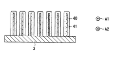
吸湿材モジュール4は、吸湿材41を担持させた複数の金属製の板状部材40を間隔をあけて積層配置し、板状部材40の間に送風空気を通過させる通路を備えている。吸湿材モジュール4は冷却装置5と一体に構成されている。したがって、冷却装置5の冷却作用によって吸湿材41を冷却することで、空気中の水分を吸湿材41へ吸湿することができる。この実施形態の吸湿材モジュール4では、このように吸湿材41を担持させた複数の板状部材40を積層配置することで、送風空気と吸湿材との接触面積を増加させることができる。吸湿材モジュール4では、吸湿材41として、有機系材料の高分子吸湿材、無機系材料のゼロライト、シリカゲル等の吸湿材料を採用する。
冷却装置5は、空気通路62を流通する空気や吸湿材41を冷却可能な冷却部として機能する。冷却装置5には、板状部材40よりも低温の媒体と板状部材40とを熱交換することによって、板状部材40の表面に設けられる吸湿材41を冷却する装置を用いることができる。例えば冷却装置5には、熱交換器を用いることができる。熱交換器の内部を流れる低温の媒体には、外気、空調空気、空調装置に用いられる冷凍サイクルを流れる冷媒等を採用することができる。
低温の媒体として外気を用いる熱交換器には、例えば、車両天板11に取り付けられるヒートシンクがある。ヒートシンクは、伝熱性に優れる金属、例えば、アルミニウム、銅で形成された複数のフィンを有する伝熱部材である。ヒートシンクは、車室外の外気の温度を車両天板11を通じて空気通路62に伝熱する機能を果たす。ヒートシンクは、車室外の外気と吸湿材41とを熱交換させることができる。このヒートシンクは、外気の有する冷熱を板状部材40を通じて吸湿材41に放冷することによって吸湿材41を冷却する冷却装置、または、送風空気の有する熱を外気に放熱させることによって送風空気を冷却する冷却装置を構成する。
図3に図示するように、冷却装置5における空気通路62側の面または空気通路62に露出する面は、間隔をあけて立設する複数の板状部材40と熱移動可能に結合されている。この板状部材40は、アルミニウム、銅など、熱伝導率の高い金属を含んで形成される。板状部材40は、その表面が空気流れ方向に沿う姿勢で空気通路62に露出するように設けられる。板状部材40の表面の全部または一部には、吸湿材41が設けられている。吸湿材41は、板状部材40の表面全体に被覆されていることが好ましい。
加熱装置3は、空気通路62を流通する空気を加熱可能な加熱部である。加熱装置3は、空気を加熱可能な構成であれば、その加熱方法として各種の方法を採用できる。加熱装置3には、通電によって発熱する発熱体を有する装置、室内の空気よりも高温の媒体と空気とを熱交換することによって室内空気を加熱する装置を用いることができる。加熱装置3は、例えば、ニクロム線ヒータ、PTC(Positive Temperature Coefficient)ヒータを有する装置、熱交換器等である。熱交換器に用いる空気よりも高温の媒体には、温水、冷媒、エンジン冷却水、車両において発熱する電子部品等の発熱体を採用することができる。
制御装置は、CPU、ROM及びRAM等を含むマイクロコンピュータとその周辺回路から構成されており、その出力側に接続された送風装置2の作動を制御する。また、制御装置は、加熱装置3や冷却装置5による加熱作用や冷却作用を制御するものであってもよい。
制御装置の入力側には、車室内Rの空気温度を検出する内気温検出装置としての内気センサ、車室外温度(外気温)を検出する外気温検出装置としての外気センサ等が接続されており、これらのセンサの検出信号が入力される。さらに、制御装置の入力側には、加湿装置10を作動させる作動スイッチ等が接続されており、これらのスイッチの操作信号が入力される。また、この制御装置は、例えば、車両用空調装置の各構成機器の作動を制御する空調用制御装置等と一体的に構成されるものでもよい。この制御装置は、空調用制御装置と別体で、制御対象とする装置の制御状態に関する情報を互いに通信するものであってもよい。
次に加湿装置1の作動について一例を説明する。加湿装置1は、例えば、車室内が車両用空調装置によって温度調整された状態で、乗員の操作によって作動スイッチがONされると作動する。
例えば、加湿装置1は、冬季のように比較的外気温が低く、車室内Rが乾燥しやすいときに作動させる。加湿装置1では、作動スイッチが投入されると、制御装置が送風装置2の電動モータを正転させる状態と反転させる状態とを、例えば所定時間毎に交互に切り替える。これにより、送風空気が図2の実線矢印に示すように流れる通風経路と、図2の破線矢印に示すように流れる通風経路とが所定時間毎に切り替えられることになる。
制御装置が送風装置2の電動モータを正転させると、例えば25℃に温度調整されている車室内Rの空気が、第2開口部61を介して加湿装置1の空気通路62へ吸い込まれる。空気通路62に吸い込まれた送風空気は、まず加熱装置3を通過するときに加熱される。
この際、加熱装置3を通過後の送風空気の温度が車室内Rの空気温度よりも所定温度、例えば、5℃分高くなるように、制御装置が加熱装置3を一定出力で作動させる、もしくは空気の温度変化に応じて加熱装置3の出力を制御する。したがって、加熱装置3を通過後の送風空気の温度が30℃程度に上昇する。
加熱装置3を通過後の送風空気は、吸湿材モジュール4に流入する。この際、加熱装置3を通過後の温度上昇した送風空気の相対湿度は、車室内Rの空気の相対湿度よりも低下している。したがって、加熱装置3を通過後の、相対湿度が下がった送風空気を吸湿材41に接触させることで、吸湿材41に吸着している水分が空気に脱離しやすい状況となる。つまり、加熱装置3によって相対湿度が下げられた空気は、吸湿材41が保持している水分を含みやすく、吸湿材モジュール4を流出後の空気は、十分に加湿された加湿空気となる。この加湿空気は、第1開口部60から乗員に向けて吹き出される。
この脱離時には、吸湿材モジュール4に供給する前の空気を加熱装置3で加熱するため、当該空気を迅速に温度上昇させることができる。さらに、空気温度が迅速に上昇したことにより、空気の相対湿度を迅速に下げることができるため、吸湿材モジュール4での水分脱離が活発に行われ、吸湿材モジュール4を流出後の空気の相対湿度を迅速に高めることができる。
制御装置が送風装置2の電動モータを反転させると、例えば25℃に温度調整されている車室内Rの空気が、第1開口部60を介して、加湿装置1の空気通路62に吸い込まれる。空気通路62に吸い込まれた送風空気は、吸湿材モジュール4に流入する際に、冷却装置5によって冷却された吸湿材41や板状部材40に接触する。吸湿材41が冷却されることにより、空気の水分が吸湿材41に吸着しやすい状況となり、吸湿速度を向上することができる。さらに、水分を放出した送風空気は、加熱装置3を通過する際に加熱され、第2開口部61を介して乗員の上半身に向いていない、後部座席側や車室内の下方に吹き出される。
この吸湿時には、冷却装置5によって吸湿材41を冷却することで、空気から水分を吸湿する吸湿速度を高めることができる。このため、吸湿材モジュール4での水分吸着が活発に行われ、吸湿材モジュール4を流出後の空気の相対湿度を迅速に低下させることができる。
次に、第1実施形態の加湿装置1がもたらす作用効果について説明する。加湿装置1は、同一の空気通路62における空気流れ方向を逆向きに変化させて、空気に対する水分の吸収と放出とを切り換える装置である。加湿装置1は、加熱部と、冷却部と、空気通路62に設けられ空気に対して吸着されている水分を脱離し空気から水分を吸着する吸湿部と、空気通路62において脱離時と吸着時とで互いに逆向きの空気流れ方向を発生させる送風部と、を備える。吸湿部と冷却部とは、一体に形成されている。
この構成によれば、吸湿部および冷却部を一体に形成することにより、吸湿部を直接、冷却することができる。これによれば、空気を介して吸湿部を冷却する場合に比べて、吸湿部の温度を迅速に低下でき、また低く保つことができるので、吸湿部への水分の吸収を迅速に行うことに貢献できる。さらに、空気通路62に設置される吸湿部と冷却部とを一体に形成することにより、加湿装置1が備える空気通路62を短く構成することにも貢献できる。したがって、除湿へのモード切換え応答性の向上と空気流れ方向の装置寸法の小型化とを図る加湿装置1を提供できる。
また、加湿装置1における吸湿部は、冷却部と一体に設けられた複数の板状部材40の表面に設けられている。この構成によれば、周囲温度よりも低温に制御可能な冷却装置5に複数の板状部材40を一体に形成、結合等する簡易な構成により、吸湿材41を直接的に冷却可能な装置を提供できる。したがって、この構成は、加湿装置1の小型化と吸湿速度の向上とに貢献できる。
(第2実施形態)
第2実施形態について図4を参照して説明する。第2実施形態において、第1実施形態に係る図面と同一符号を付した構成部品及び説明しない構成は、第1実施形態と同様であり、同様の作用効果を奏するものである。第2実施形態では、第1実施形態と異なる部分のみ説明する。
第2実施形態について図4を参照して説明する。第2実施形態において、第1実施形態に係る図面と同一符号を付した構成部品及び説明しない構成は、第1実施形態と同様であり、同様の作用効果を奏するものである。第2実施形態では、第1実施形態と異なる部分のみ説明する。
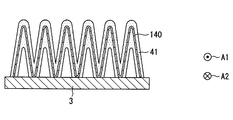
第2実施形態は、吸湿材41が設けられる複数の板状部材140が第1実施形態と相違する。吸湿材41は、冷却装置5と一体に設けられた複数の板状部材140の表面にたんじされている。板状部材140は、波状に折り曲げられたコルゲート板である。吸湿材モジュールは、吸湿材41を担持させた複数のコルゲート板を間隔を開けて積層設置して構成される。
第2実施形態の吸湿部は、冷却部と一体に設けられた複数の板状部材140の表面に設けられている。この構成によれば、周囲温度よりも低温に制御可能な冷却装置5に複数の板状部材140を一体に形成、結合等する簡易な構成により、吸湿材41を直接的に冷却可能な装置を提供できる。この構成は、加湿装置1の小型化と吸湿速度の向上とに貢献できる。
また、第2実施形態によれば、内部に冷媒が流れて蒸発する蒸発器におけるアウターフィンを板状部材40として活用することができる。つまり、第2実施形態の加湿装置は蒸発器のチューブに接触するアウターフィンの表面に吸湿材41を被覆することにより、構成することができる。
(第3実施形態)
第3実施形態について図5を参照して説明する。第3実施形態において、第1実施形態に係る図面と同一符号を付した構成部品及び説明しない構成は、第1実施形態と同様であり、同様の作用効果を奏するものである。第3実施形態では、第1実施形態と異なる部分のみ説明する。
第3実施形態について図5を参照して説明する。第3実施形態において、第1実施形態に係る図面と同一符号を付した構成部品及び説明しない構成は、第1実施形態と同様であり、同様の作用効果を奏するものである。第3実施形態では、第1実施形態と異なる部分のみ説明する。
第3実施形態は、吸湿材41が設けられるヒートシンク240を冷却装置5で冷却する点が第1実施形態に対して相違する。ヒートシンク240は、熱移動可能に冷却装置5に接触した状態で冷却装置5に一体に設けられる基台部と、基台部から延びるように立設する複数個の板状部と、を備える。
ヒートシンク240は、伝熱性に優れる金属、例えば、アルミニウム、銅で形成された複数の板状部を有する伝熱性部材である。ヒートシンク240は、吸湿材41や板状部から冷却装置5へ熱を移動させる機能を果たす。ヒートシンク240は、冷却装置5の冷却能力を利用して空気通路62を流れる空気と吸湿材41とを熱交換させることができる。
第3実施形態によれば、内部で冷媒が蒸発する蒸発器におけるアウターフィンをヒートシンク240として活用することができる。つまり、第3実施形態の加湿装置は蒸発器のチューブに接触するアウターフィンの表面に吸湿材41を被覆することにより、構成することができる。
(第4実施形態)
第4実施形態について図6および図7を参照して説明する。第4実施形態において、第1実施形態に係る図面と同一符号を付した構成部品及び説明しない構成は、第1実施形態と同様であり、同様の作用効果を奏するものである。第4実施形態では、第1実施形態と異なる部分のみ説明する。
第4実施形態について図6および図7を参照して説明する。第4実施形態において、第1実施形態に係る図面と同一符号を付した構成部品及び説明しない構成は、第1実施形態と同様であり、同様の作用効果を奏するものである。第4実施形態では、第1実施形態と異なる部分のみ説明する。
第4実施形態の加湿装置101は、吸湿部と加熱部とを一体に形成する点が第1実施形態に対して相違する。
図6に示すように、加湿装置101においては、吸湿素子からの水分の脱離時に空気が流れる方向A2について、上流側に加熱装置3および吸湿材モジュール4、下流側に冷却装置5が並ぶように設置されている。したがって、脱離時に、第2開口部61から導入された車室内空気は、加熱装置3で加熱された吸湿材モジュール4を通過する際に水分が加えられた後、冷却装置5で冷却されてから第1開口部60から車室内へ吹き出される。
加湿装置101には、吸湿素子への水分の吸湿時に空気が流れる方向A1に、上流側に冷却装置5、下流側に吸湿材モジュール4および加熱装置3が並ぶように設置されている。したがって、吸湿時に第1開口部60から導入された車室内空気は、冷却装置5によって冷却された後、加熱装置3によって加熱された吸湿材モジュール4を通過する際に吸湿材41に水分を放出し、除湿された状態で第2開口部61から車室内へ吹き出される。
図3に図示するように、加熱装置3における空気通路62側の面または空気通路62に露出する面は、間隔をあけて立設する複数の板状部材40と熱移動可能に結合されている。
制御装置が送風装置2の電動モータを正転させると、車室内Rの空気が第2開口部61を介して加湿装置101の空気通路62へ吸い込まれる。空気通路62に吸い込まれた送風空気は、吸湿材モジュール4に流入する際に、加熱装置3によって加熱された吸湿材41や板状部材40に接触する。この際、吸湿材41が加熱されるので、吸湿材41に接触する空気には吸湿材41に吸着している水分が脱離しやすい状況となる。つまり、加熱された吸湿材41は保持している水分を放出しやすく、吸湿材モジュール4を流出後の空気は、十分に加湿された加湿空気となる。この加湿空気は、冷却装置5によって冷却された後、第1開口部60から乗員に向けて吹き出される。
制御装置が送風装置2の電動モータを反転させると、車室内Rの空気が第1開口部60を介して加湿装置1の空気通路62に吸い込まれる。空気通路62に吸い込まれた送風空気は、冷却装置5によって冷却されて温度低下するので、相対湿度が高い状態になる。相対湿度が高くなった送風空気は、吸湿材モジュール4に流入する際に、吸湿材41に接触する。相対湿度が高くなった送風空気の水分は、吸湿材41に吸着しやすい状況となり、吸湿速度を向上することができる。さらに、水分を放出した送風空気は、加熱装置3を通過する際に加熱され、第2開口部61を介して後部座席側や車室内の下方に吹き出される。
この吸湿時には、冷却装置5によって空気を冷却してから、吸湿材41に吸湿させることで、水分の吸湿速度を高めることができる。
第2実施形態の加湿装置101は、一体に形成された吸湿部と加熱部を備える。この構成によれば、吸湿部および加熱部を一体に形成することにより、吸湿部を直接、加熱することができる。これによれば、空気を介して吸湿部を加熱する場合に比べて、吸湿部の温度を迅速に上昇できるので、吸湿部からの水分の脱離速度を向上させることができる。さらに、空気通路62に設置される吸湿部と加熱部とを一体に形成することにより、加湿装置101が備える空気通路62を短く構成することにも貢献できる。したがって、加湿へのモード切換え応答性の向上と空気流れ方向の装置寸法の小型化とを図る加湿装置101を提供できる。
また、加湿装置101における吸湿部は、加熱部と一体に設けられた複数の板状部材40の表面に設けられている。この構成によれば、周囲温度よりも高温に制御可能な加熱装置3に複数の板状部材40を一体に形成、結合等する簡易な構成により、吸湿材41を直接的に加熱可能な装置を提供できる。したがって、この構成は、加湿装置101の小型化と脱離速度の向上とに貢献できる。
(第5実施形態)
第5実施形態について図8を参照して説明する。第5実施形態において、第1実施形態、第4実施形態に係る図面と同一符号を付した構成部品及び説明しない構成は、前述の実施形態と同様であり、同様の作用効果を奏するものである。第5実施形態では、前述の実施形態と異なる部分のみ説明する。
第5実施形態について図8を参照して説明する。第5実施形態において、第1実施形態、第4実施形態に係る図面と同一符号を付した構成部品及び説明しない構成は、前述の実施形態と同様であり、同様の作用効果を奏するものである。第5実施形態では、前述の実施形態と異なる部分のみ説明する。
第5実施形態は、吸湿材41が設けられる複数の板状部材140が第4実施形態と相違する。吸湿材41は、加熱装置3と一体に設けられた複数の板状部材140の表面に担持されている。
第5実施形態によれば、内部に冷媒が流れて蒸発する蒸発器におけるアウターフィンを板状部材40として活用することができる。つまり、第5実施形態の加湿装置は蒸発器のチューブに接触するアウターフィンの表面に吸湿材41を被覆することにより、構成することができる。
(第6実施形態)
第6実施形態について図9を参照して説明する。第6実施形態において、第1実施形態、第4実施形態に係る図面と同一符号を付した構成部品及び説明しない構成は、前述の実施形態と同様であり、同様の作用効果を奏するものである。第6実施形態では、前述の実施形態と異なる部分のみ説明する。
第6実施形態について図9を参照して説明する。第6実施形態において、第1実施形態、第4実施形態に係る図面と同一符号を付した構成部品及び説明しない構成は、前述の実施形態と同様であり、同様の作用効果を奏するものである。第6実施形態では、前述の実施形態と異なる部分のみ説明する。
第6実施形態は、加熱装置103においてそれ自体が発熱する板状の発熱部の表面に吸湿材41が設けられている点が第4実施形態と相違する。吸湿材41は、加熱装置103における板状の発熱部の表面に担持されている。発熱部は断面形状が波形となるように形成されている。例えば、発熱部は、板材をジグザグに折り曲げることで形成することができる。吸湿材41は、板状の発熱部の表面全体に被覆されていることが好ましい。
第6実施形態によれば、吸湿材41を板状の発熱部の表面に一体に設けることにより、吸湿材41の表面積を大きく設定することができる。これにより、吸湿材41を板状の表面において広く設けることができるので、水分の吸湿量と脱離する水分量とを高めた加湿装置を提供できる。
(第7実施形態)
第7実施形態について図10および図11を参照して説明する。第7実施形態において、第1実施形態、第4実施形態に係る図面と同一符号を付した構成部品及び説明しない構成は、前述の実施形態と同様であり、同様の作用効果を奏するものである。第7実施形態では、前述の実施形態と異なる部分のみ説明する。
第7実施形態について図10および図11を参照して説明する。第7実施形態において、第1実施形態、第4実施形態に係る図面と同一符号を付した構成部品及び説明しない構成は、前述の実施形態と同様であり、同様の作用効果を奏するものである。第7実施形態では、前述の実施形態と異なる部分のみ説明する。
第7実施形態は、加熱装置203においてそれ自体が発熱するコイル状の発熱部の表面に吸湿材41が設けられている点が第4実施形態と相違する。吸湿材41は、加熱装置203におけるコイル状の発熱部の表面に担持されている。発熱部は、断面形状が円形である線材をコイル状に巻回した外形を呈する。例えば、発熱部は、線状発熱体であり、ニクロム線等の線材をコイル状に巻くことで形成することができる。吸湿材41は、コイル状を形成する線材の表面全体に被覆されていることが好ましい。
第7実施形態によれば、吸湿材41をコイル状の発熱部の表面に一体に設けることにより、吸湿材41の表面積を大きく設定することができる。これにより、巻数を増やすことで水分の吸湿量と脱離する水分量とを増加可能な加湿装置を提供できる。
(第8実施形態)
第8実施形態について図12を参照して説明する。第8実施形態において、第1実施形態、第4実施形態に係る図面と同一符号を付した構成部品及び説明しない構成は、前述の実施形態と同様であり、同様の作用効果を奏するものである。第8実施形態では、前述の実施形態と異なる部分のみ説明する。
第8実施形態について図12を参照して説明する。第8実施形態において、第1実施形態、第4実施形態に係る図面と同一符号を付した構成部品及び説明しない構成は、前述の実施形態と同様であり、同様の作用効果を奏するものである。第8実施形態では、前述の実施形態と異なる部分のみ説明する。
第8実施形態は、それ自体が発熱する板状の発熱部の表面に吸湿材41が設けて加熱装置303と吸湿材41とを一体に形成する点が第4実施形態と相違する。吸湿材41は、加熱装置303が有する板状の発熱部の表面に担持されている。発熱部は断面形状が細長い矩形状となるように形成されている。例えば、発熱部には、PTC面状ヒータ、面状カーボンヒータ等の面状発熱体を用いることができる。吸湿材41は、発熱部を構成する面状体の表面全体に被覆されていることが好ましい。また、板状の発熱部を間隔をあけて表面同士を対向させた姿勢で、複数個重ねることで加熱装置303を構成してもよい。
第8実施形態によれば、吸湿材41を板状の発熱部の表面に一体に設けることにより、吸湿材41の表面積を大きく設定することができる。これにより、吸湿材41を板状の表面において広く設置できるので、水分の吸湿量と脱離する水分量とを高めた加湿装置を提供できる。
さらに、板状の発熱部を間隔をあけて表面同士を対向させた姿勢で、複数個重ねて加熱装置303を構成することにより、空気通路62において空気が流れる複数の小通路を形成でき、小通路ごとに吸湿材41に接触する空気流れを形成できる。したがって、小通路ごとに吸湿材41の表面積を大きく設定できるので、空気流れ全体として吸湿量、水分脱離量を高めた加湿装置を提供できる。
(第9実施形態)
第9実施形態について図13及び図14を参照して説明する。第9実施形態において第1実施形態に係る図面と同一符号を付した構成部品及び説明しない構成は、第1実施形態と同様であり、同様の作用効果を奏するものである。第9実施形態では、第1実施形態と異なる部分のみ説明する。
第9実施形態について図13及び図14を参照して説明する。第9実施形態において第1実施形態に係る図面と同一符号を付した構成部品及び説明しない構成は、第1実施形態と同様であり、同様の作用効果を奏するものである。第9実施形態では、第1実施形態と異なる部分のみ説明する。
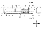
第9実施形態の加湿装置201は、加熱装置と冷却装置の両方の機能を有するペルチェモジュール7が吸湿材モジュール4と一体に設けられる点が第1実施形態の加湿装置1に対して相違する。ペルチェモジュール7はペルチェ素子を有する。制御装置がペルチェ素子に流れる電流の向きを変更することによって、ペルチェ素子の一方側面または他方側面が吸熱または発熱する。ペルチェ素子は、空気通路62側に位置する一方側板部と、車室外側に位置する他方側板部と、を有する。
ペルチェモジュール7は、ペルチェ素子の一方側板部に相当する空気通路62側の面において吸湿材モジュール4と一体になるように設けられている。図14に図示するように、ペルチェモジュール7における空気通路62側の面は、図3と同様に、間隔をあけて立設する複数の板状部材40と熱移動可能に結合されている。
ペルチェ素子は、2種類の金属の接合部に電流を流すと、片方の金属からもう片方へ熱が移動するペルチェ効果を利用した素子であり、可動部を備えない。ペルチェ素子は、例えば、2種の金属板の間にP型半導体とN型半導体とを複数配置するとともに、一方の金属板によってN-P接合を構成し、かつ他方の金属板によってP-N接合を構成した素子である。ペルチェ素子では、PN接合部分に電流を流すことにより、N→P接合部分に相当する金属板で吸熱現象が生じ、P→N接合部分に相当する金属板で放熱現象が生じる。したがって、ペルチェ素子における一方側板部、他方側板部のそれぞれは、N型半導体からP型半導体へ電流が流れるように橋渡しする場合には吸熱する吸熱部となり、P型半導体からN型半導体へ電流が流れるように橋渡しする場合には発熱する放熱部となる。
制御装置の制御により、N型半導体、一方側板部、P型半導体の順に電流が流れる場合には、一方側板部及び板状部材40が吸熱部となり、車室外側の他方側板部が放熱部となる。この場合、ペルチェモジュール7は、冷却部として機能する。送風装置2によって第1開口部60から吸い込まれた車室内の空気は、方向A1に流れ、板状部材40の周囲を通過する時に吸熱されて冷却される。空気から板状部材40に移動した熱は、ペルチェ素子の他方側板部へ伝わり、車室外に排出される。空気通路62を流れる空気は、水分が吸湿材41で吸着された後、第2開口部61から除湿空気として車室内へ吹き出される。
制御装置の制御により、P型半導体、一方側板部、N型半導体の順に電流が流れる場合には、一方側板部及び板状部材40が放熱部となり、車室外側の他方側板部が吸熱部となる。この場合、ペルチェモジュール7は、加熱部として機能する。送風装置2によって第2開口部61から吸い込まれた車室内の空気は、方向A2に流れ、板状部材40の周囲を通過する時に放熱により加熱される。空気通路62を流れる空気は、吸湿材41から脱離された水分によって、第1開口部60から加湿空気として車室内へ吹き出される。以上のように、ペルチェモジュール7は、通電状態に応じて、空気から吸熱する吸熱部と空気へ放熱する放熱部と、を有する装置である。
加湿装置201は、同一の空気通路62における空気流れ方向を逆向きに変化させて、空気に対する水分の吸収と放出とを切り換える装置である。加湿装置201は、加熱部と、冷却部と、空気通路62に設けられ空気に対して吸着されている水分を脱離し空気から水分を吸着する吸湿部と、空気通路62において脱離時と吸着時とで互いに逆向きの空気流れ方向を発生させる送風部と、を備える。吸湿部、冷却部および加熱部は、一体に形成されている。
この構成によれば、吸湿部、冷却部および加熱部を一体に形成することにより、吸湿部を直接、加熱したり冷却したりすることができる。これによれば、空気を介して吸湿部を冷却する場合に比べて、吸湿部の温度を迅速に低下でき、また低く保つことができるので、吸湿部への水分の吸収を迅速に行うことができる。また、空気を介して吸湿部を加熱する場合に比べて、吸湿部の温度を迅速に上昇できるので、吸湿部からの水分の脱離速度を向上することができる。さらに、空気通路62に設置される吸湿部と冷却部と加熱部とを一体に形成することにより、加湿装置201が備える空気通路62を短く構成することにも貢献できる。したがって、加湿および除湿へのモード切換え応答性の向上と空気流れ方向の装置寸法の小型化とを図る加湿装置201を提供できる。
第9実施形態によれば、吸湿材41は、ペルチェモジュール7に一体に設けられた複数の板状部材40の表面に設けられている。この構成により、吸湿部、加熱部および冷却部を一体に形成した加湿装置201を提供できるため、吸湿部を直接、加熱および冷却することができる。これによれば、空気を介して吸湿部を加熱し冷却する場合に比べて吸湿材41からの水分の脱離と吸湿材41への水分の吸収とを迅速に行える。さらに、加湿装置201は、電流の向きに応じて冷却部の機能と加熱部の機能とを切換え可能なペルチェモジュール7を備えるため、空気流れ方向の装置寸法を低減することができる。
(第10実施形態)
第10実施形態について図15及び図16を参照して説明する。第10実施形態において第1実施形態に係る図面と同一符号を付した構成部品及び説明しない構成は、第1実施形態と同様であり、同様の作用効果を奏するものである。第10実施形態では、第1実施形態と異なる部分のみ説明する。
第10実施形態について図15及び図16を参照して説明する。第10実施形態において第1実施形態に係る図面と同一符号を付した構成部品及び説明しない構成は、第1実施形態と同様であり、同様の作用効果を奏するものである。第10実施形態では、第1実施形態と異なる部分のみ説明する。
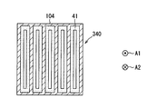
第10実施形態の加湿装置は、吸湿材41が設けられている熱交換部材340に、加熱装置3および冷却装置5が一体に設けられている点が第1実施形態の加湿装置1に対して相違する。第10実施形態の加湿装置は、空気通路62に設けられて空気通路62を流れる空気と熱交換する熱交換部材340を備える。熱交換部材340は、例えばアルミニウム、銅等の熱伝導性を有する材質で形成されており、内部に空気が流れる内部通路を有する箱体状の部材である。例えば、熱交換部材340は、内部に複数に仕切られた内部通路を有する。
加熱装置3は、空気流れ方向について熱交換部材340の一方側部を加熱するように設けられる。冷却装置5は、空気流れ方向について熱交換部材340の他方側部を冷却するように設けられる。吸湿材41は、一方側部と他方側部との間に位置して所定の範囲を占める中間部104において、空気と接触する表面に設けられている。中間部104は、各内部通路を形成する壁面に吸湿材41を担持する。
制御装置が送風装置2の電動モータを正転させると、車室内Rの空気が第2開口部61を介して空気通路62へ吸い込まれる。空気通路62に吸い込まれた送風空気は、加熱装置3によって加熱された熱交換部材340の一方側部における内部通路を通過するときに加熱される。この際、熱交換部材340の一方側部を通過後の送風空気の温度が車室内Rの空気温度よりも上昇する。
熱交換部材340の一方側部を通過後の送風空気は、中間部104に流入する。この際、送風空気の相対湿度は、車室内Rの空気の相対湿度よりも低下している。したがって、相対湿度が下がった送風空気を、中間部104に担持させた吸湿材41に接触させることで、吸湿材41に吸着している水分が空気に脱離しやすい状況となる。つまり、加熱装置3によって相対湿度が下げられた空気は、吸湿材41が保持している水分を含みやすく、中間部104を流出後の空気は、十分に加湿された加湿空気となる。この加湿空気は、さらに冷却装置5によって冷却された熱交換部材340の他方側部における内部通路を通過するときに冷却される。この際、熱交換部材340の他方側部を通過後の送風空気は、加湿空気であって、温度低下された涼風になり、第1開口部60から乗員に向けて吹き出される。なお、加熱装置3による加熱出力と冷却装置5による冷却出力は、吸湿材41を加熱するために加熱出力の方が支配的であることが好ましい。
制御装置が送風装置2の電動モータを反転させると、車室内Rの空気が、第1開口部60を介して空気通路62に吸い込まれる。空気通路62に吸い込まれた送風空気は、冷却装置5によって冷却された熱交換部材340の他方側部における内部通路を通過するときに冷却される。
熱交換部材340の他方側部を通過後の送風空気は、中間部104に流入する。この際、送風空気は、冷却装置5によって冷却された吸湿材41に接触する。吸湿材41が冷却されることで空気の水分が吸湿材41に吸着しやすい状況となり、吸湿速度を向上することができる。さらに、水分を放出した送風空気は、熱交換部材340の一方側部を通過する際に加熱され、第2開口部61を介して後部座席側や車室内の下方に吹き出される。
この吸湿時には、冷却装置5によって中間部104における吸湿材41を冷却することで、空気から水分を吸湿する吸湿速度を高めることができる。このため中間部104における水分吸着が活発に行われ、中間部104を流出後の空気の相対湿度を迅速に低下させることができる。なお、加熱装置3による加熱出力と冷却装置5による冷却出力は、吸湿材41を冷却するために冷却出力の方が支配的であることが好ましい。
第10実施形態によれば、吸湿部と冷却部と加熱部とは一体に形成されている。この構成により、吸湿部を直接、加熱したり冷却したりすることができる。これによれば、吸湿部の温度を迅速に低下でき、また低く保つことができるので、吸湿部への水分の吸収を迅速に行うことができる。また、吸湿部の温度を迅速に上昇できるので、吸湿部からの水分の脱離速度を向上することができる。さらに、空気通路62に設置される吸湿部と冷却部と加熱部とを熱交換部材340を介して一体に形成することにより、加湿装置が備える空気通路62を短く構成することにも貢献できる。したがって、第10実施形態の加湿装置は、加湿および除湿へのモード切換え応答性の向上と空気流れ方向の装置寸法の小型化とを図ることができる。
この明細書の開示は、例示された実施形態に制限されない。開示は、例示された実施形態と、それらに基づく当業者による変形態様を包含する。例えば、開示は、実施形態において示された部品、要素の組み合わせに限定されず、種々変形して実施することが可能である。開示は、多様な組み合わせによって実施可能である。開示は、実施形態に追加可能な追加的な部分をもつことができる。開示は、実施形態の部品、要素が省略されたものを包含する。開示は、ひとつの実施形態と他の実施形態との間における部品、要素の置き換え、または組み合わせを包含する。開示される技術的範囲は、実施形態の記載に限定されない。
吸湿材モジュールの構成は、前述の実施形態に記載した構成に限定されない。例えば、断面六角形に形成された通路を有するハニカム部材に吸湿材41を担持させたものを採用してもよい。
前述の第1実施形態では、制御装置が送風装置2の電動モータを正転あるいは逆転させることによって、通風方向を切り替える構成について説明したが、通風経路の切り替えはこれに限定されない。
前述の実施形態では、加湿装置は、車両の天井材の裏側に設置されているが、この設置場所に限定されない。例えば、加湿装置1は、例えば、インストルメントパネル、ドアトリム、ステアリングコラム、トランクルームと連通する内装部材等の裏側に搭載することができる。
前述の実施形態では、吸着時に加湿装置に導入される空気として車室内Rの空気を採用した例を説明したが、車室外の空気、例えば、外気を導入するようにしてもよい。
前述の実施形態では、加湿空気が車両の前席側に供給されるように第1開口部60が前席側に位置し、除湿空気が車両の後席側に供給されるように第2開口部61が後席側に位置しているが、この位置関係に限定するものではない。
前述の実施形態では、第1開口部60を車両前席に着座している乗員の上半身側に向かって開口させるように配置し、第2開口部61を後部座席側に向かって開口させるように配置しているが、各開口部の配置はこれに限定さない。
本開示は、実施例に準拠して記述されたが、本開示は当該実施例や構造に限定されるものではないと理解される。本開示は、様々な変形例や均等範囲内の変形をも包含する。加えて、様々な組み合わせや形態、さらには、それらに一要素のみ、それ以上、あるいはそれ以下、を含む他の組み合わせや形態をも、本開示の範疇や思想範囲に入るものである。
Claims (8)
- 同一の空気通路(62)における空気流れ方向を逆向きに変化させて、空気に対する水分の吸収と放出とを切り換える加湿装置(1)であって、
熱を発生する加熱部(3;103;203;303)と、
吸熱する冷却部(5)と、
前記空気通路に設けられ、空気に対して吸着されている水分を脱離し空気から水分を吸着する吸湿部(41)と、
前記空気通路において脱離時と吸着時とで互いに逆向きの空気流れ方向を発生させる送風部(2)と、
を備え、
前記吸湿部と、前記加熱部および前記冷却部の少なくとも一つとを一体に形成した加湿装置。 - 前記吸湿部は、前記冷却部と一体に設けられた複数の板状部材(40;140)の表面に設けられている請求項1に記載の加湿装置。
- 前記吸湿部は、熱移動可能に前記冷却部に接触するヒートシンク(240)の表面に設けられている請求項1に記載の加湿装置。
- 前記吸湿部は、前記加熱部の発熱が伝わるように前記加熱部と一体に設けられた複数の板状部材(40;140)の表面に設けられている請求項1に記載の加湿装置。
- 前記加熱部は、それ自体が発熱する板状の発熱部(103;303)を有し、
前記吸湿部は、前記発熱部の表面に設けられている請求項1に記載の加湿装置。 - 前記加熱部は、それ自体が発熱するコイル状の発熱部(203)を有し、
前記吸湿部は、前記発熱部の表面に設けられている請求項1に記載の加湿装置。 - 前記空気通路に設けられて前記空気通路を流れる空気と熱交換する熱交換部材(340)を備え、
前記加熱部は、前記空気流れ方向について前記熱交換部材の一方側部を加熱するように設けられ、
前記冷却部は、前記空気流れ方向について前記熱交換部材の他方側部を冷却するように設けられ、
前記吸湿部は、前記一方側部と前記他方側部との間に位置する中間部(104)において空気と接触する表面に設けられている請求項1に記載の加湿装置。 - 前記吸湿部は、ペルチェ素子を有するペルチェモジュール(7)に一体に設けられた複数の板状部材(40)の表面に設けられている請求項1に記載の加湿装置。
Applications Claiming Priority (2)
| Application Number | Priority Date | Filing Date | Title |
|---|---|---|---|
| JP2016-015184 | 2016-01-29 | ||
| JP2016015184A JP2017133778A (ja) | 2016-01-29 | 2016-01-29 | 加湿装置 |
Publications (1)
| Publication Number | Publication Date |
|---|---|
| WO2017130547A1 true WO2017130547A1 (ja) | 2017-08-03 |
Family
ID=59397913
Family Applications (1)
| Application Number | Title | Priority Date | Filing Date |
|---|---|---|---|
| PCT/JP2016/084875 Ceased WO2017130547A1 (ja) | 2016-01-29 | 2016-11-25 | 加湿装置 |
Country Status (2)
| Country | Link |
|---|---|
| JP (1) | JP2017133778A (ja) |
| WO (1) | WO2017130547A1 (ja) |
Citations (5)
| Publication number | Priority date | Publication date | Assignee | Title |
|---|---|---|---|---|
| JPH04227816A (ja) * | 1990-05-15 | 1992-08-17 | Erling Berner | 除湿装置 |
| JP2009264635A (ja) * | 2008-04-23 | 2009-11-12 | Denso Corp | 除加湿装置 |
| JP2010091156A (ja) * | 2008-10-06 | 2010-04-22 | Denso Corp | 除加湿装置 |
| JP2013178083A (ja) * | 2012-02-06 | 2013-09-09 | Daikin Industries Ltd | 空気調和装置 |
| JP2014202426A (ja) * | 2013-04-05 | 2014-10-27 | 株式会社デンソー | 加湿装置 |
Family Cites Families (1)
| Publication number | Priority date | Publication date | Assignee | Title |
|---|---|---|---|---|
| JP2010270973A (ja) * | 2009-05-21 | 2010-12-02 | Daikin Ind Ltd | 吸着熱交換器およびその製造方法 |
-
2016
- 2016-01-29 JP JP2016015184A patent/JP2017133778A/ja active Pending
- 2016-11-25 WO PCT/JP2016/084875 patent/WO2017130547A1/ja not_active Ceased
Patent Citations (5)
| Publication number | Priority date | Publication date | Assignee | Title |
|---|---|---|---|---|
| JPH04227816A (ja) * | 1990-05-15 | 1992-08-17 | Erling Berner | 除湿装置 |
| JP2009264635A (ja) * | 2008-04-23 | 2009-11-12 | Denso Corp | 除加湿装置 |
| JP2010091156A (ja) * | 2008-10-06 | 2010-04-22 | Denso Corp | 除加湿装置 |
| JP2013178083A (ja) * | 2012-02-06 | 2013-09-09 | Daikin Industries Ltd | 空気調和装置 |
| JP2014202426A (ja) * | 2013-04-05 | 2014-10-27 | 株式会社デンソー | 加湿装置 |
Also Published As
| Publication number | Publication date |
|---|---|
| JP2017133778A (ja) | 2017-08-03 |
Similar Documents
| Publication | Publication Date | Title |
|---|---|---|
| US9752788B2 (en) | Humidification device | |
| JP5239717B2 (ja) | 除加湿装置 | |
| JP6394521B2 (ja) | 加湿装置 | |
| JP2009274587A (ja) | 車両用除加湿装置 | |
| JP6413680B2 (ja) | 加湿装置 | |
| CN107428226A (zh) | 冷却装置、车辆用空调装置 | |
| JP2010025448A (ja) | 除加湿装置 | |
| US10675951B2 (en) | Humidifying device | |
| JP2010096454A (ja) | 除加湿装置 | |
| JP6658917B2 (ja) | 加湿装置 | |
| JP5083035B2 (ja) | 車両用除加湿装置及びその装置の運転方法 | |
| JP2009293837A (ja) | 除加湿装置 | |
| JP2009262580A (ja) | 車両用除加湿装置 | |
| JP2010002082A (ja) | 除加湿装置 | |
| JP2009264635A (ja) | 除加湿装置 | |
| CN107405986A (zh) | 加湿装置、车辆用空调装置 | |
| JP2009280149A (ja) | 車両用除加湿装置 | |
| WO2017130547A1 (ja) | 加湿装置 | |
| JP6350483B2 (ja) | 加湿装置 | |
| JP2016090125A (ja) | 加湿装置 | |
| JP2009293835A (ja) | 除加湿装置 | |
| JP2009264636A (ja) | 除加湿装置 | |
| JP2017105407A (ja) | 加湿装置 | |
| JP2009293836A (ja) | 除加湿装置 | |
| JP2010002122A (ja) | 除加湿装置 |
Legal Events
| Date | Code | Title | Description |
|---|---|---|---|
| 121 | Ep: the epo has been informed by wipo that ep was designated in this application |
Ref document number: 16888131 Country of ref document: EP Kind code of ref document: A1 |
|
| NENP | Non-entry into the national phase |
Ref country code: DE |
|
| 122 | Ep: pct application non-entry in european phase |
Ref document number: 16888131 Country of ref document: EP Kind code of ref document: A1 |