WO2017126685A1 - スタータ - Google Patents
スタータ Download PDFInfo
- Publication number
- WO2017126685A1 WO2017126685A1 PCT/JP2017/002002 JP2017002002W WO2017126685A1 WO 2017126685 A1 WO2017126685 A1 WO 2017126685A1 JP 2017002002 W JP2017002002 W JP 2017002002W WO 2017126685 A1 WO2017126685 A1 WO 2017126685A1
- Authority
- WO
- WIPO (PCT)
- Prior art keywords
- pinion gear
- engine
- starter
- motor
- ring gear
- Prior art date
- Legal status (The legal status is an assumption and is not a legal conclusion. Google has not performed a legal analysis and makes no representation as to the accuracy of the status listed.)
- Ceased
Links
Images




Classifications
-
- F—MECHANICAL ENGINEERING; LIGHTING; HEATING; WEAPONS; BLASTING
- F02—COMBUSTION ENGINES; HOT-GAS OR COMBUSTION-PRODUCT ENGINE PLANTS
- F02N—STARTING OF COMBUSTION ENGINES; STARTING AIDS FOR SUCH ENGINES, NOT OTHERWISE PROVIDED FOR
- F02N11/00—Starting of engines by means of electric motors
- F02N11/08—Circuits specially adapted for starting of engines
- F02N11/0803—Circuits specially adapted for starting of engines characterised by means for initiating engine start or stop
-
- B—PERFORMING OPERATIONS; TRANSPORTING
- B60—VEHICLES IN GENERAL
- B60K—ARRANGEMENT OR MOUNTING OF PROPULSION UNITS OR OF TRANSMISSIONS IN VEHICLES; ARRANGEMENT OR MOUNTING OF PLURAL DIVERSE PRIME-MOVERS IN VEHICLES; AUXILIARY DRIVES FOR VEHICLES; INSTRUMENTATION OR DASHBOARDS FOR VEHICLES; ARRANGEMENTS IN CONNECTION WITH COOLING, AIR INTAKE, GAS EXHAUST OR FUEL SUPPLY OF PROPULSION UNITS IN VEHICLES
- B60K6/00—Arrangement or mounting of plural diverse prime-movers for mutual or common propulsion, e.g. hybrid propulsion systems comprising electric motors and internal combustion engines
- B60K6/20—Arrangement or mounting of plural diverse prime-movers for mutual or common propulsion, e.g. hybrid propulsion systems comprising electric motors and internal combustion engines the prime-movers consisting of electric motors and internal combustion engines, e.g. HEVs
- B60K6/22—Arrangement or mounting of plural diverse prime-movers for mutual or common propulsion, e.g. hybrid propulsion systems comprising electric motors and internal combustion engines the prime-movers consisting of electric motors and internal combustion engines, e.g. HEVs characterised by apparatus, components or means specially adapted for HEVs
-
- B—PERFORMING OPERATIONS; TRANSPORTING
- B60—VEHICLES IN GENERAL
- B60K—ARRANGEMENT OR MOUNTING OF PROPULSION UNITS OR OF TRANSMISSIONS IN VEHICLES; ARRANGEMENT OR MOUNTING OF PLURAL DIVERSE PRIME-MOVERS IN VEHICLES; AUXILIARY DRIVES FOR VEHICLES; INSTRUMENTATION OR DASHBOARDS FOR VEHICLES; ARRANGEMENTS IN CONNECTION WITH COOLING, AIR INTAKE, GAS EXHAUST OR FUEL SUPPLY OF PROPULSION UNITS IN VEHICLES
- B60K6/00—Arrangement or mounting of plural diverse prime-movers for mutual or common propulsion, e.g. hybrid propulsion systems comprising electric motors and internal combustion engines
- B60K6/20—Arrangement or mounting of plural diverse prime-movers for mutual or common propulsion, e.g. hybrid propulsion systems comprising electric motors and internal combustion engines the prime-movers consisting of electric motors and internal combustion engines, e.g. HEVs
- B60K6/22—Arrangement or mounting of plural diverse prime-movers for mutual or common propulsion, e.g. hybrid propulsion systems comprising electric motors and internal combustion engines the prime-movers consisting of electric motors and internal combustion engines, e.g. HEVs characterised by apparatus, components or means specially adapted for HEVs
- B60K6/26—Arrangement or mounting of plural diverse prime-movers for mutual or common propulsion, e.g. hybrid propulsion systems comprising electric motors and internal combustion engines the prime-movers consisting of electric motors and internal combustion engines, e.g. HEVs characterised by apparatus, components or means specially adapted for HEVs characterised by the motors or the generators
-
- B—PERFORMING OPERATIONS; TRANSPORTING
- B60—VEHICLES IN GENERAL
- B60K—ARRANGEMENT OR MOUNTING OF PROPULSION UNITS OR OF TRANSMISSIONS IN VEHICLES; ARRANGEMENT OR MOUNTING OF PLURAL DIVERSE PRIME-MOVERS IN VEHICLES; AUXILIARY DRIVES FOR VEHICLES; INSTRUMENTATION OR DASHBOARDS FOR VEHICLES; ARRANGEMENTS IN CONNECTION WITH COOLING, AIR INTAKE, GAS EXHAUST OR FUEL SUPPLY OF PROPULSION UNITS IN VEHICLES
- B60K6/00—Arrangement or mounting of plural diverse prime-movers for mutual or common propulsion, e.g. hybrid propulsion systems comprising electric motors and internal combustion engines
- B60K6/20—Arrangement or mounting of plural diverse prime-movers for mutual or common propulsion, e.g. hybrid propulsion systems comprising electric motors and internal combustion engines the prime-movers consisting of electric motors and internal combustion engines, e.g. HEVs
- B60K6/42—Arrangement or mounting of plural diverse prime-movers for mutual or common propulsion, e.g. hybrid propulsion systems comprising electric motors and internal combustion engines the prime-movers consisting of electric motors and internal combustion engines, e.g. HEVs characterised by the architecture of the hybrid electric vehicle
- B60K6/48—Parallel type
-
- B—PERFORMING OPERATIONS; TRANSPORTING
- B60—VEHICLES IN GENERAL
- B60W—CONJOINT CONTROL OF VEHICLE SUB-UNITS OF DIFFERENT TYPE OR DIFFERENT FUNCTION; CONTROL SYSTEMS SPECIALLY ADAPTED FOR HYBRID VEHICLES; ROAD VEHICLE DRIVE CONTROL SYSTEMS FOR PURPOSES NOT RELATED TO THE CONTROL OF A PARTICULAR SUB-UNIT
- B60W20/00—Control systems specially adapted for hybrid vehicles
- B60W20/10—Controlling the power contribution of each of the prime movers to meet required power demand
-
- F—MECHANICAL ENGINEERING; LIGHTING; HEATING; WEAPONS; BLASTING
- F02—COMBUSTION ENGINES; HOT-GAS OR COMBUSTION-PRODUCT ENGINE PLANTS
- F02N—STARTING OF COMBUSTION ENGINES; STARTING AIDS FOR SUCH ENGINES, NOT OTHERWISE PROVIDED FOR
- F02N11/00—Starting of engines by means of electric motors
- F02N11/04—Starting of engines by means of electric motors the motors being associated with current generators
-
- F—MECHANICAL ENGINEERING; LIGHTING; HEATING; WEAPONS; BLASTING
- F02—COMBUSTION ENGINES; HOT-GAS OR COMBUSTION-PRODUCT ENGINE PLANTS
- F02N—STARTING OF COMBUSTION ENGINES; STARTING AIDS FOR SUCH ENGINES, NOT OTHERWISE PROVIDED FOR
- F02N11/00—Starting of engines by means of electric motors
- F02N11/08—Circuits specially adapted for starting of engines
-
- F—MECHANICAL ENGINEERING; LIGHTING; HEATING; WEAPONS; BLASTING
- F02—COMBUSTION ENGINES; HOT-GAS OR COMBUSTION-PRODUCT ENGINE PLANTS
- F02N—STARTING OF COMBUSTION ENGINES; STARTING AIDS FOR SUCH ENGINES, NOT OTHERWISE PROVIDED FOR
- F02N11/00—Starting of engines by means of electric motors
- F02N11/08—Circuits specially adapted for starting of engines
- F02N11/0851—Circuits specially adapted for starting of engines characterised by means for controlling the engagement or disengagement between engine and starter, e.g. meshing of pinion and engine gear
-
- F—MECHANICAL ENGINEERING; LIGHTING; HEATING; WEAPONS; BLASTING
- F02—COMBUSTION ENGINES; HOT-GAS OR COMBUSTION-PRODUCT ENGINE PLANTS
- F02N—STARTING OF COMBUSTION ENGINES; STARTING AIDS FOR SUCH ENGINES, NOT OTHERWISE PROVIDED FOR
- F02N11/00—Starting of engines by means of electric motors
- F02N11/08—Circuits specially adapted for starting of engines
- F02N11/0862—Circuits specially adapted for starting of engines characterised by the electrical power supply means, e.g. battery
- F02N11/0866—Circuits specially adapted for starting of engines characterised by the electrical power supply means, e.g. battery comprising several power sources, e.g. battery and capacitor or two batteries
-
- F—MECHANICAL ENGINEERING; LIGHTING; HEATING; WEAPONS; BLASTING
- F02—COMBUSTION ENGINES; HOT-GAS OR COMBUSTION-PRODUCT ENGINE PLANTS
- F02N—STARTING OF COMBUSTION ENGINES; STARTING AIDS FOR SUCH ENGINES, NOT OTHERWISE PROVIDED FOR
- F02N11/00—Starting of engines by means of electric motors
- F02N11/08—Circuits specially adapted for starting of engines
- F02N11/087—Details of the switching means in starting circuits, e.g. relays or electronic switches
-
- F—MECHANICAL ENGINEERING; LIGHTING; HEATING; WEAPONS; BLASTING
- F02—COMBUSTION ENGINES; HOT-GAS OR COMBUSTION-PRODUCT ENGINE PLANTS
- F02N—STARTING OF COMBUSTION ENGINES; STARTING AIDS FOR SUCH ENGINES, NOT OTHERWISE PROVIDED FOR
- F02N15/00—Other power-operated starting apparatus; Component parts, details, or accessories, not provided for in, or of interest apart from groups F02N5/00 - F02N13/00
- F02N15/02—Gearing between starting-engines and started engines; Engagement or disengagement thereof
- F02N15/04—Gearing between starting-engines and started engines; Engagement or disengagement thereof the gearing including disengaging toothed gears
- F02N15/06—Gearing between starting-engines and started engines; Engagement or disengagement thereof the gearing including disengaging toothed gears the toothed gears being moved by axial displacement
-
- F—MECHANICAL ENGINEERING; LIGHTING; HEATING; WEAPONS; BLASTING
- F02—COMBUSTION ENGINES; HOT-GAS OR COMBUSTION-PRODUCT ENGINE PLANTS
- F02N—STARTING OF COMBUSTION ENGINES; STARTING AIDS FOR SUCH ENGINES, NOT OTHERWISE PROVIDED FOR
- F02N15/00—Other power-operated starting apparatus; Component parts, details, or accessories, not provided for in, or of interest apart from groups F02N5/00 - F02N13/00
- F02N15/02—Gearing between starting-engines and started engines; Engagement or disengagement thereof
- F02N15/04—Gearing between starting-engines and started engines; Engagement or disengagement thereof the gearing including disengaging toothed gears
- F02N15/06—Gearing between starting-engines and started engines; Engagement or disengagement thereof the gearing including disengaging toothed gears the toothed gears being moved by axial displacement
- F02N15/067—Gearing between starting-engines and started engines; Engagement or disengagement thereof the gearing including disengaging toothed gears the toothed gears being moved by axial displacement the starter comprising an electro-magnetically actuated lever
-
- F—MECHANICAL ENGINEERING; LIGHTING; HEATING; WEAPONS; BLASTING
- F02—COMBUSTION ENGINES; HOT-GAS OR COMBUSTION-PRODUCT ENGINE PLANTS
- F02N—STARTING OF COMBUSTION ENGINES; STARTING AIDS FOR SUCH ENGINES, NOT OTHERWISE PROVIDED FOR
- F02N19/00—Starting aids for combustion engines, not otherwise provided for
- F02N19/005—Aiding engine start by starting from a predetermined position, e.g. pre-positioning or reverse rotation
-
- B—PERFORMING OPERATIONS; TRANSPORTING
- B60—VEHICLES IN GENERAL
- B60K—ARRANGEMENT OR MOUNTING OF PROPULSION UNITS OR OF TRANSMISSIONS IN VEHICLES; ARRANGEMENT OR MOUNTING OF PLURAL DIVERSE PRIME-MOVERS IN VEHICLES; AUXILIARY DRIVES FOR VEHICLES; INSTRUMENTATION OR DASHBOARDS FOR VEHICLES; ARRANGEMENTS IN CONNECTION WITH COOLING, AIR INTAKE, GAS EXHAUST OR FUEL SUPPLY OF PROPULSION UNITS IN VEHICLES
- B60K6/00—Arrangement or mounting of plural diverse prime-movers for mutual or common propulsion, e.g. hybrid propulsion systems comprising electric motors and internal combustion engines
- B60K6/20—Arrangement or mounting of plural diverse prime-movers for mutual or common propulsion, e.g. hybrid propulsion systems comprising electric motors and internal combustion engines the prime-movers consisting of electric motors and internal combustion engines, e.g. HEVs
- B60K6/42—Arrangement or mounting of plural diverse prime-movers for mutual or common propulsion, e.g. hybrid propulsion systems comprising electric motors and internal combustion engines the prime-movers consisting of electric motors and internal combustion engines, e.g. HEVs characterised by the architecture of the hybrid electric vehicle
- B60K6/48—Parallel type
- B60K2006/4825—Electric machine connected or connectable to gearbox input shaft
-
- B—PERFORMING OPERATIONS; TRANSPORTING
- B60—VEHICLES IN GENERAL
- B60K—ARRANGEMENT OR MOUNTING OF PROPULSION UNITS OR OF TRANSMISSIONS IN VEHICLES; ARRANGEMENT OR MOUNTING OF PLURAL DIVERSE PRIME-MOVERS IN VEHICLES; AUXILIARY DRIVES FOR VEHICLES; INSTRUMENTATION OR DASHBOARDS FOR VEHICLES; ARRANGEMENTS IN CONNECTION WITH COOLING, AIR INTAKE, GAS EXHAUST OR FUEL SUPPLY OF PROPULSION UNITS IN VEHICLES
- B60K6/00—Arrangement or mounting of plural diverse prime-movers for mutual or common propulsion, e.g. hybrid propulsion systems comprising electric motors and internal combustion engines
- B60K6/20—Arrangement or mounting of plural diverse prime-movers for mutual or common propulsion, e.g. hybrid propulsion systems comprising electric motors and internal combustion engines the prime-movers consisting of electric motors and internal combustion engines, e.g. HEVs
- B60K6/22—Arrangement or mounting of plural diverse prime-movers for mutual or common propulsion, e.g. hybrid propulsion systems comprising electric motors and internal combustion engines the prime-movers consisting of electric motors and internal combustion engines, e.g. HEVs characterised by apparatus, components or means specially adapted for HEVs
- B60K6/38—Arrangement or mounting of plural diverse prime-movers for mutual or common propulsion, e.g. hybrid propulsion systems comprising electric motors and internal combustion engines the prime-movers consisting of electric motors and internal combustion engines, e.g. HEVs characterised by apparatus, components or means specially adapted for HEVs characterised by the driveline clutches
- B60K6/387—Actuated clutches, i.e. clutches engaged or disengaged by electric, hydraulic or mechanical actuating means
-
- B—PERFORMING OPERATIONS; TRANSPORTING
- B60—VEHICLES IN GENERAL
- B60Y—INDEXING SCHEME RELATING TO ASPECTS CROSS-CUTTING VEHICLE TECHNOLOGY
- B60Y2200/00—Type of vehicle
- B60Y2200/90—Vehicles comprising electric prime movers
- B60Y2200/92—Hybrid vehicles
-
- B—PERFORMING OPERATIONS; TRANSPORTING
- B60—VEHICLES IN GENERAL
- B60Y—INDEXING SCHEME RELATING TO ASPECTS CROSS-CUTTING VEHICLE TECHNOLOGY
- B60Y2300/00—Purposes or special features of road vehicle drive control systems
- B60Y2300/18—Propelling the vehicle
- B60Y2300/192—Power-up or power-down of the driveline, e.g. start up of a cold engine
-
- F—MECHANICAL ENGINEERING; LIGHTING; HEATING; WEAPONS; BLASTING
- F02—COMBUSTION ENGINES; HOT-GAS OR COMBUSTION-PRODUCT ENGINE PLANTS
- F02D—CONTROLLING COMBUSTION ENGINES
- F02D41/00—Electrical control of supply of combustible mixture or its constituents
- F02D41/02—Circuit arrangements for generating control signals
- F02D41/04—Introducing corrections for particular operating conditions
- F02D41/06—Introducing corrections for particular operating conditions for engine starting or warming up
- F02D41/062—Introducing corrections for particular operating conditions for engine starting or warming up for starting
-
- F—MECHANICAL ENGINEERING; LIGHTING; HEATING; WEAPONS; BLASTING
- F02—COMBUSTION ENGINES; HOT-GAS OR COMBUSTION-PRODUCT ENGINE PLANTS
- F02N—STARTING OF COMBUSTION ENGINES; STARTING AIDS FOR SUCH ENGINES, NOT OTHERWISE PROVIDED FOR
- F02N11/00—Starting of engines by means of electric motors
- F02N11/08—Circuits specially adapted for starting of engines
- F02N11/087—Details of the switching means in starting circuits, e.g. relays or electronic switches
- F02N2011/0874—Details of the switching means in starting circuits, e.g. relays or electronic switches characterised by said switch being an electronic switch
-
- F—MECHANICAL ENGINEERING; LIGHTING; HEATING; WEAPONS; BLASTING
- F02—COMBUSTION ENGINES; HOT-GAS OR COMBUSTION-PRODUCT ENGINE PLANTS
- F02N—STARTING OF COMBUSTION ENGINES; STARTING AIDS FOR SUCH ENGINES, NOT OTHERWISE PROVIDED FOR
- F02N11/00—Starting of engines by means of electric motors
- F02N11/08—Circuits specially adapted for starting of engines
- F02N2011/0881—Components of the circuit not provided for by previous groups
- F02N2011/0888—DC/DC converters
-
- F—MECHANICAL ENGINEERING; LIGHTING; HEATING; WEAPONS; BLASTING
- F02—COMBUSTION ENGINES; HOT-GAS OR COMBUSTION-PRODUCT ENGINE PLANTS
- F02N—STARTING OF COMBUSTION ENGINES; STARTING AIDS FOR SUCH ENGINES, NOT OTHERWISE PROVIDED FOR
- F02N11/00—Starting of engines by means of electric motors
- F02N11/08—Circuits specially adapted for starting of engines
- F02N2011/0881—Components of the circuit not provided for by previous groups
- F02N2011/0896—Inverters for electric machines, e.g. starter-generators
-
- F—MECHANICAL ENGINEERING; LIGHTING; HEATING; WEAPONS; BLASTING
- F02—COMBUSTION ENGINES; HOT-GAS OR COMBUSTION-PRODUCT ENGINE PLANTS
- F02N—STARTING OF COMBUSTION ENGINES; STARTING AIDS FOR SUCH ENGINES, NOT OTHERWISE PROVIDED FOR
- F02N15/00—Other power-operated starting apparatus; Component parts, details, or accessories, not provided for in, or of interest apart from groups F02N5/00 - F02N13/00
- F02N15/02—Gearing between starting-engines and started engines; Engagement or disengagement thereof
- F02N15/04—Gearing between starting-engines and started engines; Engagement or disengagement thereof the gearing including disengaging toothed gears
- F02N15/06—Gearing between starting-engines and started engines; Engagement or disengagement thereof the gearing including disengaging toothed gears the toothed gears being moved by axial displacement
- F02N2015/061—Gearing between starting-engines and started engines; Engagement or disengagement thereof the gearing including disengaging toothed gears the toothed gears being moved by axial displacement said axial displacement being limited, e.g. by using a stopper
-
- F—MECHANICAL ENGINEERING; LIGHTING; HEATING; WEAPONS; BLASTING
- F02—COMBUSTION ENGINES; HOT-GAS OR COMBUSTION-PRODUCT ENGINE PLANTS
- F02N—STARTING OF COMBUSTION ENGINES; STARTING AIDS FOR SUCH ENGINES, NOT OTHERWISE PROVIDED FOR
- F02N19/00—Starting aids for combustion engines, not otherwise provided for
- F02N19/005—Aiding engine start by starting from a predetermined position, e.g. pre-positioning or reverse rotation
- F02N2019/008—Aiding engine start by starting from a predetermined position, e.g. pre-positioning or reverse rotation the engine being stopped in a particular position
-
- F—MECHANICAL ENGINEERING; LIGHTING; HEATING; WEAPONS; BLASTING
- F02—COMBUSTION ENGINES; HOT-GAS OR COMBUSTION-PRODUCT ENGINE PLANTS
- F02N—STARTING OF COMBUSTION ENGINES; STARTING AIDS FOR SUCH ENGINES, NOT OTHERWISE PROVIDED FOR
- F02N2200/00—Parameters used for control of starting apparatus
- F02N2200/04—Parameters used for control of starting apparatus said parameters being related to the starter motor
- F02N2200/041—Starter speed
-
- F—MECHANICAL ENGINEERING; LIGHTING; HEATING; WEAPONS; BLASTING
- F02—COMBUSTION ENGINES; HOT-GAS OR COMBUSTION-PRODUCT ENGINE PLANTS
- F02N—STARTING OF COMBUSTION ENGINES; STARTING AIDS FOR SUCH ENGINES, NOT OTHERWISE PROVIDED FOR
- F02N2200/00—Parameters used for control of starting apparatus
- F02N2200/04—Parameters used for control of starting apparatus said parameters being related to the starter motor
- F02N2200/042—Starter torque
-
- F—MECHANICAL ENGINEERING; LIGHTING; HEATING; WEAPONS; BLASTING
- F02—COMBUSTION ENGINES; HOT-GAS OR COMBUSTION-PRODUCT ENGINE PLANTS
- F02N—STARTING OF COMBUSTION ENGINES; STARTING AIDS FOR SUCH ENGINES, NOT OTHERWISE PROVIDED FOR
- F02N2200/00—Parameters used for control of starting apparatus
- F02N2200/06—Parameters used for control of starting apparatus said parameters being related to the power supply or driving circuits for the starter
- F02N2200/061—Battery state of charge [SOC]
-
- F—MECHANICAL ENGINEERING; LIGHTING; HEATING; WEAPONS; BLASTING
- F02—COMBUSTION ENGINES; HOT-GAS OR COMBUSTION-PRODUCT ENGINE PLANTS
- F02N—STARTING OF COMBUSTION ENGINES; STARTING AIDS FOR SUCH ENGINES, NOT OTHERWISE PROVIDED FOR
- F02N2200/00—Parameters used for control of starting apparatus
- F02N2200/08—Parameters used for control of starting apparatus said parameters being related to the vehicle or its components
- F02N2200/0804—Temperature inside the vehicle cabin
-
- F—MECHANICAL ENGINEERING; LIGHTING; HEATING; WEAPONS; BLASTING
- F02—COMBUSTION ENGINES; HOT-GAS OR COMBUSTION-PRODUCT ENGINE PLANTS
- F02N—STARTING OF COMBUSTION ENGINES; STARTING AIDS FOR SUCH ENGINES, NOT OTHERWISE PROVIDED FOR
- F02N2200/00—Parameters used for control of starting apparatus
- F02N2200/08—Parameters used for control of starting apparatus said parameters being related to the vehicle or its components
- F02N2200/0811—Heating state
-
- F—MECHANICAL ENGINEERING; LIGHTING; HEATING; WEAPONS; BLASTING
- F02—COMBUSTION ENGINES; HOT-GAS OR COMBUSTION-PRODUCT ENGINE PLANTS
- F02N—STARTING OF COMBUSTION ENGINES; STARTING AIDS FOR SUCH ENGINES, NOT OTHERWISE PROVIDED FOR
- F02N2200/00—Parameters used for control of starting apparatus
- F02N2200/10—Parameters used for control of starting apparatus said parameters being related to driver demands or status
- F02N2200/101—Accelerator pedal position
-
- F—MECHANICAL ENGINEERING; LIGHTING; HEATING; WEAPONS; BLASTING
- F02—COMBUSTION ENGINES; HOT-GAS OR COMBUSTION-PRODUCT ENGINE PLANTS
- F02N—STARTING OF COMBUSTION ENGINES; STARTING AIDS FOR SUCH ENGINES, NOT OTHERWISE PROVIDED FOR
- F02N2300/00—Control related aspects of engine starting
- F02N2300/10—Control related aspects of engine starting characterised by the control output, i.e. means or parameters used as a control output or target
- F02N2300/102—Control of the starter motor speed; Control of the engine speed during cranking
-
- Y—GENERAL TAGGING OF NEW TECHNOLOGICAL DEVELOPMENTS; GENERAL TAGGING OF CROSS-SECTIONAL TECHNOLOGIES SPANNING OVER SEVERAL SECTIONS OF THE IPC; TECHNICAL SUBJECTS COVERED BY FORMER USPC CROSS-REFERENCE ART COLLECTIONS [XRACs] AND DIGESTS
- Y02—TECHNOLOGIES OR APPLICATIONS FOR MITIGATION OR ADAPTATION AGAINST CLIMATE CHANGE
- Y02T—CLIMATE CHANGE MITIGATION TECHNOLOGIES RELATED TO TRANSPORTATION
- Y02T10/00—Road transport of goods or passengers
- Y02T10/60—Other road transportation technologies with climate change mitigation effect
- Y02T10/62—Hybrid vehicles
Definitions
- the present disclosure relates to a starter mounted on a vehicle and starting an engine.
- Patent Document 1 describes a starter that independently performs energization of a solenoid that pushes a pinion gear in the direction of a ring gear connected to an output shaft of an engine and energization of a motor that rotates the pinion gear. Yes.
- the starter engages the pinion gear and the ring gear by pushing the pinion gear from the initial position, and rotates the pinion gear by the motor, thereby rotating the ring gear and starting the engine.
- the push-out and rotation of the pinion gear are controlled by adjusting the current supplied to the solenoid and the motor.
- the engine is stopped during EV (Electric Vehicle) traveling, and the engine is started in response to an engine start command.
- the engine start command includes, for example, a start command accompanying an acceleration request for the vehicle.
- a start command accompanying a charging request for the secondary battery can be given.
- These start commands have different urgency levels. If the startability of the engine is improved uniformly, the generation of noise in the starter becomes a problem. In addition, if the quietness of the starter is uniformly improved, the engine startability deteriorates.
- This disclosure mainly aims to achieve both engine startability and starter noise reduction when there are types of start factors that generate engine start requests.
- the current supplied to the motor is set based on the start time set by the unit (41) and the setting unit, thereby controlling at least one of the rotational speed of the motor and the output torque of the motor And a control unit (41).
- the setting unit sets the start time according to the type of the start factor, and the control unit controls at least one of the rotational speed of the motor and the output torque based on the start time. It is possible to achieve both of quietness. For example, in the case of an emergency start, priority can be given to engine start by increasing at least one of the rotational speed and output torque of the motor. In addition, in the case of a start that does not require an emergency, priority can be given to the quietness of the starter by reducing at least one of the rotational speed and output torque of the motor.
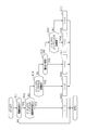
- the vehicle 100 is specifically a two-clutch parallel hybrid vehicle, and is mounted with an engine 110 and a motor generator 112 (corresponding to a rotating electric machine and a generator).
- the output shaft of engine 110 and the output shaft of motor generator 112 are connected via a clutch 114.
- the output shaft of the motor generator 112 is connected to the wheels 119 of the vehicle 100 via a transmission 117 provided with a clutch 116 and a differential 118.
- a high voltage battery 44 is connected to the motor generator 112 via an inverter 120 for motor generator, and power is supplied from the high voltage battery 44 to drive the output shaft.
- the output shaft is driven by the engine 110 to generate power and charge the high voltage battery 44.
- the vehicle 100 is equipped with a low voltage battery 45 whose output voltage is lower than that of the high voltage battery 44.
- the low voltage battery 45 supplies power to the auxiliary machines 104 other than the motor generator 112.
- the high voltage battery 44 and the low voltage battery 45 are connected via the DCDC converter 102.
- the high voltage battery 44 is an assembled battery of lithium ion secondary batteries having an output voltage of 200V
- the low voltage battery 45 is a lead battery having an output voltage of 12V.
- Other batteries may be used as the high voltage battery 44 and the low voltage battery 45.
- a starter 10 is provided for the engine 110, and power is supplied to the starter 10 from a high-voltage battery 44 and a low-voltage battery 45.
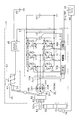
- the configuration of the starter 10 will be described in detail with reference to FIG.
- the vehicle 100 includes a starter 10 and an electronic control device (hereinafter referred to as an engine ECU (Electronic Control Unit) 20) that controls the engine 110.
- the starter 10 includes a motor 30, an inverter 40, a control circuit 41, and an electromagnetic solenoid 50.
- the motor 30 is a three-phase AC rotating machine and includes a rotor 32 and U, V, and W phase stator coils 34U, 34V, and 34W. One end of each of the U, V, W phase stator coils 34U, 34V, 34W is connected to each other at a neutral point.
- a permanent magnet synchronous motor (PMSM: Permanent Magnet Synchronous Motor) is used as the motor 30.
- the connection point of the upper and lower arm switching elements S ⁇ p, S ⁇ n is opposite to the side connected to the neutral point 36 of both ends of the ⁇ phase stator coil 34 ⁇ / b> ⁇ phase terminal).
- a MOSFET Metal-Oxide-Semiconductor Field-Effect Transistor
- a diode D ⁇ # is connected in antiparallel to the switching element S ⁇ #.
- a high voltage battery 44 is connected between a pair of input terminals of the inverter 40 via a capacitor 42. Further, a low voltage battery 45 is connected to one end of a solenoid coil 52 constituting an electromagnetic solenoid 50 (corresponding to a push member) through a DCDC converter 46. The other end of the solenoid coil 52 is grounded.
- the DCDC converter 46 is controlled by the control circuit 41 to perform constant current control with the current I flowing through the solenoid coil 52 as a predetermined current.
- the DCDC converter 46 may perform constant voltage control with the output voltage as a predetermined voltage.
- the DCDC converter 46 is a known chopper circuit, for example.
- the electromagnetic solenoid 50 includes a plunger 54 (movable iron core) in addition to the solenoid coil 52.
- the engine ECU 20 acquires the rotation angle of the crankshaft 70 and the engine rotation speed (NE) by acquiring an output signal from a rotation angle sensor 76 provided for the crankshaft 70 of the engine 110.
- the control circuit 41 (control unit) provided in the starter 10 operates on the inverter 40, that is, the upper and lower arm switching elements S ⁇ p, S ⁇ n.
- the control circuit 41 controls the DCDC converter 46.
- the control circuit 41 acquires the detected values of the V and W phase output currents iv and iw from the current sensors 72V and 72W that detect the output current of the inverter 40.
- the control circuit 41 acquires the detected value of the input voltage VINV from the voltage sensor 74 that detects the input voltage of the inverter 40.
- the engine rotational speed (NE) and the drive request signal (Sig) for the starter 10 are input from the engine ECU 20 to the control circuit 41 of the inverter 40.
- the control circuit 41 controls the starter 10 by adjusting the output current and output voltage of the inverter 40 and the DCDC converter 46 based on the detected value of the engine speed (NE) and the drive request command for the starter 10.
- the control circuit 41 includes a microcomputer including, for example, a CPU (Central Processing Unit), a ROM (Read Only Memory), a RAM (Random Access Memory), and the like.
- the control circuit 41 supplies the motor 30 with a setting unit 41A for setting the starting time of the engine 110 and the starting time set by the setting unit 41A according to the type of the starting factor that generates the starting request for the engine 110.
- a controller 41B that controls at least one of the rotational speed of the motor 30 and the output torque of the motor 30 by setting the current to be performed.
- FIG. 3 is a schematic diagram showing the structure of the starter 10.
- the starter 10 includes a one-way clutch 60, a pinion gear 62, a rotating shaft 64, a stop ring 65, and a shift lever 66.
- the pinion gear 62 is connected to the motor 30 via a one-way clutch 60 and a connecting member 67.
- the one-way clutch 60 transmits the rotational force from the motor 30 to the pinion gear 62 only when the relative rotational speed obtained by subtracting the rotational speed of the pinion gear 62 from the rotational speed of the output shaft 81 of the motor 30 is not negative.
- the one-way clutch 60 is a one-way transmission mechanism that does not transmit rotational force between the motor 30 and the pinion gear 62 when the relative rotational speed is negative.
- the pinion gear 62 is provided coaxially with the output shaft 81 of the motor 30. As shown in FIG. 2, the pinion gear 62 does not mesh with the ring gear 68 at a position indicated by a broken line that meshes with the ring gear 68 that is directly coupled to the crankshaft 70 of the engine 110 (hereinafter referred to as a coupling position (indicated by reference numeral 62a)). It is provided so as to be movable between a position indicated by a solid line (hereinafter referred to as an unconnected position or an initial position).
- the pinion gear 62 is located at the non-connected position.
- the solenoid coil 52 is energized by the power output of the DCDC converter 46, the plunger 54 is moved in a predetermined direction (direction toward the shift lever 66) by the electromagnetic force of the electromagnetic solenoid 50.
- the pinion gear 62 is pushed out from the non-connection position toward the connection position that meshes with the ring gear 68 via the shift lever 66.
- energizing the solenoid coil 52 may be described as driving the electromagnetic solenoid 50.
- the pinion gear 62 is connected to a connecting member 67 (corresponding to a predetermined member) provided coaxially, and a helical spline (illustration is a spiral groove) on the inner periphery of the connecting member 67. Abbreviation) is provided. Further, the output shaft 81 of the motor 30 is provided with a helical tooth that fits with a helical spline provided on the inner periphery of the connecting member 67. The rotation of the output shaft 81 of the motor 30 is transmitted to the connecting member 67 and the pinion gear 62 via the helical spline.
- the pinion gear 62 When the pinion gear 62 moves to the coupling position, the pinion gear 62 can be engaged with the ring gear 68. In a state where the pinion gear 62 is engaged with the ring gear 68, when the pinion gear 62 is rotationally driven by the motor 30, initial rotation is applied to the crankshaft 70 of the engine 110. That is, cranking is performed.
- a stop ring 65 is provided on the rotating shaft 64.
- the electromagnetic solenoid 50 is driven and the pinion gear 62 is pushed out, the pinion gear 62 comes into contact with the stop ring 65 after the meshing of the pinion gear 62 and the ring gear 68 is started.
- a stop ring 65 (corresponding to a second restricting member) abuts on the pinion gear 62, thereby restricting the movement of the pinion gear 62 and fixing the position of the pinion gear 62 to the coupling position.
- a spring 55 (corresponding to an urging member) is connected to the plunger 54.
- the spring 55 applies a biasing force to the plunger 54 to move the plunger 54 in a direction opposite to the moving direction by the electromagnetic solenoid 50 (a direction away from the shift lever 66).
- the energization to the solenoid coil 52 is stopped, and only the urging force by the spring 55 acts on the plunger 54.
- the plunger 54 is moved in a direction away from the shift lever 66.
- the pinion gear 62 is returned from the coupling position to the non-coupling position via the shift lever 66.
- the ring gear 68 is directly connected to the crankshaft 70 as described above. For this reason, the rotation directions of the ring gear 68 and the crankshaft 70 are the same.
- the rotation shaft 64 and the crankshaft 70 are provided such that the axis of the rotation center of the rotation shaft 64 and the axis of the rotation center of the crankshaft 70 are parallel to each other. For this reason, in a state where the pinion gear 62 is engaged with the ring gear 68, the rotation direction of the ring gear 68 is opposite to the rotation direction of the pinion gear 62.
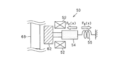
- FIG. 4 shows a pressing force FP by the electromagnetic solenoid 50 acting on the pinion gear 62 and an urging force FB by the spring 55.
- the pushing force FP by the electromagnetic solenoid 50 acts to bring the pinion gear 62 closer to the ring gear 68.
- the urging force FB by the spring 55 acts in the direction opposite to the pushing force FP by the electromagnetic solenoid 50, and acts to separate the pinion gear 62 from the ring gear 68.
- the urging force FB is proportional to the displacement of the pinion gear 62 (plunger 54), and the pushing force FP is inversely proportional to the square of the distance between the solenoid coil 52 and the plunger 54.
- the control circuit 41 of the present embodiment adjusts the current I (solenoid current I) flowing to the electromagnetic solenoid 50 by adjusting the output current of the DCDC converter 46, and is connected to the pinion gear 62 and the pinion gear 62.
- the pushing force FP acting on the members is adjusted.
- the impact between the pinion gear 62 and the ring gear 68 is reduced by reducing the solenoid current I immediately before the pinion gear 62 and the ring gear 68 abut. Further, during the period including the time point when the pinion gear 62 and the stop ring 65 abut, by reducing the solenoid current I, the impact between the pinion gear 62 and the stop ring 65 is reduced, and the plunger 54 and the stopper 56 Reduce the impact.
- a predetermined current is passed as the solenoid current I so that the spring 55 is attached. The force FB is canceled out and the impact between the connecting member 67 connected to the pinion gear 62 and the stopper 82 is reduced.
- FIG. 5 is a flowchart showing the push-out process of the pinion gear 62. This process is performed by the control circuit 41 at predetermined intervals.
- step S01 it is determined whether a starter drive request has occurred.
- the starter drive request is specifically generated in the vehicle 100 when the engine 110 is requested to start.
- the start request of the engine 110 is generated when an acceleration request is generated or when the motor generator 112 generates power in accordance with a decrease in SOC (State Of Charge) of the high voltage battery 44.
- SOC State Of Charge
- the starter drive request is input from the engine ECU 20.
- the starter drive request is not generated (S01: NO)
- the process is terminated.
- step S02 If a starter drive request is generated (S01: YES), it is determined in step S02 whether or not the distance between the pinion gear 62 and the ring gear 68 is a predetermined distance or more. When the distance between the pinion gear 62 and the ring gear 68 is a predetermined distance or more (S02: YES), in step S03, the value of the current flowing to the electromagnetic solenoid 50 is set to I1, and the process ends. .
- step S04 If the distance between the pinion gear 62 and the ring gear 68 is not a predetermined distance or more (S02: NO), it is determined in step S04 whether or not it is a period immediately before the pinion gear 62 and the ring gear 68 come into contact with each other. judge. If it is a period immediately before the pinion gear 62 and the ring gear 68 contact each other (S04: YES), the solenoid current I is decreased by a predetermined amount by setting the solenoid current I to I2 ( ⁇ I1) in step S05. The process is terminated.
- step S06 If it is not the period immediately before the pinion gear 62 and the ring gear 68 contact each other (S04: NO), after the pinion gear 62 and the ring gear 68 contact each other in step S06, the pinion gear 62 is moved to the ring gear 68. It is determined whether or not it is a period for meshing. If it is a period during which the pinion gear 62 is engaged with the ring gear 68 (S06: YES), the solenoid current I is set to I1 in step S07, thereby increasing the solenoid current I by a predetermined amount, and the process ends.
- step S08 If it is not a period for meshing the pinion gear 62 with the ring gear 68 (S06: NO), it is determined whether or not it is a period for the pinion gear 62 to contact the stop ring 65 in step S08. If it is a period during which the pinion gear 62 is in contact with the stop ring 65 (S08: YES), the solenoid current I is reduced to a predetermined amount by setting the solenoid current I to I3 ( ⁇ I1) in step S09. finish.
- step S10 the solenoid current I is set to I4 (I1> I2> I4> I3), and the process ends.
- FIG. 6 is a flowchart showing the push-back process of the pinion gear 62. This process is performed by the control circuit 41 at predetermined intervals.
- step S21 it is determined whether or not it is a period after the end of cranking.
- the period after the end of cranking is a period after the starter drive request is stopped until the pinion gear 62 is returned to the initial position. If it is not the period after the end of cranking (S21: NO), the process ends.
- step S22 If it is a period after the end of cranking (S21: YES), it is determined in step S22 whether or not the push-back process of the pinion gear 62 has been started. If the pinion gear 62 is not being pushed back (S22: NO), it is determined in step S23 whether or not the temporal change amount (dNE / dt) of the engine rotation speed is less than a predetermined value. When the engine speed change over time is equal to or greater than the predetermined value (S23: NO), the engagement of the pinion gear 62 and the ring gear 68 is maintained by setting the solenoid current I to I4 in step S24. When the temporal change amount of the engine rotation speed is less than the predetermined value (S23: YES), the push-back process of the pinion gear 62 is started in step S25, and the solenoid current I is set to 0 in step S26.
- step S27 If the push-back process of the pinion gear 62 has been started (S22: YES), it is determined in step S27 whether or not it is a period immediately before the pinion gear 62 returns to the initial position. If it is not the period immediately before the pinion gear 62 returns to the initial position (S27: NO), the solenoid current I is set to 0 in step S29, and the process ends. When it is a period immediately before the pinion gear 62 returns to the initial position (S27: YES), in step S28, the solenoid current I is set to I5 (I4> I5), so that the predetermined current I5 flows through the electromagnetic solenoid 50, The process ends.
- FIG. 7 is a timing chart showing a change in the current I flowing through the electromagnetic solenoid 50 and the position (displacement) of the pinion gear 62 when the control shown in FIGS.
- the solenoid current I is changed from 0 to I1.
- the solenoid current I is set to I1
- the pinion gear 62 approaches the ring gear 68 while being accelerated.
- the distance between the pinion gear 62 and the ring gear 68 becomes a predetermined distance, and a period immediately before the pinion gear 62 and the ring gear 68 come into contact with each other, so that the solenoid current I decreases from I1 to I2.
- the pushing force FP acting on the pinion gear 62 becomes weaker than the biasing force FB, so that the moving speed of the pinion gear 62 in the axial direction decreases.
- the moving speed of the pinion gear 62 becomes almost zero, and the solenoid current I increases from I2 to I1 at time t2, which is a time immediately before the pinion gear 62 and the ring gear 68 come into contact with each other.
- the pushing force FP acting on the pinion gear 62 becomes stronger than the urging force FB
- the pinion gear 62 is brought into contact with the ring gear 68
- the engagement between the pinion gear 62 and the ring gear 68 starts at time t3. Is done.
- the pinion gear 62 is pushed into the ring gear 68 so that the tooth portion of the pinion gear 62 is inserted into the groove portion of the ring gear 68.
- the solenoid current I is set to I3 at time t4, which is the time immediately before the pinion gear 62 and the stop ring 65 abut. Thereby, the pushing force FP acting on the pinion gear 62 and the sum of the urging force FB and the frictional force become substantially equal, and the acceleration of the pinion gear 62 is weakened. Thereafter, at time t5, the pinion gear 62 comes into contact with the stop ring 65, and the pinion gear 62 is brought into the coupling position.
- the solenoid current I is set to I4, and the pinion gear 62 and the ring gear 68 are fixed to the coupling position. And the cranking is carried out.
- cranking is completed, the starter drive request is stopped, and the solenoid current I is set to 0 when the amount of change in the engine rotational speed with time becomes less than a predetermined value.
- the solenoid current I is set to 0 when the amount of change in the engine rotational speed with time becomes less than a predetermined value.
- the solenoid current I is set to I5 at time t11, which is a time immediately before the pinion gear 62 returns to the initial position. Thereby, the pushing force FP becomes stronger than the urging force FB, and the moving speed of the pinion gear 62 in the axial direction is reduced. Thereafter, at time t12, the pinion gear 62 is set to the initial position, and the connecting member 67 is brought into contact with the stopper 82. With the above operation, it is possible to mitigate the impact when pushing the pinion gear 62 to the ring gear 68 and the impact when pushing the pinion gear 62 back from the ring gear 68 to the initial position.
- the engine 110 is set to have a start time depending on the type of start factor that generates a start request for the engine 110. Furthermore, the current supplied to the motor 30 is set based on the starting time, thereby controlling at least one of the rotational speed and the output torque of the motor 30.
- a request for acceleration of vehicle 100 is included as a type of start factor that generates a start request for engine 110.
- a power generation request in motor generator 112 accompanying a decrease in SOC (charge rate) of high voltage battery 44 is included.
- an operation request for a heating device (not shown) that warms the interior of vehicle 100 using heat generated in engine 110 as a heat source is included.
- a start request for engine 110 accompanying a decrease in the temperature of cooling water of engine 110 is included.
- the engine start accompanying the acceleration request of the vehicle 100 requires a responsiveness as compared with other starting factors.
- the engine 110 is set to have a shorter start time when the engine 110 is started when the vehicle 100 is requested to be accelerated than when the engine 110 is started due to another start factor. Further, when the engine 110 is started in response to the acceleration request of the vehicle 100, the start time is set based on the accelerator operation amount and the time change amount of the accelerator operation amount as the acceleration request.
- FIG. 8 shows a map showing correspondence between the accelerator operation amount (%), the time change amount of the accelerator operation amount (% / sec), and the engine start time (msec).
- the engine start time is set shorter as the accelerator operation amount is larger. Further, the engine start time is set shorter as the time change amount of the accelerator operation amount is larger.
- the accelerator operation amount is expressed as a ratio of the actual value to the maximum value of the operation amount.
- the control for reducing the rotation speed of the motor 30 and the control for reducing the output torque are performed. By performing such control, it is possible to suppress the generation of noise when the starter 10 is driven.
- FIG. 9 is a timing chart showing the motor rotation speed and engine rotation speed when the starter is driven (cranking).
- the combustion stroke of the engine 110 which is a four-stroke engine, is composed of four strokes: an intake stroke, a compression stroke, a combustion stroke, and an exhaust stroke.
- starter driving cranking
- the combustion stroke is started and the engine 110 is started.
- the piston is stopped near the top dead center in any of the cylinders constituting the engine 110. Thereby, the startability of engine 110 improves.
- FIG. 10 is a timing chart showing the rotation speed of the motor 30 and the engine rotation speed when the starter is driven when the set start time is short and the output torque of the motor 30 is large.
- cranking is completed until the expansion stroke (compression stroke in FIG. 11) substantially starts, and the relative rotation speed of the motor 30 with respect to the crankshaft 70 is maintained negative. Then, control for preventing re-engagement of the one-way clutch 60 is performed. Specifically, by increasing the output torque of the motor 30, cranking by torque transmission from the pinion gear 62 to the ring gear 68 is completed until the expansion stroke (compression stroke in FIG. 11) substantially starts. .
- completing the cranking means giving the crankshaft 70 energy necessary for completing the compression stroke in FIG. 11 and shifting to the combustion stroke. Thereby, it can transfer to a combustion stroke, maintaining the relative rotational speed of the motor 30 with respect to the rotational speed of the crankshaft 70 negative. That is, it is possible to suppress the generation of noise in the starter 10 and to shorten the life of the starter 10.
- FIG. 12 is a flowchart showing a process for setting the start time of the engine 110 and a process for setting the output torque and rotation speed of the motor 30. This process is performed at predetermined intervals in the control circuit 41 functionally including the “control unit 41B” and the “setting unit 41A”. The processing may be shared between the engine ECU 20 and the control circuit 41.
- step S31 it is determined whether an engine start request has occurred. If no engine start request is generated (S31: NO), the process is terminated. If an engine start request has occurred (S31: YES), it is determined in step S32 whether or not the engine start request is a request for acceleration of the vehicle 100.
- the engine start request is caused by a plurality of start factors, and the start factor includes a request for acceleration of the vehicle 100, the engine start request is an acceleration request of the vehicle 100. It is determined that this is a problem.
- step S34 the setting unit 41A of the control circuit 41 sets the start time of the engine 110 based on the accelerator operation amount, the time change amount of the accelerator operation amount, and the map shown in FIG.
- a start time is set based on the type of start factor in step S35.
- the setting unit 41A sets the start time based on the start factor having the shortest start time among the plurality of start factors.
- the control unit 41B of the control circuit 41 sets the current supplied to the motor 30 based on the start time of the engine 110 set in step S34 or step S35, whereby the output torque and rotation of the motor 30 are set.
- Set the speed Specifically, the control unit 41B sets the rotation speed of the motor 30 to be smaller and sets the output torque to be smaller as the starting time is longer. In addition, you may set either one of the rotational speed of the motor 30, and an output torque small, so that starting time is long.
- Step S37 it is determined whether or not the output torque set in Step S36 is larger than a predetermined value set in advance. If the output torque is greater than the predetermined value (S37: YES), the output torque is reset in step S38. Specifically, in any of the cylinders constituting the engine 110, the energy required to complete the compression stroke can be applied to the crankshaft 70 until the expansion stroke without combustion is substantially started. Increase the output torque and reset. Thereby, it can transfer to a combustion stroke, maintaining the relative rotational speed of the motor 30 with respect to the rotational speed of the crankshaft 70 negative.
- step S39 After resetting the output torque in step S38, and when the output torque is equal to or less than a predetermined value in the determination in step S37 (S37: NO), in step S39, the start time is compared with a predetermined threshold time set in advance. To do. When the starting time is equal to or longer than the threshold time (S39: YES), the setting unit 41A sets in step S40 so as to perform noise reduction control (control shown in FIG. 5) when the pinion gear 62 is pushed out. Exit. If the start time is shorter than the threshold time (S39: NO), the noise reduction control (control shown in FIG. 5) when pushing the pinion gear 62 is set to be omitted (S41), and the process is terminated.
- the silent control when pushing out the pinion gear 62 is omitted specifically means that the processing of steps S02 to S09 shown in FIG. 5 is omitted, and a drive request for the starter 10 is generated. After that, the solenoid current I is uniformly set to I1 until the pinion gear 62 and the stop ring 65 contact each other.
- the control in steps S08 and S09 is performed when the noise reduction control (control shown in FIG. 5) is performed when the pinion gear 62 is pushed out in step S40. May be omitted. That is, when the pinion gear 62 and the ring gear 68 come into contact with each other, only control for reducing the solenoid current I from I1 to I2 is performed in a period in which the distance between the pinion gear 62 and the ring gear 68 is within a predetermined range. It is good.
- step S40 when the start time is equal to or longer than the threshold time (S39: YES), in step S40, when the silence control at the time of pushing out the pinion gear 62 (control shown in FIG. 5) is performed, step S04, The control in S05 may be omitted. That is, when the pinion gear 62 and the stop ring 65 come into contact with each other, only control for reducing the solenoid current I from I1 to I3 is performed in a period in which the distance between the pinion gear 62 and the stop ring 65 is within a predetermined range. It is good.
- the starter 10 can be secured and the starter 10 can be kept quiet by performing the noise reduction process when the pinion gear 62 is pushed out. It becomes possible.
- the setting unit 41A sets the start time according to the type of the start factor, and the control unit 41B controls at least one of the rotational speed and the output torque of the motor 30 based on the start time.
- the engine start can be prioritized by increasing at least one of the rotational speed and output torque of the motor 30.
- priority can be given to the quietness of the starter 10 by reducing at least one of the rotational speed of the motor 30 and an output torque.
- a specific example of the start command that requires an emergency is a start command that accompanies an acceleration request for the vehicle 100.
- the setting unit 41A improves the startability of the engine 110 by setting the start time shorter than the start command other than the start command accompanying the acceleration request. can do.
- the setting unit 41A sets the start time based on the accelerator operation amount (throttle opening rate) and the time change amount of the accelerator operation amount, so that the engine 110 can be started according to the degree of urgency. become.
- the start command having a lower degree of urgency than the acceleration request is specifically a start command associated with a decrease in the SOC of the high voltage battery 44, a start command associated with a heating device operation request, and an engine.
- 110 is a start command accompanying a decrease in the coolant temperature of 110.
- the control unit 41B when the start time is long, performs at least one of the control for reducing the rotation speed of the motor 30 or the control for reducing the output torque of the motor 30, thereby reducing noise. realizable.
- the one-way clutch 60 is at a timing when the relative rotational speed becomes negative ⁇ 0.
- a big force is added to.
- this force causes noise and shortens the life of the starter 10. Therefore, the output torque is increased so that the cranking is completed before the setting unit 41A substantially starts the expansion stroke in any cylinder constituting the engine 110, and the meshing between the ring gear 68 and the pinion gear 62 is performed. Release it.
- the relative rotational speed of the pinion gear 62 with respect to the rotational speed of the crankshaft 70 is prevented from temporarily becoming negative. Thereby, generation
- the motor 30 constituting the starter 10 is supplied with electric power from the same secondary battery (high voltage battery 44) as the motor generator 112 that is a power source of the vehicle 100, so that the output torque of the motor 30 is increased. Can be improved. Thereby, it is possible to shorten the start time of the engine 110.
- the DCDC converter 46 may be omitted, and the function of adjusting the current I flowing through the solenoid coil 52 may be omitted.
- a relay switch may be provided between the low voltage battery 45 and the solenoid coil 52, and the control circuit 41 may open and close the relay switch.
- step S04 in FIG. 5 may be omitted, and the pinion gear 62 may be brought into contact with the ring gear 68 without being decelerated. Similarly, in step S08, the pinion gear 62 may be brought into contact with the stop ring 65 without being decelerated.
- step S23 in FIG. 6 may be omitted, and the pinion gear 62 may be pushed back simultaneously with the end of cranking.
- the start time of the engine 110 is set based on the accelerator operation amount and the time change amount of the accelerator operation amount, but this may be changed. In other words, the start time of the engine 110 may be set based only on the time change amount of the accelerator operation amount. Moreover, it is good also as a structure which sets the starting time of the engine 110 based only on the amount of accelerator operation.
- steps S37 and S38 in FIG. 12 when the output torque is greater than a predetermined value, the output torque is further increased, so that an expansion stroke without a combustion stroke is substantially started in any of the cylinders constituting the engine 110. Up to this point, the cranking has been completed.
- cranking is performed until the expansion stroke without any combustion stroke is substantially started in any of the cylinders constituting the engine 110.
- the configuration may be completed. Even if it is a case where it changes to such a structure, it can suppress that the relative rotational speed of the pinion gear 62 with respect to the crankshaft 70 (ring gear 68) becomes 0-> negative. In other words, this makes it possible to shift to the combustion stroke while maintaining the relative rotational speed of the motor 30 with respect to the rotational speed of the crankshaft 70 negative.
Landscapes
- Engineering & Computer Science (AREA)
- Mechanical Engineering (AREA)
- Chemical & Material Sciences (AREA)
- Combustion & Propulsion (AREA)
- General Engineering & Computer Science (AREA)
- Transportation (AREA)
- Automation & Control Theory (AREA)
- Power Engineering (AREA)
- Hybrid Electric Vehicles (AREA)
- Control Of Vehicle Engines Or Engines For Specific Uses (AREA)
Priority Applications (2)
| Application Number | Priority Date | Filing Date | Title |
|---|---|---|---|
| DE112017000467.5T DE112017000467T5 (de) | 2016-01-21 | 2017-01-20 | Anlasser |
| US16/071,945 US10533528B2 (en) | 2016-01-21 | 2017-01-20 | Starter |
Applications Claiming Priority (2)
| Application Number | Priority Date | Filing Date | Title |
|---|---|---|---|
| JP2016-009576 | 2016-01-21 | ||
| JP2016009576A JP6399005B2 (ja) | 2016-01-21 | 2016-01-21 | スタータ |
Publications (1)
| Publication Number | Publication Date |
|---|---|
| WO2017126685A1 true WO2017126685A1 (ja) | 2017-07-27 |
Family
ID=59362126
Family Applications (1)
| Application Number | Title | Priority Date | Filing Date |
|---|---|---|---|
| PCT/JP2017/002002 Ceased WO2017126685A1 (ja) | 2016-01-21 | 2017-01-20 | スタータ |
Country Status (4)
| Country | Link |
|---|---|
| US (1) | US10533528B2 (https=) |
| JP (1) | JP6399005B2 (https=) |
| DE (1) | DE112017000467T5 (https=) |
| WO (1) | WO2017126685A1 (https=) |
Families Citing this family (7)
| Publication number | Priority date | Publication date | Assignee | Title |
|---|---|---|---|---|
| JP6764356B2 (ja) * | 2017-03-02 | 2020-09-30 | 株式会社デンソー | 始動装置、回転電機、及び始動用電動機 |
| JP6333442B1 (ja) * | 2017-05-18 | 2018-05-30 | 三菱電機株式会社 | エンジン始動装置 |
| JP7052387B2 (ja) * | 2018-02-06 | 2022-04-12 | 株式会社ジェイテクト | 電動ギヤポンプ |
| US11168657B2 (en) * | 2020-02-28 | 2021-11-09 | Ford Global Technologies, Llc | Methods and system for a stop/start vehicle |
| US11345326B2 (en) * | 2020-03-25 | 2022-05-31 | Ford Global Technologies, Llc | Methods and system for starting an internal combustion engine |
| US11473544B2 (en) * | 2021-01-05 | 2022-10-18 | Ford Global Technologies, Llc | Methods and system for starting an engine |
| JP7816215B2 (ja) * | 2023-02-27 | 2026-02-18 | トヨタ自動車株式会社 | 強化学習方法及びモータコントロールユニット |
Citations (14)
| Publication number | Priority date | Publication date | Assignee | Title |
|---|---|---|---|---|
| JP2001227439A (ja) * | 2000-02-15 | 2001-08-24 | Mitsubishi Electric Corp | 始動電動機 |
| JP2002122059A (ja) * | 2000-08-10 | 2002-04-26 | Denso Corp | スタータ制御方法 |
| JP2006233977A (ja) * | 2006-05-26 | 2006-09-07 | Toyota Motor Corp | 車両の制御装置およびモータジェネレータユニット |
| JP2007211713A (ja) * | 2006-02-10 | 2007-08-23 | Toyota Motor Corp | 車両の異常報知装置 |
| JP2007230321A (ja) * | 2006-02-28 | 2007-09-13 | Toyota Motor Corp | 車両用空調装置 |
| JP2007231786A (ja) * | 2006-02-28 | 2007-09-13 | Toyota Motor Corp | 内燃機関の自動停止装置及びこの自動停止装置を備えた自動車用内燃機関 |
| JP2010265878A (ja) * | 2009-05-18 | 2010-11-25 | Denso Corp | 内燃機関の制御装置 |
| WO2012063299A1 (ja) * | 2010-11-08 | 2012-05-18 | トヨタ自動車株式会社 | ハイブリッド自動車 |
| JP2013043572A (ja) * | 2011-08-24 | 2013-03-04 | Toyota Motor Corp | 車両の制御装置 |
| WO2013038492A1 (ja) * | 2011-09-13 | 2013-03-21 | トヨタ自動車株式会社 | 車両の制御装置および制御方法 |
| JP2013144534A (ja) * | 2011-12-16 | 2013-07-25 | Nippon Soken Inc | 内燃機関の始動制御装置 |
| JP2014224538A (ja) * | 2014-07-22 | 2014-12-04 | 日立オートモティブシステムズ株式会社 | スタータ |
| JP2015104985A (ja) * | 2013-11-29 | 2015-06-08 | トヨタ自動車株式会社 | ハイブリッド車両 |
| JP2015231769A (ja) * | 2014-06-09 | 2015-12-24 | トヨタ自動車株式会社 | 内燃機関の始動装置 |
Family Cites Families (14)
| Publication number | Priority date | Publication date | Assignee | Title |
|---|---|---|---|---|
| FR2749451B1 (fr) | 1996-06-04 | 1998-08-21 | Valeo Equip Electr Moteur | Procede et dispositif de commande de demarreur de vehicule automobile |
| DE19841752A1 (de) * | 1998-09-11 | 2000-03-16 | Bayerische Motoren Werke Ag | Verfahren zum Starten eines Verbrennungsmotors |
| JP3541875B2 (ja) | 1999-01-19 | 2004-07-14 | 三菱自動車工業株式会社 | ハイブリッド車のエンジン始動装置 |
| JP2012144172A (ja) | 2011-01-13 | 2012-08-02 | Toyota Motor Corp | ハイブリッド車両の制御装置 |
| GB2490109B (en) * | 2011-04-14 | 2016-10-12 | Ford Global Tech Llc | A method and apparatus for controlling an engine of a motor vehicle |
| JP5854315B2 (ja) | 2011-09-14 | 2016-02-09 | 日産自動車株式会社 | ハイブリッド車両の制御装置 |
| US9068546B2 (en) * | 2012-05-04 | 2015-06-30 | Ford Global Technologies, Llc | Methods and systems for engine cranking |
| JP5983581B2 (ja) | 2013-10-28 | 2016-08-31 | 株式会社デンソー | システム、及びシステムの制御装置 |
| JP6090119B2 (ja) | 2013-11-11 | 2017-03-08 | 株式会社デンソー | エンジンの始動装置 |
| GB2523080A (en) * | 2014-02-12 | 2015-08-19 | Ford Global Tech Llc | An apparatus and method for starting an engine |
| JP6364974B2 (ja) * | 2014-06-04 | 2018-08-01 | 株式会社デンソー | エンジン始動装置 |
| JP6247604B2 (ja) | 2014-06-24 | 2017-12-13 | 日本航空電子工業株式会社 | 防水コネクタ |
| JP6589696B2 (ja) * | 2016-03-03 | 2019-10-16 | 株式会社デンソー | エンジン始動システム |
| JP6665734B2 (ja) * | 2016-08-30 | 2020-03-13 | 株式会社デンソー | エンジン始動装置 |
-
2016
- 2016-01-21 JP JP2016009576A patent/JP6399005B2/ja not_active Expired - Fee Related
-
2017
- 2017-01-20 WO PCT/JP2017/002002 patent/WO2017126685A1/ja not_active Ceased
- 2017-01-20 DE DE112017000467.5T patent/DE112017000467T5/de not_active Ceased
- 2017-01-20 US US16/071,945 patent/US10533528B2/en active Active
Patent Citations (14)
| Publication number | Priority date | Publication date | Assignee | Title |
|---|---|---|---|---|
| JP2001227439A (ja) * | 2000-02-15 | 2001-08-24 | Mitsubishi Electric Corp | 始動電動機 |
| JP2002122059A (ja) * | 2000-08-10 | 2002-04-26 | Denso Corp | スタータ制御方法 |
| JP2007211713A (ja) * | 2006-02-10 | 2007-08-23 | Toyota Motor Corp | 車両の異常報知装置 |
| JP2007230321A (ja) * | 2006-02-28 | 2007-09-13 | Toyota Motor Corp | 車両用空調装置 |
| JP2007231786A (ja) * | 2006-02-28 | 2007-09-13 | Toyota Motor Corp | 内燃機関の自動停止装置及びこの自動停止装置を備えた自動車用内燃機関 |
| JP2006233977A (ja) * | 2006-05-26 | 2006-09-07 | Toyota Motor Corp | 車両の制御装置およびモータジェネレータユニット |
| JP2010265878A (ja) * | 2009-05-18 | 2010-11-25 | Denso Corp | 内燃機関の制御装置 |
| WO2012063299A1 (ja) * | 2010-11-08 | 2012-05-18 | トヨタ自動車株式会社 | ハイブリッド自動車 |
| JP2013043572A (ja) * | 2011-08-24 | 2013-03-04 | Toyota Motor Corp | 車両の制御装置 |
| WO2013038492A1 (ja) * | 2011-09-13 | 2013-03-21 | トヨタ自動車株式会社 | 車両の制御装置および制御方法 |
| JP2013144534A (ja) * | 2011-12-16 | 2013-07-25 | Nippon Soken Inc | 内燃機関の始動制御装置 |
| JP2015104985A (ja) * | 2013-11-29 | 2015-06-08 | トヨタ自動車株式会社 | ハイブリッド車両 |
| JP2015231769A (ja) * | 2014-06-09 | 2015-12-24 | トヨタ自動車株式会社 | 内燃機関の始動装置 |
| JP2014224538A (ja) * | 2014-07-22 | 2014-12-04 | 日立オートモティブシステムズ株式会社 | スタータ |
Also Published As
| Publication number | Publication date |
|---|---|
| JP2017129075A (ja) | 2017-07-27 |
| US10533528B2 (en) | 2020-01-14 |
| JP6399005B2 (ja) | 2018-10-03 |
| US20190040831A1 (en) | 2019-02-07 |
| DE112017000467T5 (de) | 2018-09-27 |
Similar Documents
| Publication | Publication Date | Title |
|---|---|---|
| JP6399005B2 (ja) | スタータ | |
| JP5875664B1 (ja) | エンジン始動制御装置およびエンジン始動制御方法 | |
| US10000205B2 (en) | Fail-safe control apparatus for hybrid vehicles | |
| RU2641405C2 (ru) | Гибридное транспортное средство | |
| US8554453B2 (en) | Device and method for controlling starter, and vehicle | |
| US8573174B2 (en) | Engine starting device and engine starting method | |
| US8870710B2 (en) | Vehicle drive control system | |
| US8267061B2 (en) | Engine starting device and engine starting method | |
| KR102406142B1 (ko) | 마일드 하이브리드 차량의 제어 방법 | |
| JP2012215076A (ja) | 内燃機関の制御装置、およびそれを搭載する車両 | |
| JP2017203435A (ja) | エンジンの始動制御システム | |
| US9109567B2 (en) | Starter control device, starter control method, and engine starting device | |
| JP2021059265A (ja) | ハイブリッド車両の充電制御方法及びハイブリッド車両の充電制御装置 | |
| US11719211B2 (en) | Vehicle engine starting method, series hybrid vehicle, and vehicle engine starting device | |
| US8706387B2 (en) | Control device and control method for engine, and vehicle | |
| JP6414553B2 (ja) | スタータ | |
| JP6891486B2 (ja) | ハイブリッド車両の駆動制御装置 | |
| US12281623B2 (en) | Drive control system | |
| KR20230040424A (ko) | 하이브리드 차량의 제어 방법 및 그 제어 장치 | |
| JP3687368B2 (ja) | 車両の始動制御装置 | |
| JP7750102B2 (ja) | 車両の制御装置 | |
| WO2012131845A1 (ja) | スタータの制御装置および制御方法、ならびに車両 | |
| JP5768628B2 (ja) | 内燃機関のスタータ、それを備える内燃機関、内燃機関のスタータの制御方法、及びアイドリングストップシステムの制御方法 | |
| JP2018127953A (ja) | エンジン始動装置 | |
| EP3315748B1 (en) | Vehicle-mounted control device |
Legal Events
| Date | Code | Title | Description |
|---|---|---|---|
| 121 | Ep: the epo has been informed by wipo that ep was designated in this application |
Ref document number: 17741562 Country of ref document: EP Kind code of ref document: A1 |
|
| WWE | Wipo information: entry into national phase |
Ref document number: 112017000467 Country of ref document: DE |
|
| 122 | Ep: pct application non-entry in european phase |
Ref document number: 17741562 Country of ref document: EP Kind code of ref document: A1 |