WO2017126516A1 - Dispositif de commande de capteur - Google Patents
Dispositif de commande de capteur Download PDFInfo
- Publication number
- WO2017126516A1 WO2017126516A1 PCT/JP2017/001452 JP2017001452W WO2017126516A1 WO 2017126516 A1 WO2017126516 A1 WO 2017126516A1 JP 2017001452 W JP2017001452 W JP 2017001452W WO 2017126516 A1 WO2017126516 A1 WO 2017126516A1
- Authority
- WO
- WIPO (PCT)
- Prior art keywords
- sensor
- particulate matter
- amount
- determination
- sensor control
- Prior art date
Links
- 239000013618 particulate matter Substances 0.000 claims abstract description 235
- 238000000034 method Methods 0.000 claims abstract description 107
- 230000008929 regeneration Effects 0.000 claims abstract description 69
- 238000011069 regeneration method Methods 0.000 claims abstract description 69
- 238000001514 detection method Methods 0.000 claims abstract description 53
- 238000010438 heat treatment Methods 0.000 claims abstract description 29
- 230000005856 abnormality Effects 0.000 claims description 35
- 238000002485 combustion reaction Methods 0.000 claims description 14
- 230000002159 abnormal effect Effects 0.000 claims description 2
- 239000000758 substrate Substances 0.000 abstract description 33
- 238000009413 insulation Methods 0.000 abstract 3
- 238000010586 diagram Methods 0.000 description 7
- 230000001186 cumulative effect Effects 0.000 description 5
- 238000002347 injection Methods 0.000 description 4
- 239000007924 injection Substances 0.000 description 4
- 230000000694 effects Effects 0.000 description 3
- 239000000446 fuel Substances 0.000 description 3
- 238000005336 cracking Methods 0.000 description 2
- 238000005516 engineering process Methods 0.000 description 2
- 238000002844 melting Methods 0.000 description 2
- 230000008018 melting Effects 0.000 description 2
- XLYOFNOQVPJJNP-UHFFFAOYSA-N water Substances O XLYOFNOQVPJJNP-UHFFFAOYSA-N 0.000 description 2
- 238000001816 cooling Methods 0.000 description 1
- 238000003745 diagnosis Methods 0.000 description 1
- 238000001035 drying Methods 0.000 description 1
- 230000006870 function Effects 0.000 description 1
- 238000010030 laminating Methods 0.000 description 1
- 239000002245 particle Substances 0.000 description 1
- 230000001681 protective effect Effects 0.000 description 1
- 239000000126 substance Substances 0.000 description 1
- 238000011144 upstream manufacturing Methods 0.000 description 1
Images


Classifications
-
- F—MECHANICAL ENGINEERING; LIGHTING; HEATING; WEAPONS; BLASTING
- F01—MACHINES OR ENGINES IN GENERAL; ENGINE PLANTS IN GENERAL; STEAM ENGINES
- F01N—GAS-FLOW SILENCERS OR EXHAUST APPARATUS FOR MACHINES OR ENGINES IN GENERAL; GAS-FLOW SILENCERS OR EXHAUST APPARATUS FOR INTERNAL COMBUSTION ENGINES
- F01N3/00—Exhaust or silencing apparatus having means for purifying, rendering innocuous, or otherwise treating exhaust
- F01N3/02—Exhaust or silencing apparatus having means for purifying, rendering innocuous, or otherwise treating exhaust for cooling, or for removing solid constituents of, exhaust
-
- F—MECHANICAL ENGINEERING; LIGHTING; HEATING; WEAPONS; BLASTING
- F02—COMBUSTION ENGINES; HOT-GAS OR COMBUSTION-PRODUCT ENGINE PLANTS
- F02D—CONTROLLING COMBUSTION ENGINES
- F02D41/00—Electrical control of supply of combustible mixture or its constituents
- F02D41/02—Circuit arrangements for generating control signals
- F02D41/14—Introducing closed-loop corrections
- F02D41/1438—Introducing closed-loop corrections using means for determining characteristics of the combustion gases; Sensors therefor
- F02D41/1444—Introducing closed-loop corrections using means for determining characteristics of the combustion gases; Sensors therefor characterised by the characteristics of the combustion gases
- F02D41/1466—Introducing closed-loop corrections using means for determining characteristics of the combustion gases; Sensors therefor characterised by the characteristics of the combustion gases the characteristics being a soot concentration or content
-
- F—MECHANICAL ENGINEERING; LIGHTING; HEATING; WEAPONS; BLASTING
- F02—COMBUSTION ENGINES; HOT-GAS OR COMBUSTION-PRODUCT ENGINE PLANTS
- F02D—CONTROLLING COMBUSTION ENGINES
- F02D41/00—Electrical control of supply of combustible mixture or its constituents
- F02D41/02—Circuit arrangements for generating control signals
- F02D41/14—Introducing closed-loop corrections
- F02D41/1438—Introducing closed-loop corrections using means for determining characteristics of the combustion gases; Sensors therefor
- F02D41/1493—Details
- F02D41/1494—Control of sensor heater
-
- G—PHYSICS
- G01—MEASURING; TESTING
- G01N—INVESTIGATING OR ANALYSING MATERIALS BY DETERMINING THEIR CHEMICAL OR PHYSICAL PROPERTIES
- G01N15/00—Investigating characteristics of particles; Investigating permeability, pore-volume or surface-area of porous materials
- G01N15/06—Investigating concentration of particle suspensions
- G01N15/0656—Investigating concentration of particle suspensions using electric, e.g. electrostatic methods or magnetic methods
-
- F—MECHANICAL ENGINEERING; LIGHTING; HEATING; WEAPONS; BLASTING
- F01—MACHINES OR ENGINES IN GENERAL; ENGINE PLANTS IN GENERAL; STEAM ENGINES
- F01N—GAS-FLOW SILENCERS OR EXHAUST APPARATUS FOR MACHINES OR ENGINES IN GENERAL; GAS-FLOW SILENCERS OR EXHAUST APPARATUS FOR INTERNAL COMBUSTION ENGINES
- F01N11/00—Monitoring or diagnostic devices for exhaust-gas treatment apparatus, e.g. for catalytic activity
-
- F—MECHANICAL ENGINEERING; LIGHTING; HEATING; WEAPONS; BLASTING
- F01—MACHINES OR ENGINES IN GENERAL; ENGINE PLANTS IN GENERAL; STEAM ENGINES
- F01N—GAS-FLOW SILENCERS OR EXHAUST APPARATUS FOR MACHINES OR ENGINES IN GENERAL; GAS-FLOW SILENCERS OR EXHAUST APPARATUS FOR INTERNAL COMBUSTION ENGINES
- F01N2240/00—Combination or association of two or more different exhaust treating devices, or of at least one such device with an auxiliary device, not covered by indexing codes F01N2230/00 or F01N2250/00, one of the devices being
- F01N2240/16—Combination or association of two or more different exhaust treating devices, or of at least one such device with an auxiliary device, not covered by indexing codes F01N2230/00 or F01N2250/00, one of the devices being an electric heater, i.e. a resistance heater
-
- F—MECHANICAL ENGINEERING; LIGHTING; HEATING; WEAPONS; BLASTING
- F01—MACHINES OR ENGINES IN GENERAL; ENGINE PLANTS IN GENERAL; STEAM ENGINES
- F01N—GAS-FLOW SILENCERS OR EXHAUST APPARATUS FOR MACHINES OR ENGINES IN GENERAL; GAS-FLOW SILENCERS OR EXHAUST APPARATUS FOR INTERNAL COMBUSTION ENGINES
- F01N2560/00—Exhaust systems with means for detecting or measuring exhaust gas components or characteristics
- F01N2560/05—Exhaust systems with means for detecting or measuring exhaust gas components or characteristics the means being a particulate sensor
-
- F—MECHANICAL ENGINEERING; LIGHTING; HEATING; WEAPONS; BLASTING
- F01—MACHINES OR ENGINES IN GENERAL; ENGINE PLANTS IN GENERAL; STEAM ENGINES
- F01N—GAS-FLOW SILENCERS OR EXHAUST APPARATUS FOR MACHINES OR ENGINES IN GENERAL; GAS-FLOW SILENCERS OR EXHAUST APPARATUS FOR INTERNAL COMBUSTION ENGINES
- F01N2560/00—Exhaust systems with means for detecting or measuring exhaust gas components or characteristics
- F01N2560/20—Sensor having heating means
-
- F—MECHANICAL ENGINEERING; LIGHTING; HEATING; WEAPONS; BLASTING
- F01—MACHINES OR ENGINES IN GENERAL; ENGINE PLANTS IN GENERAL; STEAM ENGINES
- F01N—GAS-FLOW SILENCERS OR EXHAUST APPARATUS FOR MACHINES OR ENGINES IN GENERAL; GAS-FLOW SILENCERS OR EXHAUST APPARATUS FOR INTERNAL COMBUSTION ENGINES
- F01N2900/00—Details of electrical control or of the monitoring of the exhaust gas treating apparatus
- F01N2900/04—Methods of control or diagnosing
- F01N2900/0422—Methods of control or diagnosing measuring the elapsed time
-
- Y—GENERAL TAGGING OF NEW TECHNOLOGICAL DEVELOPMENTS; GENERAL TAGGING OF CROSS-SECTIONAL TECHNOLOGIES SPANNING OVER SEVERAL SECTIONS OF THE IPC; TECHNICAL SUBJECTS COVERED BY FORMER USPC CROSS-REFERENCE ART COLLECTIONS [XRACs] AND DIGESTS
- Y02—TECHNOLOGIES OR APPLICATIONS FOR MITIGATION OR ADAPTATION AGAINST CLIMATE CHANGE
- Y02T—CLIMATE CHANGE MITIGATION TECHNOLOGIES RELATED TO TRANSPORTATION
- Y02T10/00—Road transport of goods or passengers
- Y02T10/10—Internal combustion engine [ICE] based vehicles
- Y02T10/12—Improving ICE efficiencies
Definitions
- the present disclosure relates to a sensor control technique for detecting particulate matter (PM) in an exhaust passage of an internal combustion engine.
- a filter device for collecting particulate matter is provided in the exhaust passage from the engine.
- a particulate matter detection sensor is provided on the downstream side of the filter device to determine whether there is an abnormality such as cracking or melting of the filter device.
- Patent Document 1 discloses the following technique in order to accurately grasp the amount of particulate matter reaching the sensor. Specifically, a first regeneration process for burning and removing particulate matter remaining on the particulate matter sensor is performed. Thereafter, by continuously applying a voltage to the counter electrode, the particulate matter is likely to adhere to the adherend. Then, when the predetermined period has elapsed, the amount of particulate matter attached is determined.
- the present disclosure provides a sensor control technology that can suppress the particulate matter from remaining excessively after the first regeneration process and can appropriately determine the amount of particulate matter adhered.
- the sensor control device includes a portion to be attached (32) to which a conductive particulate matter contained in exhaust gas is attached, and a pair of counter electrodes (36a and 36b) provided to be separated from the portion to be attached. And a heater (35) that heats the adherend, and is applied to a sensor (15) that outputs a detection signal corresponding to the amount of particulate matter adhered, and the sensor is an exhaust passage of the internal combustion engine (11).
- the particulate matter is adhered to the adherend in a state where a voltage is continuously applied to the counter electrode, and when the predetermined period has elapsed.
- Particles in the adherend A first determination unit that determines the amount of substance adhered, and a second determination unit that determines whether or not the amount of particulate matter adhered to the adherend is greater than or equal to a predetermined value when a predetermined condition is satisfied outside a predetermined period. And a second regeneration unit that performs a second regeneration process of the sensor by heating the heater when the amount of adhesion is determined to be greater than or equal to a predetermined value by the second determination unit.
- the particulate matter is attached to the adherend in a state where the voltage is continuously applied to the counter electrode for a predetermined period after the first regeneration process.
- the portion to be adhered becomes an excessively adhered state of the particulate matter.
- the sensor control device determines whether or not the adhesion amount of the particulate matter is equal to or greater than a predetermined value when a predetermined condition is satisfied outside the predetermined period.
- the sensor control device performs the second regeneration process of the sensor by heating the heater when the adhesion amount of the particulate matter is determined to be a predetermined value or more. For this reason, in the sensor control device of the present disclosure, even when the particulate matter adheres to the adherend, except for the period of voltage application to the counter electrode, the excessively attached state of the particulate matter is not left as it is. Thereby, in the sensor control device of the present disclosure, it is possible to suppress the particulate matter from remaining excessively after the first regeneration process, and to appropriately determine the adhesion amount of the particulate matter.
- FIG. 1 is a configuration diagram showing an outline of an exhaust treatment system.
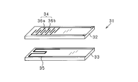
- FIG. 2 is a perspective view showing a main part configuration of a sensor element constituting the particulate matter sensor.
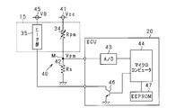
- FIG. 3 is an electrical configuration diagram regarding the particulate matter sensor.
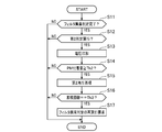
- FIG. 4 is a flowchart showing the procedure of the second reproduction process.
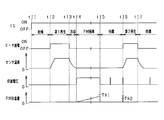
- FIG. 5 is a timing chart showing an aspect of the second reproduction process.
- FIG. 6 is a diagram showing the relationship between the travel distance or travel time and the standby time.
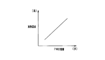
- FIG. 7A is a diagram showing the relationship between the amount of particulate matter adhered and the heating temperature of the heater.
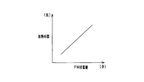
- FIG. 7B is a diagram illustrating the relationship between the amount of particulate matter adhered and the heating time of the heater.
- This embodiment uses a vehicle exhaust treatment system equipped with an engine as an example.
- a particulate matter filter hereinafter referred to as “PM filter” as a filter device is provided in an exhaust pipe of an engine, and a PM sensor is provided downstream thereof.
- the exhaust treatment system monitors the abnormality of the PM filter based on the adhesion amount of PM detected by a particulate matter sensor (hereinafter referred to as “PM sensor”).
- FIG. 1 is a configuration diagram showing a schematic configuration of the present system.
- the engine 11 shown in FIG. 1 is a diesel engine.
- the engine 11 is provided with a fuel injection valve 12 as an actuator related to the operation of the engine 11.
- a PM filter 14 is provided in the exhaust pipe 13 of the engine 11.
- a PM sensor 15 is provided on the downstream side of the PM filter 14.
- the ECU 20 includes a microcomputer including a CPU, ROM, RAM, and the like. ECU20 performs various control of the engine 11 according to a driving
- FIG. 2 is an exploded perspective view showing a main configuration of the sensor element 31 constituting the PM sensor 15.
- FIG. 3 is an electrical configuration diagram regarding the PM sensor 15.
- the sensor element 31 has two long plate-like insulating substrates 32 and 33.
- the insulating substrate 32 is provided with a PM detector 34 for detecting the amount of PM attached.
- the insulating substrate 32 corresponds to the “attachment portion” to which the conductive PM contained in the exhaust is attached.
- the insulating substrate 33 is provided with a heater portion 35 for heating the sensor element 31.
- the sensor element 31 is configured by laminating an insulating substrate 32 and an insulating substrate 33 in two layers.
- a detection electrode 36a and a detection electrode 36b are provided apart from each other on the surface of the substrate opposite to the surface laminated on the insulating substrate 33.
- the PM detection unit 34 includes the pair of detection electrodes 36a and 36b.
- Each of the detection electrodes 36a and 36b has a shape having a plurality of comb teeth (comb shape).
- the detection electrodes 36a and 36b are arranged to face each other with a predetermined interval so that the comb teeth are staggered.
- the detection electrodes 36a and 36b correspond to “a pair of counter electrodes”.
- the heater part 35 is comprised by heat generating bodies, such as a heating wire.
- the shape of the pair of detection electrodes 36a and 36b is not limited to the above shape.
- the detection electrodes 36a and 36b may be provided in a curved shape.
- the detection electrodes 36a and 36b may be configured such that a pair of electrode portions each constituted by a single line are arranged to face each other in parallel at a predetermined distance.
- the PM sensor 15 has a holding part (not shown) for holding the sensor element 31.
- the sensor element 31 is fixed to the exhaust pipe 13 with one end thereof being held by the holding portion.
- the PM sensor 15 is attached to the exhaust pipe 13 as follows.
- the PM sensor 15 is provided such that a portion of the sensor element 31 including at least the PM detection unit 34 and the heater unit 35 is located inside the exhaust pipe 13.
- the PM sensor 15 is provided so that the insulating substrate 32 (a portion to which PM is attached) faces the upstream side of the exhaust flow.
- the PM sensor 15 has a protective cover that covers the protruding portion of the sensor element 31.
- the PM sensor 15 configured as described above detects the amount of adhesion of PM by the following method.
- the resistance value of the PM detection unit 34 (resistance value between the detection electrode 36a and the detection electrode 36b) changes.
- the change in the resistance value corresponds to the amount of PM attached. For this reason, the PM sensor 15 detects the amount of adhesion of PM using the change in the resistance value of the PM detection unit 34.
- a sensor power supply 41 is connected to one end of the PM detector 34 in the PM sensor 15.
- a shunt resistor 42 is connected to the other end side of the PM detection unit 34.
- the sensor power supply 41 is constituted by a constant voltage circuit or the like, and the constant voltage Vcc is 5V.
- a voltage dividing circuit 40 is formed by the PM detection unit 34 and the shunt resistor 42, and the voltage at the intermediate point M is used as the PM detection voltage Vpm (sensor output value). Is input.
- the resistance value Rpm changes according to the amount of adhesion of PM.
- the PM detection voltage Vpm varies depending on the resistance value Rpm of the PM detector 34 and the resistance value Rs of the shunt resistor 42.
- the PM detection voltage Vpm is input to the microcomputer 44 via the A / D converter 43.
- the microcomputer 44 calculates the adhesion amount of PM according to the PM detection voltage Vpm. Further, the microcomputer 44 switches the sensor power supply 41 between the on state and the off state. Thereby, the microcomputer 44 performs switching control between a voltage application state and a non-application state to the pair of detection electrodes 36a and 36b.
- PM is electrostatically induced in the PM detection unit 34 in a state where a voltage is applied to the pair of detection electrodes 36a and 36b, and is collected on the insulating substrate 32 (electrostatic trapping). Collected). Then, the PM detection voltage Vpm corresponding to the amount of PM adhesion is detected.
- a heater power supply 45 is connected to the heater section 35 of the PM sensor 15.
- the heater power supply 45 is an in-vehicle battery or the like.
- the heater unit 35 is heated by power supply from the heater power supply 45.
- a transistor 46 is connected to the low side of the heater unit 35 as a switching element. In the case of such a configuration, the microcomputer 44 controls the heating of the heater unit 35 by turning on / off the transistor 46.
- the temperature of the adhered PM rises and the PM is forcibly burned.
- the PM adhering to the insulating substrate 32 of the sensor element 31 is burned and removed by such forced combustion.
- the microcomputer 44 performs heating control of the heater unit 35 on the assumption that a request for forced combustion of PM is generated, for example, after the engine 11 is started or after the operation is completed.
- the forced combustion process of PM is performed in the PM sensor 15 in order to regenerate the PM adhesion amount detection function. Therefore, the forced combustion process of PM in the PM sensor 15 is also referred to as a sensor regeneration process.
- the ECU 20 is provided with an EEPROM 47 (registered trademark) as a backup memory for storing learning values, abnormality diagnosis values, and the like.
- EEPROM 47 registered trademark
- the ECU20 performs the abnormality determination process of PM filter 14 based on the amount of adhesion of PM. Specifically, the ECU 20 performs a sensor regeneration process (first regeneration process) after the engine 11 is started. The ECU 20 performs control to continuously apply a voltage to the detection electrodes 36a and 36b until a predetermined period (predetermined voltage application period) elapses after the sensor regeneration process ends. Thereby, in the sensor control device, PM that has passed through the PM filter 14 is attached (electrostatically collected) to the insulating substrate 32 of the sensor element 31 in a state where the voltage is continuously applied to the detection electrodes 36a and 36b.
- the ECU 20 determines whether or not the PM adhesion amount on the insulating substrate 32 is equal to or greater than the abnormality determination threshold Th1 when the predetermined period has elapsed (first determination; adhesion amount determination processing).
- first determination the ECU 20 turns on an abnormality warning lamp or the like, assuming that an abnormality such as cracking or melting damage has occurred in the PM filter 14 when it is determined that the PM adhesion amount is equal to or greater than the abnormality determination threshold Th1. Inform the user.
- the operation of the engine 11 is restricted by fail-safe processing.
- the abnormality determination threshold Th1 is set in advance as a value for determining whether or not the amount of PM reaching the sensor element 31 is an appropriate amount.
- the voltage is continuously applied to the detection electrodes 36a and 36b only during a predetermined period (predetermined voltage application period) after the first regeneration process.
- predetermined voltage application period a predetermined voltage application period
- PM is adhered (electrostatic collection) to the insulating substrate 32 of the sensor element 31 in a state where a voltage is continuously applied to the detection electrodes 36a and 36b.
- PM contained in the exhaust adheres to the insulating substrate 32 outside the voltage application period. In such a case, it is considered that the adhesion amount of PM has increased especially after the elapse of a predetermined period.
- the amount of PM attached is greater when PM is attached due to electrostatic collection. Can be considered. In such a state, it is considered that an excessive adhesion state of PM is likely to occur. For this reason, in the sensor control device, even if the first regeneration process is performed after the engine 11 is started, PM remains on the insulating substrate 32, and as a result, the determination accuracy of the adhesion amount of PM may be lowered. .
- the ECU 20 performs the following control in order to prevent the PM adhesion amount from becoming excessive after the abnormality determination process in which the first determination is completed. Specifically, the ECU 20 determines whether or not the PM adhesion amount is equal to or greater than the excess determination threshold Th2 when a predetermined condition is satisfied after the elapse of a predetermined period (predetermined voltage application period) (second determination). ; Excess adhesion determination processing). In the second determination, the ECU 20 performs a sensor regeneration process (second regeneration process) by heating the heater unit 35 when it is determined that the PM adhesion amount is equal to or greater than the excess determination threshold Th2. Note that the excess determination threshold Th2 is set in advance as a value with which PM can be burned and removed by the sensor regeneration process (second regeneration process). At this time, the excess determination threshold Th2 is preferably smaller than the abnormality determination threshold Th1 (Th2 ⁇ Th1).
- step S11 determines whether the abnormality determination process of PM filter 14 is completed and it is determined that PM filter 14 is functioning normally.
- a flag indicating that (normal) is set. Therefore, when the flag is set, the ECU 20 determines that the abnormality determination process of the PM filter 14 has been completed and it is determined that the PM filter 14 is functioning normally (positive determination). .
- the flag is not set, the ECU 20 determines that the abnormality determination process of the PM filter 14 has not been completed or that it has been determined that the PM filter 14 is not functioning normally (negative determination). ).
- step S12 the ECU 20 progresses to the process of step S12, when affirmation determination is carried out in the determination process of step S11 (YES). On the other hand, when a negative determination is made in the determination process of step S11 (NO), the ECU 20 ends the present process.
- the ECU 20 determines whether or not a predetermined condition for determining whether or not the second determination is necessary is satisfied after the abnormality determination process of the PM filter 14 (step S12).
- a predetermined standby time is set as the predetermined condition. Therefore, the ECU 20 determines that a predetermined condition for performing the second determination is satisfied (affirmative determination) every time a predetermined standby time (for example, 5 minutes) elapses after the abnormality determination process of the PM filter 14. On the other hand, the ECU 20 determines that the predetermined condition for performing the second determination is not satisfied if the predetermined standby time has not elapsed after the abnormality determination process of the PM filter 14 (negative determination).
- step S13 the ECU 20 progresses to the process of step S13, when affirmation determination is carried out in the determination process of step S12 (YES). On the other hand, when a negative determination is made in the determination process of step S12 (NO), the ECU 20 ends this process.
- the ECU 20 applies a voltage temporarily (for example, less than 1 second) to the detection electrodes 36a and 36b, and calculates the amount of adhesion of PM (step S13). Subsequently, the ECU 20 determines whether or not the PM adhesion amount is equal to or greater than the excess determination threshold Th2 (step S14). The ECU 20 makes an affirmative determination when the adhesion amount of PM is equal to or greater than the excess determination threshold Th2. On the other hand, the ECU 20 makes a negative determination when the amount of PM attached is less than the excess determination threshold Th2.
- step S14 If the determination in step S14 is affirmative (YES), the ECU 20 increments the number of times that the PM adhesion amount is determined to be greater than or equal to the excess determination threshold Th2, and proceeds to the process in step S15. On the other hand, when a negative determination is made in the determination process of step S14 (NO), the ECU 20 ends the present process. Next, the ECU 20 performs a second regeneration process of the PM sensor 15 by heating the heater unit 35 (step S15). In the second regeneration process, the heater unit 35 is heated based on a predetermined heating temperature and heating time, and PM adhering to the sensor element 31 is removed by combustion.
- the first regeneration process is a process intended to burn and remove all PM adhering to the insulating substrate 32 of the sensor element 31.
- the second regeneration process is a process aimed at suppressing the excessive adhesion state of PM after the first regeneration process.
- the heating temperature and heating time of the heater unit 35 in the second regeneration process may be the same as in the first regeneration process, but the heating time may be set shorter than in the first regeneration process. Further, the heating temperature may be set low.
- the ECU 20 determines whether or not the cumulative number of times that the PM adhesion amount has been determined to be greater than or equal to the excess determination threshold Th2 has reached a predetermined number Th3 (for example, two times) (step). S16). The ECU 20 makes an affirmative determination when the cumulative number reaches the predetermined number Th3. On the other hand, the ECU 20 makes a negative determination when the cumulative number does not reach the predetermined number Th3. If an affirmative determination is made in the determination process of step S16 (YES), the ECU 20 proceeds to the process of step S17. On the other hand, when a negative determination is made in the determination process of step S16 (NO), the ECU 20 ends the present process. The ECU 20 performs the first regeneration process for the PM sensor 15 and requests re-execution of the abnormality determination process for the PM filter 14 (step S17).
- a predetermined number Th3 for example, two times
- the engine 11 is started as the IG switch is turned on.
- the temperature inside the exhaust pipe 13 rises and the condensed water inside the exhaust pipe 13 evaporates.
- energization of the heater unit 35 is started and the first regeneration process is performed.
- the temperature of the PM sensor 15 rises, and the PM adhering to the insulating substrate 32 of the sensor element 31 is burned and removed.
- energization of the heater unit 35 is stopped, and the first regeneration process is completed. Thereby, the temperature of PM sensor 15 falls.
- a voltage is continuously applied to the detection electrodes 36a and 36b until a predetermined period (predetermined voltage application period) elapses. Then, the PM that has passed through the PM filter 14 is attached to the insulating substrate 32 (electrostatic collection) while a voltage is applied to the detection electrodes 36a and 36b. At this time, the adhesion amount of PM increases.
- a first determination is made to determine whether or not the PM adhesion amount on the insulating substrate 32 is equal to or greater than the abnormality determination threshold Th1. As a result, when it is determined that the PM adhesion amount is less than the abnormality determination threshold Th1, the abnormality determination process of the PM filter 14 is completed.
- a voltage is temporarily applied to the detection electrodes 36a and 36b, and the amount of adhesion of PM is obtained.
- the passage of the standby time means that a predetermined condition for determining whether or not the second determination is necessary is satisfied. Therefore, after time t15, every time a predetermined standby time elapses, a second determination is made to determine whether or not the PM adhesion amount is equal to or greater than the excess determination threshold Th2. As a result, when it is determined that the PM adhesion amount is equal to or greater than the excess determination threshold Th2, energization of the heater unit 35 is started, and the second regeneration process is performed.
- the sensor control device determines whether or not the PM adhesion amount is greater than or equal to the excess determination threshold Th2 when a predetermined condition is satisfied outside the voltage application period (abnormality determination period of the PM filter 14) of the detection electrodes 36a and 36b. Determine whether.
- the sensor control device performs the second regeneration process of the PM sensor 15 by the heating of the heater unit 35 when it is determined that the PM adhesion amount is equal to or greater than the excess determination threshold Th2. Therefore, in the sensor control apparatus according to the present embodiment, even if PM adheres to the insulating substrate 32 outside the voltage application period, the excessive adhesion state of PM is not left as it is. Thereby, in the sensor control apparatus, it can suppress that PM remains excessively after the 1st reproduction
- the sensor control apparatus determines whether or not the PM adhesion amount is greater than or equal to the excess determination threshold Th2 every time a predetermined standby time elapses after the abnormality determination process of the PM filter 14 (second determination is performed). carry out).
- the sensor control device performs the second regeneration process when it is determined that the PM adhesion amount is equal to or greater than the excess determination threshold Th2 after the voltage application period of the detection electrodes 36a and 36b has elapsed. For this reason, in the sensor control apparatus of this embodiment, the PM excessive adhesion state is not left as it is after a predetermined voltage application period in which the PM excessive adhesion state is likely to occur.
- the sensor control device temporarily applies a voltage to the detection electrodes 36a and 36b every time a predetermined standby time elapses after the abnormality determination process of the PM filter 14, thereby determining the amount of adhesion of PM. judge.
- the sensor control device since the voltage application to the detection electrodes 36a and 36b is temporary, the sensor control device according to the present embodiment can determine the adhesion amount of PM while suppressing the power consumption accompanying the voltage application. Moreover, in a sensor control apparatus, it can suppress that PM is electrostatically collected, and can suppress the increase in the adhesion amount of PM.
- the sensor control device determines whether or not the cumulative number of times that the PM adhesion amount has been determined to be equal to or greater than the excess determination threshold Th2 has reached a predetermined number Th3 after the abnormality determination process of the PM filter 14. As a result, when it is determined that the cumulative number has reached the predetermined number Th3, the sensor control device performs the first regeneration process of the PM sensor 15 and the abnormality determination process of the PM filter 14. At this time, in a situation where the second regeneration process of the PM sensor 15 is repeatedly performed, it is determined that it is necessary to check whether the PM filter 14 is functioning normally, and abnormality determination is performed. For this reason, in the sensor control apparatus of this embodiment, the presence or absence of abnormality of PM filter 14 can be grasped
- the excess determination threshold Th2 is preferably set to a value smaller than the abnormality determination threshold Th1. .
- the excess determination threshold Th2 is set to a value smaller than the abnormality determination threshold Th1.
- the sensor control device may be configured to perform the second determination for determining the excessive adhesion state of PM after the engine 11 is started and before the first first regeneration process is executed. As a result, when it is determined that the PM adhesion amount is equal to or greater than the excess determination threshold Th2, the second regeneration state for eliminating the PM excessive adhesion state is started after the first first regeneration process after the engine 11 is started. It is good to execute the reproduction process.
- the sensor control device acquires the travel distance or travel time (vehicle information) of the vehicle, and uses predetermined conditions for determining whether the second determination is necessary based on the acquired vehicle information. It may be configured to set a certain waiting time. In this case, as shown in FIG. 6, the longer the travel distance or travel time of the vehicle, the shorter the standby time until the second determination is performed.
- the second determination for determining whether or not to execute the second regeneration process of the PM sensor 15 is performed.
- the frequency of doing is increased.
- the sensor control device may be configured to set the standby time based on the travel distance and travel time of the vehicle.
- the information acquisition unit that acquires vehicle information including at least one of the travel distance and travel time of the vehicle, and the predetermined condition for performing the second determination are changed based on the vehicle information.
- the heating temperature and heating time of the heater unit 35 used during the second regeneration process of the PM sensor 15 are set to the PM adhesion amount. It is good also as a structure set based on. In this case, as shown in FIG. 7A and FIG. 7B, the heating temperature is preferably set higher or the heating time is set longer as the PM adhesion amount is larger. Thereby, in the sensor control apparatus, the second regeneration process can be appropriately performed in consideration of the adhesion amount of PM.
- the sensor control device includes a processing condition changing unit that changes the processing condition of the second regeneration process based on the attached amount when the attached amount of the particulate matter is determined to be equal to or greater than the predetermined value. It may be.
- a standby time is set in advance as a predetermined condition for determining whether or not the second determination is necessary, and the second determination is performed every time the predetermined standby time elapses after the abnormality determination process.
- the sensor control device may be configured such that a travel distance is determined in advance as a predetermined condition for performing the second determination, and the second determination is performed every time the predetermined travel distance is reached after the abnormality determination process.
- the heating time of the heater unit 35 used in the second regeneration process is set shorter than that in the first regeneration process, but this is not a limitation.
- the heating time of the heater unit 35 during the second regeneration process may be set longer than that in the first regeneration process.
- the sensor control device may be configured to set the heating temperature of the heater unit 35 higher during the second regeneration process than in the first regeneration process.
- the resistance value of the PM detection unit 34 (resistance value between the detection electrode 36a and the detection electrode 36b) changes.
- the PM adhesion amount is detected using such a change in the resistance value of the PM detection unit 34, but this is not restrictive.
- the sensor control device may be configured to detect the adhesion amount of PM using a change in capacitance.
- SYMBOLS 11 Engine (internal combustion engine), 13 ... Exhaust pipe (exhaust passage), 15 ... PM sensor (sensor), 20 ... ECU (sensor control device), 32 ... Insulating substrate (attachment part), 35 ... Heater part (heater) ), 36a, 36b... Detection electrodes (a pair of counter electrodes).
Landscapes
- Engineering & Computer Science (AREA)
- Chemical & Material Sciences (AREA)
- Combustion & Propulsion (AREA)
- Mechanical Engineering (AREA)
- General Engineering & Computer Science (AREA)
- Life Sciences & Earth Sciences (AREA)
- Physics & Mathematics (AREA)
- Health & Medical Sciences (AREA)
- Dispersion Chemistry (AREA)
- Analytical Chemistry (AREA)
- Biochemistry (AREA)
- General Health & Medical Sciences (AREA)
- General Physics & Mathematics (AREA)
- Immunology (AREA)
- Pathology (AREA)
- Processes For Solid Components From Exhaust (AREA)
- Investigating Or Analyzing Materials By The Use Of Electric Means (AREA)
- Chemical Kinetics & Catalysis (AREA)
Abstract
Selon la présente invention, une unité de commande électronique (20) effectue un premier processus de régénération pour un capteur de matière particulaire (PM) (15) par chauffage à l'aide d'une unité de chauffage (35) après qu'un moteur (11) a démarré, et applique de façon intermittente une tension à des électrodes de détection (36a, 36b) dans une période d'application de tension prescrite après le premier processus de régénération. L'unité de commande électronique (20) amène la matière particulaire à adhérer à un substrat d'isolation (32) tandis qu'une tension est appliquée, et détermine la quantité de matière particulaire adhérant au substrat d'isolation (32) au point dans le temps auquel la période d'application de tension s'est écoulée. Quand une condition prescrite est satisfaite dans une période autre que la période d'application de tension, l'unité de commande électronique (20) détermine si la quantité de matière particulaire adhérant au substrat d'isolation (32) est supérieure ou égale à une valeur de seuil de détermination d'excès. Quand il est déterminé que la quantité de matière particulaire adhérant est supérieure ou égale à la valeur de seuil de détermination d'excès, l'unité de commande électronique (20) effectue un second processus de régénération pour le capteur de matière particulaire (15) par chauffage à l'aide de l'unité de chauffage (35).
Priority Applications (3)
| Application Number | Priority Date | Filing Date | Title |
|---|---|---|---|
| CN201780006661.7A CN108474280B (zh) | 2016-01-19 | 2017-01-18 | 传感器控制装置 |
| DE112017000421.7T DE112017000421T5 (de) | 2016-01-19 | 2017-01-18 | Sensorsteuerungsvorrichtung |
| US16/070,894 US10871117B2 (en) | 2016-01-19 | 2017-01-18 | Sensor control apparatus |
Applications Claiming Priority (2)
| Application Number | Priority Date | Filing Date | Title |
|---|---|---|---|
| JP2016007835A JP6439706B2 (ja) | 2016-01-19 | 2016-01-19 | センサ制御装置 |
| JP2016-007835 | 2016-01-19 |
Publications (1)
| Publication Number | Publication Date |
|---|---|
| WO2017126516A1 true WO2017126516A1 (fr) | 2017-07-27 |
Family
ID=59362255
Family Applications (1)
| Application Number | Title | Priority Date | Filing Date |
|---|---|---|---|
| PCT/JP2017/001452 WO2017126516A1 (fr) | 2016-01-19 | 2017-01-18 | Dispositif de commande de capteur |
Country Status (5)
| Country | Link |
|---|---|
| US (1) | US10871117B2 (fr) |
| JP (1) | JP6439706B2 (fr) |
| CN (1) | CN108474280B (fr) |
| DE (1) | DE112017000421T5 (fr) |
| WO (1) | WO2017126516A1 (fr) |
Families Citing this family (1)
| Publication number | Priority date | Publication date | Assignee | Title |
|---|---|---|---|---|
| JP7087530B2 (ja) * | 2018-03-23 | 2022-06-21 | コベルコ建機株式会社 | 排ガス異常検出装置 |
Citations (3)
| Publication number | Priority date | Publication date | Assignee | Title |
|---|---|---|---|---|
| WO2010103834A1 (fr) * | 2009-03-11 | 2010-09-16 | 本田技研工業株式会社 | Dispositif de détection de panne pour filtre de purification de gaz d'échappement |
| JP2012127268A (ja) * | 2010-12-15 | 2012-07-05 | Toyota Motor Corp | 内燃機関の制御装置 |
| JP2012149525A (ja) * | 2011-01-17 | 2012-08-09 | Mazda Motor Corp | エンジンの排気浄化装置 |
Family Cites Families (5)
| Publication number | Priority date | Publication date | Assignee | Title |
|---|---|---|---|---|
| JPS5115873B2 (fr) | 1972-01-14 | 1976-05-20 | ||
| CN101008630A (zh) * | 2006-01-23 | 2007-08-01 | 株式会社电装 | 用于气体传感器的气体检测元件及制造该元件的方法 |
| JP5115873B2 (ja) | 2010-12-08 | 2013-01-09 | 株式会社デンソー | パティキュレートフィルタの故障検出装置 |
| CN102791996B (zh) | 2011-03-15 | 2015-07-29 | 丰田自动车株式会社 | 内燃机的控制装置 |
| AU2011374432B2 (en) | 2011-08-04 | 2015-11-12 | Toyota Jidosha Kabushiki Kaisha | Device for controlling internal combustion engine |
-
2016
- 2016-01-19 JP JP2016007835A patent/JP6439706B2/ja active Active
-
2017
- 2017-01-18 US US16/070,894 patent/US10871117B2/en active Active
- 2017-01-18 WO PCT/JP2017/001452 patent/WO2017126516A1/fr active Application Filing
- 2017-01-18 CN CN201780006661.7A patent/CN108474280B/zh not_active Expired - Fee Related
- 2017-01-18 DE DE112017000421.7T patent/DE112017000421T5/de not_active Withdrawn
Patent Citations (3)
| Publication number | Priority date | Publication date | Assignee | Title |
|---|---|---|---|---|
| WO2010103834A1 (fr) * | 2009-03-11 | 2010-09-16 | 本田技研工業株式会社 | Dispositif de détection de panne pour filtre de purification de gaz d'échappement |
| JP2012127268A (ja) * | 2010-12-15 | 2012-07-05 | Toyota Motor Corp | 内燃機関の制御装置 |
| JP2012149525A (ja) * | 2011-01-17 | 2012-08-09 | Mazda Motor Corp | エンジンの排気浄化装置 |
Also Published As
| Publication number | Publication date |
|---|---|
| CN108474280B (zh) | 2020-05-12 |
| CN108474280A (zh) | 2018-08-31 |
| JP2017129038A (ja) | 2017-07-27 |
| DE112017000421T5 (de) | 2018-10-11 |
| JP6439706B2 (ja) | 2018-12-19 |
| US20190032588A1 (en) | 2019-01-31 |
| US10871117B2 (en) | 2020-12-22 |
Similar Documents
| Publication | Publication Date | Title |
|---|---|---|
| JP5408069B2 (ja) | センサ制御装置及びこれを備える排気処理システム | |
| JP5348089B2 (ja) | センサ制御装置 | |
| US9534524B1 (en) | Dual rate diesel particulate filter leak monitor | |
| JP5331578B2 (ja) | 粒子状物質検出手段の故障判定装置 | |
| JP5278615B2 (ja) | 内燃機関の粒子状物質検出装置 | |
| US20120031169A1 (en) | Sensor controller | |
| WO2012124054A1 (fr) | Dispositif de commande de moteur à combustion interne | |
| JP5240408B1 (ja) | 内燃機関の制御装置 | |
| JP2012037371A (ja) | センサ制御装置 | |
| JP6361918B2 (ja) | フィルタの故障検出装置 | |
| JP6481966B2 (ja) | 制御装置 | |
| JP5533477B2 (ja) | エンジン制御装置 | |
| WO2017126516A1 (fr) | Dispositif de commande de capteur | |
| JP5488451B2 (ja) | 微粒子検出装置 | |
| JP2012037369A (ja) | センサ制御装置 | |
| JP2012077668A (ja) | センサ制御装置 | |
| JP4889717B2 (ja) | 粒子状物質検出装置 | |
| JP6256421B2 (ja) | フィルタ異常判定装置 | |
| WO2017002828A1 (fr) | Dispositif de commande de tension appliquée à un réacteur à plasma et dispositif de commande de réacteur à plasma | |
| JP5614295B2 (ja) | エンジンの排気浄化装置 | |
| JP2011089791A (ja) | 粒子状物質検出装置 | |
| JP5908414B2 (ja) | 粒子状物質検出装置 | |
| JP2018071363A (ja) | センサ制御システム及びセンサの制御方法 | |
| JP2017129038A5 (fr) | ||
| JP6707287B2 (ja) | リアクタ温度推定装置 |
Legal Events
| Date | Code | Title | Description |
|---|---|---|---|
| 121 | Ep: the epo has been informed by wipo that ep was designated in this application |
Ref document number: 17741393 Country of ref document: EP Kind code of ref document: A1 |
|
| WWE | Wipo information: entry into national phase |
Ref document number: 112017000421 Country of ref document: DE |
|
| 122 | Ep: pct application non-entry in european phase |
Ref document number: 17741393 Country of ref document: EP Kind code of ref document: A1 |