WO2017126516A1 - Sensor control device - Google Patents
Sensor control device Download PDFInfo
- Publication number
- WO2017126516A1 WO2017126516A1 PCT/JP2017/001452 JP2017001452W WO2017126516A1 WO 2017126516 A1 WO2017126516 A1 WO 2017126516A1 JP 2017001452 W JP2017001452 W JP 2017001452W WO 2017126516 A1 WO2017126516 A1 WO 2017126516A1
- Authority
- WO
- WIPO (PCT)
- Prior art keywords
- sensor
- particulate matter
- amount
- determination
- sensor control
- Prior art date
Links
Images


Classifications
-
- F—MECHANICAL ENGINEERING; LIGHTING; HEATING; WEAPONS; BLASTING
- F01—MACHINES OR ENGINES IN GENERAL; ENGINE PLANTS IN GENERAL; STEAM ENGINES
- F01N—GAS-FLOW SILENCERS OR EXHAUST APPARATUS FOR MACHINES OR ENGINES IN GENERAL; GAS-FLOW SILENCERS OR EXHAUST APPARATUS FOR INTERNAL COMBUSTION ENGINES
- F01N3/00—Exhaust or silencing apparatus having means for purifying, rendering innocuous, or otherwise treating exhaust
- F01N3/02—Exhaust or silencing apparatus having means for purifying, rendering innocuous, or otherwise treating exhaust for cooling, or for removing solid constituents of, exhaust
-
- F—MECHANICAL ENGINEERING; LIGHTING; HEATING; WEAPONS; BLASTING
- F02—COMBUSTION ENGINES; HOT-GAS OR COMBUSTION-PRODUCT ENGINE PLANTS
- F02D—CONTROLLING COMBUSTION ENGINES
- F02D41/00—Electrical control of supply of combustible mixture or its constituents
- F02D41/02—Circuit arrangements for generating control signals
- F02D41/14—Introducing closed-loop corrections
- F02D41/1438—Introducing closed-loop corrections using means for determining characteristics of the combustion gases; Sensors therefor
- F02D41/1444—Introducing closed-loop corrections using means for determining characteristics of the combustion gases; Sensors therefor characterised by the characteristics of the combustion gases
- F02D41/1466—Introducing closed-loop corrections using means for determining characteristics of the combustion gases; Sensors therefor characterised by the characteristics of the combustion gases the characteristics being a soot concentration or content
-
- F—MECHANICAL ENGINEERING; LIGHTING; HEATING; WEAPONS; BLASTING
- F02—COMBUSTION ENGINES; HOT-GAS OR COMBUSTION-PRODUCT ENGINE PLANTS
- F02D—CONTROLLING COMBUSTION ENGINES
- F02D41/00—Electrical control of supply of combustible mixture or its constituents
- F02D41/02—Circuit arrangements for generating control signals
- F02D41/14—Introducing closed-loop corrections
- F02D41/1438—Introducing closed-loop corrections using means for determining characteristics of the combustion gases; Sensors therefor
- F02D41/1493—Details
- F02D41/1494—Control of sensor heater
-
- G—PHYSICS
- G01—MEASURING; TESTING
- G01N—INVESTIGATING OR ANALYSING MATERIALS BY DETERMINING THEIR CHEMICAL OR PHYSICAL PROPERTIES
- G01N15/00—Investigating characteristics of particles; Investigating permeability, pore-volume, or surface-area of porous materials
- G01N15/06—Investigating concentration of particle suspensions
- G01N15/0656—Investigating concentration of particle suspensions using electric, e.g. electrostatic methods or magnetic methods
-
- F—MECHANICAL ENGINEERING; LIGHTING; HEATING; WEAPONS; BLASTING
- F01—MACHINES OR ENGINES IN GENERAL; ENGINE PLANTS IN GENERAL; STEAM ENGINES
- F01N—GAS-FLOW SILENCERS OR EXHAUST APPARATUS FOR MACHINES OR ENGINES IN GENERAL; GAS-FLOW SILENCERS OR EXHAUST APPARATUS FOR INTERNAL COMBUSTION ENGINES
- F01N11/00—Monitoring or diagnostic devices for exhaust-gas treatment apparatus, e.g. for catalytic activity
-
- F—MECHANICAL ENGINEERING; LIGHTING; HEATING; WEAPONS; BLASTING
- F01—MACHINES OR ENGINES IN GENERAL; ENGINE PLANTS IN GENERAL; STEAM ENGINES
- F01N—GAS-FLOW SILENCERS OR EXHAUST APPARATUS FOR MACHINES OR ENGINES IN GENERAL; GAS-FLOW SILENCERS OR EXHAUST APPARATUS FOR INTERNAL COMBUSTION ENGINES
- F01N2240/00—Combination or association of two or more different exhaust treating devices, or of at least one such device with an auxiliary device, not covered by indexing codes F01N2230/00 or F01N2250/00, one of the devices being
- F01N2240/16—Combination or association of two or more different exhaust treating devices, or of at least one such device with an auxiliary device, not covered by indexing codes F01N2230/00 or F01N2250/00, one of the devices being an electric heater, i.e. a resistance heater
-
- F—MECHANICAL ENGINEERING; LIGHTING; HEATING; WEAPONS; BLASTING
- F01—MACHINES OR ENGINES IN GENERAL; ENGINE PLANTS IN GENERAL; STEAM ENGINES
- F01N—GAS-FLOW SILENCERS OR EXHAUST APPARATUS FOR MACHINES OR ENGINES IN GENERAL; GAS-FLOW SILENCERS OR EXHAUST APPARATUS FOR INTERNAL COMBUSTION ENGINES
- F01N2560/00—Exhaust systems with means for detecting or measuring exhaust gas components or characteristics
- F01N2560/05—Exhaust systems with means for detecting or measuring exhaust gas components or characteristics the means being a particulate sensor
-
- F—MECHANICAL ENGINEERING; LIGHTING; HEATING; WEAPONS; BLASTING
- F01—MACHINES OR ENGINES IN GENERAL; ENGINE PLANTS IN GENERAL; STEAM ENGINES
- F01N—GAS-FLOW SILENCERS OR EXHAUST APPARATUS FOR MACHINES OR ENGINES IN GENERAL; GAS-FLOW SILENCERS OR EXHAUST APPARATUS FOR INTERNAL COMBUSTION ENGINES
- F01N2560/00—Exhaust systems with means for detecting or measuring exhaust gas components or characteristics
- F01N2560/20—Sensor having heating means
-
- F—MECHANICAL ENGINEERING; LIGHTING; HEATING; WEAPONS; BLASTING
- F01—MACHINES OR ENGINES IN GENERAL; ENGINE PLANTS IN GENERAL; STEAM ENGINES
- F01N—GAS-FLOW SILENCERS OR EXHAUST APPARATUS FOR MACHINES OR ENGINES IN GENERAL; GAS-FLOW SILENCERS OR EXHAUST APPARATUS FOR INTERNAL COMBUSTION ENGINES
- F01N2900/00—Details of electrical control or of the monitoring of the exhaust gas treating apparatus
- F01N2900/04—Methods of control or diagnosing
- F01N2900/0422—Methods of control or diagnosing measuring the elapsed time
-
- Y—GENERAL TAGGING OF NEW TECHNOLOGICAL DEVELOPMENTS; GENERAL TAGGING OF CROSS-SECTIONAL TECHNOLOGIES SPANNING OVER SEVERAL SECTIONS OF THE IPC; TECHNICAL SUBJECTS COVERED BY FORMER USPC CROSS-REFERENCE ART COLLECTIONS [XRACs] AND DIGESTS
- Y02—TECHNOLOGIES OR APPLICATIONS FOR MITIGATION OR ADAPTATION AGAINST CLIMATE CHANGE
- Y02T—CLIMATE CHANGE MITIGATION TECHNOLOGIES RELATED TO TRANSPORTATION
- Y02T10/00—Road transport of goods or passengers
- Y02T10/10—Internal combustion engine [ICE] based vehicles
- Y02T10/12—Improving ICE efficiencies
Definitions
- the present disclosure relates to a sensor control technique for detecting particulate matter (PM) in an exhaust passage of an internal combustion engine.
- a filter device for collecting particulate matter is provided in the exhaust passage from the engine.
- a particulate matter detection sensor is provided on the downstream side of the filter device to determine whether there is an abnormality such as cracking or melting of the filter device.
- Patent Document 1 discloses the following technique in order to accurately grasp the amount of particulate matter reaching the sensor. Specifically, a first regeneration process for burning and removing particulate matter remaining on the particulate matter sensor is performed. Thereafter, by continuously applying a voltage to the counter electrode, the particulate matter is likely to adhere to the adherend. Then, when the predetermined period has elapsed, the amount of particulate matter attached is determined.
- the present disclosure provides a sensor control technology that can suppress the particulate matter from remaining excessively after the first regeneration process and can appropriately determine the amount of particulate matter adhered.
- the sensor control device includes a portion to be attached (32) to which a conductive particulate matter contained in exhaust gas is attached, and a pair of counter electrodes (36a and 36b) provided to be separated from the portion to be attached. And a heater (35) that heats the adherend, and is applied to a sensor (15) that outputs a detection signal corresponding to the amount of particulate matter adhered, and the sensor is an exhaust passage of the internal combustion engine (11).
- the particulate matter is adhered to the adherend in a state where a voltage is continuously applied to the counter electrode, and when the predetermined period has elapsed.
- Particles in the adherend A first determination unit that determines the amount of substance adhered, and a second determination unit that determines whether or not the amount of particulate matter adhered to the adherend is greater than or equal to a predetermined value when a predetermined condition is satisfied outside a predetermined period. And a second regeneration unit that performs a second regeneration process of the sensor by heating the heater when the amount of adhesion is determined to be greater than or equal to a predetermined value by the second determination unit.
- the particulate matter is attached to the adherend in a state where the voltage is continuously applied to the counter electrode for a predetermined period after the first regeneration process.
- the portion to be adhered becomes an excessively adhered state of the particulate matter.
- the sensor control device determines whether or not the adhesion amount of the particulate matter is equal to or greater than a predetermined value when a predetermined condition is satisfied outside the predetermined period.
- the sensor control device performs the second regeneration process of the sensor by heating the heater when the adhesion amount of the particulate matter is determined to be a predetermined value or more. For this reason, in the sensor control device of the present disclosure, even when the particulate matter adheres to the adherend, except for the period of voltage application to the counter electrode, the excessively attached state of the particulate matter is not left as it is. Thereby, in the sensor control device of the present disclosure, it is possible to suppress the particulate matter from remaining excessively after the first regeneration process, and to appropriately determine the adhesion amount of the particulate matter.
- FIG. 1 is a configuration diagram showing an outline of an exhaust treatment system.
- FIG. 2 is a perspective view showing a main part configuration of a sensor element constituting the particulate matter sensor.
- FIG. 3 is an electrical configuration diagram regarding the particulate matter sensor.
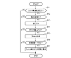
- FIG. 4 is a flowchart showing the procedure of the second reproduction process.
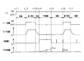
- FIG. 5 is a timing chart showing an aspect of the second reproduction process.
- FIG. 6 is a diagram showing the relationship between the travel distance or travel time and the standby time.
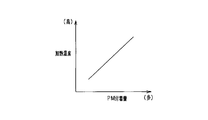
- FIG. 7A is a diagram showing the relationship between the amount of particulate matter adhered and the heating temperature of the heater.
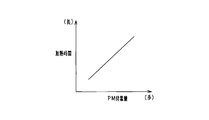
- FIG. 7B is a diagram illustrating the relationship between the amount of particulate matter adhered and the heating time of the heater.
- This embodiment uses a vehicle exhaust treatment system equipped with an engine as an example.
- a particulate matter filter hereinafter referred to as “PM filter” as a filter device is provided in an exhaust pipe of an engine, and a PM sensor is provided downstream thereof.
- the exhaust treatment system monitors the abnormality of the PM filter based on the adhesion amount of PM detected by a particulate matter sensor (hereinafter referred to as “PM sensor”).
- FIG. 1 is a configuration diagram showing a schematic configuration of the present system.
- the engine 11 shown in FIG. 1 is a diesel engine.
- the engine 11 is provided with a fuel injection valve 12 as an actuator related to the operation of the engine 11.
- a PM filter 14 is provided in the exhaust pipe 13 of the engine 11.
- a PM sensor 15 is provided on the downstream side of the PM filter 14.
- the ECU 20 includes a microcomputer including a CPU, ROM, RAM, and the like. ECU20 performs various control of the engine 11 according to a driving
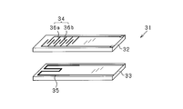
- FIG. 2 is an exploded perspective view showing a main configuration of the sensor element 31 constituting the PM sensor 15.
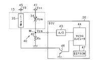
- FIG. 3 is an electrical configuration diagram regarding the PM sensor 15.
- the sensor element 31 has two long plate-like insulating substrates 32 and 33.
- the insulating substrate 32 is provided with a PM detector 34 for detecting the amount of PM attached.
- the insulating substrate 32 corresponds to the “attachment portion” to which the conductive PM contained in the exhaust is attached.
- the insulating substrate 33 is provided with a heater portion 35 for heating the sensor element 31.
- the sensor element 31 is configured by laminating an insulating substrate 32 and an insulating substrate 33 in two layers.
- a detection electrode 36a and a detection electrode 36b are provided apart from each other on the surface of the substrate opposite to the surface laminated on the insulating substrate 33.
- the PM detection unit 34 includes the pair of detection electrodes 36a and 36b.
- Each of the detection electrodes 36a and 36b has a shape having a plurality of comb teeth (comb shape).
- the detection electrodes 36a and 36b are arranged to face each other with a predetermined interval so that the comb teeth are staggered.
- the detection electrodes 36a and 36b correspond to “a pair of counter electrodes”.
- the heater part 35 is comprised by heat generating bodies, such as a heating wire.
- the shape of the pair of detection electrodes 36a and 36b is not limited to the above shape.
- the detection electrodes 36a and 36b may be provided in a curved shape.
- the detection electrodes 36a and 36b may be configured such that a pair of electrode portions each constituted by a single line are arranged to face each other in parallel at a predetermined distance.
- the PM sensor 15 has a holding part (not shown) for holding the sensor element 31.
- the sensor element 31 is fixed to the exhaust pipe 13 with one end thereof being held by the holding portion.
- the PM sensor 15 is attached to the exhaust pipe 13 as follows.
- the PM sensor 15 is provided such that a portion of the sensor element 31 including at least the PM detection unit 34 and the heater unit 35 is located inside the exhaust pipe 13.
- the PM sensor 15 is provided so that the insulating substrate 32 (a portion to which PM is attached) faces the upstream side of the exhaust flow.
- the PM sensor 15 has a protective cover that covers the protruding portion of the sensor element 31.
- the PM sensor 15 configured as described above detects the amount of adhesion of PM by the following method.
- the resistance value of the PM detection unit 34 (resistance value between the detection electrode 36a and the detection electrode 36b) changes.
- the change in the resistance value corresponds to the amount of PM attached. For this reason, the PM sensor 15 detects the amount of adhesion of PM using the change in the resistance value of the PM detection unit 34.
- a sensor power supply 41 is connected to one end of the PM detector 34 in the PM sensor 15.
- a shunt resistor 42 is connected to the other end side of the PM detection unit 34.
- the sensor power supply 41 is constituted by a constant voltage circuit or the like, and the constant voltage Vcc is 5V.
- a voltage dividing circuit 40 is formed by the PM detection unit 34 and the shunt resistor 42, and the voltage at the intermediate point M is used as the PM detection voltage Vpm (sensor output value). Is input.
- the resistance value Rpm changes according to the amount of adhesion of PM.
- the PM detection voltage Vpm varies depending on the resistance value Rpm of the PM detector 34 and the resistance value Rs of the shunt resistor 42.
- the PM detection voltage Vpm is input to the microcomputer 44 via the A / D converter 43.
- the microcomputer 44 calculates the adhesion amount of PM according to the PM detection voltage Vpm. Further, the microcomputer 44 switches the sensor power supply 41 between the on state and the off state. Thereby, the microcomputer 44 performs switching control between a voltage application state and a non-application state to the pair of detection electrodes 36a and 36b.
- PM is electrostatically induced in the PM detection unit 34 in a state where a voltage is applied to the pair of detection electrodes 36a and 36b, and is collected on the insulating substrate 32 (electrostatic trapping). Collected). Then, the PM detection voltage Vpm corresponding to the amount of PM adhesion is detected.
- a heater power supply 45 is connected to the heater section 35 of the PM sensor 15.
- the heater power supply 45 is an in-vehicle battery or the like.
- the heater unit 35 is heated by power supply from the heater power supply 45.
- a transistor 46 is connected to the low side of the heater unit 35 as a switching element. In the case of such a configuration, the microcomputer 44 controls the heating of the heater unit 35 by turning on / off the transistor 46.
- the temperature of the adhered PM rises and the PM is forcibly burned.
- the PM adhering to the insulating substrate 32 of the sensor element 31 is burned and removed by such forced combustion.
- the microcomputer 44 performs heating control of the heater unit 35 on the assumption that a request for forced combustion of PM is generated, for example, after the engine 11 is started or after the operation is completed.
- the forced combustion process of PM is performed in the PM sensor 15 in order to regenerate the PM adhesion amount detection function. Therefore, the forced combustion process of PM in the PM sensor 15 is also referred to as a sensor regeneration process.
- the ECU 20 is provided with an EEPROM 47 (registered trademark) as a backup memory for storing learning values, abnormality diagnosis values, and the like.
- EEPROM 47 registered trademark
- the ECU20 performs the abnormality determination process of PM filter 14 based on the amount of adhesion of PM. Specifically, the ECU 20 performs a sensor regeneration process (first regeneration process) after the engine 11 is started. The ECU 20 performs control to continuously apply a voltage to the detection electrodes 36a and 36b until a predetermined period (predetermined voltage application period) elapses after the sensor regeneration process ends. Thereby, in the sensor control device, PM that has passed through the PM filter 14 is attached (electrostatically collected) to the insulating substrate 32 of the sensor element 31 in a state where the voltage is continuously applied to the detection electrodes 36a and 36b.
- the ECU 20 determines whether or not the PM adhesion amount on the insulating substrate 32 is equal to or greater than the abnormality determination threshold Th1 when the predetermined period has elapsed (first determination; adhesion amount determination processing).
- first determination the ECU 20 turns on an abnormality warning lamp or the like, assuming that an abnormality such as cracking or melting damage has occurred in the PM filter 14 when it is determined that the PM adhesion amount is equal to or greater than the abnormality determination threshold Th1. Inform the user.
- the operation of the engine 11 is restricted by fail-safe processing.
- the abnormality determination threshold Th1 is set in advance as a value for determining whether or not the amount of PM reaching the sensor element 31 is an appropriate amount.
- the voltage is continuously applied to the detection electrodes 36a and 36b only during a predetermined period (predetermined voltage application period) after the first regeneration process.
- predetermined voltage application period a predetermined voltage application period
- PM is adhered (electrostatic collection) to the insulating substrate 32 of the sensor element 31 in a state where a voltage is continuously applied to the detection electrodes 36a and 36b.
- PM contained in the exhaust adheres to the insulating substrate 32 outside the voltage application period. In such a case, it is considered that the adhesion amount of PM has increased especially after the elapse of a predetermined period.
- the amount of PM attached is greater when PM is attached due to electrostatic collection. Can be considered. In such a state, it is considered that an excessive adhesion state of PM is likely to occur. For this reason, in the sensor control device, even if the first regeneration process is performed after the engine 11 is started, PM remains on the insulating substrate 32, and as a result, the determination accuracy of the adhesion amount of PM may be lowered. .
- the ECU 20 performs the following control in order to prevent the PM adhesion amount from becoming excessive after the abnormality determination process in which the first determination is completed. Specifically, the ECU 20 determines whether or not the PM adhesion amount is equal to or greater than the excess determination threshold Th2 when a predetermined condition is satisfied after the elapse of a predetermined period (predetermined voltage application period) (second determination). ; Excess adhesion determination processing). In the second determination, the ECU 20 performs a sensor regeneration process (second regeneration process) by heating the heater unit 35 when it is determined that the PM adhesion amount is equal to or greater than the excess determination threshold Th2. Note that the excess determination threshold Th2 is set in advance as a value with which PM can be burned and removed by the sensor regeneration process (second regeneration process). At this time, the excess determination threshold Th2 is preferably smaller than the abnormality determination threshold Th1 (Th2 ⁇ Th1).
- step S11 determines whether the abnormality determination process of PM filter 14 is completed and it is determined that PM filter 14 is functioning normally.
- a flag indicating that (normal) is set. Therefore, when the flag is set, the ECU 20 determines that the abnormality determination process of the PM filter 14 has been completed and it is determined that the PM filter 14 is functioning normally (positive determination). .
- the flag is not set, the ECU 20 determines that the abnormality determination process of the PM filter 14 has not been completed or that it has been determined that the PM filter 14 is not functioning normally (negative determination). ).
- step S12 the ECU 20 progresses to the process of step S12, when affirmation determination is carried out in the determination process of step S11 (YES). On the other hand, when a negative determination is made in the determination process of step S11 (NO), the ECU 20 ends the present process.
- the ECU 20 determines whether or not a predetermined condition for determining whether or not the second determination is necessary is satisfied after the abnormality determination process of the PM filter 14 (step S12).
- a predetermined standby time is set as the predetermined condition. Therefore, the ECU 20 determines that a predetermined condition for performing the second determination is satisfied (affirmative determination) every time a predetermined standby time (for example, 5 minutes) elapses after the abnormality determination process of the PM filter 14. On the other hand, the ECU 20 determines that the predetermined condition for performing the second determination is not satisfied if the predetermined standby time has not elapsed after the abnormality determination process of the PM filter 14 (negative determination).
- step S13 the ECU 20 progresses to the process of step S13, when affirmation determination is carried out in the determination process of step S12 (YES). On the other hand, when a negative determination is made in the determination process of step S12 (NO), the ECU 20 ends this process.
- the ECU 20 applies a voltage temporarily (for example, less than 1 second) to the detection electrodes 36a and 36b, and calculates the amount of adhesion of PM (step S13). Subsequently, the ECU 20 determines whether or not the PM adhesion amount is equal to or greater than the excess determination threshold Th2 (step S14). The ECU 20 makes an affirmative determination when the adhesion amount of PM is equal to or greater than the excess determination threshold Th2. On the other hand, the ECU 20 makes a negative determination when the amount of PM attached is less than the excess determination threshold Th2.
- step S14 If the determination in step S14 is affirmative (YES), the ECU 20 increments the number of times that the PM adhesion amount is determined to be greater than or equal to the excess determination threshold Th2, and proceeds to the process in step S15. On the other hand, when a negative determination is made in the determination process of step S14 (NO), the ECU 20 ends the present process. Next, the ECU 20 performs a second regeneration process of the PM sensor 15 by heating the heater unit 35 (step S15). In the second regeneration process, the heater unit 35 is heated based on a predetermined heating temperature and heating time, and PM adhering to the sensor element 31 is removed by combustion.
- the first regeneration process is a process intended to burn and remove all PM adhering to the insulating substrate 32 of the sensor element 31.
- the second regeneration process is a process aimed at suppressing the excessive adhesion state of PM after the first regeneration process.
- the heating temperature and heating time of the heater unit 35 in the second regeneration process may be the same as in the first regeneration process, but the heating time may be set shorter than in the first regeneration process. Further, the heating temperature may be set low.
- the ECU 20 determines whether or not the cumulative number of times that the PM adhesion amount has been determined to be greater than or equal to the excess determination threshold Th2 has reached a predetermined number Th3 (for example, two times) (step). S16). The ECU 20 makes an affirmative determination when the cumulative number reaches the predetermined number Th3. On the other hand, the ECU 20 makes a negative determination when the cumulative number does not reach the predetermined number Th3. If an affirmative determination is made in the determination process of step S16 (YES), the ECU 20 proceeds to the process of step S17. On the other hand, when a negative determination is made in the determination process of step S16 (NO), the ECU 20 ends the present process. The ECU 20 performs the first regeneration process for the PM sensor 15 and requests re-execution of the abnormality determination process for the PM filter 14 (step S17).
- a predetermined number Th3 for example, two times
- the engine 11 is started as the IG switch is turned on.
- the temperature inside the exhaust pipe 13 rises and the condensed water inside the exhaust pipe 13 evaporates.
- energization of the heater unit 35 is started and the first regeneration process is performed.
- the temperature of the PM sensor 15 rises, and the PM adhering to the insulating substrate 32 of the sensor element 31 is burned and removed.
- energization of the heater unit 35 is stopped, and the first regeneration process is completed. Thereby, the temperature of PM sensor 15 falls.
- a voltage is continuously applied to the detection electrodes 36a and 36b until a predetermined period (predetermined voltage application period) elapses. Then, the PM that has passed through the PM filter 14 is attached to the insulating substrate 32 (electrostatic collection) while a voltage is applied to the detection electrodes 36a and 36b. At this time, the adhesion amount of PM increases.
- a first determination is made to determine whether or not the PM adhesion amount on the insulating substrate 32 is equal to or greater than the abnormality determination threshold Th1. As a result, when it is determined that the PM adhesion amount is less than the abnormality determination threshold Th1, the abnormality determination process of the PM filter 14 is completed.
- a voltage is temporarily applied to the detection electrodes 36a and 36b, and the amount of adhesion of PM is obtained.
- the passage of the standby time means that a predetermined condition for determining whether or not the second determination is necessary is satisfied. Therefore, after time t15, every time a predetermined standby time elapses, a second determination is made to determine whether or not the PM adhesion amount is equal to or greater than the excess determination threshold Th2. As a result, when it is determined that the PM adhesion amount is equal to or greater than the excess determination threshold Th2, energization of the heater unit 35 is started, and the second regeneration process is performed.
- the sensor control device determines whether or not the PM adhesion amount is greater than or equal to the excess determination threshold Th2 when a predetermined condition is satisfied outside the voltage application period (abnormality determination period of the PM filter 14) of the detection electrodes 36a and 36b. Determine whether.
- the sensor control device performs the second regeneration process of the PM sensor 15 by the heating of the heater unit 35 when it is determined that the PM adhesion amount is equal to or greater than the excess determination threshold Th2. Therefore, in the sensor control apparatus according to the present embodiment, even if PM adheres to the insulating substrate 32 outside the voltage application period, the excessive adhesion state of PM is not left as it is. Thereby, in the sensor control apparatus, it can suppress that PM remains excessively after the 1st reproduction
- the sensor control apparatus determines whether or not the PM adhesion amount is greater than or equal to the excess determination threshold Th2 every time a predetermined standby time elapses after the abnormality determination process of the PM filter 14 (second determination is performed). carry out).
- the sensor control device performs the second regeneration process when it is determined that the PM adhesion amount is equal to or greater than the excess determination threshold Th2 after the voltage application period of the detection electrodes 36a and 36b has elapsed. For this reason, in the sensor control apparatus of this embodiment, the PM excessive adhesion state is not left as it is after a predetermined voltage application period in which the PM excessive adhesion state is likely to occur.
- the sensor control device temporarily applies a voltage to the detection electrodes 36a and 36b every time a predetermined standby time elapses after the abnormality determination process of the PM filter 14, thereby determining the amount of adhesion of PM. judge.
- the sensor control device since the voltage application to the detection electrodes 36a and 36b is temporary, the sensor control device according to the present embodiment can determine the adhesion amount of PM while suppressing the power consumption accompanying the voltage application. Moreover, in a sensor control apparatus, it can suppress that PM is electrostatically collected, and can suppress the increase in the adhesion amount of PM.
- the sensor control device determines whether or not the cumulative number of times that the PM adhesion amount has been determined to be equal to or greater than the excess determination threshold Th2 has reached a predetermined number Th3 after the abnormality determination process of the PM filter 14. As a result, when it is determined that the cumulative number has reached the predetermined number Th3, the sensor control device performs the first regeneration process of the PM sensor 15 and the abnormality determination process of the PM filter 14. At this time, in a situation where the second regeneration process of the PM sensor 15 is repeatedly performed, it is determined that it is necessary to check whether the PM filter 14 is functioning normally, and abnormality determination is performed. For this reason, in the sensor control apparatus of this embodiment, the presence or absence of abnormality of PM filter 14 can be grasped
- the excess determination threshold Th2 is preferably set to a value smaller than the abnormality determination threshold Th1. .
- the excess determination threshold Th2 is set to a value smaller than the abnormality determination threshold Th1.
- the sensor control device may be configured to perform the second determination for determining the excessive adhesion state of PM after the engine 11 is started and before the first first regeneration process is executed. As a result, when it is determined that the PM adhesion amount is equal to or greater than the excess determination threshold Th2, the second regeneration state for eliminating the PM excessive adhesion state is started after the first first regeneration process after the engine 11 is started. It is good to execute the reproduction process.
- the sensor control device acquires the travel distance or travel time (vehicle information) of the vehicle, and uses predetermined conditions for determining whether the second determination is necessary based on the acquired vehicle information. It may be configured to set a certain waiting time. In this case, as shown in FIG. 6, the longer the travel distance or travel time of the vehicle, the shorter the standby time until the second determination is performed.
- the second determination for determining whether or not to execute the second regeneration process of the PM sensor 15 is performed.
- the frequency of doing is increased.
- the sensor control device may be configured to set the standby time based on the travel distance and travel time of the vehicle.
- the information acquisition unit that acquires vehicle information including at least one of the travel distance and travel time of the vehicle, and the predetermined condition for performing the second determination are changed based on the vehicle information.
- the heating temperature and heating time of the heater unit 35 used during the second regeneration process of the PM sensor 15 are set to the PM adhesion amount. It is good also as a structure set based on. In this case, as shown in FIG. 7A and FIG. 7B, the heating temperature is preferably set higher or the heating time is set longer as the PM adhesion amount is larger. Thereby, in the sensor control apparatus, the second regeneration process can be appropriately performed in consideration of the adhesion amount of PM.
- the sensor control device includes a processing condition changing unit that changes the processing condition of the second regeneration process based on the attached amount when the attached amount of the particulate matter is determined to be equal to or greater than the predetermined value. It may be.
- a standby time is set in advance as a predetermined condition for determining whether or not the second determination is necessary, and the second determination is performed every time the predetermined standby time elapses after the abnormality determination process.
- the sensor control device may be configured such that a travel distance is determined in advance as a predetermined condition for performing the second determination, and the second determination is performed every time the predetermined travel distance is reached after the abnormality determination process.
- the heating time of the heater unit 35 used in the second regeneration process is set shorter than that in the first regeneration process, but this is not a limitation.
- the heating time of the heater unit 35 during the second regeneration process may be set longer than that in the first regeneration process.
- the sensor control device may be configured to set the heating temperature of the heater unit 35 higher during the second regeneration process than in the first regeneration process.
- the resistance value of the PM detection unit 34 (resistance value between the detection electrode 36a and the detection electrode 36b) changes.
- the PM adhesion amount is detected using such a change in the resistance value of the PM detection unit 34, but this is not restrictive.
- the sensor control device may be configured to detect the adhesion amount of PM using a change in capacitance.
- SYMBOLS 11 Engine (internal combustion engine), 13 ... Exhaust pipe (exhaust passage), 15 ... PM sensor (sensor), 20 ... ECU (sensor control device), 32 ... Insulating substrate (attachment part), 35 ... Heater part (heater) ), 36a, 36b... Detection electrodes (a pair of counter electrodes).
Abstract
In the present invention an ECU 20 implements a first regeneration process for a particulate matter (PM) sensor 15 by heating by means of a heater unit 35 after an engine 11 has started, and intermittently applies voltage to detection electrodes 36a and 36b in a prescribed voltage application period after the first regeneration process. The ECU 20 causes PM to adhere to an insulation substrate 32 while voltage is being applied, and determines the amount of PM adhered to the insulation substrate 32 at the point in time at which the voltage application period has elapsed. When a prescribed condition is satisfied in a period other than the voltage application period the ECU 20 determines whether the amount of PM adhered to the insulation substrate 32 is equal to or greater than an excess-determination threshold value. When it is determined that the amount of adhered PM is equal to or greater than the excess-determination threshold value the ECU 20 implements a second regeneration process for the PM sensor 15 by heating by means of the heater unit 35.
Description
本開示は、内燃機関の排気通路において粒子状物質(PM:Particulate Matter)を検出するセンサの制御技術に関する。
The present disclosure relates to a sensor control technique for detecting particulate matter (PM) in an exhaust passage of an internal combustion engine.
従来では、エンジンから排出される粒子状物質が大気に放出されることを抑制するために、次のような技術が知られている。エンジンからの排気通路には、粒子状物質を捕集するフィルタ装置が設けられている。そして、フィルタ装置の下流側には、粒子状物質検出センサ(PMセンサ)を設け、フィルタ装置の割れや溶損等の異常有無を判定する。
Conventionally, the following techniques are known in order to suppress release of particulate matter discharged from the engine to the atmosphere. A filter device for collecting particulate matter is provided in the exhaust passage from the engine. A particulate matter detection sensor (PM sensor) is provided on the downstream side of the filter device to determine whether there is an abnormality such as cracking or melting of the filter device.
特許文献1には、センサに到達する粒子状物質の量を正確に把握するために、次のような技術が開示されている。具体的には、粒子状物質センサ上に残留している粒子状物質を燃焼除去する第1再生処理を行う。その後、対向電極に対して継続的に電圧を印加することによって、被付着部に粒子状物質が付着しやすい状態となる。そして、所定期間が経過した時点において、粒子状物質の付着量を判定する。
Patent Document 1 discloses the following technique in order to accurately grasp the amount of particulate matter reaching the sensor. Specifically, a first regeneration process for burning and removing particulate matter remaining on the particulate matter sensor is performed. Thereafter, by continuously applying a voltage to the counter electrode, the particulate matter is likely to adhere to the adherend. Then, when the predetermined period has elapsed, the amount of particulate matter attached is determined.
所定期間に限定して対向電極への電圧の印加を行う構成では、所定期間以外において、排気中に含まれる粒子状物質が被付着部に付着することが考えられる。このような状態を放置すると、被付着部は、粒子状物質の過剰付着状態となることが懸念される。よって、エンジン始動後に、粒子状物質を燃焼除去する第1再生処理が行われたとしても、被付着部には、粒子状物質が残留し、その結果、粒子状物質の付着量の判定精度が低下するおそれがある。
In the configuration in which the voltage is applied to the counter electrode only for a predetermined period, it is conceivable that the particulate matter contained in the exhaust adheres to the adherend other than the predetermined period. If such a state is left as it is, there is a concern that the adherend will be in an excessively adhered state of particulate matter. Therefore, even if the first regeneration process for burning and removing the particulate matter is performed after the engine is started, the particulate matter remains in the adherend, and as a result, the determination accuracy of the attached amount of the particulate matter is improved. May decrease.
本開示は、第1再生処理後に粒子状物質が過剰に残留することを抑制し、粒子状物質の付着量を適正に判定できるセンサ制御技術を提供する。
The present disclosure provides a sensor control technology that can suppress the particulate matter from remaining excessively after the first regeneration process and can appropriately determine the amount of particulate matter adhered.
以下、本開示の技術の一態様であるセンサ制御装置について説明する。
Hereinafter, a sensor control device which is an aspect of the technology of the present disclosure will be described.
本開示のセンサ制御装置は、排気中に含まれる導電性の粒子状物質を付着させる被付着部(32)と、被付着部に互いに離間して設けられる一対の対向電極(36a,36b)と、被付着部を加熱するヒータ(35)と、を有し、粒子状物質の付着量に応じた検出信号を出力するセンサ(15)に適用され、該センサは内燃機関(11)の排気通路(13)に設けられており、検出信号に基づき粒子状物質の付着量を検出するセンサ制御装置(20)であって、内燃機関の始動後において、ヒータの加熱によりセンサの第1再生処理を実施する第1再生部と、第1再生処理の実施後の所定期間において、対向電極に継続的に電圧を印加した状態で被付着部に粒子状物質を付着させ、所定期間が経過した時点において、被付着部における粒子状物質の付着量を判定する第1判定部と、所定期間以外において、所定条件が成立した場合に、被付着部における粒子状物質の付着量が所定値以上か否かを判定する第2判定部と、第2判定部により付着量が所定値以上と判定された場合に、ヒータの加熱によりセンサの第2再生処理を実施する第2再生部と、を備える。
The sensor control device according to the present disclosure includes a portion to be attached (32) to which a conductive particulate matter contained in exhaust gas is attached, and a pair of counter electrodes (36a and 36b) provided to be separated from the portion to be attached. And a heater (35) that heats the adherend, and is applied to a sensor (15) that outputs a detection signal corresponding to the amount of particulate matter adhered, and the sensor is an exhaust passage of the internal combustion engine (11). A sensor control device (20) provided in (13) for detecting the amount of particulate matter adhering based on a detection signal, wherein after the internal combustion engine is started, the heater is heated to perform a first regeneration process of the sensor. In a predetermined period after the first regeneration unit to be implemented and the first regeneration process, the particulate matter is adhered to the adherend in a state where a voltage is continuously applied to the counter electrode, and when the predetermined period has elapsed. , Particles in the adherend A first determination unit that determines the amount of substance adhered, and a second determination unit that determines whether or not the amount of particulate matter adhered to the adherend is greater than or equal to a predetermined value when a predetermined condition is satisfied outside a predetermined period. And a second regeneration unit that performs a second regeneration process of the sensor by heating the heater when the amount of adhesion is determined to be greater than or equal to a predetermined value by the second determination unit.
センサ制御装置では、第1再生処理後の所定期間に限定して、対向電極に継続的に電圧を印加した状態で被付着部に粒子状物質を付着させる。このようなセンサ制御装置では、所定期間以外において、排気中に含まれる粒子状物質が被付着部に付着することを確認している。そのため、センサ制御装置では、このような状態を放置すると、被付着部が粒子状物質の過剰付着状態となる。このように、センサ制御装置では、内燃機関の始動後に第1再生処理が行われたとしても、被付着部に粒子状物質が残留し、粒子状物質の付着量の判定精度が低下するおそれがある。
In the sensor control device, the particulate matter is attached to the adherend in a state where the voltage is continuously applied to the counter electrode for a predetermined period after the first regeneration process. In such a sensor control device, it is confirmed that the particulate matter contained in the exhaust gas adheres to the adherend other than the predetermined period. Therefore, in the sensor control device, if such a state is left as it is, the portion to be adhered becomes an excessively adhered state of the particulate matter. As described above, in the sensor control device, even if the first regeneration process is performed after the internal combustion engine is started, the particulate matter may remain in the adherend, and the determination accuracy of the attached amount of the particulate matter may be reduced. is there.
これに対して、本開示のセンサ制御装置は、所定期間以外において、所定条件が成立した場合に、粒子状物質の付着量が所定値以上か否かを判定する。その結果、本開示のセンサ制御装置は、粒子状物質の付着量が所定値以上と判定された場合に、ヒータの加熱によりセンサの第2再生処理を行う。そのため、本開示のセンサ制御装置では、対向電極への電圧の印加の期間以外において、被付着部に粒子状物質が付着しても、粒子状物質の過剰付着状態がそのまま放置されない。これにより、本開示のセンサ制御装置では、第1再生処理後に粒子状物質が過剰に残留することを抑制し、粒子状物質の付着量を適正に判定できる。
On the other hand, the sensor control device according to the present disclosure determines whether or not the adhesion amount of the particulate matter is equal to or greater than a predetermined value when a predetermined condition is satisfied outside the predetermined period. As a result, the sensor control device according to the present disclosure performs the second regeneration process of the sensor by heating the heater when the adhesion amount of the particulate matter is determined to be a predetermined value or more. For this reason, in the sensor control device of the present disclosure, even when the particulate matter adheres to the adherend, except for the period of voltage application to the counter electrode, the excessively attached state of the particulate matter is not left as it is. Thereby, in the sensor control device of the present disclosure, it is possible to suppress the particulate matter from remaining excessively after the first regeneration process, and to appropriately determine the adhesion amount of the particulate matter.
本実施形態は、エンジンを備える車両の排気処理システムを例にする。排気処理システムは、エンジンの排気管に、フィルタ装置としての粒子状物質フィルタ(以下「PMフィルタ」という)が設けられており、その下流側にPMセンサが設けられている。排気処理システムは、粒子状物質センサ(以下「PMセンサ」という)により検出されるPMの付着量に基づいて、PMフィルタの異常を監視する。
This embodiment uses a vehicle exhaust treatment system equipped with an engine as an example. In the exhaust treatment system, a particulate matter filter (hereinafter referred to as “PM filter”) as a filter device is provided in an exhaust pipe of an engine, and a PM sensor is provided downstream thereof. The exhaust treatment system monitors the abnormality of the PM filter based on the adhesion amount of PM detected by a particulate matter sensor (hereinafter referred to as “PM sensor”).
図1は、本システムの概略構成を示す構成図である。図1に示すエンジン11は、ディーゼルエンジンである。エンジン11には、エンジン11の運転に関わるアクチュエータとして、燃料噴射弁12が設けられている。エンジン11の排気管13には、PMフィルタ14が設けられている。PMフィルタ14の下流側には、PMセンサ15が設けられている。
FIG. 1 is a configuration diagram showing a schematic configuration of the present system. The engine 11 shown in FIG. 1 is a diesel engine. The engine 11 is provided with a fuel injection valve 12 as an actuator related to the operation of the engine 11. A PM filter 14 is provided in the exhaust pipe 13 of the engine 11. A PM sensor 15 is provided on the downstream side of the PM filter 14.
ECU20は、CPU、ROM、RAM等を含むマイクロコンピュータを備える。ECU20は、ROMに記憶された制御プログラムを実行することによって、運転状態に応じたエンジン11の各種制御を行う。具体的には、ECU20は、上記センサ等から検出信号が入力され、入力された検出信号に基づいて、燃料の噴射量や噴射時期を演算し、燃料噴射弁12の駆動を制御する。本実施形態では、ECU20が「センサ制御装置」に相当する。
The ECU 20 includes a microcomputer including a CPU, ROM, RAM, and the like. ECU20 performs various control of the engine 11 according to a driving | running state by running the control program memorize | stored in ROM. Specifically, the ECU 20 receives a detection signal from the sensor or the like, calculates the fuel injection amount and injection timing based on the input detection signal, and controls the drive of the fuel injection valve 12. In the present embodiment, the ECU 20 corresponds to a “sensor control device”.
次に、PMセンサ15の構成、及びPMセンサ15に関する電気的構成について、図2及び図3を用いて説明する。図2は、PMセンサ15を構成するセンサ素子31の要部構成を示す分解斜視図である。図3は、PMセンサ15に関する電気的構成図である。
Next, the configuration of the PM sensor 15 and the electrical configuration related to the PM sensor 15 will be described with reference to FIGS. FIG. 2 is an exploded perspective view showing a main configuration of the sensor element 31 constituting the PM sensor 15. FIG. 3 is an electrical configuration diagram regarding the PM sensor 15.
図2に示すように、センサ素子31は、長尺板状の2枚の絶縁基板32,33を有している。絶縁基板32には、PMの付着量を検出するためのPM検出部34が設けられている。本実施形態では、絶縁基板32が排気中に含まれる導電性のPMを付着させる「被付着部」に相当する。また、絶縁基板33には、センサ素子31を加熱するためのヒータ部35が設けられている。センサ素子31は、絶縁基板32と絶縁基板33とが二層に積層されることにより構成されている。
As shown in FIG. 2, the sensor element 31 has two long plate-like insulating substrates 32 and 33. The insulating substrate 32 is provided with a PM detector 34 for detecting the amount of PM attached. In the present embodiment, the insulating substrate 32 corresponds to the “attachment portion” to which the conductive PM contained in the exhaust is attached. The insulating substrate 33 is provided with a heater portion 35 for heating the sensor element 31. The sensor element 31 is configured by laminating an insulating substrate 32 and an insulating substrate 33 in two layers.
絶縁基板32には、絶縁基板33に積層される面とは反対側の基板表面に、検出電極36aと検出電極36bとが互いに離間して設けられている。PM検出部34は、この一対の検出電極36a,36bにより構成されている。検出電極36a,36bは、各々複数の櫛歯を有する形状(櫛歯形状)をしている。検出電極36a,36bは、櫛歯同士が互い違いとなるように、所定間隔をあけて対向配置されている。本実施形態では、検出電極36a,36bが「一対の対向電極」に相当する。また、ヒータ部35は、電熱線等の発熱体により構成されている。
In the insulating substrate 32, a detection electrode 36a and a detection electrode 36b are provided apart from each other on the surface of the substrate opposite to the surface laminated on the insulating substrate 33. The PM detection unit 34 includes the pair of detection electrodes 36a and 36b. Each of the detection electrodes 36a and 36b has a shape having a plurality of comb teeth (comb shape). The detection electrodes 36a and 36b are arranged to face each other with a predetermined interval so that the comb teeth are staggered. In the present embodiment, the detection electrodes 36a and 36b correspond to “a pair of counter electrodes”. Moreover, the heater part 35 is comprised by heat generating bodies, such as a heating wire.
一対の検出電極36a,36bの形状は、上記形状に限定されない。検出電極36a,36bは、曲線形状で設けられてもよい。また、検出電極36a,36bは、各々1本の線により構成される一対の電極部が、所定の距離離れて平行に対向配置されていてもよい。
The shape of the pair of detection electrodes 36a and 36b is not limited to the above shape. The detection electrodes 36a and 36b may be provided in a curved shape. In addition, the detection electrodes 36a and 36b may be configured such that a pair of electrode portions each constituted by a single line are arranged to face each other in parallel at a predetermined distance.
PMセンサ15は、センサ素子31を保持するための保持部(非図示)を有している。センサ素子31は、その一端側が保持部により保持された状態で排気管13に固定される。具体的には、PMセンサ15は、排気管13に対して次のように取り付けられる。PMセンサ15は、センサ素子31のうち、少なくともPM検出部34及びヒータ部35を含む部位が、排気管13の内部に位置するように設けられている。また、PMセンサ15は、絶縁基板32(PMの被付着部)が、排気の流れの上流側を向くように設けられている。これにより、PMを含む排気が排気管13の内部を流れる際、PMセンサ15には、絶縁基板32の検出電極36a,36b及びその周辺にPMが付着する。また、PMセンサ15は、センサ素子31の突出部分を覆う保護カバーを有している。
The PM sensor 15 has a holding part (not shown) for holding the sensor element 31. The sensor element 31 is fixed to the exhaust pipe 13 with one end thereof being held by the holding portion. Specifically, the PM sensor 15 is attached to the exhaust pipe 13 as follows. The PM sensor 15 is provided such that a portion of the sensor element 31 including at least the PM detection unit 34 and the heater unit 35 is located inside the exhaust pipe 13. Further, the PM sensor 15 is provided so that the insulating substrate 32 (a portion to which PM is attached) faces the upstream side of the exhaust flow. As a result, when exhaust gas containing PM flows through the exhaust pipe 13, PM adheres to the detection electrodes 36a and 36b of the insulating substrate 32 and the periphery thereof. The PM sensor 15 has a protective cover that covers the protruding portion of the sensor element 31.
上記構成のPMセンサ15は、次のような方法によりPMの付着量を検出する。排気中のPMがセンサ素子31の絶縁基板32に付着した場合には、PM検出部34の抵抗値(検出電極36aと検出電極36bとの間の抵抗値)が変化する。また、その抵抗値の変化は、PMの付着量に対応している。このようなことから、PMセンサ15は、PM検出部34の抵抗値の変化を利用して、PMの付着量を検出する。
The PM sensor 15 configured as described above detects the amount of adhesion of PM by the following method. When PM in the exhaust gas adheres to the insulating substrate 32 of the sensor element 31, the resistance value of the PM detection unit 34 (resistance value between the detection electrode 36a and the detection electrode 36b) changes. The change in the resistance value corresponds to the amount of PM attached. For this reason, the PM sensor 15 detects the amount of adhesion of PM using the change in the resistance value of the PM detection unit 34.
図3に示すように、PMセンサ15におけるPM検出部34の一端側には、センサ電源41が接続されている。一方、PM検出部34の他端側には、シャント抵抗42が接続されている。センサ電源41は、定電圧回路等により構成されており、定電圧Vccが5Vとなっている。このような構成の場合には、PM検出部34とシャント抵抗42とにより分圧回路40が形成され、それらの中間点Mの電圧が、PMの検出電圧Vpm(センサの出力値)として、ECU20に入力される。具体的には、PM検出部34では、PMの付着量に応じて、抵抗値Rpmが変化する。PMの検出電圧Vpmは、PM検出部34の抵抗値Rpmとシャント抵抗42の抵抗値Rsとにより変化する。そして、PMの検出電圧Vpmは、A/D変換器43を介してマイクロコンピュータ44に入力される。マイクロコンピュータ44は、PMの検出電圧Vpmに応じて、PMの付着量を算出する。また、マイクロコンピュータ44は、センサ電源41のオン状態とオフ状態とを切り替える。これにより、マイクロコンピュータ44は、一対の検出電極36a,36bに対する電圧の印加状態と非印加状態とを切り替え制御する。このような構成の場合には、一対の検出電極36a,36bに対して電圧を印加した状態において、PM検出部34にPMが静電的に誘導され、絶縁基板32に捕集(静電捕集)される。そして、PMの付着量に応じたPMの検出電圧Vpmが検出される。
As shown in FIG. 3, a sensor power supply 41 is connected to one end of the PM detector 34 in the PM sensor 15. On the other hand, a shunt resistor 42 is connected to the other end side of the PM detection unit 34. The sensor power supply 41 is constituted by a constant voltage circuit or the like, and the constant voltage Vcc is 5V. In the case of such a configuration, a voltage dividing circuit 40 is formed by the PM detection unit 34 and the shunt resistor 42, and the voltage at the intermediate point M is used as the PM detection voltage Vpm (sensor output value). Is input. Specifically, in the PM detection unit 34, the resistance value Rpm changes according to the amount of adhesion of PM. The PM detection voltage Vpm varies depending on the resistance value Rpm of the PM detector 34 and the resistance value Rs of the shunt resistor 42. The PM detection voltage Vpm is input to the microcomputer 44 via the A / D converter 43. The microcomputer 44 calculates the adhesion amount of PM according to the PM detection voltage Vpm. Further, the microcomputer 44 switches the sensor power supply 41 between the on state and the off state. Thereby, the microcomputer 44 performs switching control between a voltage application state and a non-application state to the pair of detection electrodes 36a and 36b. In the case of such a configuration, PM is electrostatically induced in the PM detection unit 34 in a state where a voltage is applied to the pair of detection electrodes 36a and 36b, and is collected on the insulating substrate 32 (electrostatic trapping). Collected). Then, the PM detection voltage Vpm corresponding to the amount of PM adhesion is detected.
PMセンサ15のヒータ部35には、ヒータ電源45が接続されている。ヒータ電源45は、車載バッテリ等である。ヒータ部35は、ヒータ電源45からの給電により加熱される。ヒータ部35のローサイドには、スイッチング素子としてトランジスタ46が接続されている。このような構成の場合には、マイクロコンピュータ44がトランジスタ46をオン/オフすることによって、ヒータ部35の加熱制御が行われる。
A heater power supply 45 is connected to the heater section 35 of the PM sensor 15. The heater power supply 45 is an in-vehicle battery or the like. The heater unit 35 is heated by power supply from the heater power supply 45. A transistor 46 is connected to the low side of the heater unit 35 as a switching element. In the case of such a configuration, the microcomputer 44 controls the heating of the heater unit 35 by turning on / off the transistor 46.
センサ素子31の絶縁基板32上にPMが付着した状態でヒータ部35の通電を開始した場合には、付着したPMの温度が上昇し、PMが強制的に燃焼される。センサ制御装置では、こうした強制燃焼によって、センサ素子31の絶縁基板32に付着したPMを燃焼除去する。マイクロコンピュータ44は、例えばエンジン11の始動後や運転終了後に、PMの強制燃焼要求が発生したとして、ヒータ部35の加熱制御を行う。なお、PMの強制燃焼処理は、PMセンサ15において、PMの付着量の検出機能を再生するために行われる。よって、PMセンサ15におけるPMの強制燃焼処理は、センサ再生処理とも称される。
When energization of the heater unit 35 is started in a state where PM adheres to the insulating substrate 32 of the sensor element 31, the temperature of the adhered PM rises and the PM is forcibly burned. In the sensor control device, the PM adhering to the insulating substrate 32 of the sensor element 31 is burned and removed by such forced combustion. The microcomputer 44 performs heating control of the heater unit 35 on the assumption that a request for forced combustion of PM is generated, for example, after the engine 11 is started or after the operation is completed. The forced combustion process of PM is performed in the PM sensor 15 in order to regenerate the PM adhesion amount detection function. Therefore, the forced combustion process of PM in the PM sensor 15 is also referred to as a sensor regeneration process.
その他、ECU20には、学習値や異常診断値等を記憶するためのバックアップ用メモリとして、EEPROM47(登録商標)が設けられている。
In addition, the ECU 20 is provided with an EEPROM 47 (registered trademark) as a backup memory for storing learning values, abnormality diagnosis values, and the like.
ECU20は、PMの付着量に基づいて、PMフィルタ14の異常判定処理を行う。具体的には、ECU20は、エンジン11の始動後にセンサ再生処理(第1再生処理)を行う。ECU20は、センサ再生処理が終了してから所定期間(所定の電圧印加期間)が経過するまで、検出電極36a,36bに対して継続的に電圧を印加する制御を行う。これにより、センサ制御装置では、検出電極36a,36bに継続的に電圧を印加した状態で、PMフィルタ14を通過したPMを、センサ素子31の絶縁基板32に付着(静電捕集)させる。そして、ECU20は、所定期間が経過した時点で、絶縁基板32におけるPMの付着量が異常判定閾値Th1以上か否かを判定する(第1判定;付着量判定処理)。ECU20は、第1判定において、PMの付着量が異常判定閾値Th1以上と判定された場合に、PMフィルタ14に割れや溶損等の異常が発生しているとして、異常警告灯等を点灯させてユーザに知らせる。場合によっては、フェールセーフ処理により、エンジン11の運転制限等を行う。なお、異常判定閾値Th1は、センサ素子31に到達するPMの量が適正量か否かを判定する値として、予め設定されている。
ECU20 performs the abnormality determination process of PM filter 14 based on the amount of adhesion of PM. Specifically, the ECU 20 performs a sensor regeneration process (first regeneration process) after the engine 11 is started. The ECU 20 performs control to continuously apply a voltage to the detection electrodes 36a and 36b until a predetermined period (predetermined voltage application period) elapses after the sensor regeneration process ends. Thereby, in the sensor control device, PM that has passed through the PM filter 14 is attached (electrostatically collected) to the insulating substrate 32 of the sensor element 31 in a state where the voltage is continuously applied to the detection electrodes 36a and 36b. Then, the ECU 20 determines whether or not the PM adhesion amount on the insulating substrate 32 is equal to or greater than the abnormality determination threshold Th1 when the predetermined period has elapsed (first determination; adhesion amount determination processing). In the first determination, the ECU 20 turns on an abnormality warning lamp or the like, assuming that an abnormality such as cracking or melting damage has occurred in the PM filter 14 when it is determined that the PM adhesion amount is equal to or greater than the abnormality determination threshold Th1. Inform the user. In some cases, the operation of the engine 11 is restricted by fail-safe processing. The abnormality determination threshold Th1 is set in advance as a value for determining whether or not the amount of PM reaching the sensor element 31 is an appropriate amount.
センサ制御装置では、第1判定を行うために、第1再生処理後の所定期間(所定の電圧印加期間)に限定して、検出電極36a,36bに継続的に電圧を印加する。そして、センサ制御装置では、検出電極36a,36bに継続的に電圧を印加した状態で、センサ素子31の絶縁基板32にPMを付着(静電捕集)させたとする。しかし、センサ制御装置では、電圧印加期間以外において、排気中に含まれるPMが絶縁基板32に付着することが確認されている。このような場合には、特に所定期間の経過後において、PMの付着量が増加していることが考えられる。すなわち、静電捕集が行われずにPMが付着した場合に比べて、静電捕集が行われたことによりPMが付着した場合の方が、PMの付着量は多い状態になっていることが考えられる。このような状態では、PMの過剰付着状態が発生しやすいと考えられる。このため、センサ制御装置では、エンジン11の始動後に第1再生処理が行われたとしても、絶縁基板32にはPMが残留し、その結果、PMの付着量の判定精度が低下するおそれがある。
In the sensor control device, in order to perform the first determination, the voltage is continuously applied to the detection electrodes 36a and 36b only during a predetermined period (predetermined voltage application period) after the first regeneration process. In the sensor control device, it is assumed that PM is adhered (electrostatic collection) to the insulating substrate 32 of the sensor element 31 in a state where a voltage is continuously applied to the detection electrodes 36a and 36b. However, in the sensor control device, it is confirmed that PM contained in the exhaust adheres to the insulating substrate 32 outside the voltage application period. In such a case, it is considered that the adhesion amount of PM has increased especially after the elapse of a predetermined period. That is, compared to the case where PM adheres without electrostatic collection, the amount of PM attached is greater when PM is attached due to electrostatic collection. Can be considered. In such a state, it is considered that an excessive adhesion state of PM is likely to occur. For this reason, in the sensor control device, even if the first regeneration process is performed after the engine 11 is started, PM remains on the insulating substrate 32, and as a result, the determination accuracy of the adhesion amount of PM may be lowered. .
そこで、本実施形態のセンサ制御装置では、第1判定が終了した異常判定処理後において、PMの付着量が過剰になることを抑制するために、ECU20が次のような制御を行う。具体的には、ECU20は、所定期間(所定の電圧印加期間)の経過後において、所定条件が成立した場合に、PMの付着量が過剰判定閾値Th2以上か否かを判定する(第2判定;過剰付着判定処理)。ECU20は、第2判定において、PMの付着量が過剰判定閾値Th2以上と判定された場合に、ヒータ部35の加熱によって、センサ再生処理(第2再生処理)を行う。なお、過剰判定閾値Th2は、センサ再生処理(第2再生処理)によって、PMが燃焼除去できる値として、予め設定されている。このとき過剰判定閾値Th2は、異常判定閾値Th1より小さい値が好ましい(Th2<Th1)。
Therefore, in the sensor control device of the present embodiment, the ECU 20 performs the following control in order to prevent the PM adhesion amount from becoming excessive after the abnormality determination process in which the first determination is completed. Specifically, the ECU 20 determines whether or not the PM adhesion amount is equal to or greater than the excess determination threshold Th2 when a predetermined condition is satisfied after the elapse of a predetermined period (predetermined voltage application period) (second determination). ; Excess adhesion determination processing). In the second determination, the ECU 20 performs a sensor regeneration process (second regeneration process) by heating the heater unit 35 when it is determined that the PM adhesion amount is equal to or greater than the excess determination threshold Th2. Note that the excess determination threshold Th2 is set in advance as a value with which PM can be burned and removed by the sensor regeneration process (second regeneration process). At this time, the excess determination threshold Th2 is preferably smaller than the abnormality determination threshold Th1 (Th2 <Th1).
次に、ECU20により実行される第2再生処理の手順について、図4を用いて説明する。本処理は、ECU20が所定周期に従って繰り返し実行する。
Next, the procedure of the second regeneration process executed by the ECU 20 will be described with reference to FIG. This process is repeatedly executed by the ECU 20 according to a predetermined cycle.
ECU20は、PMフィルタ14の異常判定処理が完了しており、かつPMフィルタ14が正常に機能していると判定されているか否かを判定する(ステップS11)。本実施形態では、PMフィルタ14が正常に機能していると判定されている場合には、その旨(正常)を示すフラグがセットされる。よって、ECU20は、フラグがセットされているときに、PMフィルタ14の異常判定処理が完了しており、かつPMフィルタ14が正常に機能していると判定されていると判定する(肯定判定)。一方、ECU20は、フラグがセットされていないときに、PMフィルタ14の異常判定処理が完了していない、又は、PMフィルタ14が正常に機能していないと判定されていると判定する(否定判定)。
ECU20 determines whether the abnormality determination process of PM filter 14 is completed and it is determined that PM filter 14 is functioning normally (step S11). In this embodiment, when it is determined that the PM filter 14 is functioning normally, a flag indicating that (normal) is set. Therefore, when the flag is set, the ECU 20 determines that the abnormality determination process of the PM filter 14 has been completed and it is determined that the PM filter 14 is functioning normally (positive determination). . On the other hand, when the flag is not set, the ECU 20 determines that the abnormality determination process of the PM filter 14 has not been completed or that it has been determined that the PM filter 14 is not functioning normally (negative determination). ).
ECU20は、ステップS11の判定処理において肯定判定された場合(YES)、ステップS12の処理に進む。一方、ECU20は、ステップS11の判定処理において否定判定された場合(NO)、本処理を終了する。次にECU20は、PMフィルタ14の異常判定処理後において、第2判定の実行要否を判定するための所定条件が成立したか否かを判定する(ステップS12)。本実施形態では、所定条件として、所定の待機時間が設定されている。よって、ECU20は、PMフィルタ14の異常判定処理後において、所定の待機時間(例えば5分)が経過するたびに、第2判定を行う所定条件が成立したと判定する(肯定判定)。一方、ECU20は、PMフィルタ14の異常判定処理後において、所定の待機時間が経過していなければ、第2判定を行う所定条件が成立していないと判定する(否定判定)。
ECU20 progresses to the process of step S12, when affirmation determination is carried out in the determination process of step S11 (YES). On the other hand, when a negative determination is made in the determination process of step S11 (NO), the ECU 20 ends the present process. Next, the ECU 20 determines whether or not a predetermined condition for determining whether or not the second determination is necessary is satisfied after the abnormality determination process of the PM filter 14 (step S12). In the present embodiment, a predetermined standby time is set as the predetermined condition. Therefore, the ECU 20 determines that a predetermined condition for performing the second determination is satisfied (affirmative determination) every time a predetermined standby time (for example, 5 minutes) elapses after the abnormality determination process of the PM filter 14. On the other hand, the ECU 20 determines that the predetermined condition for performing the second determination is not satisfied if the predetermined standby time has not elapsed after the abnormality determination process of the PM filter 14 (negative determination).
ECU20は、ステップS12の判定処理において肯定判定された場合(YES)、ステップS13の処理に進む。一方、ECU20は、ステップS12の判定処理において否定判定された場合(NO)、本処理を終了する。次にECU20は、検出電極36a,36bに対して、一時的(例えば1秒未満)に電圧を印加し、PMの付着量を算出する(ステップS13)。続くECU20は、PMの付着量が過剰判定閾値Th2以上か否かを判定する(ステップS14)。ECU20は、PMの付着量が過剰判定閾値Th2以上の場合に肯定判定する。一方、ECU20は、PMの付着量が過剰判定閾値Th2未満の場合に否定判定する。
ECU20 progresses to the process of step S13, when affirmation determination is carried out in the determination process of step S12 (YES). On the other hand, when a negative determination is made in the determination process of step S12 (NO), the ECU 20 ends this process. Next, the ECU 20 applies a voltage temporarily (for example, less than 1 second) to the detection electrodes 36a and 36b, and calculates the amount of adhesion of PM (step S13). Subsequently, the ECU 20 determines whether or not the PM adhesion amount is equal to or greater than the excess determination threshold Th2 (step S14). The ECU 20 makes an affirmative determination when the adhesion amount of PM is equal to or greater than the excess determination threshold Th2. On the other hand, the ECU 20 makes a negative determination when the amount of PM attached is less than the excess determination threshold Th2.
ECU20は、ステップS14の判定処理において肯定判定された場合(YES)、PMの付着量が過剰判定閾値Th2以上と判定された回数をインクリメントして、ステップS15の処理に進む。一方、ECU20は、ステップS14の判定処理において否定判定された場合(NO)、本処理を終了する。次にECU20は、ヒータ部35の加熱によるPMセンサ15の第2再生処理を行う(ステップS15)。第2再生処理では、予め規定された加熱温度及び加熱時間に基づいて、ヒータ部35を加熱し、センサ素子31に付着しているPMを燃焼除去する。本実施形態では、第1再生処理は、センサ素子31の絶縁基板32に付着しているPMを全て燃焼除去することを目的とした処理である。これに対して、第2再生処理は、第1再生処理後においてPMの過剰付着状態を抑制することを目的とした処理である。このため、第2再生処理におけるヒータ部35の加熱温度及び加熱時間は、第1再生処理と同じでもよいが、第1再生処理に比べて加熱時間を短く設定してもよい。また、加熱温度を低く設定してもよい。
If the determination in step S14 is affirmative (YES), the ECU 20 increments the number of times that the PM adhesion amount is determined to be greater than or equal to the excess determination threshold Th2, and proceeds to the process in step S15. On the other hand, when a negative determination is made in the determination process of step S14 (NO), the ECU 20 ends the present process. Next, the ECU 20 performs a second regeneration process of the PM sensor 15 by heating the heater unit 35 (step S15). In the second regeneration process, the heater unit 35 is heated based on a predetermined heating temperature and heating time, and PM adhering to the sensor element 31 is removed by combustion. In the present embodiment, the first regeneration process is a process intended to burn and remove all PM adhering to the insulating substrate 32 of the sensor element 31. On the other hand, the second regeneration process is a process aimed at suppressing the excessive adhesion state of PM after the first regeneration process. For this reason, the heating temperature and heating time of the heater unit 35 in the second regeneration process may be the same as in the first regeneration process, but the heating time may be set shorter than in the first regeneration process. Further, the heating temperature may be set low.
ECU20は、PMフィルタ14の異常判定処理後において、PMの付着量が過剰判定閾値Th2以上と判定された累積回数が、所定回数Th3(例えば2回)に達したか否かを判定する(ステップS16)。ECU20は、累積回数が所定回数Th3に達した場合に肯定判定する。一方、ECU20は、累積回数が所定回数Th3に達していない場合に否定判定する。ECU20は、ステップS16の判定処理において肯定判定された場合(YES)、ステップS17の処理に進む。一方、ECU20は、ステップS16の判定処理において否定判定された場合(NO)、本処理を終了する。ECU20は、PMセンサ15の第1再生処理を行い、PMフィルタ14の異常判定処理の再実行を要求する(ステップS17)。
After the abnormality determination process of the PM filter 14, the ECU 20 determines whether or not the cumulative number of times that the PM adhesion amount has been determined to be greater than or equal to the excess determination threshold Th2 has reached a predetermined number Th3 (for example, two times) (step). S16). The ECU 20 makes an affirmative determination when the cumulative number reaches the predetermined number Th3. On the other hand, the ECU 20 makes a negative determination when the cumulative number does not reach the predetermined number Th3. If an affirmative determination is made in the determination process of step S16 (YES), the ECU 20 proceeds to the process of step S17. On the other hand, when a negative determination is made in the determination process of step S16 (NO), the ECU 20 ends the present process. The ECU 20 performs the first regeneration process for the PM sensor 15 and requests re-execution of the abnormality determination process for the PM filter 14 (step S17).
次に、上記第2再生処理の態様について、図5を用いて説明する。図5では、IGスイッチがオン状態に切り替えられ、エンジン11が始動された直後を想定している。
Next, the aspect of the second reproduction process will be described with reference to FIG. In FIG. 5, it is assumed immediately after the IG switch is turned on and the engine 11 is started.
時刻t11では、IGスイッチのオン状態への切り替えに伴い、エンジン11が始動される。これにより、排気管13の内部の温度は上昇し、排気管13の内部の凝縮水は蒸発する。排気管13の内部の凝縮水を蒸発させるために、所定の乾燥期間を経た後の時刻t12では、ヒータ部35への通電が開始され、第1再生処理が行われる。このとき、PMセンサ15の温度は上昇し、センサ素子31の絶縁基板32に付着しているPMは燃焼除去される。時刻t13では、ヒータ部35の通電が停止され、第1再生処理が完了する。これにより、PMセンサ15の温度は下降する。PMセンサ15の所定の冷却期間を経た後の時刻t14以降では、所定期間(所定の電圧印加期間)が経過するまで、検出電極36a,36bに対して継続的に電圧が印加される。そして、検出電極36a,36bに電圧が印加された状態で、PMフィルタ14を通過したPMを絶縁基板32に付着(静電捕集)させる。このとき、PMの付着量は増加する。所定期間が経過した後の時刻t15では、絶縁基板32におけるPMの付着量が異常判定閾値Th1以上か否かを判定する第1判定が行われる。その結果、PMの付着量が異常判定閾値Th1未満と判定された場合には、PMフィルタ14の異常判定処理が完了する。
At time t11, the engine 11 is started as the IG switch is turned on. As a result, the temperature inside the exhaust pipe 13 rises and the condensed water inside the exhaust pipe 13 evaporates. In order to evaporate the condensed water inside the exhaust pipe 13, at time t12 after a predetermined drying period, energization of the heater unit 35 is started and the first regeneration process is performed. At this time, the temperature of the PM sensor 15 rises, and the PM adhering to the insulating substrate 32 of the sensor element 31 is burned and removed. At time t13, energization of the heater unit 35 is stopped, and the first regeneration process is completed. Thereby, the temperature of PM sensor 15 falls. After time t14 after the predetermined cooling period of the PM sensor 15, a voltage is continuously applied to the detection electrodes 36a and 36b until a predetermined period (predetermined voltage application period) elapses. Then, the PM that has passed through the PM filter 14 is attached to the insulating substrate 32 (electrostatic collection) while a voltage is applied to the detection electrodes 36a and 36b. At this time, the adhesion amount of PM increases. At time t15 after the predetermined period has elapsed, a first determination is made to determine whether or not the PM adhesion amount on the insulating substrate 32 is equal to or greater than the abnormality determination threshold Th1. As a result, when it is determined that the PM adhesion amount is less than the abnormality determination threshold Th1, the abnormality determination process of the PM filter 14 is completed.
時刻t15以降では、所定の待機時間が経過するたびに、検出電極36a,36bに対して一時的に電圧が印加され、PMの付着量が得られる。また、本実施形態では、待機時間の経過は、第2判定の実行要否を判定するための所定条件が成立したことを意味する。よって、時刻t15以降では、所定の待機時間が経過するたびに、PMの付着量が過剰判定閾値Th2以上か否かを判定する第2判定が行われる。その結果、PMの付着量が過剰判定閾値Th2以上と判定された場合には、ヒータ部35の通電が開始され、第2再生処理が行われる。このとき、PMセンサ15の温度は上昇し、センサ素子31の絶縁基板32に付着しているPMは燃焼除去される。時刻t17では、ヒータ部35の通電が停止され、第2再生処理が完了する。これにより、PMセンサ15の温度は下降する。
After time t15, every time a predetermined standby time elapses, a voltage is temporarily applied to the detection electrodes 36a and 36b, and the amount of adhesion of PM is obtained. In the present embodiment, the passage of the standby time means that a predetermined condition for determining whether or not the second determination is necessary is satisfied. Therefore, after time t15, every time a predetermined standby time elapses, a second determination is made to determine whether or not the PM adhesion amount is equal to or greater than the excess determination threshold Th2. As a result, when it is determined that the PM adhesion amount is equal to or greater than the excess determination threshold Th2, energization of the heater unit 35 is started, and the second regeneration process is performed. At this time, the temperature of the PM sensor 15 rises, and the PM adhering to the insulating substrate 32 of the sensor element 31 is burned and removed. At time t17, energization of the heater unit 35 is stopped, and the second regeneration process is completed. Thereby, the temperature of PM sensor 15 falls.
以上、本実施形態のセンサ制御装置では、以下の優れた効果が得られる。
As described above, the following excellent effects can be obtained in the sensor control device of the present embodiment.
本実施形態のセンサ制御装置は、検出電極36a,36bの電圧印加期間(PMフィルタ14の異常判定期間)以外において、所定条件が成立した場合に、PMの付着量が過剰判定閾値Th2以上か否かを判定する。その結果、センサ制御装置は、PMの付着量が過剰判定閾値Th2以上と判定された場合に、ヒータ部35の加熱によって、PMセンサ15の第2再生処理を行う。そのため、本実施形態のセンサ制御装置では、電圧印加期間以外において、絶縁基板32にPMが付着しても、PMの過剰付着状態がそのまま放置されない。これにより、センサ制御装置では、PMセンサ15の第1再生処理後にPMが過剰に残留することを抑制し、PMの付着量を適正に判定できる。
The sensor control device according to the present embodiment determines whether or not the PM adhesion amount is greater than or equal to the excess determination threshold Th2 when a predetermined condition is satisfied outside the voltage application period (abnormality determination period of the PM filter 14) of the detection electrodes 36a and 36b. Determine whether. As a result, the sensor control device performs the second regeneration process of the PM sensor 15 by the heating of the heater unit 35 when it is determined that the PM adhesion amount is equal to or greater than the excess determination threshold Th2. Therefore, in the sensor control apparatus according to the present embodiment, even if PM adheres to the insulating substrate 32 outside the voltage application period, the excessive adhesion state of PM is not left as it is. Thereby, in the sensor control apparatus, it can suppress that PM remains excessively after the 1st reproduction | regeneration process of PM sensor 15, and can determine the adhesion amount of PM appropriately.
本実施形態のセンサ制御装置は、PMフィルタ14の異常判定処理後において、所定の待機時間が経過するたびに、PMの付着量が過剰判定閾値Th2以上か否かを判定する(第2判定を実施する)。センサ制御装置は、検出電極36a,36bの電圧印加期間が経過した後に、PMの付着量が過剰判定閾値Th2以上と判定された場合に、第2再生処理を行う。このため、本実施形態のセンサ制御装置では、PMの過剰付着状態が発生しやすい所定の電圧印加期間後において、PMの過剰付着状態がそのまま放置されない。
The sensor control apparatus according to the present embodiment determines whether or not the PM adhesion amount is greater than or equal to the excess determination threshold Th2 every time a predetermined standby time elapses after the abnormality determination process of the PM filter 14 (second determination is performed). carry out). The sensor control device performs the second regeneration process when it is determined that the PM adhesion amount is equal to or greater than the excess determination threshold Th2 after the voltage application period of the detection electrodes 36a and 36b has elapsed. For this reason, in the sensor control apparatus of this embodiment, the PM excessive adhesion state is not left as it is after a predetermined voltage application period in which the PM excessive adhesion state is likely to occur.
本実施形態のセンサ制御装置は、PMフィルタ14の異常判定処理後において、所定の待機時間が経過するたびに、検出電極36a,36bに対して一時的に電圧を印加し、PMの付着量を判定する。このように、検出電極36a,36bへの電圧印加が一時的であるため、本実施形態のセンサ制御装置では、電圧印加に伴う電力消費を抑制しつつ、PMの付着量を判定できる。また、センサ制御装置では、PMが静電捕集されることを抑制でき、PMの付着量の増加を抑制できる。
The sensor control device according to the present embodiment temporarily applies a voltage to the detection electrodes 36a and 36b every time a predetermined standby time elapses after the abnormality determination process of the PM filter 14, thereby determining the amount of adhesion of PM. judge. As described above, since the voltage application to the detection electrodes 36a and 36b is temporary, the sensor control device according to the present embodiment can determine the adhesion amount of PM while suppressing the power consumption accompanying the voltage application. Moreover, in a sensor control apparatus, it can suppress that PM is electrostatically collected, and can suppress the increase in the adhesion amount of PM.
本実施形態のセンサ制御装置は、PMフィルタ14の異常判定処理後において、PMの付着量が過剰判定閾値Th2以上と判定された累積回数が、所定回数Th3に達したか否かを判定する。その結果、センサ制御装置は、累積回数が所定回数Th3に達したと判定された場合に、PMセンサ15の第1再生処理と、PMフィルタ14の異常判定処理と、を行う。このときPMセンサ15の第2再生処理が繰り返し行われる状況では、PMフィルタ14が正常に機能しているかを確認する必要があると判断され、異常判定が行われる。このため、本実施形態のセンサ制御装置では、PMフィルタ14の異常の有無を適切に把握できる。
The sensor control device according to the present embodiment determines whether or not the cumulative number of times that the PM adhesion amount has been determined to be equal to or greater than the excess determination threshold Th2 has reached a predetermined number Th3 after the abnormality determination process of the PM filter 14. As a result, when it is determined that the cumulative number has reached the predetermined number Th3, the sensor control device performs the first regeneration process of the PM sensor 15 and the abnormality determination process of the PM filter 14. At this time, in a situation where the second regeneration process of the PM sensor 15 is repeatedly performed, it is determined that it is necessary to check whether the PM filter 14 is functioning normally, and abnormality determination is performed. For this reason, in the sensor control apparatus of this embodiment, the presence or absence of abnormality of PM filter 14 can be grasped | ascertained appropriately.
PMフィルタ14が正常である場合は、異常である場合に比べて、PMの付着量が比較的少ない状態に維持されていると考えられる。このような状態において、センサ素子31の絶縁基板32上に残留しているPMを除去することを考えると、過剰判定閾値Th2は、異常判定閾値Th1よりも小さい値に設定されていることが好ましい。そのため、本実施形態のセンサ制御装置では、過剰判定閾値Th2を異常判定閾値Th1よりも小さい値に設定している。これにより、センサ制御装置では、PMセンサ15の第1再生処理後にPMが残留することを抑制する効果が高められる。
When the PM filter 14 is normal, it is considered that the amount of PM attached is relatively small compared to the case where the PM filter 14 is abnormal. In consideration of removing PM remaining on the insulating substrate 32 of the sensor element 31 in such a state, the excess determination threshold Th2 is preferably set to a value smaller than the abnormality determination threshold Th1. . For this reason, in the sensor control apparatus of the present embodiment, the excess determination threshold Th2 is set to a value smaller than the abnormality determination threshold Th1. Thereby, in a sensor control device, the effect which controls that PM remains after the 1st regeneration processing of PM sensor 15 is heightened.
(他実施形態)
上記実施形態は、例えば次のように変更してもよい。 (Other embodiments)
The above embodiment may be modified as follows, for example.
上記実施形態は、例えば次のように変更してもよい。 (Other embodiments)
The above embodiment may be modified as follows, for example.
・センサ制御装置では、エンジン11の始動後において、最初の第1再生処理が実行される前に、PMの過剰付着状態を判定する第2判定を行う構成としてもよい。その結果、PMの付着量が過剰判定閾値Th2以上と判定された場合には、エンジン11の始動後において、最初の第1再生処理に引き続いて、PMの過剰付着状態を解消するための第2再生処理を実行するとよい。
The sensor control device may be configured to perform the second determination for determining the excessive adhesion state of PM after the engine 11 is started and before the first first regeneration process is executed. As a result, when it is determined that the PM adhesion amount is equal to or greater than the excess determination threshold Th2, the second regeneration state for eliminating the PM excessive adhesion state is started after the first first regeneration process after the engine 11 is started. It is good to execute the reproduction process.
・第2再生処理後において、センサ素子31の絶縁基板32上にPMが残留する状況では、車両の走行距離や走行時間が長いほど、PMの付着量が累積的に増加し、PMの過剰付着状態が発生しやすいと考えられる。そこでこの点を考慮し、センサ制御装置では、車両の走行距離又は走行時間(車両情報)を取得し、取得した車両情報に基づいて、第2判定の実行要否を判定するための所定条件である待機時間を設定する構成としてもよい。この場合、図6に示すように、車両の走行距離又は走行時間が長いほど、第2判定を行うまでの待機時間は短く設定するとよい。これにより、車両の走行距離又は走行時間の長さに起因してPMの過剰付着状態が発生しやすい状況では、PMセンサ15の第2再生処理を実行するか否かを判定する第2判定を行う頻度が高くなる。このため、センサ制御装置では、PMの過剰付着状態がそのまま放置されることを抑制する効果が高められる。なお、センサ制御装置では、車両の走行距離と走行時間とに基づいて、待機時間を設定する構成としてもよい。このように、センサ制御装置では、車両の走行距離及び走行時間のうちの少なくとも一方を含む車両情報を取得する情報取得部と、車両情報に基づいて、第2判定を実施する所定条件を変更する所定条件変更部と、を有する構成であってもよい。
In the situation where PM remains on the insulating substrate 32 of the sensor element 31 after the second regeneration process, the PM adhesion amount increases cumulatively as the vehicle travel distance or travel time increases, and the PM adheres excessively. It is thought that the condition is likely to occur. Therefore, in consideration of this point, the sensor control device acquires the travel distance or travel time (vehicle information) of the vehicle, and uses predetermined conditions for determining whether the second determination is necessary based on the acquired vehicle information. It may be configured to set a certain waiting time. In this case, as shown in FIG. 6, the longer the travel distance or travel time of the vehicle, the shorter the standby time until the second determination is performed. As a result, in a situation where the PM excessive adhesion state is likely to occur due to the travel distance or travel time of the vehicle, the second determination for determining whether or not to execute the second regeneration process of the PM sensor 15 is performed. The frequency of doing is increased. For this reason, in a sensor control apparatus, the effect which suppresses that the excessive adhesion state of PM is left as it is is heightened. Note that the sensor control device may be configured to set the standby time based on the travel distance and travel time of the vehicle. Thus, in the sensor control device, the information acquisition unit that acquires vehicle information including at least one of the travel distance and travel time of the vehicle, and the predetermined condition for performing the second determination are changed based on the vehicle information. A configuration including a predetermined condition changing unit.
・センサ制御装置では、PMの付着量が過剰判定閾値Th2以上と判定された場合に、PMセンサ15の第2再生処理時に用いられるヒータ部35の加熱温度及び加熱時間を、PMの付着量に基づいて設定する構成としてもよい。この場合、図7A,図7Bに示すように、PMの付着量が多いほど、加熱温度は高く設定する、又は、加熱時間は長く設定するとよい。これにより、センサ制御装置では、PMの付着量を考慮して、第2再生処理を適切に行える。このように、センサ制御装置では、粒子状物質の付着量が所定値以上と判定された場合に、当該付着量に基づいて、第2再生処理の処理条件を変更する処理条件変更部を有する構成であってもよい。
In the sensor control device, when it is determined that the PM adhesion amount is equal to or greater than the excess determination threshold Th2, the heating temperature and heating time of the heater unit 35 used during the second regeneration process of the PM sensor 15 are set to the PM adhesion amount. It is good also as a structure set based on. In this case, as shown in FIG. 7A and FIG. 7B, the heating temperature is preferably set higher or the heating time is set longer as the PM adhesion amount is larger. Thereby, in the sensor control apparatus, the second regeneration process can be appropriately performed in consideration of the adhesion amount of PM. As described above, the sensor control device includes a processing condition changing unit that changes the processing condition of the second regeneration process based on the attached amount when the attached amount of the particulate matter is determined to be equal to or greater than the predetermined value. It may be.
・上記実施形態では、第2判定の実行要否を判定するための所定条件として、予め待機時間を定めておき、異常判定処理後において、所定の待機時間が経過するたびに、第2判定を行う構成としたが、この限りでない。センサ制御装置では、第2判定を実施する所定条件として、予め走行距離を定めておき、異常判定処理後において、所定の走行距離に達するたびに、第2判定を行う構成としてもよい。
In the above embodiment, a standby time is set in advance as a predetermined condition for determining whether or not the second determination is necessary, and the second determination is performed every time the predetermined standby time elapses after the abnormality determination process. Although it was set as the structure to perform, it is not this limitation. The sensor control device may be configured such that a travel distance is determined in advance as a predetermined condition for performing the second determination, and the second determination is performed every time the predetermined travel distance is reached after the abnormality determination process.
・上記実施形態では、第1再生処理に比べて、第2再生処理時に用いられるヒータ部35の加熱時間を短く設定する構成としたが、この限りでない。センサ制御装置では、第1再生処理に比べて、第2再生処理時におけるヒータ部35の加熱時間を長く設定する構成としてもよい。また、センサ制御装置では、第1再生処理に比べて、第2再生処理時におけるヒータ部35の加熱温度を高く設定する構成としてもよい。
In the above embodiment, the heating time of the heater unit 35 used in the second regeneration process is set shorter than that in the first regeneration process, but this is not a limitation. In the sensor control device, the heating time of the heater unit 35 during the second regeneration process may be set longer than that in the first regeneration process. The sensor control device may be configured to set the heating temperature of the heater unit 35 higher during the second regeneration process than in the first regeneration process.
・排気中のPMがセンサ素子31の絶縁基板32に付着した場合には、PM検出部34の抵抗値(検出電極36aと検出電極36bとの間の抵抗値)が変化する。上記実施形態では、このようなPM検出部34の抵抗値の変化を利用して、PMの付着量を検出する構成としたが、この限りでない。センサ制御装置では、静電容量の変化を利用して、PMの付着量を検出する構成としてもよい。
When the PM being exhausted adheres to the insulating substrate 32 of the sensor element 31, the resistance value of the PM detection unit 34 (resistance value between the detection electrode 36a and the detection electrode 36b) changes. In the embodiment described above, the PM adhesion amount is detected using such a change in the resistance value of the PM detection unit 34, but this is not restrictive. The sensor control device may be configured to detect the adhesion amount of PM using a change in capacitance.
11…エンジン(内燃機関)、13…排気管(排気通路)、15…PMセンサ(センサ)、20…ECU(センサ制御装置)、32…絶縁基板(被付着部)、35…ヒータ部(ヒータ)、36a,36b…検出電極(一対の対向電極)。
DESCRIPTION OF SYMBOLS 11 ... Engine (internal combustion engine), 13 ... Exhaust pipe (exhaust passage), 15 ... PM sensor (sensor), 20 ... ECU (sensor control device), 32 ... Insulating substrate (attachment part), 35 ... Heater part (heater) ), 36a, 36b... Detection electrodes (a pair of counter electrodes).
Claims (8)
- 排気中に含まれる導電性の粒子状物質を付着させる被付着部(32)と、前記被付着部に互いに離間して設けられる一対の対向電極(36a,36b)と、前記被付着部を加熱するヒータ(35)と、を有し、前記粒子状物質の付着量に応じた検出信号を出力するセンサ(15)に適用され、該センサは内燃機関(11)の排気通路(13)に設けられており、前記検出信号に基づき前記粒子状物質の付着量を検出するセンサ制御装置(20)であって、
前記内燃機関の始動後において、前記ヒータの加熱により前記センサの第1再生処理を実施する第1再生部と、
前記第1再生処理の実施後の所定期間において、前記対向電極に継続的に電圧を印加した状態で前記被付着部に前記粒子状物質を付着させ、前記所定期間が経過した時点において、前記被付着部における前記粒子状物質の付着量を判定する第1判定部と、
前記所定期間以外において、所定条件が成立した場合に、前記被付着部における前記粒子状物質の付着量が所定値以上か否かを判定する第2判定部と、
前記第2判定部により前記粒子状物質の付着量が所定値以上と判定された場合に、前記ヒータの加熱により前記センサの第2再生処理を実施する第2再生部と、
を備えるセンサ制御装置。 A portion to be adhered (32) for adhering conductive particulate matter contained in the exhaust, a pair of opposed electrodes (36a, 36b) provided at a distance from the portion to be adhered, and heating the portion to be adhered And a heater (35) that is applied to a sensor (15) that outputs a detection signal corresponding to the amount of the particulate matter attached, and the sensor is provided in an exhaust passage (13) of the internal combustion engine (11). A sensor control device (20) for detecting an amount of the particulate matter attached based on the detection signal,
A first regeneration unit that performs a first regeneration process of the sensor by heating the heater after the internal combustion engine is started;
In a predetermined period after the first regeneration process, the particulate matter is adhered to the adherend in a state where a voltage is continuously applied to the counter electrode, and when the predetermined period has elapsed, A first determination unit for determining the amount of the particulate matter adhered to the adhesion part;
A second determination unit that determines whether or not the amount of the particulate matter adhered to the adherend is equal to or greater than a predetermined value when a predetermined condition is satisfied outside the predetermined period;
A second regeneration unit that performs a second regeneration process of the sensor by heating the heater when the second determination unit determines that the adhesion amount of the particulate matter is equal to or greater than a predetermined value;
A sensor control device comprising: - 前記第1再生部は、前記内燃機関の運転開始当初において、前記第1再生処理を実施し、
前記第2判定部は、前記第1判定部による判定後に、前記所定条件が成立するたびに、前記粒子状物質の付着量の判定を実施する、請求項1に記載のセンサ制御装置。 The first regeneration unit performs the first regeneration process at the beginning of operation of the internal combustion engine,
2. The sensor control device according to claim 1, wherein the second determination unit performs the determination of the adhesion amount of the particulate matter every time the predetermined condition is satisfied after the determination by the first determination unit. - 前記第2判定部は、前記所定条件が成立するたびに、前記対向電極に対して一時的に電圧を印加して、前記粒子状物質の付着量の判定を実施する、請求項1又は2に記載のセンサ制御装置。 The said 2nd determination part performs the determination of the adhesion amount of the said particulate matter by applying a voltage temporarily with respect to the said counter electrode, whenever the said predetermined conditions are satisfied. The sensor control device described.
- 前記第2判定部により、前記粒子状物質の付着量が所定値以上と判定された回数が所定回数に達した場合に、前記第1再生部による第1再生処理と、前記第1判定部による付着量判定処理と、を実施する、請求項1乃至3のいずれか1項に記載のセンサ制御装置。 When the number of times that the attached amount of the particulate matter is determined to be greater than or equal to a predetermined value by the second determination unit reaches a predetermined number of times, the first regeneration process by the first regeneration unit and the first determination unit by The sensor control apparatus according to claim 1, wherein the adhesion amount determination process is performed.
- 前記センサを備える車両に適用され、
前記車両の走行距離及び走行時間のうちの少なくとも一方を含む車両情報を取得する情報取得部と、
前記車両情報に基づいて、前記所定条件を変更する所定条件変更部と、
を備える、請求項1乃至4のいずれか1項に記載のセンサ制御装置。 Applied to a vehicle comprising the sensor,
An information acquisition unit for acquiring vehicle information including at least one of a travel distance and a travel time of the vehicle;
A predetermined condition changing unit for changing the predetermined condition based on the vehicle information;
The sensor control apparatus according to claim 1, comprising: - 前記第2判定部により、前記粒子状物質の付着量が所定値以上と判定された場合に、当該付着量に基づいて、前記第2再生処理の処理条件を変更する処理条件変更部を備える、請求項1乃至5のいずれか1項に記載のセンサ制御装置。 When the second determination unit determines that the amount of attachment of the particulate matter is equal to or greater than a predetermined value, the second determination unit includes a processing condition change unit that changes the processing condition of the second regeneration process based on the amount of adhesion. The sensor control apparatus according to any one of claims 1 to 5.
- 前記第1判定部は、前記センサに到達する前記粒子状物質の量が適正量か否かを判定するために、前記粒子状物質の付着量が異常判定閾値以上か否かを判定し、
前記第2判定部における前記所定値は、前記異常判定閾値よりも小さい値が設定されている、請求項1乃至6のいずれか1項に記載のセンサ制御装置。 The first determination unit determines whether or not the amount of the particulate matter that reaches the sensor is an appropriate amount in order to determine whether or not the amount of the particulate matter attached is greater than or equal to an abnormality determination threshold.
The sensor control device according to claim 1, wherein the predetermined value in the second determination unit is set to a value smaller than the abnormality determination threshold value. - 前記センサは、前記内燃機関の排気通路において、前記粒子状物質を捕集するフィルタ装置の下流側に設けられており、
前記第1判定部は、前記粒子状物質の付着量に基づいて、前記フィルタ装置の異常の有無を判定する、請求項1乃至7のいずれか1項に記載のセンサ制御装置。 The sensor is provided on the downstream side of the filter device for collecting the particulate matter in the exhaust passage of the internal combustion engine,
The sensor control device according to claim 1, wherein the first determination unit determines whether or not the filter device is abnormal based on an amount of the particulate matter attached.
Priority Applications (3)
| Application Number | Priority Date | Filing Date | Title |
|---|---|---|---|
| DE112017000421.7T DE112017000421T5 (en) | 2016-01-19 | 2017-01-18 | Sensor control device |
| US16/070,894 US10871117B2 (en) | 2016-01-19 | 2017-01-18 | Sensor control apparatus |
| CN201780006661.7A CN108474280B (en) | 2016-01-19 | 2017-01-18 | Sensor control device |
Applications Claiming Priority (2)
| Application Number | Priority Date | Filing Date | Title |
|---|---|---|---|
| JP2016-007835 | 2016-01-19 | ||
| JP2016007835A JP6439706B2 (en) | 2016-01-19 | 2016-01-19 | Sensor control device |
Publications (1)
| Publication Number | Publication Date |
|---|---|
| WO2017126516A1 true WO2017126516A1 (en) | 2017-07-27 |
Family
ID=59362255
Family Applications (1)
| Application Number | Title | Priority Date | Filing Date |
|---|---|---|---|
| PCT/JP2017/001452 WO2017126516A1 (en) | 2016-01-19 | 2017-01-18 | Sensor control device |
Country Status (5)
| Country | Link |
|---|---|
| US (1) | US10871117B2 (en) |
| JP (1) | JP6439706B2 (en) |
| CN (1) | CN108474280B (en) |
| DE (1) | DE112017000421T5 (en) |
| WO (1) | WO2017126516A1 (en) |
Families Citing this family (1)
| Publication number | Priority date | Publication date | Assignee | Title |
|---|---|---|---|---|
| JP7087530B2 (en) * | 2018-03-23 | 2022-06-21 | コベルコ建機株式会社 | Exhaust gas abnormality detector |
Citations (3)
| Publication number | Priority date | Publication date | Assignee | Title |
|---|---|---|---|---|
| WO2010103834A1 (en) * | 2009-03-11 | 2010-09-16 | 本田技研工業株式会社 | Failure detection device for exhaust gas purification filter |
| JP2012127268A (en) * | 2010-12-15 | 2012-07-05 | Toyota Motor Corp | Control device for internal combustion engine |
| JP2012149525A (en) * | 2011-01-17 | 2012-08-09 | Mazda Motor Corp | Exhaust emission control device of engine |
Family Cites Families (5)
| Publication number | Priority date | Publication date | Assignee | Title |
|---|---|---|---|---|
| JPS5115873B2 (en) | 1972-01-14 | 1976-05-20 | ||
| CN101008630A (en) * | 2006-01-23 | 2007-08-01 | 株式会社电装 | Gas sensing member used for gas sensor and method of manufacturing the member |
| JP5115873B2 (en) | 2010-12-08 | 2013-01-09 | 株式会社デンソー | Particulate filter failure detection device |
| CN102791996B (en) | 2011-03-15 | 2015-07-29 | 丰田自动车株式会社 | The control gear of internal-combustion engine |
| AU2011374432B2 (en) | 2011-08-04 | 2015-11-12 | Toyota Jidosha Kabushiki Kaisha | Device for controlling internal combustion engine |
-
2016
- 2016-01-19 JP JP2016007835A patent/JP6439706B2/en active Active
-
2017
- 2017-01-18 DE DE112017000421.7T patent/DE112017000421T5/en not_active Withdrawn
- 2017-01-18 CN CN201780006661.7A patent/CN108474280B/en not_active Expired - Fee Related
- 2017-01-18 WO PCT/JP2017/001452 patent/WO2017126516A1/en active Application Filing
- 2017-01-18 US US16/070,894 patent/US10871117B2/en active Active
Patent Citations (3)
| Publication number | Priority date | Publication date | Assignee | Title |
|---|---|---|---|---|
| WO2010103834A1 (en) * | 2009-03-11 | 2010-09-16 | 本田技研工業株式会社 | Failure detection device for exhaust gas purification filter |
| JP2012127268A (en) * | 2010-12-15 | 2012-07-05 | Toyota Motor Corp | Control device for internal combustion engine |
| JP2012149525A (en) * | 2011-01-17 | 2012-08-09 | Mazda Motor Corp | Exhaust emission control device of engine |
Also Published As
| Publication number | Publication date |
|---|---|
| US10871117B2 (en) | 2020-12-22 |
| DE112017000421T5 (en) | 2018-10-11 |
| CN108474280A (en) | 2018-08-31 |
| JP6439706B2 (en) | 2018-12-19 |
| JP2017129038A (en) | 2017-07-27 |
| CN108474280B (en) | 2020-05-12 |
| US20190032588A1 (en) | 2019-01-31 |
Similar Documents
| Publication | Publication Date | Title |
|---|---|---|
| JP5408069B2 (en) | Sensor control device and exhaust treatment system including the same | |
| JP5348089B2 (en) | Sensor control device | |
| JP5331578B2 (en) | Failure determination device for particulate matter detection means | |
| JP5278615B2 (en) | Particulate matter detection device for internal combustion engine | |
| US20120031169A1 (en) | Sensor controller | |
| JP2010275917A (en) | Failure determination device for particulate matter detection means | |
| JP5240408B1 (en) | Control device for internal combustion engine | |
| JP2012037371A (en) | Sensor controller | |
| JP6361918B2 (en) | Filter failure detection device | |
| JP6481966B2 (en) | Control device | |
| JP5533477B2 (en) | Engine control device | |
| WO2017126516A1 (en) | Sensor control device | |
| JP2021110302A (en) | Exhaust emission control device of internal combustion engine | |
| JP5488451B2 (en) | Fine particle detector | |
| JP2012037369A (en) | Sensor controller | |
| JP2012077668A (en) | Sensor control device | |
| JP4889717B2 (en) | Particulate matter detector | |
| JP6256421B2 (en) | Filter abnormality judgment device | |
| WO2017002828A1 (en) | Plasma reactor applied voltage control device and plasma reactor control device | |
| JP2014059218A (en) | Abnormality detection device and method for pm sensor | |
| JP5614295B2 (en) | Engine exhaust purification system | |
| JP2011089791A (en) | Particulate detector | |
| JP5908414B2 (en) | Particulate matter detector | |
| JP2018071363A (en) | Sensor control system and sensor control method | |
| JP2017129038A5 (en) |
Legal Events
| Date | Code | Title | Description |
|---|---|---|---|
| 121 | Ep: the epo has been informed by wipo that ep was designated in this application |
Ref document number: 17741393 Country of ref document: EP Kind code of ref document: A1 |
|
| WWE | Wipo information: entry into national phase |
Ref document number: 112017000421 Country of ref document: DE |
|
| 122 | Ep: pct application non-entry in european phase |
Ref document number: 17741393 Country of ref document: EP Kind code of ref document: A1 |