CN108474280B - Sensor control device - Google Patents
Sensor control device Download PDFInfo
- Publication number
- CN108474280B CN108474280B CN201780006661.7A CN201780006661A CN108474280B CN 108474280 B CN108474280 B CN 108474280B CN 201780006661 A CN201780006661 A CN 201780006661A CN 108474280 B CN108474280 B CN 108474280B
- Authority
- CN
- China
- Prior art keywords
- sensor
- amount
- particulate matter
- recovery process
- determination unit
- Prior art date
- Legal status (The legal status is an assumption and is not a legal conclusion. Google has not performed a legal analysis and makes no representation as to the accuracy of the status listed.)
- Expired - Fee Related
Links
- 238000011084 recovery Methods 0.000 claims abstract description 83
- 238000001514 detection method Methods 0.000 claims abstract description 58
- 238000010438 heat treatment Methods 0.000 claims abstract description 37
- 239000013618 particulate matter Substances 0.000 claims description 243
- 230000005856 abnormality Effects 0.000 claims description 37
- 238000000034 method Methods 0.000 claims description 31
- 238000002485 combustion reaction Methods 0.000 claims description 18
- 230000008021 deposition Effects 0.000 claims description 18
- 239000000758 substrate Substances 0.000 abstract description 33
- 238000010586 diagram Methods 0.000 description 6
- 230000000694 effects Effects 0.000 description 3
- 239000000446 fuel Substances 0.000 description 3
- 238000002347 injection Methods 0.000 description 3
- 239000007924 injection Substances 0.000 description 3
- 230000001186 cumulative effect Effects 0.000 description 2
- 230000007423 decrease Effects 0.000 description 2
- 238000002844 melting Methods 0.000 description 2
- 230000008018 melting Effects 0.000 description 2
- XLYOFNOQVPJJNP-UHFFFAOYSA-N water Substances O XLYOFNOQVPJJNP-UHFFFAOYSA-N 0.000 description 2
- 244000126211 Hericium coralloides Species 0.000 description 1
- 230000002159 abnormal effect Effects 0.000 description 1
- 230000035508 accumulation Effects 0.000 description 1
- 238000009825 accumulation Methods 0.000 description 1
- 238000001816 cooling Methods 0.000 description 1
- 238000001035 drying Methods 0.000 description 1
- 238000005485 electric heating Methods 0.000 description 1
- 238000005516 engineering process Methods 0.000 description 1
- 230000006870 function Effects 0.000 description 1
- 238000010030 laminating Methods 0.000 description 1
- 230000001681 protective effect Effects 0.000 description 1
- 239000000126 substance Substances 0.000 description 1
- 238000011144 upstream manufacturing Methods 0.000 description 1
Images


Classifications
-
- F—MECHANICAL ENGINEERING; LIGHTING; HEATING; WEAPONS; BLASTING
- F02—COMBUSTION ENGINES; HOT-GAS OR COMBUSTION-PRODUCT ENGINE PLANTS
- F02D—CONTROLLING COMBUSTION ENGINES
- F02D41/00—Electrical control of supply of combustible mixture or its constituents
- F02D41/02—Circuit arrangements for generating control signals
- F02D41/14—Introducing closed-loop corrections
- F02D41/1438—Introducing closed-loop corrections using means for determining characteristics of the combustion gases; Sensors therefor
- F02D41/1444—Introducing closed-loop corrections using means for determining characteristics of the combustion gases; Sensors therefor characterised by the characteristics of the combustion gases
- F02D41/1466—Introducing closed-loop corrections using means for determining characteristics of the combustion gases; Sensors therefor characterised by the characteristics of the combustion gases the characteristics being a soot concentration or content
-
- F—MECHANICAL ENGINEERING; LIGHTING; HEATING; WEAPONS; BLASTING
- F01—MACHINES OR ENGINES IN GENERAL; ENGINE PLANTS IN GENERAL; STEAM ENGINES
- F01N—GAS-FLOW SILENCERS OR EXHAUST APPARATUS FOR MACHINES OR ENGINES IN GENERAL; GAS-FLOW SILENCERS OR EXHAUST APPARATUS FOR INTERNAL COMBUSTION ENGINES
- F01N3/00—Exhaust or silencing apparatus having means for purifying, rendering innocuous, or otherwise treating exhaust
- F01N3/02—Exhaust or silencing apparatus having means for purifying, rendering innocuous, or otherwise treating exhaust for cooling, or for removing solid constituents of, exhaust
-
- F—MECHANICAL ENGINEERING; LIGHTING; HEATING; WEAPONS; BLASTING
- F02—COMBUSTION ENGINES; HOT-GAS OR COMBUSTION-PRODUCT ENGINE PLANTS
- F02D—CONTROLLING COMBUSTION ENGINES
- F02D41/00—Electrical control of supply of combustible mixture or its constituents
- F02D41/02—Circuit arrangements for generating control signals
- F02D41/14—Introducing closed-loop corrections
- F02D41/1438—Introducing closed-loop corrections using means for determining characteristics of the combustion gases; Sensors therefor
- F02D41/1493—Details
- F02D41/1494—Control of sensor heater
-
- G—PHYSICS
- G01—MEASURING; TESTING
- G01N—INVESTIGATING OR ANALYSING MATERIALS BY DETERMINING THEIR CHEMICAL OR PHYSICAL PROPERTIES
- G01N15/00—Investigating characteristics of particles; Investigating permeability, pore-volume, or surface-area of porous materials
- G01N15/06—Investigating concentration of particle suspensions
- G01N15/0656—Investigating concentration of particle suspensions using electric, e.g. electrostatic methods or magnetic methods
-
- F—MECHANICAL ENGINEERING; LIGHTING; HEATING; WEAPONS; BLASTING
- F01—MACHINES OR ENGINES IN GENERAL; ENGINE PLANTS IN GENERAL; STEAM ENGINES
- F01N—GAS-FLOW SILENCERS OR EXHAUST APPARATUS FOR MACHINES OR ENGINES IN GENERAL; GAS-FLOW SILENCERS OR EXHAUST APPARATUS FOR INTERNAL COMBUSTION ENGINES
- F01N11/00—Monitoring or diagnostic devices for exhaust-gas treatment apparatus, e.g. for catalytic activity
-
- F—MECHANICAL ENGINEERING; LIGHTING; HEATING; WEAPONS; BLASTING
- F01—MACHINES OR ENGINES IN GENERAL; ENGINE PLANTS IN GENERAL; STEAM ENGINES
- F01N—GAS-FLOW SILENCERS OR EXHAUST APPARATUS FOR MACHINES OR ENGINES IN GENERAL; GAS-FLOW SILENCERS OR EXHAUST APPARATUS FOR INTERNAL COMBUSTION ENGINES
- F01N2240/00—Combination or association of two or more different exhaust treating devices, or of at least one such device with an auxiliary device, not covered by indexing codes F01N2230/00 or F01N2250/00, one of the devices being
- F01N2240/16—Combination or association of two or more different exhaust treating devices, or of at least one such device with an auxiliary device, not covered by indexing codes F01N2230/00 or F01N2250/00, one of the devices being an electric heater, i.e. a resistance heater
-
- F—MECHANICAL ENGINEERING; LIGHTING; HEATING; WEAPONS; BLASTING
- F01—MACHINES OR ENGINES IN GENERAL; ENGINE PLANTS IN GENERAL; STEAM ENGINES
- F01N—GAS-FLOW SILENCERS OR EXHAUST APPARATUS FOR MACHINES OR ENGINES IN GENERAL; GAS-FLOW SILENCERS OR EXHAUST APPARATUS FOR INTERNAL COMBUSTION ENGINES
- F01N2560/00—Exhaust systems with means for detecting or measuring exhaust gas components or characteristics
- F01N2560/05—Exhaust systems with means for detecting or measuring exhaust gas components or characteristics the means being a particulate sensor
-
- F—MECHANICAL ENGINEERING; LIGHTING; HEATING; WEAPONS; BLASTING
- F01—MACHINES OR ENGINES IN GENERAL; ENGINE PLANTS IN GENERAL; STEAM ENGINES
- F01N—GAS-FLOW SILENCERS OR EXHAUST APPARATUS FOR MACHINES OR ENGINES IN GENERAL; GAS-FLOW SILENCERS OR EXHAUST APPARATUS FOR INTERNAL COMBUSTION ENGINES
- F01N2560/00—Exhaust systems with means for detecting or measuring exhaust gas components or characteristics
- F01N2560/20—Sensor having heating means
-
- F—MECHANICAL ENGINEERING; LIGHTING; HEATING; WEAPONS; BLASTING
- F01—MACHINES OR ENGINES IN GENERAL; ENGINE PLANTS IN GENERAL; STEAM ENGINES
- F01N—GAS-FLOW SILENCERS OR EXHAUST APPARATUS FOR MACHINES OR ENGINES IN GENERAL; GAS-FLOW SILENCERS OR EXHAUST APPARATUS FOR INTERNAL COMBUSTION ENGINES
- F01N2900/00—Details of electrical control or of the monitoring of the exhaust gas treating apparatus
- F01N2900/04—Methods of control or diagnosing
- F01N2900/0422—Methods of control or diagnosing measuring the elapsed time
-
- Y—GENERAL TAGGING OF NEW TECHNOLOGICAL DEVELOPMENTS; GENERAL TAGGING OF CROSS-SECTIONAL TECHNOLOGIES SPANNING OVER SEVERAL SECTIONS OF THE IPC; TECHNICAL SUBJECTS COVERED BY FORMER USPC CROSS-REFERENCE ART COLLECTIONS [XRACs] AND DIGESTS
- Y02—TECHNOLOGIES OR APPLICATIONS FOR MITIGATION OR ADAPTATION AGAINST CLIMATE CHANGE
- Y02T—CLIMATE CHANGE MITIGATION TECHNOLOGIES RELATED TO TRANSPORTATION
- Y02T10/00—Road transport of goods or passengers
- Y02T10/10—Internal combustion engine [ICE] based vehicles
- Y02T10/12—Improving ICE efficiencies
Abstract
The ECU (20) performs a 1 st recovery process of the PM sensor (15) by heating the heater unit (35) after the engine (11) is started, and continuously applies a voltage to the detection electrodes (36a, 36b) during a predetermined voltage application period after the 1 st recovery process. The ECU (20) adheres PM to the insulating substrate (32) in a state where a voltage is applied, and determines the amount of PM adhering to the insulating substrate (32) when a voltage application period elapses. An ECU (20) determines whether or not the amount of PM adhering to the insulating substrate (32) is equal to or greater than an excess determination threshold value when a predetermined condition is satisfied, except for the voltage application period. When determining that the amount of PM adhering is equal to or greater than the excess determination threshold value, the ECU (20) performs the 2 nd recovery process of the PM sensor (15) by heating the heater unit (35).
Description
Technical Field
The present disclosure relates to a control technique of a sensor that detects Particulate Matter (PM) in an exhaust passage of an internal combustion engine.
Background
Conventionally, the following techniques are known in order to suppress release of particulate matter discharged from an engine into the atmosphere. A filter device for trapping particulate matter is provided in an exhaust passage from an engine. Further, a particulate matter detection sensor (PM sensor) is provided downstream of the filter device, and it is determined whether the filter device has an abnormality such as damage or melting loss.
Patent document 1 discloses the following technique for accurately determining the amount of a particulate substance that reaches a sensor. Specifically, the 1 st recovery process of burning and removing the particulate matter remaining on the particulate matter sensor is performed. Then, by continuously applying a voltage to the counter electrode, the particulate matter is easily attached to the attached portion. When the predetermined period has elapsed, the amount of the particulate matter deposited is determined.
Documents of the prior art
Patent document
Patent document 1: japanese patent No. 5115873
Summary of The Invention
Problems to be solved by the invention
In the configuration in which the voltage is applied to the counter electrode for a predetermined period of time, it is considered that the particulate matter contained in the exhaust gas adheres to the adhered portion for a period other than the predetermined period of time. If such a state is left, the attached portion may be in a state where the particulate matter is excessively attached. As a result, even if the 1 st recovery process for burning and removing the particulate matter is performed after the engine is started, the particulate matter remains on the adhered portion, and as a result, the accuracy of determining the amount of adhesion of the particulate matter may be lowered.
Disclosure of Invention
The present disclosure provides a sensor control technique that can appropriately determine the amount of adhering particulate matter by suppressing excessive remaining of particulate matter after the 1 st recovery process.
Means for solving the problems
A sensor control device according to an embodiment of the technology of the present disclosure will be described below.
The disclosed sensor control device (20) is applied to a sensor (15) having: an attached section (32) for attaching conductive particulate matter contained in the exhaust gas; a pair of opposed electrodes (36a, 36b) provided on the attached portion so as to be spaced apart from each other; and a heater (35) for heating the attached portion; a sensor that is provided in an exhaust passage (13) of an internal combustion engine (11) and that detects the amount of particulate matter adhering thereto on the basis of a detection signal, the sensor control device (20) being characterized by comprising: a 1 st recovery unit that performs a 1 st recovery process of the sensor by heating with the heater after the internal combustion engine is started; a 1 st determination unit configured to determine an amount of particulate matter adhering to the adhered portion when a predetermined period has elapsed after the application of the 1 st recovery process when the particulate matter adheres to the adhered portion while the voltage is continuously applied to the counter electrode; a 2 nd determination unit configured to determine whether or not the amount of the particulate matter deposited on the deposited portion is equal to or greater than a predetermined value when a predetermined condition is satisfied other than the predetermined period; and a 2 nd recovery unit that performs a 2 nd recovery process of the sensor by heating the sensor with the heater when the 2 nd determination unit determines that the adhesion amount is equal to or greater than the predetermined value.
According to the sensor control device, the particulate matter is attached to the attached portion while the voltage is continuously applied to the counter electrode for a predetermined period after the 1 st recovery process. According to such a sensor control device, it is confirmed that the particulate matter contained in the exhaust gas adheres to the adhered portion for a period other than the predetermined period. Therefore, according to the sensor control device, if such a state is left, the attached portion becomes a state in which the particulate matter is excessively attached. As described above, according to the sensor control device, even if the 1 st recovery process is performed after the engine is started, the particulate matter remains on the adhered portion, and the accuracy of determining the amount of adhesion of the particulate matter may be lowered.
In contrast, the sensor control device of the present disclosure determines whether or not the amount of deposition of the particulate matter is equal to or greater than a predetermined value when a predetermined condition is satisfied other than during a predetermined period. As a result, the sensor control device of the present disclosure performs the 2 nd recovery process of the sensor by heating the heater when determining that the amount of the particulate matter deposited is equal to or greater than the predetermined value. Therefore, according to the sensor control device of the present disclosure, even if the particulate matter adheres to the adhered portion, the state of excess adhesion of the particulate matter is not left as it is, except for the period in which the voltage is applied to the counter electrode. Thus, according to the sensor control device of the present disclosure, the excessive remaining of the particulate matter after the 1 st recovery process is suppressed, and the amount of the particulate matter adhering can be appropriately determined.
Drawings
Fig. 1 is a schematic configuration diagram of an exhaust gas treatment system.
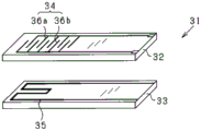
Fig. 2 is a perspective view showing a structure of a main part of a sensor element constituting the particulate matter sensor.
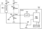
Fig. 3 is an electrical structural diagram of the particulate matter sensor.
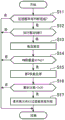
Fig. 4 is a flowchart showing the procedure of the 2 nd restoration process.
Fig. 5 is a sequence diagram showing a mode of the 2 nd recovery processing.
Fig. 6 is a diagram showing a relationship between a travel distance or a travel time and a standby time.
Fig. 7A is a graph showing a relationship between the amount of deposition of the particulate matter and the heating temperature of the heater.
Fig. 7B is a graph showing a relationship between the amount of deposition of the particulate matter and the heating time of the heater.
Detailed Description
The present embodiment exemplifies an exhaust gas treatment system of a vehicle including an engine. In an exhaust gas treatment system, a particulate matter filter (hereinafter, referred to as a "PM filter") as a filter device is provided in an exhaust pipe of an engine, and a PM sensor is provided downstream of the PM filter. In an exhaust gas treatment system, an abnormality of a PM filter is monitored based on an amount of PM adhering detected by a particulate matter sensor (hereinafter referred to as a "PM sensor").
Fig. 1 is a schematic configuration diagram of the present system. The engine 11 shown in fig. 1 is a diesel engine. The engine 11 is provided with a fuel injection valve 12 as an actuator related to the operation of the engine 11. A PM filter 14 is provided in an exhaust pipe 13 of the engine 11. A PM sensor 15 is provided on the downstream side of the PM filter 14.
The ECU20 includes a microcomputer including a CPU, ROM, RAM, and the like. The ECU20 executes control programs stored in the ROM to perform various controls of the engine 11 according to the operating state. Specifically, the ECU20 receives detection signals from the above-described sensors and the like, calculates the amount and timing of fuel injection based on the received detection signals, and controls the driving of the fuel injection valve 12. In the present embodiment, the ECU20 corresponds to a "sensor control device".
Next, the structure of the PM sensor 15 and the electrical structure of the PM sensor 15 will be described with reference to fig. 2 and 3. Fig. 2 is an exploded perspective view showing a main part structure of a sensor element 31 constituting the PM sensor 15. Fig. 3 is an electrical configuration diagram of the PM sensor 15.
As shown in fig. 2, the sensor element 31 has 2 insulating substrates 32 and 33 in the form of a long plate. The insulating substrate 32 is provided with a PM detection unit 34 for detecting the amount of PM deposited. In the present embodiment, the insulating substrate 32 corresponds to an "attached portion" to which conductive PM contained in exhaust gas is attached. Further, a heater portion 35 for heating the sensor element 31 is provided on the insulating substrate 33. The sensor element 31 is formed by laminating two layers of an insulating substrate 32 and an insulating substrate 33.
The insulating substrate 32 has a detection electrode 36a and a detection electrode 36b separated from each other on a substrate surface opposite to a surface laminated on the insulating substrate 33. The PM detection unit 34 is constituted by the pair of detection electrodes 36a and 36 b. The detection electrodes 36a and 36b each have a shape having a plurality of comb teeth (comb tooth shape). The detection electrodes 36a and 36b are arranged to face each other with a predetermined interval so that comb teeth are different from each other. In the present embodiment, the detection electrodes 36a and 36b correspond to "a pair of opposed electrodes". The heater unit 35 is formed of a heating element such as an electric heating wire.
The shape of the pair of detection electrodes 36a, 36b is not limited to the above shape. The detection electrodes 36a and 36b may have a curved shape. The detection electrodes 36a and 36b may be a pair of electrode portions each formed of 1 line, which are disposed in parallel and facing each other at a predetermined distance.
The PM sensor 15 has a holding portion (not shown) for holding the sensor element 31. The sensor element 31 is fixed to the exhaust pipe 13 with one end held by the holding portion. Specifically, the PM sensor 15 is attached to the exhaust pipe 13 as follows. The PM sensor 15 is provided such that a portion of the sensor element 31 including at least the PM detection unit 34 and the heater unit 35 is positioned inside the exhaust pipe 13. The PM sensor 15 is provided such that the insulating substrate 32 (the portion to which PM is attached) faces the upstream side of the flow of the exhaust gas. Thus, when the exhaust gas containing PM flows inside the exhaust pipe 13, PM adheres to the detection electrodes 36a and 36b of the insulating substrate 32 and the periphery thereof in the PM sensor 15. Further, the PM sensor 15 has a protective cover that covers the protruding portion of the sensor element 31.
The PM sensor 15 configured as described above detects the amount of PM deposited by the following method. When PM in the exhaust gas adheres to the insulating substrate 32 of the sensor element 31, the resistance value of the PM detection portion 34 (the resistance value between the detection electrode 36a and the detection electrode 36b) changes. The change in the resistance value corresponds to the amount of PM deposited. Thus, the PM sensor 15 detects the amount of adhesion of PM by using the change in the resistance value of the PM detection unit 34.
As shown in fig. 3, a sensor power supply 41 is connected to one end side of the PM detection unit 34 in the PM sensor 15. On the other hand, a shunt (shunt) resistor 42 is connected to the other end of the PM detection unit 34. The sensor power supply 41 is constituted by a constant voltage circuit or the like, and the constant voltage Vcc is 5V. In the case of such a configuration, the voltage divider circuit 40 is formed by the PM detection unit 34 and the shunt resistor 42, and the voltage at the intermediate point M between them is input to the ECU20 as the detection voltage Vpm of PM (the output value of the sensor). Specifically, in the PM detection unit 34, the resistance value Rpm changes according to the amount of adhesion of PM. The detection voltage Vpm of the PM changes according to the resistance value Rpm of the PM detection unit 34 and the resistance value Rs of the shunt resistance 42. The detection voltage Vpm of the PM is input to the microcomputer 44 via the a/D converter 43. The microcomputer 44 calculates the amount of adhesion of PM based on the detection voltage Vpm of PM. Further, the microcomputer 44 switches the on state and the off state of the sensor power source 41. Thus, the microcomputer 44 switches and controls the applied state and the non-applied state of the voltage to the pair of detection electrodes 36a and 36 b. In the case of such a configuration, when a voltage is applied to the pair of detection electrodes 36a and 36b, the PM is electrostatically guided to the PM detection section 34 and captured (electrostatically captured) by the insulating substrate 32. Then, the detection voltage Vpm of PM corresponding to the amount of adhesion of PM is detected.
A heater power supply 45 is connected to the heater portion 35 of the PM sensor 15. The heater power supply 45 is an in-vehicle battery or the like. The heater portion 35 is heated by power supplied from a heater power supply 45. A transistor 46 is connected as a switching element to the low potential side (lowside) of the heater portion 35. In the case of such a configuration, the microcomputer 44 turns on/off the transistor 46 to control the heating of the heater portion 35.
When the energization of the heater portion 35 is started in a state where the PM adheres to the insulating substrate 32 of the sensor element 31, the temperature of the adhering PM rises and the PM is forcibly burned. According to the sensor control device, the PM adhered to the insulating substrate 32 of the sensor element 31 is burned and removed by such forced combustion. The microcomputer 44 generates a request for forced combustion of PM and performs heating control of the heater unit 35, for example, after the engine 11 is started or after the operation is completed. In the PM sensor 15, forced combustion processing of PM is performed to recover the function of detecting the amount of PM deposited. Thus, the forced combustion process of the PM in the PM sensor 15 is also referred to as a sensor recovery process.
In addition, the ECU20 is provided with an EEPROM47 (registered trademark) as a spare memory for storing the learning value, the abnormality diagnostic value, and the like.
The ECU20 performs abnormality determination processing of the PM filter 14 based on the amount of PM deposited. Specifically, the ECU20 performs the sensor recovery process (1 st recovery process) after the engine 11 is started. The ECU20 controls the detection electrodes 36a and 36b to continuously apply a voltage until a predetermined period (predetermined voltage application period) elapses after the sensor recovery process ends. Thus, according to the sensor control device, the PM that has passed through the PM filter 14 is attached to the insulating substrate 32 of the sensor element 31 (electrostatic trapping) while the voltage is continuously applied to the detection electrodes 36a, 36 b. When the predetermined period has elapsed, the ECU20 determines whether or not the amount of PM deposited on the insulating substrate 32 is equal to or greater than an abnormality determination threshold Th1 (determination 1; deposition amount determination processing). When determining that the amount of PM deposited is equal to or greater than the abnormality determination threshold Th1 in the 1 st determination, the ECU20 determines that an abnormality such as damage or melting has occurred in the PM filter 14, and lights an abnormality warning lamp or the like to notify the user of the abnormality. In some cases, the operation of the engine 11 is restricted by fail safe (fail safe) processing. The abnormality determination threshold Th1 is set in advance as a value for determining whether or not the amount of PM that reaches the sensor element 31 is an appropriate amount.
According to the sensor control device, in order to perform the 1 st determination, the voltage is continuously applied to the detection electrodes 36a and 36b for a predetermined period (predetermined voltage application period) after the 1 st recovery process. Then, according to the sensor control device, the PM is attached to the insulating substrate 32 of the sensor element 31 (electrostatic trapping) while the voltage is continuously applied to the detection electrodes 36a and 36 b. However, according to the sensor control device, it is confirmed that PM contained in the exhaust gas adheres to the insulating substrate 32 except for the voltage application period. In such a case, it is considered that the amount of PM deposited increases particularly after a predetermined period of time has elapsed. That is, it is considered that the amount of PM adhering is larger when PM adheres due to the electrostatic trapping than when PM adheres without the electrostatic trapping. In such a state, it is considered that an excessive adhesion state of PM is likely to occur. Therefore, according to the sensor control device, PM remains on the insulating substrate 32 even if the 1 st recovery process is performed after the engine 11 is started, and as a result, the accuracy of determining the amount of PM deposited may be reduced.
Therefore, according to the sensor control device of the present embodiment, after the abnormality determination processing in which the 1 st determination is completed, the ECU20 performs the following control in order to suppress the amount of PM deposited from becoming excessive. Specifically, when a predetermined condition is satisfied after a predetermined period (a predetermined voltage application period) has elapsed, the ECU20 determines whether or not the amount of PM adhering is equal to or greater than an excessive amount determination threshold Th2 (determination 2; excessive adhesion determination processing). When determining that the amount of PM deposited is equal to or greater than the excessive determination threshold Th2 in the determination 2, the ECU20 performs a sensor recovery process (the recovery process 2) by heating the heater unit 35. The excessive determination threshold Th2 is set in advance to a value that allows PM combustion to be removed by the sensor recovery process (the 2 nd recovery process). In this case, the excess determination threshold Th2 is preferably smaller than the abnormality determination threshold Th1 (Th2 < Th 1).
Next, the sequence of the 2 nd recovery process executed by the ECU20 will be described with reference to fig. 4. This process is repeatedly executed by the ECU20 at predetermined intervals.
The ECU20 determines whether the abnormality determination process of the PM filter 14 is completed and determines that the PM filter 14 is functioning normally (step S11). In the present embodiment, when it is determined that the PM filter 14 is functioning normally, a flag indicating that the condition (normal) is set. Thus, when the flag is set, the ECU20 determines that: the abnormality determination process of the PM filter 14 is completed, and it is determined that the PM filter 14 is functioning normally (affirmative determination). On the other hand, when the flag is not set, the ECU20 determines that: the abnormality determination process of the PM filter 14 is not completed, or it is determined that the PM filter 14 is not functioning normally (negative determination).
If an affirmative determination is made in the determination processing of step S11 (yes), the ECU20 proceeds to the processing of step S12. On the other hand, if the determination process of step S11 is negative (no), the ECU20 ends the present process. Next, after the abnormality determination processing of the PM filter 14, the ECU20 determines whether or not a predetermined condition for determining whether or not to execute the 2 nd determination is satisfied (step S12). In the present embodiment, a predetermined standby time is set as a predetermined condition. Thus, the ECU20 determines that the predetermined condition for performing the 2 nd determination is satisfied (affirmative determination) every time a predetermined waiting time (e.g., 5 minutes) elapses after the abnormality determination processing of the PM filter 14. On the other hand, if the predetermined waiting time has not elapsed after the abnormality determination processing of the PM filter 14, the ECU20 determines that the predetermined condition for performing the 2 nd determination is not satisfied (negative determination).
If an affirmative determination is made in the determination processing of step S12 (yes), the ECU20 proceeds to the processing of step S13. On the other hand, if the determination process of step S12 is negative (no), the ECU20 ends the present process. Next, the ECU20 applies a voltage to the detection electrodes 36a and 36b temporarily (for example, for less than 1 second) to calculate the amount of PM deposited (step S13). Next, the ECU20 determines whether or not the amount of PM deposited is equal to or greater than the excess determination threshold Th2 (step S14). The ECU20 makes an affirmative determination when the amount of PM deposited is equal to or greater than the excessive determination threshold Th 2. On the other hand, the ECU20 makes a negative determination when the amount of PM deposited is less than the excessive determination threshold Th 2.
If an affirmative determination is made in the determination processing of step S14 (yes), the ECU20 increases the number of times that it is determined that the amount of PM adhering is equal to or greater than the excessive determination threshold Th2, and proceeds to the processing of step S15. On the other hand, if the determination process of step S14 is negative (no), the ECU20 ends the present process. Next, the ECU20 performs the 2 nd recovery process of the PM sensor 15 by the heating of the heater section 35 (step S15). In the 2 nd recovery process, the heater unit 35 is heated in accordance with a predetermined heating temperature and heating time, and PM adhering to the sensor element 31 is burned and removed. In the present embodiment, the 1 st recovery process is a process for removing all the PM adhering to the insulating substrate 32 of the sensor element 31 by combustion. In contrast, the 2 nd recovery process is a process for suppressing the excessive adhesion state of the PM after the 1 st recovery process. Therefore, the heating temperature and the heating time of the heater portion 35 in the 2 nd recovery process may be the same as those in the 1 st recovery process, but the heating time may be set shorter than that in the 1 st recovery process. The heating temperature may be set to be low.
After the abnormality determination process of the PM filter 14, the ECU20 determines whether or not the cumulative count determined to be equal to or greater than the excessive determination threshold Th2 of the amount of PM deposited has reached a predetermined count Th3 (e.g., 2 counts) (step S16). The ECU20 makes an affirmative determination when the accumulated number of times reaches the predetermined number of times Th 3. On the other hand, the ECU20 makes a negative determination when the accumulated number of times does not reach the predetermined number of times Th 3. If an affirmative determination is made in the determination processing of step S16 (yes), the ECU20 proceeds to the processing of step S17. On the other hand, if the determination process of step S16 is negative (no), the ECU20 ends the present process. The ECU20 performs the 1 st recovery process of the PM sensor 15 and requests the re-execution of the abnormality determination process of the PM filter 14 (step S17).
Next, a mode of the 2 nd recovery processing will be described with reference to fig. 5. In fig. 5, it is assumed that the IG switch is switched to the on state immediately after the engine 11 is started.
At time t11, engine 11 is started in association with the switching of the IG switch to the on state. This increases the temperature inside the exhaust pipe 13, and the condensed water inside the exhaust pipe 13 evaporates. Since the condensed water in the exhaust pipe 13 is evaporated, at time t12 after the predetermined drying period has elapsed, the energization of the heater portion 35 is started, and the 1 st recovery process is performed. At this time, the temperature of the PM sensor 15 rises, and PM adhering to the insulating substrate 32 of the sensor element 31 is burned and removed. At time t13, the energization of the heater portion 35 is stopped, and the 1 st recovery process is completed. Thereby, the temperature of the PM sensor 15 decreases. After time t14 when the predetermined cooling period of the PM sensor 15 has elapsed, the voltage is continuously applied to the detection electrodes 36a and 36b until the predetermined period (predetermined voltage application period) has elapsed. Then, the PM that has passed through the PM filter 14 is attached to the insulating substrate 32 (electrostatic trapping) while a voltage is applied to the detection electrodes 36a and 36 b. At this time, the amount of PM deposited increases. At time t15 after the elapse of the predetermined period, a 1 st determination is made as to whether or not the amount of PM deposited on the insulating substrate 32 is equal to or greater than the abnormality determination threshold Th 1. As a result, when it is determined that the amount of PM deposited is less than the abnormality determination threshold Th1, the abnormality determination process of the PM filter 14 is completed.
After time t15, a voltage is applied to the detection electrodes 36a and 36b once every time a predetermined waiting time elapses, and the amount of adhesion of PM is obtained. In the present embodiment, the elapse of the standby time means that a predetermined condition for determining whether or not to execute the determination 2 is satisfied. Thus, after time t15, every time a predetermined standby time elapses, the 2 nd determination is made as to whether or not the amount of PM adhering is equal to or greater than the excessive determination threshold Th 2. As a result, when it is determined that the amount of PM deposited is equal to or greater than the excessive determination threshold Th2, the energization of the heater unit 35 is started, and the 2 nd recovery process is performed. At this time, the temperature of the PM sensor 15 rises, and PM adhering to the insulating substrate 32 of the sensor element 31 is burned and removed. At time t17, the energization of the heater portion 35 is stopped, and the 2 nd recovery process is completed. Thereby, the temperature of the PM sensor 15 decreases.
As described above, according to the sensor control device of the present embodiment, the following advantageous effects can be obtained.
The sensor control device of the present embodiment determines whether or not the amount of PM deposited is equal to or greater than the excess determination threshold Th2 when a predetermined condition is satisfied, other than the voltage application period (abnormality determination period of the PM filter 14) of the detection electrodes 36a and 36 b. As a result, when determining that the amount of PM deposited is equal to or greater than the excessive determination threshold Th2, the sensor control device performs the 2 nd recovery process of the PM sensor 15 by heating the heater unit 35. Therefore, according to the sensor control device of the present embodiment, even if PM adheres to the insulating substrate 32 other than during the voltage application period, the excessive adhesion state of PM is not left as it is. Thus, according to the sensor control device, the excessive PM remaining after the 1 st recovery processing of the PM sensor 15 is suppressed, and the adhesion amount of PM can be appropriately determined.
The sensor control device of the present embodiment determines whether or not the amount of PM adhering is equal to or greater than the excessive determination threshold Th2 (performs determination 2) every time a predetermined standby time elapses after the abnormality determination process of the PM filter 14. The sensor control device performs the 2 nd recovery process when determining that the amount of PM deposited is equal to or greater than the excessive determination threshold Th2 after the voltage application period of the detection electrodes 36a and 36b has elapsed. Therefore, according to the sensor control device of the present embodiment, the excessive adhesion state of PM is not left as it is after the predetermined voltage application period in which the excessive adhesion state of PM is likely to occur.
The sensor control device of the present embodiment determines the amount of PM deposited by applying a voltage to the detection electrodes 36a and 36b once every time a predetermined standby time elapses after the abnormality determination process of the PM filter 14. As described above, since the voltage application to the detection electrodes 36a and 36b is temporary, the sensor control device according to the present embodiment can determine the amount of PM deposited while suppressing power consumption associated with the voltage application. Further, according to the sensor control device, it is possible to suppress the PM from being electrostatically trapped, and to suppress an increase in the amount of adhesion of the PM.
The sensor control device of the present embodiment determines the following after the abnormality determination processing of the PM filter 14: it is determined whether or not the number of accumulations of the PM adhering amount equal to or greater than the excessive determination threshold Th2 has reached the predetermined number Th 3. As a result, when determining that the cumulative count has reached the predetermined count Th3, the sensor control device performs the 1 st recovery process of the PM sensor 15 and the abnormality determination process of the PM filter 14. At this time, in a situation where the 2 nd recovery process of the PM sensor 15 is repeatedly performed, it is determined that it is necessary to confirm whether the PM filter 14 is functioning normally, and an abnormality determination is performed. Therefore, according to the sensor control device of the present embodiment, the presence or absence of an abnormality of the PM filter 14 can be appropriately grasped.
It is considered that, when the PM filter 14 is normal, the amount of PM deposited is maintained in a relatively small state as compared with the abnormal state. In such a state, when the PM remaining on the insulating substrate 32 of the sensor element 31 is considered to be removed, the excess determination threshold Th2 is preferably set to a value smaller than the abnormality determination threshold Th 1. Therefore, according to the sensor control device of the present embodiment, the excess determination threshold Th2 is set to a value smaller than the abnormality determination threshold Th 1. Thus, according to the sensor control device, the effect of suppressing the PM remaining after the 1 st recovery process of the PM sensor 15 is improved.
(other embodiments)
The above embodiment can be modified as follows, for example.
The sensor control device may be configured to perform the 2 nd determination of determining the excessive adhesion state of PM after the engine 11 is started and before the first 1 st recovery process is executed. As a result, when it is determined that the amount of PM deposited is equal to or greater than the excessive amount determination threshold Th2, the first 1 st recovery process may be performed after the engine 11 is started, and the 2 nd recovery process for eliminating the excessive state of PM deposited may be performed.
It is considered that, in a situation where PM remains on the insulating substrate 32 of the sensor element 31 after the 2 nd recovery process, the amount of PM deposited increases cumulatively as the travel distance and the travel time of the vehicle are longer, and the excessive deposition state of PM is more likely to occur. In view of this, the sensor control device may be configured to acquire a travel distance or a travel time (vehicle information) of the vehicle, and set a standby time as a predetermined condition for determining whether or not to execute the 2 nd determination, based on the acquired vehicle information. In this case, as shown in fig. 6, the waiting time until the determination of the 2 nd determination may be set to be shorter as the travel distance or the travel time of the vehicle is longer. Thus, in a situation where an excessive adhesion state of PM is likely to occur due to the travel distance or the length of travel time of the vehicle, the frequency of making the 2 nd determination of whether or not to execute the 2 nd recovery process of the PM sensor 15 becomes high. Therefore, according to the sensor control device, the effect of suppressing the excessive adhesion state of PM from being left as it is improved. In addition, the sensor control device may be configured to set the waiting time in accordance with the travel distance and the travel time of the vehicle. As described above, the sensor control device may be configured to include an information acquisition unit that acquires vehicle information including at least one of a travel distance and a travel time of the vehicle, and a predetermined condition changing unit that changes the predetermined condition for performing the determination of the second determination based on the vehicle information.
The sensor control device may be configured to set the heating temperature and the heating time of the heater unit 35 used in the 2 nd recovery process of the PM sensor 15 in accordance with the amount of adhesion of PM when it is determined that the amount of adhesion of PM is equal to or greater than the excess determination threshold Th 2. In this case, as shown in fig. 7A and 7B, the heating temperature may be set higher or the heating time may be set longer as the amount of PM deposited increases. Thus, according to the sensor control device, the 2 nd recovery process can be appropriately performed in consideration of the amount of adhesion of PM. As described above, the sensor control device may be configured to include a process condition changing unit configured to change the process condition of the 2 nd recovery process in accordance with the amount of deposition when it is determined that the amount of deposition of the particulate matter is equal to or greater than the predetermined value.
In the above embodiment, the standby time is determined in advance as the predetermined condition for determining whether or not to execute the 2 nd determination, and the 2 nd determination is performed every time the predetermined standby time elapses after the abnormality determination processing. The sensor control device may be configured to determine the travel distance in advance as a predetermined condition for performing the determination 2, and perform the determination 2 every time the predetermined travel distance is reached after the abnormality determination processing.
In the above embodiment, the heating time of the heater unit 35 used in the 2 nd recovery process is set to be shorter than that in the 1 st recovery process, but the present invention is not limited thereto. The sensor control device may be configured to set the heating time of the heater portion 35 in the 2 nd recovery process to be longer than in the 1 st recovery process. In addition, the sensor control device may be configured to set the heating temperature of the heater portion 35 at the time of the 2 nd recovery process higher than that of the 1 st recovery process.
When PM in the exhaust gas adheres to the insulating substrate 32 of the sensor element 31, the resistance value of the PM detection unit 34 (the resistance value between the detection electrode 36a and the detection electrode 36b) changes. In the above embodiment, the amount of adhesion of PM is detected by using the change in the resistance value of the PM detection unit 34, but the present invention is not limited thereto. The sensor control device may be configured to detect the amount of PM deposited by using a change in capacitance.
Description of the symbols
11 … engine (internal combustion engine), 13 … exhaust pipe (exhaust passage), 15 … PM sensor (sensor), 20 … ECU (sensor control device), 32 … insulating substrate (attached part), 35 … heater part (heater), 36a, 36b … detection electrode (a pair of opposed electrodes)
Claims (9)
1. A sensor control device (20) for a sensor (15),
the sensor has:
an attached section (32) for attaching conductive particulate matter contained in the exhaust gas;
a pair of opposed electrodes (36a, 36b) provided on the attached portion so as to be separated from each other; and
a heater (35) for heating the adhered part,
a sensor which is provided in an exhaust passage (13) of an internal combustion engine (11) and detects the amount of deposition of the particulate matter on the basis of the detection signal, the sensor outputting a detection signal corresponding to the amount of deposition of the particulate matter,
the sensor control device (20) is provided with:
a 1 st recovery unit that performs a 1 st recovery process of the sensor by heating of the heater after the internal combustion engine is started;
a 1 st determination unit configured to determine an amount of the particulate matter adhering to the adhered portion when the predetermined period has elapsed since the particulate matter was adhered to the adhered portion while the voltage was continuously applied to the counter electrode for a predetermined period after the 1 st recovery process was performed;
a 2 nd determination unit configured to determine whether or not an amount of the particulate matter deposited on the deposited portion is equal to or greater than a predetermined value when a predetermined condition is satisfied other than the predetermined period; and
a 2 nd recovery unit that performs a 2 nd recovery process of the sensor by heating the sensor with the heater when the 2 nd determination unit determines that the amount of the particulate matter deposited is equal to or greater than a predetermined value,
the sensor control device (20) is characterized in that,
the 1 st recovery unit performs the 1 st recovery process at the beginning of the start of the operation of the internal combustion engine,
the 2 nd determination unit determines the amount of the particulate matter deposited, every time the predetermined condition is satisfied after the determination by the 1 st determination unit.
2. The sensor control apparatus of claim 1,
when the number of times that the amount of the particulate matter deposited is equal to or greater than the predetermined value is determined to have reached the predetermined number of times by the 2 nd determination unit, the 1 st recovery process by the 1 st recovery unit and the amount of deposition determination process by the 1 st determination unit are performed.
3. A sensor control device (20) for a sensor (15),
the sensor has:
an attached section (32) for attaching conductive particulate matter contained in the exhaust gas;
a pair of opposed electrodes (36a, 36b) provided on the attached portion so as to be separated from each other; and
a heater (35) for heating the adhered part,
a sensor which is provided in an exhaust passage (13) of an internal combustion engine (11) and detects the amount of deposition of the particulate matter on the basis of the detection signal, the sensor outputting a detection signal corresponding to the amount of deposition of the particulate matter,
the sensor control device (20) is provided with:
a 1 st recovery unit that performs a 1 st recovery process of the sensor by heating of the heater after the internal combustion engine is started;
a 1 st determination unit configured to determine an amount of the particulate matter adhering to the adhered portion when the predetermined period has elapsed since the particulate matter was adhered to the adhered portion while the voltage was continuously applied to the counter electrode for a predetermined period after the 1 st recovery process was performed;
a 2 nd determination unit configured to determine whether or not an amount of the particulate matter deposited on the deposited portion is equal to or greater than a predetermined value when a predetermined condition is satisfied other than the predetermined period; and
a 2 nd recovery unit that performs a 2 nd recovery process of the sensor by heating the sensor with the heater when the 2 nd determination unit determines that the amount of the particulate matter deposited is equal to or greater than a predetermined value,
the sensor control device (20) is characterized in that,
when the number of times that the amount of the particulate matter deposited is equal to or greater than the predetermined value is determined to have reached the predetermined number of times by the 2 nd determination unit, the 1 st recovery process by the 1 st recovery unit and the amount of deposition determination process by the 1 st determination unit are performed.
4. The sensor control apparatus according to claim 1 or 3,
suitable for use in a vehicle provided with the sensor described above,
the disclosed device is provided with:
an information acquisition unit that acquires vehicle information including at least one of a travel distance and a travel time of the vehicle; and
and a predetermined condition changing unit that changes the predetermined condition based on the vehicle information.
5. A sensor control device (20) for a sensor (15),
the sensor has:
an attached section (32) for attaching conductive particulate matter contained in the exhaust gas;
a pair of opposed electrodes (36a, 36b) provided on the attached portion so as to be separated from each other; and
a heater (35) for heating the adhered part,
a sensor which is provided in an exhaust passage (13) of an internal combustion engine (11) and detects the amount of deposition of the particulate matter on the basis of the detection signal, the sensor outputting a detection signal corresponding to the amount of deposition of the particulate matter,
the sensor control device (20) is provided with:
a 1 st recovery unit that performs a 1 st recovery process of the sensor by heating of the heater after the internal combustion engine is started;
a 1 st determination unit configured to determine an amount of the particulate matter adhering to the adhered portion when the predetermined period has elapsed since the particulate matter was adhered to the adhered portion while the voltage was continuously applied to the counter electrode for a predetermined period after the 1 st recovery process was performed;
a 2 nd determination unit configured to determine whether or not an amount of the particulate matter deposited on the deposited portion is equal to or greater than a predetermined value when a predetermined condition is satisfied other than the predetermined period; and
a 2 nd recovery unit that performs a 2 nd recovery process of the sensor by heating the sensor with the heater when the 2 nd determination unit determines that the amount of the particulate matter deposited is equal to or greater than a predetermined value,
the sensor control device (20) is characterized by being applied to a vehicle provided with the sensor,
the disclosed device is provided with:
an information acquisition unit that acquires vehicle information including at least one of a travel distance and a travel time of the vehicle; and
and a predetermined condition changing unit that changes the predetermined condition based on the vehicle information.
6. The sensor control apparatus according to claim 1, 3 or 5,
the 2 nd determination unit determines the amount of deposition of the particulate matter by applying a voltage to the counter electrode temporarily whenever the predetermined condition is satisfied.
7. The sensor control apparatus according to claim 1, 3 or 5,
and a processing condition changing unit configured to change the processing condition of the 2 nd recovery process based on the deposition amount when the 2 nd determination unit determines that the deposition amount of the particulate matter is equal to or greater than a predetermined value.
8. The sensor control apparatus according to claim 1, 3 or 5,
the 1 st judging unit judges whether or not the amount of the particulate matter adhering to the sensor is equal to or larger than an abnormality judgment threshold value in order to judge whether or not the amount of the particulate matter reaching the sensor is an appropriate amount,
the predetermined value relating to the 2 nd determination unit is set to a value smaller than the abnormality determination threshold.
9. The sensor control apparatus according to claim 1, 3 or 5,
the sensor is provided on a downstream side of a filter device that traps the particulate matter in an exhaust passage of the internal combustion engine,
the 1 st determination unit determines whether or not there is an abnormality in the filter device based on the amount of the particulate matter deposited.
Applications Claiming Priority (3)
| Application Number | Priority Date | Filing Date | Title |
|---|---|---|---|
| JP2016007835A JP6439706B2 (en) | 2016-01-19 | 2016-01-19 | Sensor control device |
| JP2016-007835 | 2016-01-19 | ||
| PCT/JP2017/001452 WO2017126516A1 (en) | 2016-01-19 | 2017-01-18 | Sensor control device |
Publications (2)
| Publication Number | Publication Date |
|---|---|
| CN108474280A CN108474280A (en) | 2018-08-31 |
| CN108474280B true CN108474280B (en) | 2020-05-12 |
Family
ID=59362255
Family Applications (1)
| Application Number | Title | Priority Date | Filing Date |
|---|---|---|---|
| CN201780006661.7A Expired - Fee Related CN108474280B (en) | 2016-01-19 | 2017-01-18 | Sensor control device |
Country Status (5)
| Country | Link |
|---|---|
| US (1) | US10871117B2 (en) |
| JP (1) | JP6439706B2 (en) |
| CN (1) | CN108474280B (en) |
| DE (1) | DE112017000421T5 (en) |
| WO (1) | WO2017126516A1 (en) |
Families Citing this family (1)
| Publication number | Priority date | Publication date | Assignee | Title |
|---|---|---|---|---|
| JP7087530B2 (en) * | 2018-03-23 | 2022-06-21 | コベルコ建機株式会社 | Exhaust gas abnormality detector |
Citations (4)
| Publication number | Priority date | Publication date | Assignee | Title |
|---|---|---|---|---|
| CN101008630A (en) * | 2006-01-23 | 2007-08-01 | 株式会社电装 | Gas sensing member used for gas sensor and method of manufacturing the member |
| WO2010103834A1 (en) * | 2009-03-11 | 2010-09-16 | 本田技研工業株式会社 | Failure detection device for exhaust gas purification filter |
| JP2012127268A (en) * | 2010-12-15 | 2012-07-05 | Toyota Motor Corp | Control device for internal combustion engine |
| JP2012149525A (en) * | 2011-01-17 | 2012-08-09 | Mazda Motor Corp | Exhaust emission control device of engine |
Family Cites Families (4)
| Publication number | Priority date | Publication date | Assignee | Title |
|---|---|---|---|---|
| JPS5115873B2 (en) | 1972-01-14 | 1976-05-20 | ||
| JP5115873B2 (en) | 2010-12-08 | 2013-01-09 | 株式会社デンソー | Particulate filter failure detection device |
| USRE47116E1 (en) | 2011-03-15 | 2018-11-06 | Toyota Jidosha Kabushiki Kaisha | Control apparatus for internal combustion engine |
| RU2555430C1 (en) | 2011-08-04 | 2015-07-10 | Тойота Дзидося Кабусики Кайся | Control unit for internal combustion engine |
-
2016
- 2016-01-19 JP JP2016007835A patent/JP6439706B2/en active Active
-
2017
- 2017-01-18 CN CN201780006661.7A patent/CN108474280B/en not_active Expired - Fee Related
- 2017-01-18 US US16/070,894 patent/US10871117B2/en active Active
- 2017-01-18 WO PCT/JP2017/001452 patent/WO2017126516A1/en active Application Filing
- 2017-01-18 DE DE112017000421.7T patent/DE112017000421T5/en not_active Withdrawn
Patent Citations (4)
| Publication number | Priority date | Publication date | Assignee | Title |
|---|---|---|---|---|
| CN101008630A (en) * | 2006-01-23 | 2007-08-01 | 株式会社电装 | Gas sensing member used for gas sensor and method of manufacturing the member |
| WO2010103834A1 (en) * | 2009-03-11 | 2010-09-16 | 本田技研工業株式会社 | Failure detection device for exhaust gas purification filter |
| JP2012127268A (en) * | 2010-12-15 | 2012-07-05 | Toyota Motor Corp | Control device for internal combustion engine |
| JP2012149525A (en) * | 2011-01-17 | 2012-08-09 | Mazda Motor Corp | Exhaust emission control device of engine |
Also Published As
| Publication number | Publication date |
|---|---|
| JP2017129038A (en) | 2017-07-27 |
| US20190032588A1 (en) | 2019-01-31 |
| CN108474280A (en) | 2018-08-31 |
| WO2017126516A1 (en) | 2017-07-27 |
| US10871117B2 (en) | 2020-12-22 |
| JP6439706B2 (en) | 2018-12-19 |
| DE112017000421T5 (en) | 2018-10-11 |
Similar Documents
| Publication | Publication Date | Title |
|---|---|---|
| JP5408069B2 (en) | Sensor control device and exhaust treatment system including the same | |
| US9534524B1 (en) | Dual rate diesel particulate filter leak monitor | |
| JP5278615B2 (en) | Particulate matter detection device for internal combustion engine | |
| JP5348089B2 (en) | Sensor control device | |
| CN108071459B (en) | Abnormality diagnosis device for exhaust gas purification system | |
| JP5531849B2 (en) | Sensor control device | |
| JP5408070B2 (en) | Sensor control device | |
| JP6137229B2 (en) | Particulate filter abnormality diagnosis device | |
| JP2010275917A (en) | Failure determination device for particulate matter detection means | |
| JP2016056701A (en) | Abnormality diagnosis device for particulate filter | |
| JP6361918B2 (en) | Filter failure detection device | |
| JP6090293B2 (en) | Filter function diagnostic device | |
| RU2690016C2 (en) | Method (embodiments) and system for detection of solid particles in exhaust gases | |
| US10900882B2 (en) | Electrostatic soot sensor | |
| JP5533477B2 (en) | Engine control device | |
| CN108474280B (en) | Sensor control device | |
| JP5488451B2 (en) | Fine particle detector | |
| JP2012077668A (en) | Sensor control device | |
| JP2012037369A (en) | Sensor controller | |
| WO2017002828A1 (en) | Plasma reactor applied voltage control device and plasma reactor control device | |
| CN108350778B (en) | Device for determining whether or not abnormality has occurred in filter device | |
| JP2011089791A (en) | Particulate detector | |
| US11293849B2 (en) | Method for operating a sensor for detecting particles in a measuring gas | |
| JP2020101393A (en) | Particulate matter detection device | |
| WO2020162281A1 (en) | Particulate matter detection sensor |
Legal Events
| Date | Code | Title | Description |
|---|---|---|---|
| PB01 | Publication | ||
| PB01 | Publication | ||
| SE01 | Entry into force of request for substantive examination | ||
| SE01 | Entry into force of request for substantive examination | ||
| GR01 | Patent grant | ||
| GR01 | Patent grant | ||
| CF01 | Termination of patent right due to non-payment of annual fee |
Granted publication date: 20200512 |
|
| CF01 | Termination of patent right due to non-payment of annual fee |