WO2017126507A1 - コネクタハウジング - Google Patents
コネクタハウジング Download PDFInfo
- Publication number
- WO2017126507A1 WO2017126507A1 PCT/JP2017/001423 JP2017001423W WO2017126507A1 WO 2017126507 A1 WO2017126507 A1 WO 2017126507A1 JP 2017001423 W JP2017001423 W JP 2017001423W WO 2017126507 A1 WO2017126507 A1 WO 2017126507A1
- Authority
- WO
- WIPO (PCT)
- Prior art keywords
- connector housing
- fitting
- housing according
- volume occupied
- fitting portion
- Prior art date
- Legal status (The legal status is an assumption and is not a legal conclusion. Google has not performed a legal analysis and makes no representation as to the accuracy of the status listed.)
- Ceased
Links
Images


Classifications
-
- H—ELECTRICITY
- H01—ELECTRIC ELEMENTS
- H01R—ELECTRICALLY-CONDUCTIVE CONNECTIONS; STRUCTURAL ASSOCIATIONS OF A PLURALITY OF MUTUALLY-INSULATED ELECTRICAL CONNECTING ELEMENTS; COUPLING DEVICES; CURRENT COLLECTORS
- H01R13/00—Details of coupling devices of the kinds covered by groups H01R12/70 or H01R24/00 - H01R33/00
- H01R13/46—Bases; Cases
-
- H—ELECTRICITY
- H01—ELECTRIC ELEMENTS
- H01R—ELECTRICALLY-CONDUCTIVE CONNECTIONS; STRUCTURAL ASSOCIATIONS OF A PLURALITY OF MUTUALLY-INSULATED ELECTRICAL CONNECTING ELEMENTS; COUPLING DEVICES; CURRENT COLLECTORS
- H01R13/00—Details of coupling devices of the kinds covered by groups H01R12/70 or H01R24/00 - H01R33/00
- H01R13/46—Bases; Cases
- H01R13/516—Means for holding or embracing insulating body, e.g. casing, hoods
- H01R13/518—Means for holding or embracing insulating body, e.g. casing, hoods for holding or embracing several coupling parts, e.g. frames
-
- H—ELECTRICITY
- H01—ELECTRIC ELEMENTS
- H01R—ELECTRICALLY-CONDUCTIVE CONNECTIONS; STRUCTURAL ASSOCIATIONS OF A PLURALITY OF MUTUALLY-INSULATED ELECTRICAL CONNECTING ELEMENTS; COUPLING DEVICES; CURRENT COLLECTORS
- H01R13/00—Details of coupling devices of the kinds covered by groups H01R12/70 or H01R24/00 - H01R33/00
- H01R13/46—Bases; Cases
- H01R13/50—Bases; Cases formed as an integral body
-
- H—ELECTRICITY
- H01—ELECTRIC ELEMENTS
- H01R—ELECTRICALLY-CONDUCTIVE CONNECTIONS; STRUCTURAL ASSOCIATIONS OF A PLURALITY OF MUTUALLY-INSULATED ELECTRICAL CONNECTING ELEMENTS; COUPLING DEVICES; CURRENT COLLECTORS
- H01R13/00—Details of coupling devices of the kinds covered by groups H01R12/70 or H01R24/00 - H01R33/00
- H01R13/46—Bases; Cases
- H01R13/514—Bases; Cases composed as a modular blocks or assembly, i.e. composed of co-operating parts provided with contact members or holding contact members between them
-
- H—ELECTRICITY
- H01—ELECTRIC ELEMENTS
- H01R—ELECTRICALLY-CONDUCTIVE CONNECTIONS; STRUCTURAL ASSOCIATIONS OF A PLURALITY OF MUTUALLY-INSULATED ELECTRICAL CONNECTING ELEMENTS; COUPLING DEVICES; CURRENT COLLECTORS
- H01R25/00—Coupling parts adapted for simultaneous co-operation with two or more identical counterparts, e.g. for distributing energy to two or more circuits
-
- H—ELECTRICITY
- H01—ELECTRIC ELEMENTS
- H01R—ELECTRICALLY-CONDUCTIVE CONNECTIONS; STRUCTURAL ASSOCIATIONS OF A PLURALITY OF MUTUALLY-INSULATED ELECTRICAL CONNECTING ELEMENTS; COUPLING DEVICES; CURRENT COLLECTORS
- H01R25/00—Coupling parts adapted for simultaneous co-operation with two or more identical counterparts, e.g. for distributing energy to two or more circuits
- H01R25/006—Coupling parts adapted for simultaneous co-operation with two or more identical counterparts, e.g. for distributing energy to two or more circuits the coupling part being secured to apparatus or structure, e.g. duplex wall receptacle
Definitions
- the present invention relates to an electrical connector housing, and more particularly to a connector housing that can reduce warpage when the dimension in the width direction is large.
- a connector housing which is a constituent element of an electrical connector, is manufactured by injection molding an electrically insulating synthetic resin, and the injection molded molded body is warped by stress generated inside the molded body.
- the connector housing is warped, there is a problem that the accuracy of assembly to the housing is not satisfied, or the fitting with the mating connector housing cannot be performed.
- Patent Document 1 it has been proposed to make the wall portion where the warpage occurs thicker than other portions.
- Increasing the wall thickness as in Patent Document 1 is an effective technique for reducing the warpage of the connector housing, but depending on the use of the connector housing, the thickness may not be sufficiently reduced by the wall thickness.
- the connector housing has a large size in the width direction and includes a plurality of fitting portions that are fitted to the mating electrical connector (connector housing), it is difficult to compensate for warpage.
- an object of this invention is to provide the connector housing which can reduce curvature even if the dimension of the width direction is large and it is provided with the some fitting part.
- the connector housing of the present invention includes a fitting portion in which a plurality of fitting hoods are arranged in the width direction in front of the mating connector, and a rear structure portion arranged behind the fitting portion.
- the rear structure portion according to the present invention includes a real structure portion provided between each of the two adjacent fitting hoods, and a notch provided between the two adjacent real structure portions. .
- the connector housing of the present invention by providing a plurality of actual structure portions as the rear structure portions, the front and rear volumes are approximated, and warpage occurring in the connector housing after injection molding is reduced.
- the connector housing of the present invention balances the force that contracts in the direction perpendicular to the flow direction of the resin injected into the mold cavity by providing a notch in addition to the actual structure portion, and injects the resin. This reduces the warpage that occurs in the connector housing after molding.
- the fitting portion has a plurality of fitting hoods arranged symmetrically in the width direction
- the rear structure portion has a plurality of actual structure portions and a plurality of notches arranged symmetrically in the width direction. It is preferred that In the connector housing of the present invention, it is preferable that each actual structure portion has a plurality of lightening portions opened at the tip and is formed point-symmetrically. By these, the curvature which arises after injection molding can be reduced more.
- V1: V2 1.0: 1.0 to 1.4: 1.0 is satisfied. Is preferable for reducing warpage.
- each of the actual structural portions overlaps with the two fitting hoods corresponding in the width direction y. This is also preferable for reducing warpage.
- the first feature that approximates the front and rear volumes, and the direction perpendicular to the direction in which the resin injected into the mold cavity flows.
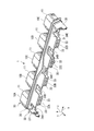
- FIG. 1 It is a perspective view which shows the connector housing which concerns on embodiment of this invention.
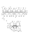
- the connector housing of FIG. 1 is shown, (a) is a top view, (b) is a front view, (c) is a bottom view. It is a figure for demonstrating the effect
- the connector housing 1 is a female housing that holds a plurality of terminals (not shown) (not shown), and is integrally formed by injection molding a resin.
- the resin material which comprises the connector housing 1 is arbitrary, in this embodiment, the fiber reinforced resin (Fiber Reinforced Plastics: FRP) shall be used.
- the connector housing 1 is a cover that covers a fitting portion 10 into which a mating electrical connector is fitted, a holding portion 20 that holds a terminal, and a terminal that is pulled out from the holding portion 20. 30.
- the connector housing 1 suppresses the occurrence of warping by specifying the configuration of the holding portion 20.
- a one-dot chain line B (warp B) in FIG. 3A the warp of the connector housing 1 is recessed at the center in the width direction y of the fitting portion 10 and at the center of the cover 30 in the width direction y. It occurs along the front-rear direction x so as to be convex.
- the front-rear direction x is the front-rear direction x
- the y-axis is the width direction y
- the z-axis direction is the height direction z.
- the side where the connector is fitted is defined as the front
- the side where the cover 30 is provided and the terminal is drawn out is defined as the rear.
- the fitting portion 10 includes five fitting portions arranged in the width direction y, that is, fitting portions 10A to 10E.
- the five fitting portions are arranged at equal intervals in the width direction y around the fitting portion 10C.
- the fitting portions 10A to 10E are formed with the same structure and dimensions.
- Each of the fitting portions 10A to 10E includes a fitting hood 11 having a rectangular tube shape, and a receiving space 13 that occupies a space from the opening 12 positioned in front of the fitting hood 11 to the holding portion 20. I have.
- the holding unit 20 includes a holding wall 21 and a holding hole 25 formed in the holding wall 21.
- the terminal is held in the holding wall 21 by being press-fitted into the holding hole 25.
- the holding wall 21 has a thickness that allows a press-fitting allowance sufficient to hold a press-fitted contact (not shown), and faces the front surface facing forward and the rear. It has a back surface.
- the holding hole 25 is formed through the front surface and the back surface corresponding to the position of the terminal to be held.
- the holding wall 21 in which the holding hole 25 is formed is provided corresponding to each fitting hood 11 of the fitting portion 10A to the fitting portion 10E.
- the cover 30 that is connected to the rear of the holding portion 20 and forms the rear structure portion includes an upper structure 31, a left side wall 37 and a right side wall 38 that are connected to the upper structure 31 on both sides in the width direction y.
- a terminal that is drawn rearward from the holding unit 20 is disposed inside 30.
- the upper structure 31 includes a plurality of actual structure portions 32 provided at intervals in the width direction y, and notches 34 provided between adjacent actual structure portions 32.
- the real structure parts are collectively referred to, they are represented as real structure parts 32, and when the respective real structure parts are distinguished, they are represented as real structure parts 32A, 32B, 32C, 32D.
- the notches 34 are distinguished as notches 34A, 34B, 34C, 34D, and 34E.
- the actual structural portions 32A, 32B, 32C, and 32D are arranged symmetrically in the width direction y.
- Solid structure portion 32 the volume of the resin constituting the fitting portion 10 which is disposed in front by a retaining portion 20 as a boundary, is provided in order to approximate the volume of the resin constituting the cover 30 is disposed rearward .
- the connector housing 1 in this embodiment reduces the warp after injection molding by balancing the volumes of the fitting portion 10 and the cover 30.
- Each real structure portion 32 has a rectangular parallelepiped shape extending rearward from the holding portion 20, and four hollow portions 33 (openings) having rectangular openings at the tips thereof are arranged in a lattice shape. Has been placed.
- each of the actual structural portions 32 has a point-symmetric shape along the yz plane in FIG. 1 and the thickness around the thinned portion 33 is uniform.
- the present invention does not exclude the solid actual structure portion 32 and is made of a resin material that forms the connector housing 1 as long as the volume with the fitting portion 10 can be balanced. As long as the form is not asked.
- the notch 34 reduces the occurrence of warpage by controlling the flow of the molten resin so that warpage is less likely to occur when the connector housing 1 is manufactured by injection molding.
- the notches 34 are provided between the left side wall 37 and the actual structure portion 32A, between the actual structure portion 32A and the actual structure portion 32B, between the actual structure portion 32B and the actual structure portion 32C, and between the actual structure portion 32C and the actual structure. It is provided between the part 32D and between the actual structure part 32D and the right side wall 38.
- the notches 34 are arranged symmetrically in the width direction y.
- the cutout 34 is provided corresponding to the rear of the fitting portion 10 in plan view.
- the notch 34A is arranged behind the fitting part 10A
- the notch 34B is arranged behind the fitting part 10B
- the notch 34C is arranged behind the fitting part 10C
- the rear of the fitting part 10D is disposed at the rear
- the notch 34D is disposed at the rear
- the notch 34E is disposed behind the fitting portion 10E.
- Each notch 34A, 34B, 34C, 34D, 34E is within the range that the corresponding fitting portions 10A, 10B, 10C, 10D, 10E occupy in the width direction y in plan view.
- the virtual line which extended the both side walls of the width direction y ahead interferes with each of two adjacent fitting parts 10.
- the virtual lines L1 and L2 obtained by extending both side walls in the width direction y forward are respectively the fitting portion 10A and the fitting portion 10B (fitting Interfering with the hood 11).
- each actual structure portion 32 overlaps with the two fitting portions 10 (fitting hoods 11) corresponding to each other in the width direction y.
- the actual structure portion 32A overlaps with the corresponding fitting portion 10A and the fitting portion 10B in the width direction y, and the other actual structure portions 32B, 32C, and 32D are the same.
- the dimension in which the actual structure part 32A overlaps with the fitting part 10A is equal to the dimension in which the actual structure part 32A overlaps with the fitting part 10B.
- the connector housing 1 is provided with the actual structure portion 32 to provide a first feature that approximates the front and rear volumes, and the notch 34 is provided between the actual structure portion 32 so that warpage is less likely to occur.
- the second feature is to control the flow of the molten resin.
- the first feature contributes to the reduction of warpage B (FIG. 3A).
- the first feature and the second feature will be described in this order.
- the connector housing 1 of the present embodiment is provided with a plurality of actual structural portions 32 on the cover 30 to approximate the front and rear volumes and reduce warpage that occurs in the connector housing 1 after injection molding. That is, by approximating the front and rear volumes, it is possible to suppress the cover 30 from being pulled by the fitting portion 10 after injection molding, and as a result, the warp B (FIG. 3A) that occurs can be reduced.
- the actual structure portion 32 is formed in consideration of the notch 34 formed as the second feature.
- the connector housing 1 has a notch 34 adjacent to the actual structure portion 32.
- the actual structure portion 32A is sandwiched between the notch 34A and the notch 34B.
- the gate G into which the molten resin containing reinforcing fibers is injected into the cavity of the mold is shown at the position indicated by the white arrow in FIG. It is set at both ends in the width direction y, and the resin is injected in the direction of the arrow.
- FIG. 3B shows only the gate G on one side.
- the flow state of the molten resin around the actual structure portion 32A and the shrinkage after injection molding are as follows. First, from the fitting portion 10A to the fitting portion 10B, as shown by the arrow F1, there is a flow that protrudes backward in the middle of the fitting portion 10B from the fitting portion 10B. According to this flow F1, As indicated by the black triangle mark inside the flow F1, the inside of the flow F1 (the side where the triangle is marked) undergoes post-contraction C. Next, between the fitting portion 10A and the actual structure portion 32A, the molten resin forms a flow F2 along the corner of the notch 34A on the actual structure portion 32A side, as indicated by the arrow F2.
- the inside of the flow F2 undergoes post-contraction C.
- the molten resin forms a flow F3 along the corner of the notch 34B on the actual structure portion 32A side, as indicated by the arrow F3.
- the inside of the flow F2 undergoes post-contraction C.
- the connector housing 100 of the comparative example which consists of will be examined.
- the fitting portion 110 is manufactured in the same manner as the fitting portion 10 of the present embodiment.
- the cover 130 is not provided with the actual structure portion 32 and the notch 34, but the plate-like upper wall 131 and the upper wall. It consists of a left side wall 132 and a right side wall 133 depending from 131.
- the molten resin injected from the gate G is located between the fitting portion 110A and the fitting portion 110B, as indicated by the flow F, as shown by the arrow F, in the middle between the fitting portion 110A and the fitting portion 110B.
- Make a convex flow toward The direction of the flow F does not basically change in the front-rear direction x, although the curvature increases backward. Therefore, the connector housing 100 is configured such that only the inner side of the flow F is rearwardly contracted C between the fitting portion 110A and the fitting portion 110B. If this is seen as the whole of the width direction y of the connector housing 1, the curvature B will become large.
- the warpage B can be reduced by 60% as compared with the connector housing 100.
- the connector housing 1 and the connector housing 100 have the same dimension and size except that the dimension in the width direction y is about 200 mm and the structures of the cover 30 and the cover 130 are different.
- the actual structural portions 32A, 32B, 32C, and 32D are arranged symmetrically in the width direction y, and the notches 34A, 34B, 34C, 34D, and 34E are formed in the width direction y.
- the present invention is not limited to this, and even if the actual structure and the notch are arranged asymmetrically, the front and rear volumes are approximated,
- the connector housing 1 is overlapped with the two fitting portions 10 (fitting hoods 11) corresponding to each of the actual structural portions 32 in the width direction y, which is a preferred embodiment in the present invention. It is not an element limiting the invention. That is, according to the present invention, even if each actual structure portion 32 does not overlap with the two fitting portions 10 corresponding to each other in the width direction y, the operation and effect of the second feature described above can be obtained.
- the connector housing 1 is made of a fiber reinforced resin, but a resin material not containing a reinforced fiber can also be used.
Landscapes
- Connector Housings Or Holding Contact Members (AREA)
- Details Of Connecting Devices For Male And Female Coupling (AREA)
- Injection Moulding Of Plastics Or The Like (AREA)
Abstract
Description
従来、コネクタハウジングの反りを低減するのに、反りが生じる壁部分を、他の部分に比べて肉厚にすることが提案されている(特許文献1)。
そこで本発明は、幅方向の寸法が大きく、複数の嵌合部を備えていても、反りを低減できるコネクタハウジングを提供することを目的とする。
本発明における後方構造部は、隣接する二つの嵌合フードの間のそれぞれに設けられる実構造部と、隣接する二つの実構造部の間に設けられる切り欠きと、を備えることを特徴とする。
また、本発明のコネクタハウジングは、金型のキャビティに射出された樹脂が流れる向きに対して垂直方向に収縮する力を、実構造部に加えて切り欠きを設けることにより、バランスさせて、射出成形後にコネクタハウジングに生じる反りを低減する。
本発明のコネクタハウジングにおいて、それぞれの実構造部は、先端に開口する複数の肉抜き部を有し、点対称に形成されている、ことが好ましい。
これらにより、射出成形後に生じる反りをより低減することができる。
コネクタハウジング1は、図示を省略する複数の端子(以下、同様)を保持する雌型のハウジングであり、樹脂を射出成形することにより、一体に形成される。コネクタハウジング1を構成する樹脂材料は任意であるが、本実施形態においては、繊維強化樹脂(Fiber Reinforced Plastics:FRP)を用いているものとする。
ここで、コネクタハウジング1において、図1に示すx軸を前後方向x、y軸を幅方向y、z軸方向を高さ方向zとし、前後方向xにおいて、嵌合部10が設けられ相手側コネクタが嵌合される側を前、カバー30が設けられ端子が引き出される側を後と定義する。
嵌合部10A~嵌合部10Eは、それぞれが角筒状をなす嵌合フード11と、嵌合フード11の前方に位置する開口12から保持部20までの間を占める受容空間13と、を備えている。
保持壁21は、圧入されるコンタクト(図示を省略)を保持するのに十分な圧入代が得られる厚さを有しており、前方を向いているおもて面と、後方を向いているうら面とを有している。保持孔25は、保持する端子の位置に対応して、おもて面とうら面を貫通して形成される。
保持孔25が形成されている保持壁21は、嵌合部10A~嵌合部10Eのそれぞれの嵌合フード11に対応して設けられる。
それぞれの実構造部32は、保持部20から後方に向けて延びる直方体状の形態を有しており、その先端に矩形状の開口を有する四つの肉抜き部33(開口部)が格子状に配置されている。これにより、それぞれの実構造部32は、図1におけるy-z平面に沿った面の形状が点対称をなしているとともに、肉抜き部33の周囲の肉厚が均一であるために、実構造部32自身の射出成形による変形が抑えられる。ただし、本発明は、中実な実構造部32を排除するものでなく、嵌合部10との体積をバランスさせることができるのであれば、コネクタハウジング1を構成する樹脂材料で構成されている限り、その形態は問われない。
切り欠き34は、左側壁37と実構造部32Aの間と、実構造部32Aと実構造部32Bの間と、実構造部32Bと実構造部32Cの間と、実構造部32Cと実構造部32Dの間と、実構造部32Dと右側壁38の間に設けられる。切り欠き34は、幅方向yにおいて、左右対称に配置されている。
切り欠き34は、平面視して、嵌合部10の後方に対応して設けられる。つまり、嵌合部10Aの後方に切り欠き34Aが配置され、嵌合部10Bの後方に切り欠き34Bが配置され、嵌合部10Cの後方に切り欠き34Cが配置され、嵌合部10Dの後方に切り欠き34Dが配置され、嵌合部10Eの後方に切り欠き34Eが配置される。
コネクタハウジング1は、実構造部32を設けることにより、前方と後方の体積を近似させる第一の特徴と、実構造部32の間に切り欠き34を設けることにより、反りが生じにくくなるように溶融樹脂の流れを制御する第二の特徴を有している。第一の特徴は、反りB(図3(a))の低減に寄与する。以下、第一の特徴、第二の特徴の順に説明する。
保持部20を境界Aとしてコネクタハウジング1を前方の嵌合部10と後方のカバー30に区分すると、嵌合部10を構成する繊維強化樹脂の体積V1とカバー30を構成する繊維強化樹脂の体積V2の比を、V1:V2=1.2:1.0 としている。後述する比較例に示すように、この種のコネクタハウジング1は、通常、前方の嵌合部の体積が後方のカバーより1.5倍以上有しているのに対して、本実施形態のコネクタハウジング1は、前方と後方の体積が近似している。なお、本実施形態ではV1:V2=1.2:1.0としているが、V1:V2=1.0:1.0~1.4:1.0を満足する範囲にあれば、反りの発生を低減でき、V1:V2=1.0:1.0~1.1:1.0の範囲にあれば、反りの発生をより低減できる。
本実施形態のコネクタハウジング1は、複数の実構造部32をカバー30に設けることにより、前方と後方の体積を近似させ、射出成形後にコネクタハウジング1に生じる反りを低減する。つまり、前方と後方の体積を近似させることにより、射出成形後に、嵌合部10にカバー30が引っ張られるのを抑え、その結果として、生じる反りB(図3(a))を小さくできる。
なお、第二の特徴として形成される切り欠き34のことを考慮して、実構造部32は形成される。
次に、第二の特徴を説明する。
本発明者らのシミュレーションによる検討によると、繊維強化樹脂を射出成形すると、金型のキャビティに射出された樹脂が流れる向きに対して垂直方向に収縮する力が強い(図3(b),図4(b)参照)。本実施形態は、この収縮する力を、バランスさせることにより、反りBを低減する。
コネクタハウジング1は、図3(a)に示すように、実構造部32に切り欠き34を隣接させている。図3(b)に示すように、実構造部32Aについて観ると、実構造部32Aは、切り欠き34Aと切り欠き34Bに挟まれている。
なお、コネクタハウジング1を射出成形する際には、強化繊維を含む溶融樹脂が金型のキャビティに注入されるゲートGは、図3(b)の白抜き矢印で示す位置に示されるように、幅方向yの両端に設定され、樹脂は当該矢印の向きに射出される。なお、図3(b)は片側のゲートGのみを示している。
まず、嵌合部10Aから嵌合部10Bにかけては、F1の矢印で示すように、嵌合部10Aから嵌合部10Bの中間で後方に向けて凸となる流れをなし、この流れF1によると、流れF1の内側が黒い三角印で示すように、流れF1の内側(▲が記載されている側)が後収縮Cすることになる。
次に、嵌合部10Aと実構造部32Aの間について、溶融樹脂は、F2の矢印で示すように、切り欠き34Aの実構造部32Aの側の角部に沿った流れF2を形成する。この流れF2によると、流れF2の内側が後収縮Cすることになる。
次に、実構造部32Aと嵌合部10Bの間について、溶融樹脂は、F3の矢印で示すように、切り欠き34Bの実構造部32Aの側の角部に沿った流れF3を形成する。この流れF3によると、流れF2の内側が後収縮Cすることになる。
このように、一つの実構造部32Aの周囲について言うと、流れF1と流れF2と流れF3が異なる向きに流動しているために、嵌合部10Aと嵌合部10Bの間に、特定の向きに偏った流動が生じることがない。これをコネクタハウジング1の幅方向yの全体としてみれば、反りBを抑えることができる。
ゲートGから射出された溶融樹脂は、嵌合部110Aと嵌合部110Bの間で、流れFで示すように、矢印Fで示すように、嵌合部110Aから嵌合部110Bの中間で後方に向けて凸となる流れをなす。この流れFの向きは、後方で曲率が大きくなるものの、前後方向xで基本的には変わらない。したがって、コネクタハウジング100は、嵌合部110Aと嵌合部110Bの間が、流れFの内側だけが後収縮Cする形態をなすことになる。これをコネクタハウジング1の幅方向yの全体としてみれば、反りBが大きくなる。
なお、コネクタハウジング1とコネクタハウジング100は、幅方向yの寸法がおよそ200mm程度であり、カバー30とカバー130の構造が相違する他は、形状、寸法が同じである。
本実施形態は、五つのフード状の嵌合部を備えることを前提とするが、これは一例に過ぎず、本発明は複数の嵌合部を備えるコネクタハウジングに広く適用することができる。もっとも、本発明による効果は、嵌合部の数が多く幅方向yの寸法が大きいほど顕著になり、三つ以上のフード状の嵌合部を備えるコネクタハウジングに適用するのが効果的である。
10,10A,10B,10C,10D,10E 嵌合部
11 嵌合フード
12 開口
13 受容空間
20 保持部
21 保持壁
25 保持孔
30 カバー
31 上部構造
32,32A,32B,32C,32D 実構造部
33 肉抜き部
34,34A,34B,34C,34D,34E 切り欠き
37 左側壁
38 右側壁
Claims (17)
- 相手コネクタが嵌合される前方に、複数の嵌合フードが幅方向に並んで配置される嵌合部と、
前記嵌合部よりも後方に配置される後方構造部と、を備え、
前記後方構造部は、
隣接する二つの前記嵌合フードの間のそれぞれに設けられる実構造部と、
隣接する二つの前記実構造部の間に設けられる切り欠き部と、
を備えることを特徴とするコネクタハウジング。 - 前記嵌合部は、
複数の前記嵌合フードが幅方向に左右対称に配置され、
前記後方構造部は、
複数の前記実構造部及び複数の前記切り欠きが幅方向に左右対称に配置される、
請求項1に記載のコネクタハウジング。 - それぞれの前記実構造部は、
先端に開口する複数の肉抜き部を有し、点対称に形成されている、
請求項1に記載のコネクタハウジング。 - それぞれの前記実構造部は、
先端に開口する複数の肉抜き部を有し、点対称に形成されている、
請求項2に記載のコネクタハウジング。 - 前記嵌合部及び前記後方構造部が、繊維強化樹脂から構成される、
請求項1に記載のコネクタハウジング。 - 前記嵌合部及び前記後方構造部が、繊維強化樹脂から構成される、
請求項2に記載のコネクタハウジング。 - 前記嵌合部及び前記後方構造部が、繊維強化樹脂から構成される、
請求項3に記載のコネクタハウジング。 - 前記嵌合部及び前記後方構造部が、繊維強化樹脂から構成される、
請求項4に記載のコネクタハウジング。 - 前記嵌合部が占める体積をV1と、前記後方構造部が占める体積をV2とすると、
V1:V2 = 1.0:1.0 ~ 1.4:1.0
を満足する、
請求項1に記載のコネクタハウジング。 - 前記嵌合部が占める体積をV1と、前記後方構造部が占める体積をV2とすると、
V1:V2 = 1.0:1.0 ~ 1.4:1.0
を満足する、
請求項2に記載のコネクタハウジング。 - 前記嵌合部が占める体積をV1と、前記後方構造部が占める体積をV2とすると、
V1:V2 = 1.0:1.0 ~ 1.4:1.0
を満足する、
請求項3に記載のコネクタハウジング。 - 前記嵌合部が占める体積をV1と、前記後方構造部が占める体積をV2とすると、
V1:V2 = 1.0:1.0 ~ 1.4:1.0
を満足する、
請求項4に記載のコネクタハウジング。 - 前記嵌合部が占める体積をV1と、前記後方構造部が占める体積をV2とすると、
V1:V2 = 1.0:1.0 ~ 1.4:1.0
を満足する、
請求項5に記載のコネクタハウジング。 - 前記嵌合部が占める体積をV1と、前記後方構造部が占める体積をV2とすると、
V1:V2 = 1.0:1.0 ~ 1.4:1.0
を満足する、
請求項6に記載のコネクタハウジング。 - 前記嵌合部が占める体積をV1と、前記後方構造部が占める体積をV2とすると、
V1:V2 = 1.0:1.0 ~ 1.4:1.0
を満足する、
請求項7に記載のコネクタハウジング。 - 前記嵌合部が占める体積をV1と、前記後方構造部が占める体積をV2とすると、
V1:V2 = 1.0:1.0 ~ 1.4:1.0
を満足する、
請求項8に記載のコネクタハウジング。 - それぞれの前記実構造部は、
幅方向yにおいて対応する二つの前記嵌合フードと重複する、
請求項1~請求項16のいずれか一項に記載のコネクタハウジング。
Priority Applications (4)
| Application Number | Priority Date | Filing Date | Title |
|---|---|---|---|
| DE112017000409.8T DE112017000409B4 (de) | 2016-01-18 | 2017-01-17 | Verbindergehäuse |
| KR1020187018650A KR102084165B1 (ko) | 2016-01-18 | 2017-01-17 | 커넥터 하우징 |
| CN201780005845.1A CN108432058B (zh) | 2016-01-18 | 2017-01-17 | 连接器壳体 |
| US16/031,324 US10553983B2 (en) | 2016-01-18 | 2018-07-10 | Connector housing with a reduced warpage |
Applications Claiming Priority (2)
| Application Number | Priority Date | Filing Date | Title |
|---|---|---|---|
| JP2016006822A JP6096336B1 (ja) | 2016-01-18 | 2016-01-18 | コネクタハウジング |
| JP2016-006822 | 2016-01-18 |
Related Child Applications (1)
| Application Number | Title | Priority Date | Filing Date |
|---|---|---|---|
| US16/031,324 Continuation US10553983B2 (en) | 2016-01-18 | 2018-07-10 | Connector housing with a reduced warpage |
Publications (1)
| Publication Number | Publication Date |
|---|---|
| WO2017126507A1 true WO2017126507A1 (ja) | 2017-07-27 |
Family
ID=58281124
Family Applications (1)
| Application Number | Title | Priority Date | Filing Date |
|---|---|---|---|
| PCT/JP2017/001423 Ceased WO2017126507A1 (ja) | 2016-01-18 | 2017-01-17 | コネクタハウジング |
Country Status (6)
| Country | Link |
|---|---|
| US (1) | US10553983B2 (ja) |
| JP (1) | JP6096336B1 (ja) |
| KR (1) | KR102084165B1 (ja) |
| CN (1) | CN108432058B (ja) |
| DE (1) | DE112017000409B4 (ja) |
| WO (1) | WO2017126507A1 (ja) |
Families Citing this family (5)
| Publication number | Priority date | Publication date | Assignee | Title |
|---|---|---|---|---|
| JP6814768B2 (ja) * | 2018-06-15 | 2021-01-20 | 矢崎総業株式会社 | 防液コネクタ |
| US11095055B2 (en) * | 2019-12-20 | 2021-08-17 | Raytheon Company | Terminal block and terminal block assembly for medium to high voltage applications |
| DE102020207977A1 (de) | 2020-06-26 | 2021-12-30 | Te Connectivity Germany Gmbh | Verzugsarmes spritzgegossenes Gehäuseteil und elektrischer Stecker mit einem solchen Gehäuseteil |
| DE102021208878A1 (de) * | 2021-08-12 | 2023-02-16 | Robert Bosch Gesellschaft mit beschränkter Haftung | Messerleisten-Grundkörper für eine elektrische Steckverbindung |
| JP7509104B2 (ja) * | 2021-09-17 | 2024-07-02 | 住友電装株式会社 | カバー付きコネクタ、電子ユニット、およびコネクタユニット |
Citations (2)
| Publication number | Priority date | Publication date | Assignee | Title |
|---|---|---|---|---|
| JP3778555B2 (ja) * | 2002-11-14 | 2006-05-24 | 日本航空電子工業株式会社 | 基板搭載用コネクタ |
| JP2012046621A (ja) * | 2010-08-26 | 2012-03-08 | Panasonic Electric Works Co Ltd | 成形品及びコネクタ |
Family Cites Families (25)
| Publication number | Priority date | Publication date | Assignee | Title |
|---|---|---|---|---|
| US3328229A (en) * | 1963-11-06 | 1967-06-27 | Dow Chemical Co | Method and apparatus for attaching load bearing members to low strength bodies |
| US5161997A (en) * | 1991-10-11 | 1992-11-10 | Amp Incorporated | Hardwareless panel retention for shielded connector |
| JP3123010B2 (ja) * | 1994-09-09 | 2001-01-09 | ヒロセ電機株式会社 | 電気コネクタ構造 |
| US5658154A (en) * | 1995-06-07 | 1997-08-19 | Molex Incorporated | Printed circuit board mounted electrical connector |
| US5879199A (en) * | 1996-02-29 | 1999-03-09 | Berg Technology, Inc. | Modular jack assembly and universal housing for use therein |
| US6123564A (en) * | 1998-01-20 | 2000-09-26 | Compaq Computer Corporation | Apparatus and methods for testing electronic circuitry with multiple connector socket arrays |
| DE20205787U1 (de) * | 2002-04-13 | 2002-07-25 | HARTING Electric GmbH & Co. KG, 32339 Espelkamp | Modularer Steckverbinder |
| US7029286B2 (en) * | 2003-02-07 | 2006-04-18 | Tyco Electronics Corporation | Plastic housings for jack assemblies |
| JP2004327169A (ja) * | 2003-04-23 | 2004-11-18 | Yazaki Corp | パッキンとパッキンを備えたコネクタ |
| US7311550B2 (en) * | 2004-02-20 | 2007-12-25 | Adc Telecommunications, Inc. | Methods and systems for positioning connectors to minimize alien crosstalk |
| JP2007087874A (ja) | 2005-09-26 | 2007-04-05 | Auto Network Gijutsu Kenkyusho:Kk | シールドコネクタ |
| JP4559369B2 (ja) * | 2006-02-03 | 2010-10-06 | 矢崎総業株式会社 | パッキンの取付構造 |
| AT502834B1 (de) | 2006-03-02 | 2007-06-15 | Siemens Ag Oesterreich | Elektrisches gerät mit einem auf einem schaltungsträger angeordneten kunststoffsteckerteil |
| CN2919596Y (zh) * | 2006-06-15 | 2007-07-04 | 特腾高频股份有限公司 | 迷你rf连接器 |
| DE102006047938A1 (de) | 2006-10-10 | 2008-04-17 | Robert Bosch Gmbh | Gespritztes Kunststoffbauteil mit Einlegeteil |
| US7303432B1 (en) * | 2006-10-17 | 2007-12-04 | Hong Fu Jin Precision Industry (Shenzhen) Co., Ltd. | Mounting apparatus for input/output ports |
| CN201210772Y (zh) * | 2008-06-20 | 2009-03-18 | 河南天海电器有限公司 | 一种汽车用防翘曲电器盒壳体 |
| US8523581B2 (en) | 2011-04-29 | 2013-09-03 | Tyco Electronics Corporation | Header connector assembly |
| JP5759324B2 (ja) | 2011-09-22 | 2015-08-05 | 矢崎総業株式会社 | コネクタ及び一体成形品 |
| US8585437B2 (en) * | 2011-11-10 | 2013-11-19 | Jyh Eng Technology Co., Ltd. | Angle panel |
| CN202308370U (zh) * | 2011-11-11 | 2012-07-04 | 富港电子(东莞)有限公司 | Smt型电连接器改良结构 |
| JP5308544B2 (ja) * | 2012-01-04 | 2013-10-09 | 日本航空電子工業株式会社 | 電池ユニット用のコネクタ、およびそれを備えた電池ユニット |
| US9798096B2 (en) * | 2014-02-07 | 2017-10-24 | Commscope Technologies Llc | Managed fiber connectivity systems |
| CN106471683B (zh) | 2014-05-30 | 2019-04-12 | 莫列斯有限公司 | 具有端子座的电连接器 |
| JP6791493B2 (ja) * | 2016-08-31 | 2020-11-25 | 日本圧着端子製造株式会社 | コネクタハウジング、及びコネクタ |
-
2016
- 2016-01-18 JP JP2016006822A patent/JP6096336B1/ja active Active
-
2017
- 2017-01-17 KR KR1020187018650A patent/KR102084165B1/ko not_active Expired - Fee Related
- 2017-01-17 CN CN201780005845.1A patent/CN108432058B/zh not_active Expired - Fee Related
- 2017-01-17 DE DE112017000409.8T patent/DE112017000409B4/de active Active
- 2017-01-17 WO PCT/JP2017/001423 patent/WO2017126507A1/ja not_active Ceased
-
2018
- 2018-07-10 US US16/031,324 patent/US10553983B2/en active Active
Patent Citations (2)
| Publication number | Priority date | Publication date | Assignee | Title |
|---|---|---|---|---|
| JP3778555B2 (ja) * | 2002-11-14 | 2006-05-24 | 日本航空電子工業株式会社 | 基板搭載用コネクタ |
| JP2012046621A (ja) * | 2010-08-26 | 2012-03-08 | Panasonic Electric Works Co Ltd | 成形品及びコネクタ |
Also Published As
| Publication number | Publication date |
|---|---|
| JP6096336B1 (ja) | 2017-03-15 |
| DE112017000409T5 (de) | 2018-10-25 |
| DE112017000409B4 (de) | 2023-03-23 |
| KR102084165B1 (ko) | 2020-03-03 |
| US10553983B2 (en) | 2020-02-04 |
| KR20180087403A (ko) | 2018-08-01 |
| US20180323533A1 (en) | 2018-11-08 |
| JP2017130257A (ja) | 2017-07-27 |
| CN108432058A (zh) | 2018-08-21 |
| CN108432058B (zh) | 2019-10-01 |
Similar Documents
| Publication | Publication Date | Title |
|---|---|---|
| JP6096336B1 (ja) | コネクタハウジング | |
| KR101897403B1 (ko) | 전기 커넥터 및 그 제조 방법 | |
| JP5724896B2 (ja) | コネクタ | |
| US11387589B2 (en) | Terminal | |
| JP4356548B2 (ja) | 基板用コネクタ | |
| JP6791493B2 (ja) | コネクタハウジング、及びコネクタ | |
| JP7529353B2 (ja) | コンタクトハウジング、電気コネクタ、および電気ケーブルハーネス | |
| JP4742877B2 (ja) | 樹脂成形品の成形構造 | |
| JP2012530353A (ja) | 電気コネクタおよび電気コネクタ筐体 | |
| US20230065611A1 (en) | Connector | |
| CN115603096A (zh) | 连接器 | |
| US8133077B2 (en) | Shield connector | |
| CN111433983A (zh) | 杆式连接器 | |
| JPH0118517B2 (ja) | ||
| KR20100027009A (ko) | 밀봉된 전기 커넥터 | |
| JP2017010701A (ja) | アライニングプレート付きコネクタ | |
| JP2013033633A (ja) | コネクタ | |
| US11230045B2 (en) | Method for overmolding at least one line | |
| JP2021037634A (ja) | 樹脂成形体の製造方法、及び、樹脂成形体の成形型 | |
| WO2018168141A1 (ja) | 光コネクタフェルールの製造方法、光コネクタフェルール、及びコネクタ付き光ファイバ | |
| JP6622005B2 (ja) | コネクタ | |
| JP6071477B2 (ja) | 車両用コンソールボックス | |
| JP7489891B2 (ja) | 樹脂筐体および電子制御装置 | |
| US11107625B2 (en) | Ignition coil device for internal combustion engine | |
| JP6747309B2 (ja) | コネクタ |
Legal Events
| Date | Code | Title | Description |
|---|---|---|---|
| 121 | Ep: the epo has been informed by wipo that ep was designated in this application |
Ref document number: 17741385 Country of ref document: EP Kind code of ref document: A1 |
|
| ENP | Entry into the national phase |
Ref document number: 20187018650 Country of ref document: KR Kind code of ref document: A |
|
| WWE | Wipo information: entry into national phase |
Ref document number: 112017000409 Country of ref document: DE |
|
| 122 | Ep: pct application non-entry in european phase |
Ref document number: 17741385 Country of ref document: EP Kind code of ref document: A1 |