WO2017126294A1 - 光測距装置 - Google Patents
光測距装置 Download PDFInfo
- Publication number
- WO2017126294A1 WO2017126294A1 PCT/JP2016/088606 JP2016088606W WO2017126294A1 WO 2017126294 A1 WO2017126294 A1 WO 2017126294A1 JP 2016088606 W JP2016088606 W JP 2016088606W WO 2017126294 A1 WO2017126294 A1 WO 2017126294A1
- Authority
- WO
- WIPO (PCT)
- Prior art keywords
- light projecting
- light
- optical
- distance measuring
- measuring device
- Prior art date
- Legal status (The legal status is an assumption and is not a legal conclusion. Google has not performed a legal analysis and makes no representation as to the accuracy of the status listed.)
- Ceased
Links
Images










Classifications
-
- G—PHYSICS
- G01—MEASURING; TESTING
- G01S—RADIO DIRECTION-FINDING; RADIO NAVIGATION; DETERMINING DISTANCE OR VELOCITY BY USE OF RADIO WAVES; LOCATING OR PRESENCE-DETECTING BY USE OF THE REFLECTION OR RERADIATION OF RADIO WAVES; ANALOGOUS ARRANGEMENTS USING OTHER WAVES
- G01S7/00—Details of systems according to groups G01S13/00, G01S15/00, G01S17/00
- G01S7/48—Details of systems according to groups G01S13/00, G01S15/00, G01S17/00 of systems according to group G01S17/00
- G01S7/481—Constructional features, e.g. arrangements of optical elements
- G01S7/4811—Constructional features, e.g. arrangements of optical elements common to transmitter and receiver
- G01S7/4812—Constructional features, e.g. arrangements of optical elements common to transmitter and receiver transmitted and received beams following a coaxial path
-
- B—PERFORMING OPERATIONS; TRANSPORTING
- B60—VEHICLES IN GENERAL
- B60R—VEHICLES, VEHICLE FITTINGS, OR VEHICLE PARTS, NOT OTHERWISE PROVIDED FOR
- B60R21/00—Arrangements or fittings on vehicles for protecting or preventing injuries to occupants or pedestrians in case of accidents or other traffic risks
-
- G—PHYSICS
- G01—MEASURING; TESTING
- G01S—RADIO DIRECTION-FINDING; RADIO NAVIGATION; DETERMINING DISTANCE OR VELOCITY BY USE OF RADIO WAVES; LOCATING OR PRESENCE-DETECTING BY USE OF THE REFLECTION OR RERADIATION OF RADIO WAVES; ANALOGOUS ARRANGEMENTS USING OTHER WAVES
- G01S17/00—Systems using the reflection or reradiation of electromagnetic waves other than radio waves, e.g. lidar systems
- G01S17/02—Systems using the reflection of electromagnetic waves other than radio waves
- G01S17/06—Systems determining position data of a target
- G01S17/08—Systems determining position data of a target for measuring distance only
-
- G—PHYSICS
- G01—MEASURING; TESTING
- G01S—RADIO DIRECTION-FINDING; RADIO NAVIGATION; DETERMINING DISTANCE OR VELOCITY BY USE OF RADIO WAVES; LOCATING OR PRESENCE-DETECTING BY USE OF THE REFLECTION OR RERADIATION OF RADIO WAVES; ANALOGOUS ARRANGEMENTS USING OTHER WAVES
- G01S17/00—Systems using the reflection or reradiation of electromagnetic waves other than radio waves, e.g. lidar systems
- G01S17/88—Lidar systems specially adapted for specific applications
- G01S17/93—Lidar systems specially adapted for specific applications for anti-collision purposes
-
- G—PHYSICS
- G01—MEASURING; TESTING
- G01S—RADIO DIRECTION-FINDING; RADIO NAVIGATION; DETERMINING DISTANCE OR VELOCITY BY USE OF RADIO WAVES; LOCATING OR PRESENCE-DETECTING BY USE OF THE REFLECTION OR RERADIATION OF RADIO WAVES; ANALOGOUS ARRANGEMENTS USING OTHER WAVES
- G01S17/00—Systems using the reflection or reradiation of electromagnetic waves other than radio waves, e.g. lidar systems
- G01S17/88—Lidar systems specially adapted for specific applications
- G01S17/93—Lidar systems specially adapted for specific applications for anti-collision purposes
- G01S17/931—Lidar systems specially adapted for specific applications for anti-collision purposes of land vehicles
-
- G—PHYSICS
- G01—MEASURING; TESTING
- G01S—RADIO DIRECTION-FINDING; RADIO NAVIGATION; DETERMINING DISTANCE OR VELOCITY BY USE OF RADIO WAVES; LOCATING OR PRESENCE-DETECTING BY USE OF THE REFLECTION OR RERADIATION OF RADIO WAVES; ANALOGOUS ARRANGEMENTS USING OTHER WAVES
- G01S7/00—Details of systems according to groups G01S13/00, G01S15/00, G01S17/00
- G01S7/48—Details of systems according to groups G01S13/00, G01S15/00, G01S17/00 of systems according to group G01S17/00
- G01S7/481—Constructional features, e.g. arrangements of optical elements
-
- G—PHYSICS
- G01—MEASURING; TESTING
- G01S—RADIO DIRECTION-FINDING; RADIO NAVIGATION; DETERMINING DISTANCE OR VELOCITY BY USE OF RADIO WAVES; LOCATING OR PRESENCE-DETECTING BY USE OF THE REFLECTION OR RERADIATION OF RADIO WAVES; ANALOGOUS ARRANGEMENTS USING OTHER WAVES
- G01S7/00—Details of systems according to groups G01S13/00, G01S15/00, G01S17/00
- G01S7/48—Details of systems according to groups G01S13/00, G01S15/00, G01S17/00 of systems according to group G01S17/00
- G01S7/481—Constructional features, e.g. arrangements of optical elements
- G01S7/4811—Constructional features, e.g. arrangements of optical elements common to transmitter and receiver
-
- G—PHYSICS
- G01—MEASURING; TESTING
- G01S—RADIO DIRECTION-FINDING; RADIO NAVIGATION; DETERMINING DISTANCE OR VELOCITY BY USE OF RADIO WAVES; LOCATING OR PRESENCE-DETECTING BY USE OF THE REFLECTION OR RERADIATION OF RADIO WAVES; ANALOGOUS ARRANGEMENTS USING OTHER WAVES
- G01S7/00—Details of systems according to groups G01S13/00, G01S15/00, G01S17/00
- G01S7/48—Details of systems according to groups G01S13/00, G01S15/00, G01S17/00 of systems according to group G01S17/00
- G01S7/481—Constructional features, e.g. arrangements of optical elements
- G01S7/4811—Constructional features, e.g. arrangements of optical elements common to transmitter and receiver
- G01S7/4813—Housing arrangements
Definitions
- the present disclosure relates to an optical distance measuring device, and more particularly, to an optical distance measuring device capable of detecting an object over a wide angle range.
- a distance measuring device described in Patent Document 1 is known as an optical distance measuring device capable of detecting an object over a wide angle range.
- the distance measuring device disclosed in Patent Document 1 has a plurality of laser light projecting / receiving units arranged radially along a virtual plane. According to this configuration, it is possible to detect an object over a wide angle range while using a simple configuration as compared with a type in which a distance measurement area is moved using a rotating mirror.
- the laser light projecting and receiving means are arranged so that the optical paths of the plurality of laser light projecting and receiving means do not overlap each other.
- the portion where the optical path of the laser light projecting / receiving means passes through the housing needs to be opened so that light can pass through.
- the optical paths of a plurality of laser light projecting / receiving units are made not to overlap each other, there is a problem that this opening has to be enlarged. More specifically, in the apparatus of Patent Document 1, since the plurality of optical paths are arranged in the horizontal direction so as not to overlap each other, the opening must be enlarged in the horizontal direction.
- the aperture is large, when the optical distance measuring device is attached to a device that performs processing using the optical distance measuring device, such as a vehicle, the device requires a light-transmitting cover larger than the opening. End up. Even if the opening of the optical distance measuring device is exposed without attaching the light-transmitting cover, it is necessary to provide a through hole larger than the opening in the device to which the optical distance measuring device is attached.
- the large opening means any one of the following three: the opening is large in the horizontal direction, the opening is large in the vertical direction, and the opening is large in both the horizontal direction and the vertical direction.
- the small opening surface means any one of three: the opening surface is small in the horizontal direction, the opening surface is small in the vertical direction, and the opening surface is small in both the horizontal direction and the vertical direction.
- the horizontal direction here is arbitrary linear directions, for example, is a horizontal direction.
- the vertical direction is a direction perpendicular to the horizontal direction. When the horizontal direction is the horizontal direction, the vertical direction is the vertical direction.
- the opening surface is large in the horizontal direction, the horizontal size of the cover provided in the device to which the optical distance measuring device is attached increases, and if the opening surface is large in the vertical direction, the vertical size of the cover increases. If the opening surface is large both in the horizontal direction and in the vertical direction, both the horizontal size and the vertical size of the cover are increased.
- laser light is projected and received over a wide angle range, so the laser light is applied to the light-transmitting cover attached to the opening of the optical distance measuring device. May enter at a shallow angle.
- a first object of the present disclosure is to provide an optical distance measuring device that can detect an object over a wide angle range with a simple configuration and can reduce an opening surface.
- Another object of the present invention is to provide an optical distance measuring device that can detect an object over a wide angle range with a simple configuration and can suppress Fresnel reflection well even at high temperatures.
- An optical distance measuring device on a first side surface for achieving the above object includes a housing having an opening surface, and a plurality of light receiving devices that receive projection light as laser light and receive reflected light.
- An optical distance measuring device including a plurality of light projecting and receiving units, and by combining the optical paths of a plurality of light projecting and receiving units, the viewing angle of the entire device is wider than the viewing angle of one light projecting and receiving unit.
- the plurality of light projecting / receiving units are arranged in the housing so that the optical paths of the plurality of light projecting / receiving units overlap each other at the position of the opening surface when viewed from a direction perpendicular to the direction.
- the optical distance measuring device of the first aspect since it is configured to include a plurality of light projecting / receiving units, it is possible to detect an object over a wide angle range with a simple configuration. Further, when viewed from a direction perpendicular to the direction in which the viewing angle of the entire apparatus is wider than the viewing angle of one light projecting / receiving unit, the optical paths of the plurality of light projecting / receiving units overlap each other at the position of the opening surface.
- the size of the opening surface in the direction in which the viewing angle of the entire apparatus is widened can be reduced.
- the optical distance measuring device on the second side includes a housing having an opening surface, and a plurality of light projecting and receiving units that are accommodated in the housing and project projection light that is laser light and receive reflected light.
- a light-transmitting cover attached to the opening surface, and at least one of a plurality of incident angles, each of which is an angle at which the optical axes of the plurality of light projecting and receiving parts are incident on the light-transmitting cover, The angle of incidence is smaller than the same angle between the calculated optical axis and the aperture surface, and all of the plurality of incident angles are equal to or smaller than the angle between the optical axis and the aperture surface where the incident angle is calculated.
- the optical distance measuring device of the second aspect since it is configured to include a plurality of light projecting / receiving units, it is possible to detect an object over a wide angle range with a simple configuration. Further, the angle at which the projection light enters the light-transmitting cover is smaller than when the light-transmitting cover is a plane that closes the opening surface. Therefore, Fresnel reflection can be suppressed as compared with the case where the light-transmitting cover is a plane that closes the opening surface. Further, since the Fresnel reflection is suppressed by the shape of the light-transmitting cover, the Fresnel reflection can be suppressed even at a high temperature.
- FIG. 1 is a diagram illustrating an overall configuration of an optical distance measuring device 1 according to the first embodiment.
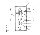
- FIG. 2 is a diagram showing a configuration of the light projecting / receiving unit 20 of FIG. 3 is a cross-sectional view taken along line III-III in FIG. 4 is a cross-sectional view taken along line IV-IV in FIG.
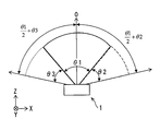
- FIG. 5 is a diagram illustrating the entire horizontal viewing angle of the optical distance measuring device according to the first embodiment.
- FIG. 6 is an enlarged view of the vicinity of the optical distance measuring device of FIG. FIG.
- FIG. 7 is a diagram illustrating the arrangement of the light projecting and receiving units in the optical distance measuring device according to the first modification.
- FIG. 8 is a diagram illustrating an overall configuration of the optical distance measuring device according to the second embodiment.
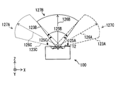
- FIG. 9 is a diagram illustrating the entire detection range of the optical distance measuring device according to the second embodiment.
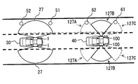
- FIG. 10 is a diagram comparing the detection ranges of the optical distance measuring device of the first embodiment and the optical distance measuring device of the second embodiment.
- FIG. 11 is a diagram illustrating an overall configuration of the optical distance measuring device according to the third embodiment.
- FIG. 12 is a diagram illustrating an overall configuration of the optical distance measuring device according to the fourth embodiment.
- FIG. 13 is a diagram illustrating the overall configuration of the optical distance measuring device according to the fifth embodiment.
- FIG. 14 is a diagram illustrating an overall configuration of the optical distance measuring device according to the sixth embodiment.
- FIG. 15 is a diagram illustrating an overall configuration of the optical distance measuring device according to the seventh embodiment.
- FIG. 16 is a diagram illustrating the horizontal viewing angle of the entire optical distance measuring device.
- FIG. 17 is an enlarged view of the vicinity of the optical distance measuring device of FIG.
- FIG. 18 is a diagram illustrating the overall configuration of the optical distance measuring device according to the eighth embodiment.
- 19 is a cross-sectional view taken along line XIX-XIX in FIG.
- FIG. 20 is a diagram illustrating the entire optical path of the light projecting / receiving unit.
- FIG. 21 is a diagram illustrating a configuration of a light projecting / receiving unit according to the ninth embodiment.
- FIG. 22 is a diagram illustrating an optical path of the optical distance measuring device according to the tenth embodiment.
- FIG. 23 is a diagram in which the optical distance measuring device is attached to the front end surface of the
- the optical distance measuring device 1 of 1st Embodiment is mounted in a vehicle, for example, and is arrange
- the z-axis direction is a direction perpendicular to the window 13.
- the y-axis direction is the vertical direction of the vehicle, and the x-axis direction is the front-rear direction of the vehicle.
- the optical distance measuring device 1 includes three light projecting / receiving units 20A, 20B, and 20C inside a housing 10.
- the housing 10 has a rectangular parallelepiped shape, and an opening surface 12 is formed in the front side wall portion 11 of the housing 10.
- the opening surface 12 is a plane representing an opening that penetrates the housing 10.
- the front side wall 11 of the housing 10 has a thickness.
- the position of the opening surface 12 in the thickness direction is the position of the outer surface of the front side wall portion 11 unless otherwise specified.
- the position of the opening surface 12 in the thickness direction of the front side wall portion 11 may be other positions within the thickness range of the front side wall portion 11.
- a window 13 that closes the opening surface 12 is attached to the opening surface 12.
- the window 13 is formed of a light transmissive member.
- the light projecting / receiving units 20A, 20B, and 20C of the present embodiment have the same configuration.
- the light projecting / receiving unit 20 corresponds to a light projecting / receiving unit.
- the light projecting / receiving unit 20 projects the projection light, which is a laser beam, and receives the reflected light generated by the reflection of the projection light by an external object.
- the light projecting / receiving unit 20 includes a light projecting unit 21 and a light receiving unit 22, which are accommodated in a unit housing 29.
- the arrangement direction of the light projecting unit 21 and the light receiving unit 22 is a vertical direction, which is a direction perpendicular to the light traveling direction.
- the light projecting unit 21 includes a light emitting element 211 and a light projecting lens 212.
- the light emitting element 211 is, for example, a laser diode, and projects projection light toward the light projecting lens 212.
- the light receiving unit 22 includes a light receiving lens 221 and a light receiving element 222.
- the light receiving lens 221 condenses the reflected light on the light receiving element 222.
- the light receiving element 222 is, for example, a photodiode.
- the light projecting lens 212 outputs the projection light emitted from the light emitting element 211 and incident on the light projecting lens 212 by deflecting it to an angle range of 50 degrees in the horizontal direction.
- the projection lens 212 has a lens array structure.
- the size of the light receiving element 222 of the light receiving unit 22 is 50 when the light projecting unit 21 projects the projection light in the range of 50 degrees in the horizontal direction. It has been adjusted to be degrees.
- Each of the light projecting / receiving units 20A, 20B, 20C has a horizontal viewing angle of 50 degrees. This 50 degree range becomes the optical paths 23A, 23B, and 23C through which the projection light and the reflected light pass.
- the three light projecting / receiving units 20A, 20B, 20C are arranged in the horizontal direction, that is, at the same height so that the vertical positions of the three optical paths 23A, 23B, 23C are the same. Yes.
- the posture of the optical distance measuring device 1 is determined so that the direction in which the three light projecting / receiving units 20A, 20B, and 20C are aligned is the horizontal direction.
- the three optical paths 23A, 23B, and 23C all pass through the opening surface 12, as shown in FIG. Further, the three optical paths 23A, 23B, and 23C overlap each other on the opening surface 12. Specifically, the optical path 23 ⁇ / b> A and the optical path 23 ⁇ / b> C are completely overlapped on the outer side surface 13 a of the window 13 attached to the opening surface 12. Further, the optical paths 23A and 23C include the entire optical path 23B on the opening surface 12, and are wider than the optical path 23B. Further, the optical axes 24A, 24B, 24C, which are the centers of the optical paths 23A, 23B, 23C, overlap at one point.
- the entire horizontal viewing angle of the optical distance measuring device 1 is as shown in FIG. ⁇ 1 + ⁇ 2 + ⁇ 3.
- ⁇ 2 is the horizontal viewing angle of the light projecting / receiving unit 20A
- ⁇ 3 is the horizontal viewing angle of the light projecting / receiving unit 20C.
- ⁇ 1 is an angle in a range that does not overlap with the horizontal viewing angle of the light projecting / receiving units 20A and 20C in the horizontal viewing angle of the light projecting / receiving unit 20B.
- the 0 degree direction is the front direction of the optical distance measuring device 1, and the optical axis 24B of the light projecting / receiving unit 20B is directed to the 0 degree direction.
- the entire horizontal viewing angle of the optical distance measuring device 1 is one light projecting and receiving unit.
- the viewing angle of the unit 20 is wider in the horizontal direction.
- the overall vertical viewing angle of the optical distance measuring device 1 is determined by each of the light projecting / receiving units 20A, 20B, It is the same as the vertical viewing angle of 20C.
- the entire field of view of the optical distance measuring device 1 is wider than the field of view of the single light projecting and receiving units 20A, 20B, and 20C. Is horizontal.
- the direction perpendicular to the direction in which the entire field of view of the optical distance measuring device 1 is wider than the field of view of one light projecting / receiving unit 20A, 20B, 20C is the vertical direction.
- FIG. 6 is an enlarged view of the vicinity of the optical distance measuring device 1 in FIG.
- the minimum horizontal length b of the side surface 13a can be expressed by Equation 1. This minimum length b is also the minimum opening size in the horizontal direction of the opening surface 12.
- the opening surface 12 is the minimum opening surface. Since the horizontal length of the opening surface 12 of this embodiment is longer than the minimum length b as shown in FIG. 6, the opening surface 12 is larger than the minimum opening surface.
- all the optical paths 23A, 23B, and 23C are within the range indicated by the minimum length b. That is, all the optical paths 23A, 23B, and 23C are within the minimum aperture plane.
- ⁇ 2 means the viewing angle of the light projecting / receiving unit having the largest horizontal length of the optical paths 23A, 23B, 23C on the aperture surface 12 among the three light projecting / receiving units 20A, 20B, 20C.
- ⁇ 3 is the same as ⁇ 2, and the calculation result is the same regardless of which of ⁇ 2 and ⁇ 3 is used. Therefore, in Equation 1, ⁇ 2 is used without using ⁇ 3. If ⁇ 3 is larger than ⁇ 2, ⁇ 3 is used instead of ⁇ 2.
- the minimum horizontal length b is a value represented by Equation 2.
- the virtual image light emission points 25A and 25C are points where lines at both ends of the visual field of the light projecting / receiving units 20A and 20C intersect, and the virtual image light emission points 25A and 25C are different from the actual light emission points.
- the relationship between the positions of the light emitting points of the light projecting / receiving units 20A and 20C and the positions of the virtual image light emitting points 25A and 25C can be known in advance. Therefore, the distance from the window 13 to the light projecting / receiving units 20A and 20C when the horizontal length of the outer side surface 13a of the window 13 is set to the minimum length b can be determined from Equation 1.
- the optical distance measuring device 1 Since the optical distance measuring device 1 according to the first embodiment is configured to include a plurality of light projecting / receiving units 20A, 20B, and 20C, the optical distance measuring device 1 is simpler than a type in which a distance measuring area is moved using a rotating mirror. The object can be detected over a wide angle range with the configuration.
- the opening surface 12 is compared with the case where the optical paths 23A, 23B, and 23C do not overlap with each other on the opening surface 12. Can be reduced.
- the optical axes 24A, 24B, and 24C overlap.
- the arrangement of the light projecting / receiving units 20A, 20B, and 20C in which the optical paths 23A, 23B, and 23C overlap on the opening surface 12 is the same as that of the first modification shown in FIG. , 24C does not overlap.
- the light projecting / receiving units 20A, 20B, and 20C are arranged so that the optical axes 24A, 24B, and 24C overlap as in the optical distance measuring device 1 according to the first embodiment,
- the overlap of the optical paths 23A, 23B, and 23C on the surface 12 can be increased. Therefore, the opening surface 12 can be further reduced.
- the first modification is also an arrangement of the light projecting and receiving units 20A, 20B, and 20C in which the optical paths 23A, 23B, and 23C overlap on the opening surface 12.
- the aperture surface 12 can be made smaller than when no optical path overlaps other optical paths on the aperture surface 12.
- the optical distance measuring device 100 includes three light projecting / receiving units 120A, 120B, and 120C as shown in FIG. These three light projecting / receiving units 120A, 120B, and 120C have the same configuration. When the three light projecting / receiving units 120A, 120B, and 120C are not distinguished, they are referred to as the light projecting / receiving unit 120.
- optical axes 124A, 124B, and 124C of these three light projecting / receiving units 120A, 120B, and 120C intersect at one place as in the first embodiment. Therefore, also in the second embodiment, the optical paths 123A, 123B, 123C of the light projecting / receiving units 120A, 120B, 120C overlap each other on the opening surface 12, as shown in FIG. In FIG. 9, the light projecting / receiving units 120A, 120B, and 120C are not shown.
- the difference between the light projecting / receiving unit 120A, 120B, 120C and the light projecting / receiving unit 20 of the first embodiment is the detection ranges 127A, 127B, 127C, that is, the detection distances 126A, 126B, 126C and the viewing angles 125A, 125B, 125C.
- the viewing angles 125A and 125C of the light projecting and receiving units 120A and 120C are the same angle, and these viewing angles 125A and 125C are narrower than the viewing angle 125B of the light projecting and receiving unit 120B.
- the light projecting / receiving units 120A, 120B, and 120C each include the light emitting element 211 provided in the light projecting / receiving unit 20 of the first embodiment.
- Each of the light projecting / receiving units 120A, 120B, and 120C has a viewing angle adjusted by a configuration of a light projecting lens that deflects the projection light projected by the light emitting element 211. Therefore, the light projecting / receiving units 120A and 120C having a relatively narrow viewing angle compared to the projecting / receiving unit 120B have a higher power density.
- each of the light projecting / receiving units 120A, 120B, and 120C includes the light receiving unit 22 provided in the light projecting / receiving unit 20 of the first embodiment. That is, the light receiving sensitivity of the light projecting / receiving units 120A, 120B, 120C is the same as the light projecting / receiving unit 20 of the first embodiment.
- the detection distances 126A and 126C of the light projecting / receiving units 120A and 120C are longer than the detection distance 126B of the light projecting / receiving unit 120B. Therefore, in the optical distance measuring device 100 of the second embodiment, the detection distance in the z-axis direction (that is, the front direction) at the end of the detection angle range of the entire device is longer than that of the optical distance measuring device 1 of the first embodiment. Become.
- the optical distance measuring device 100 having a long detection distance in the z-axis direction at the end of the detection angle range of the entire device, that is, the portion farthest from the front direction is suitable when mounted on the side surface of the vehicle.
- the optical distance measuring devices 1 and 100 are attached to the same positions on the side surfaces of the vehicles 30 and 40, and the side of the vehicles 30 and 40 is the front direction of the optical distance measuring devices 1 and 100.
- the object 51 and the object 61 have the same relative position with respect to the vehicles 30 and 40, and the object 52 and the object 62 also have the same relative position with respect to the vehicles 30 and 40.
- the optical distance measuring device 1 cannot detect the objects 51 and 52. .
- the detection ranges 127A and 127C of the optical distance measuring device 100 include the objects 61 and 62, the optical distance measuring device 100 can detect the objects 61 and 62.
- the detection ranges 127A, 127B, and 127C actually overlap each other partially as shown in FIG. 9, but in FIG. 10, these detection ranges 127A, 127B, and 127C are shown in a simplified manner.
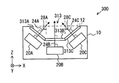
- the optical distance measuring devices 300, 400, 500, and 600 of the third, fourth, fifth, and sixth embodiments shown in FIGS. 11, 12, 13, and 14 include the same three projector / receiver units 20A, 20B and 20C are provided. These light projecting / receiving units 20A, 20B, and 20C are arranged in the housing 10 so that the optical axes 24A, 24B, and 24C are in the same positions as those in the first embodiment. Therefore, also in the third, fourth, fifth, and sixth embodiments, the light paths of the light projecting and receiving units 20A, 20B, and 20C overlap each other on the opening surface 12. Therefore, the optical distance measuring devices 300, 400, 500, and 600 of the third, fourth, fifth, and sixth embodiments have the same effects as the optical distance measuring device 1 of the first embodiment.
- the difference between the third, fourth, fifth, and sixth embodiments and the first embodiment is windows 313, 413, 513, and 613 attached to the opening surface 12 of the housing 10. These windows 313, 413, 513, 613 correspond to a light transmissive cover.
- the window 313 of the optical distance measuring device 300 has a shape protruding toward the inside of the housing 10 with respect to the opening surface 12, and includes end portions 313A and 313C, and a central portion 313B. It is the structure provided with.
- the end portions 313A, 313C and the central portion 313B are all flat plates.
- the end 313A is arranged perpendicular to the optical axis 24A of the light projecting / receiving unit 20A
- the end 313C is arranged perpendicular to the optical axis 24C of the light projecting / receiving unit 20C
- the central part 313B is projected / received.
- the unit 20B is disposed perpendicular to the optical axis 24B.
- the incident angle at which the optical axis 24B is incident on the window 313 is the same as the angle at which the optical axis 24B is incident on the opening surface 12. However, the incident angle (that is, 0 degree) at which the optical axis 24A is incident on the window 313 is smaller than the angle 28A at which the optical axis 24A is incident on the opening surface 12. The incident angle (that is, 0 degree) at which the optical axis 24C is incident on the window 313 is also smaller than the angle 28C at which the optical axis 24C is incident on the opening surface 12.
- the window 313 is recessed in the interior direction of the housing 10 from the opening surface 12, the size in the depth direction of the center portion of the apparatus can be reduced. There is also an advantage that the window 313 is not easily damaged.
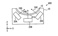
- the window 413 of the optical distance measuring device 400 of the fourth embodiment shown in FIG. 12 has a shape in which the inner surface and the outer surface of the window 413 are convex curved surfaces that protrude toward the inside of the housing 10.
- the vertex of the convex curved surface is at the center in the left-right direction, and the optical axis 24B of the light projecting / receiving unit 20B passes through this vertex.
- the angle at which the projection light enters the window 413 is smaller than that in the first embodiment in the entire range except the direction of the optical axis 24B. Therefore, the occurrence of Fresnel reflection when the projection light enters the window 413 can be suppressed.
- the Fresnel reflection is suppressed by the shape of the window 413, the Fresnel reflection can be suppressed even at a high temperature as in the third embodiment. Further, since the window 413 is recessed inward of the housing 10 relative to the opening surface 12, the size in the depth direction of the center of the apparatus can be reduced, and the window 413 is not easily damaged.
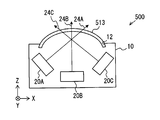
- the window 513 of the optical distance measuring device 500 of the fifth embodiment shown in FIG. 13 has a shape in which the inner surface and the outer surface of the window 513 are convex curved surfaces protruding outside the housing 10, contrary to the fourth embodiment. Also in this window 513, the vertex of the convex curved surface is at the center in the left-right direction, and the optical axis 24B of the light projecting / receiving unit 20B passes through this vertex.
- the angle at which the projection light enters the window 513 is smaller than that in the first embodiment in the entire range except the direction of the optical axis 24B. Therefore, it is possible to suppress the occurrence of Fresnel reflection when the projection light enters the window 513. Also in the fifth embodiment, since the Fresnel reflection is suppressed by the shape of the window 513, the Fresnel reflection can be suppressed even at a high temperature.
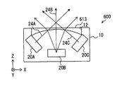
- the window 613 of the optical distance measuring device 600 is a concave lens having a concave shape on the inside. Since the window 613 has a concave lens shape, the projection light projected by the light projecting / receiving unit 20 is deflected to a wide angle when passing through the window 613. Therefore, even when the entire viewing angle of the optical distance measuring device 600 is the same as that of the optical distance measuring device 1 of the first embodiment, the projection angle range of the projection light projected by the light projecting / receiving unit 20 and the light reception for receiving the reflected light. The angle range can be made smaller than in the first embodiment.
- the light projecting unit 21 When the projection light is deflected at a wide angle in the light projecting unit 21, it is necessary to increase the number of lenses or a lens shape having a high manufacturing difficulty. Therefore, the light projecting unit 21 has a narrower deflection angle. The manufacturing cost can be reduced. Also, when the light receiving unit 22 receives light at a wide angle, it is necessary to increase the number of lenses or to form a lens shape that is highly difficult to manufacture. Therefore, the manufacturing cost can be reduced by using the concave lens type window 613 as in the sixth embodiment.
- Each of the optical distance measuring devices 1, 100, 300, 400, 500, and 600 described so far includes three light projecting and receiving units 20 and 120.
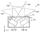
- the optical distance measuring device 700 according to the seventh embodiment includes two light projecting / receiving units 720A and 720B inside a housing 710 as shown in FIG.
- the optical distance measuring device 700 is mounted on a vehicle, for example, and is arranged so that the z-axis direction shown in FIG. 15 is directed to the side of the vehicle.
- the housing 710 has a rectangular parallelepiped shape, and an opening surface 712 is formed in the front side wall portion 711 of the housing 710.
- a window 713 formed of a light transmissive member is attached to the opening surface 712.
- the two light projecting / receiving units 720A and 720B have the same configuration, and will be referred to as a light projecting / receiving unit 720 when they are not distinguished from each other.
- the light projecting / receiving unit 720 corresponds to a light projecting / receiving unit.
- the light projecting / receiving unit 720 includes a light projecting unit and a light receiving unit, similar to the light projecting / receiving unit 20 of the first embodiment.
- the basic configurations of the light projecting unit and the light receiving unit included in the light projecting / receiving unit 720 are the same as those of the light projecting unit 21 and the light receiving unit 22 of the first embodiment.
- the difference between the light projecting / receiving unit 720 and the light projecting / receiving unit 20 of the first embodiment is the viewing angle.
- the light projecting / receiving unit 720 of the seventh embodiment has a wider viewing angle than that of the light projecting / receiving unit 20 of the first embodiment.
- the viewing angle of the light projecting / receiving unit 720 is 62.5 degrees.
- the light projecting / receiving unit 720 is adjusted in the deflection angle of the light projecting lens, the size of the light receiving lens, and the like.
- the optical path 723A of the light projecting / receiving unit 720A and the optical path 723B of the light projecting / receiving unit 720B both pass through the opening surface 712, and the two optical paths 723A, 723B are the opening surface. At 712, they completely overlap each other. That is, the positions at which the two optical paths 723A and 723B pass through the opening surface 712 coincide with each other. Further, the optical axes 724A and 724B, which are the centers of the two optical paths 723A and 723B, overlap at one point.
- the viewing angle in the horizontal direction of the entire optical distance measuring device 700 is ⁇ 4 + ⁇ 5 as shown in FIG. ⁇ 4 is the viewing angle of the light projecting / receiving unit 720A, and ⁇ 5 is the viewing angle of the light projecting / receiving unit 720B. If ⁇ 4 and ⁇ 5 are each 62.5 degrees, the entire horizontal viewing angle of the optical distance measuring device 700 is 125 degrees.
- Equation 3 is the case of ⁇ 4 ⁇ ⁇ 5.
- the optical distance measuring device 800 of the eighth embodiment includes the same two light projecting / receiving units 720A and 720B as in the seventh embodiment. These two light projecting / receiving units 720A and 720B are accommodated in a housing 810.
- the housing 810 is the same as the housing 710 of the seventh embodiment in that it has a rectangular parallelepiped shape. However, the casing 810 has a space in the vertical direction so that the two light projecting / receiving units 720A and 720B can be arranged at different vertical positions.
- the two light projecting / receiving units 720A and 720B partially overlap when viewed from the Y-axis direction, that is, viewed from the vertical direction.
- the reason why such an arrangement is possible is that the two light projecting / receiving units 720A and 720B are arranged so that their vertical positions do not overlap each other, as shown in FIG.
- the entire horizontal viewing angle of the optical distance measuring device 800 is larger than the viewing angle of one light projecting / receiving unit 720A and 720B. Wide in the horizontal direction.
- the overall horizontal viewing angle of the optical distance measuring device 800 is 125 degrees, as in the seventh embodiment.
- the direction in which the entire viewing angle of the optical distance measuring device 800 is wider than the viewing angle of one light projecting / receiving unit 720A, 720B is the horizontal direction.
- FIG. 20 is a diagram showing the entire optical paths 723A and 723B of the light projecting and receiving units 720A and 720B in the optical distance measuring device 800.
- the vertical directions of the two optical paths 723A and 723B are almost the same. It can be regarded as overlapping. Therefore, in the eighth embodiment, the vertical direction is not a direction in which the viewing angle of the entire apparatus is wider than the viewing angle of one light projecting / receiving unit 720A, 720B.
- both of the optical paths 723A and 723B are the optical distance measuring device 800. It is a shape in which the width in the Y-axis direction becomes wider as the distance from the center increases. In the case of this shape, the two optical paths 723A and 723B can be regarded as substantially overlapping. Also from this, the vertical direction is not a direction in which the viewing angle of the entire apparatus is wider than the viewing angle of one light projecting / receiving unit 720A, 720B.
- the positions of the light projecting / receiving units 720A and 720B in the Y-axis direction are different from each other, so that the two optical paths 723A and 723B do not overlap on the opening surface 812.
- the two optical paths 723A and 723B when the two optical paths 723A and 723B are viewed from the Y-axis direction, the two optical paths 723A and 723B overlap at the position of the opening surface 812. Further, when viewed from the Y-axis direction, the optical axes 724A and 724B also overlap at one point.
- the two optical paths 723A and 723B are combined, so that the entire horizontal viewing angle of the optical distance measuring device 800 is the viewing angle of one light projecting and receiving unit 720A and 720B.
- the two optical paths 723A and 723B overlap at the position of the opening surface 812. Therefore, also in this embodiment, the length of the opening surface 812 in the X-axis direction is shorter than that in the case where the two optical paths 723A and 723B do not overlap at the position of the opening surface 812 when viewed from the Y-axis direction. ing.
- FIG. 21 shows an optical distance measuring device 900 according to the ninth embodiment.
- the optical distance measuring device 900 includes a light projecting / receiving unit 920 instead of the light projecting / receiving unit 20 of the first embodiment. Therefore, it corresponds to the light projecting / receiving unit of the light projecting / receiving unit 920.
- the optical distance measuring device 900 includes three light projecting / receiving units 920, and each of the three light projecting / receiving units 920 includes three light projecting / receiving units. Arranged at the positions of the units 20A, 20B, and 20C. These three light projecting / receiving units 920 are arranged in the housing 10. Since the housing 10 is the same as in the first embodiment, an opening surface 12 is formed in the front side wall portion 11, and a window 13 is attached to the opening surface 12.
- the light projecting / receiving unit 920 includes two light projecting units 921, an upper light projecting unit 921 ⁇ / b> A and a lower light projecting unit 921 ⁇ / b> B, and one light receiving unit 922. These are housed in one unit housing 929.
- the upper side light projecting unit 921A, the lower side light projecting unit 921B, and the light receiving unit 922 are arranged in this order in order from the upper direction in the Y axis direction along with the Y axis direction.
- Both the upper light projecting unit 921A and the lower light projecting unit 921B include a light emitting element 9211 and a light projecting lens 9212. Each of the two light emitting elements 9211 projects the projection light toward the light projecting lens 9212. Each of the two light projecting lenses 9212 deflects and outputs the projection light. Further, the two light projecting lenses 9212 are both arranged so that the optical axis is in the horizontal direction.
- the relative position of the light emitting element 9211 with respect to the light projecting lens 9212 is different between the upper light projecting unit 921A and the lower light projecting unit 921B.
- the portion of the light emitting element 9211 where the projection light is output is located above the optical axis of the light projecting lens 9212. Accordingly, the viewing angle 925A of the upper light projecting portion 921A is formed below the optical axis of the light projecting lens 9212.
- the viewing angle 925 ⁇ / b> B of the lower light projecting unit 921 ⁇ / b> B is formed above the optical axis of the light projecting lens 9212.
- the viewing angle 925A of the upper light projecting unit 921A and the viewing angle 925B of the lower light projecting unit 921B mean an angle at which the optical path of the projection light spreads as shown in FIG.
- the optical path 923A of the upper light projecting unit 921A and the optical path 923B of the lower light projecting unit 921B are completely overlapped in the vertical direction on the opening surface 12.
- the light receiving unit 922 includes a light receiving lens 9221, a light receiving element, and 9222.
- the light receiving lens 9221 condenses the light reflected by the projection light projected by the upper light projecting unit 921A and the light reflected by the projection light projected by the lower light projecting unit 921B on the light receiving element 9222.
- the light receiving element 9222 detects the reflected light collected by the light receiving lens 9221.
- the light projecting / receiving unit 920 of the ninth embodiment includes two light projecting units 921A and 921B. Therefore, it is possible to widen the vertical visual field while maintaining the same detection distance as when only one light projecting unit 921 is provided, or to increase the number of vertical azimuths.
- the optical path 923A of the upper light projecting portion 921A and the optical path 923B of the lower light projecting portion 921B are completely overlapped in the vertical direction on the opening surface 12.
- the vertical size of the opening surface 12 can be reduced as compared with the case where the vertical positions of the optical paths 923A and 923B do not overlap with each other on the opening surface 12.
- the horizontal viewing angle of the light projecting / receiving unit 920 is not particularly limited. Therefore, the horizontal viewing angle of the light projecting / receiving unit 920 is made the same as that of any of the light projecting / receiving units 20, 120, 720 shown in the previous embodiments, and this light projecting / receiving unit 920 is made to be the light projecting / receiving unit 20, 120, It can be used instead of 720.
- FIG. 22 shows an optical distance measuring apparatus 1000 according to the tenth embodiment.
- the optical distance measuring device 1000 of the tenth embodiment is a device in which the viewing angles of the three light projecting / receiving units 20A, 20B, and 20C included in the optical distance measuring device 1 of the first embodiment are changed. Since only the viewing angles of the three light projecting / receiving units 20 are changed from the first embodiment, the detailed configuration is not shown, and the same reference numerals as those in the first embodiment are used for convenience.
- the three light projecting / receiving units 20A, 20B, and 20C included in the optical distance measuring device 1000 form optical paths 1023A, 1023B, and 1023C shown in FIG.
- the optical distance measuring device 1000 only changes the viewing angles of the three light projecting / receiving units 20 from the first embodiment. Therefore, these optical paths 1023A, 1023B, and 1023C overlap each other on the opening surface 12, and the optical axes of these optical paths 1023A, 1023B, and 1023C overlap at one point.
- the first embodiment it is the same as the second embodiment in that only the viewing angles of the three light projecting / receiving units 20 are changed.
- the difference from the second embodiment is that in the second embodiment, of the three optical paths 123A, 123B, and 123C, the optical paths 123A and 123C that go to the end of the detection angle range of the entire apparatus are the front of the detection angle range of the entire apparatus. It was narrower than the optical path 123B in the direction.
- the optical path 1023B toward the front of the detection angle range of the entire apparatus is narrower than the optical paths 1023A and 1023C toward the end of the detection angle range of the entire apparatus. It has become.
- ⁇ 7 is the horizontal viewing angle of the light projecting / receiving unit 20A
- ⁇ 8 is the horizontal viewing angle of the light projecting / receiving unit 20C
- ⁇ 6 is an angle in a range that does not overlap with the horizontal viewing angles of the light projecting / receiving units 20A and 20C among the horizontal viewing angles of the light projecting / receiving unit 20B.
- the detection distance of the detection range 1027B which is the front direction of the detection angle range of the entire apparatus, is opposite to that of the second embodiment. It is longer than the detection distances of the detection ranges 1027A and 1027C, which are the ends of the detection angle range, that is, the portions farthest from the front direction.
- the detection ranges 1027A, 1027B, and 1027C are detection ranges of the light projecting / receiving units 20A, 20B, and 20C, respectively.
- the optical distance measuring device 1000 As shown in FIG. 23, the optical distance measuring device 1000 according to the tenth embodiment is attached to the front end surface of the vehicle 40 and forms a detection range in front of the traveling direction of the vehicle 40. When this optical distance measuring device 1000 is attached to the front end surface of the vehicle, the detection distance in the front direction of the vehicle 40 can be made longer than the detection distance obliquely forward of the vehicle 40.
- ⁇ Modification 2> In the above-described embodiment, two or three light projecting / receiving units 20, 120, 720, 920 are provided. However, the number of light projecting / receiving units 20, 120, 720, 920 may be four or more.
- the window 613 of the sixth embodiment has a concave shape on the inner surface, but may have a concave lens shape on the opposite side, which is a concave surface.
- the light paths 23A, 23B, and 23C of the light projecting and receiving units 20A, 20B, and 20C do not need to overlap each other on the opening surface 12. Therefore, for example, in the fifth embodiment, the positions of the light projecting / receiving units 20A and 20C may be interchanged.
- light projecting / receiving units 20A, 20B, 20C instead of the light projecting / receiving units 20A, 20B, 20C, light projecting / receiving units 120A, 120B, 120C may be used.
- the light projecting / receiving units 120A, 120B, 120C instead of the light projecting / receiving units 120A, 120B, 120C, the light projecting / receiving units 20A, 20B, 20C are used, and the light emitting power of the light emitting element 211 of the light projecting / receiving unit 20B is set to the light emission of the light projecting / receiving units 20A, 20C. It may be lower than the element 211.
- the light projecting / receiving unit having the viewing distance of the light emitting / receiving unit 20A, 20C whose viewing angle is the end of the entire detection angle range of the optical distance measuring device is the viewing angle of the front direction of the optical ranging device. It can be longer than 20B.
- the optical distance measuring device 1000 of the tenth embodiment may be attached to the rear end surface of the vehicle 40.
- the light emitting element 9211 is shifted upward or downward from the optical axis of the light projecting lens 9212.
- the light emitting element 9211 may be disposed on the optical axis of the light projecting lens 9212, and the light emitting element 9211 and the light projecting lens 9212 may be rotated in the vertical direction within the vertical plane. Even in this case, the visual field in the vertical direction can be expanded or the number of vertical azimuths can be increased.
- the light projecting / receiving unit 120C may be omitted.
- the detection range 127A that goes to the rear side of the vehicle 40 is eliminated.
- the light projecting / receiving unit 120C is omitted.
- the light projecting / receiving unit 120A is a light projecting / receiving unit having a viewing angle in a direction farthest from the front direction in the entire detection angle range of the optical distance measuring device 100.
- This light projecting / receiving unit 120A has a longer detection distance than the light projecting / receiving unit 120B whose viewing angle is the front direction of the optical distance measuring device 100.
- the detection range 127C directed to the front side of the vehicle 40 is unnecessary.
- the light projecting / receiving unit 120A is omitted.
- either one of the light projecting / receiving units 20A and 20C may be omitted.
- any of the detection ranges 1027A and 1027C disappears.
- the light projecting / receiving unit 20C projects the direction farthest from the front direction in the entire detection angle range of the optical distance measuring device 1000. Becomes a light receiving unit.
- the light projecting / receiving unit 20B whose viewing angle is the front direction of the optical distance measuring device 1000 has a longer detection distance and a smaller viewing angle than the light projecting / receiving unit 20C.
Landscapes
- Engineering & Computer Science (AREA)
- Physics & Mathematics (AREA)
- Computer Networks & Wireless Communication (AREA)
- General Physics & Mathematics (AREA)
- Radar, Positioning & Navigation (AREA)
- Remote Sensing (AREA)
- Electromagnetism (AREA)
- Mechanical Engineering (AREA)
- Optical Radar Systems And Details Thereof (AREA)
- Measurement Of Optical Distance (AREA)
Abstract
光測距装置を提供する。光測距装置(1)は、開口面(12)を備えた筐体(10)と、前記筐体(10)に収容され、レーザ光である投射光を投光するとともに反射光を受光する複数の投受光部(20)とを備える。複数の前記投受光部(20)の各光路(23)が組み合わせられることにより1つの前記投受光部(20)の視野角よりも装置全体の視野角が広がっている方向に対して垂直な方向から見た場合に、複数の前記投受光部(20)の光路(23)が前記開口面(12)の位置において互いに重なるように、複数の前記投受光部(20)は前記筐体(10)内に配置されている。
Description
本出願は、2016年1月22日に出願された日本特許出願番号2016-11109号および2016年11月14日に出願された日本特許出願番号2016-221886に基づくもので、それらの開示をここに参照により援用する。
本開示は、光測距装置に関し、特に、広い角度範囲に渡り対象物を検出できる光測距装置に関する。
広い角度範囲に渡り対象物を検出できる光測距装置として、たとえば特許文献1に記載の距離測定装置が知られている。特許文献1に開示されている距離測定装置は、複数のレーザ投受光手段を仮想平面に沿って放射状に並べて配置している。この構成によれば、回転ミラーを用いて測距領域を移動させるタイプに比較して簡易な構成としつつ、広い角度範囲に渡り対象物を検出できる。
特許文献1の距離測定装置では、広い角度範囲に渡り対象物を検出できるようにするため、複数のレーザ投受光手段の光路が互いに重ならないように、それらレーザ投受光手段を配置している。
レーザ投受光手段の光路が筐体を通過する部分は、光が通過できるよう、開口とする必要がある。特許文献1の装置では、複数のレーザ投受光手段の光路が互いに重ならないようにしているので、この開口を大きくしなければならないという問題があった。より詳しくは、特許文献1の装置では、複数の光路は、互いに重ならないようにして水平方向に並んでいるので、開口を水平方向に大きくしなければならない。
開口が大きいと、光測距装置を、たとえば車両など、光測距装置を使用する処理を行う機器に取り付けた場合、その機器には、開口よりも大きい光透過性のカバーが必要になってしまう。光透過性のカバーを取り付けずに光測距装置の開口を露出させるとしても、開口よりも大きい貫通穴を、光測距装置を取り付ける機器に設ける必要がある。
開口が大きいとは、具体的には、開口が横方向に大きい、開口が縦方向に大きい、開口が横方向にも縦方向にも大きいの3つのいずれかを意味する。よって、開口面が小さいとは、開口面が横方向に小さい、開口面が縦方向に小さい、開口面が横方向にも縦方向にも小さいの3つのいずれかを意味する。なお、ここでの横方向は任意の直線方向であり、たとえば、水平方向である。縦方向は、横方向に垂直な方向であり、横方向が水平方向である場合、縦方向は鉛直方向である。
開口面が水平方向に大きいと、光測距装置を取り付ける機器が備えるカバーの水平方向サイズが大きくなってしまい、開口面が鉛直方向に大きいと、そのカバーの鉛直方向サイズが大きくなってしまう。開口面が水平方向にも鉛直方向にも大きいと、カバーの水平方向サイズおよび鉛直方向サイズがともに大きくなってしまうことになる。
また、広い角度範囲に渡り対象物を検出できるようにする場合、広い角度範囲に渡りレーザ光を投受光することになるので、光測距装置の開口に取り付けられた光透過性カバーにレーザ光が浅い角度で入射する恐れがある。
光透過性カバーに対してレーザ光が浅い角度で入射すると、大きなフレネル反射が生じる可能性が高くなる。フレネル反射を抑制する方法としてはARコートを付けることが一般的である。しかし、ARコートは耐熱性に課題がある。光測距装置がARコートの耐熱性を超えた温度で使用されて、ARコートが機能しなくなれば、フレネル反射が抑制されにくくなる。
この事情に基づいて、本開示の第1の目的は、簡易な構成で広い角度範囲に渡り対象物を検出でき、開口面を小さくすることができる光測距装置を提供することにある。また、第2の目的は、簡易な構成で広い角度範囲に渡り対象物を検出でき、高い温度でもフレネル反射をよく抑制できる光測距装置を提供することにある。
上記目的を達成するための第1の側面の光測距装置は、開口面を備えた筐体と、筐体に収容され、レーザ光である投射光を投光するとともに反射光を受光する複数の投受光部とを備えた光測距装置であって、複数の投受光部の各光路が組み合わせられることにより1つの投受光部の視野角よりも装置全体の視野角が広がっている方向に対して垂直な方向から見た場合に、複数の投受光部の光路が開口面の位置において互いに重なるように、複数の投受光部は筐体内に配置されている。
この第1の側面の光測距装置によれば、複数の投受光部を備える構成であるので、簡易な構成で広い角度範囲に渡り、対象物を検出することができる。また、1つの投受光部の視野角よりも装置全体の視野角が広がっている方向に対して垂直な方向から見た場合に、複数の投受光部の光路が開口面の位置において互いに重なる。よって、1つの投受光部の視野角よりも装置全体の視野角が広がっている方向に対して垂直な方向から見た場合にも複数の投受光部の光路が開口面において重ならない場合に比較して、装置全体の視野角が広がっている方向における開口面のサイズを小さくすることができる。
また、第2の側面の光測距装置は、開口面を備えた筐体と、筐体に収容され、レーザ光である投射光を投光するとともに反射光を受光する複数の投受光部と、開口面に取り付けられた光透過性カバーとを備え、複数の投受光部の光軸がそれぞれ光透過性カバーに入射する角度である複数の入射角のうち少なくとも一つは、当該入射角を算出したものと同じ光軸と開口面との角度よりも小さく、かつ、複数の入射角は、いずれも、当該入射角を算出したものと同じ光軸と開口面との角度以下である。
この第2の側面の光測距装置によれば、複数の投受光部を備える構成であるので、簡易な構成で広い角度範囲に渡り、対象物を検出することができる。また、光透過性カバーを、開口面を塞ぐ平面とした場合よりも、投射光が光透過性カバーに入射する角度が小さくなる。よって、光透過性カバーを、開口面を塞ぐ平面とした場合よりも、フレネル反射を抑制することができる。また、光透過性カバーの形状によってフレネル反射を抑制するので、高い温度でもフレネル反射を抑制できる。
本開示についての上記および他の目的、特徴や利点は、添付図面を参照した下記の詳細な説明から、より明確になる。図面において、
図1は、第1実施形態の光測距装置1の全体構成を示す図である。
図2は、図1の投受光ユニット20の構成を示す図である。
図3は、図2のIII-III線断面図である。
図4は、図2のIV-IV線断面図である。
図5は、第1実施形態の光測距装置の全体の水平方向の視野角を示す図である。
図6は、図5の光測距装置の付近を拡大した図である。
図7は、変形例1の光測距装置における投受光ユニットの配置を示す図である。
図8は、第2実施形態の光測距装置の全体構成を示す図である。
図9は、第2実施形態の光測距装置の全体の検知範囲を示す図である。
図10は、第1実施形態の光測距装置と第2実施形態の光測距装置の検知範囲を比較して示す図である。
図11は、第3実施形態の光測距装置の全体構成を示す図である。
図12は、第4実施形態の光測距装置の全体構成を示す図である。
図13は、第5実施形態の光測距装置の全体構成を示す図である。
図14は、第6実施形態の光測距装置の全体構成を示す図である。
図15は、第7実施形態の光測距装置の全体構成を示す図である。
図16は、光測距装置の全体の水平方向の視野角を示す図である。
図17は、図16の光測距装置付近を拡大した図である。
図18は、第8実施形態の光測距装置の全体構成を示す図である。
図19は、図18のXIX-XIX線断面図である。
図20は、投受光ユニットの全体の光路を示す図である。
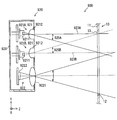
図21は、第9実施形態の投受光ユニットの構成を示す図である。
図22は、第10実施形態の光測距装置の光路を示す図である。
図23は、光測距装置が車両の前端面に取り付けられた図である。
<第1実施形態>
以下、実施形態を図面に基づいて説明する。第1実施形態の光測距装置1は、たとえば、車両に搭載されて、図1に示すz軸方向が車両の側方に向かうように配置される。z軸方向は、窓13に対して垂直な方向である。また、y軸方向は車両の上下方向であり、x軸方向は車両の前後方向である。
以下、実施形態を図面に基づいて説明する。第1実施形態の光測距装置1は、たとえば、車両に搭載されて、図1に示すz軸方向が車両の側方に向かうように配置される。z軸方向は、窓13に対して垂直な方向である。また、y軸方向は車両の上下方向であり、x軸方向は車両の前後方向である。
この光測距装置1は、図1に示すように、筐体10の内部に3つの投受光ユニット20A、20B、20Cを備える。筐体10は直方体形状であり、筐体10の前側壁部11には、開口面12が形成されている。開口面12は筐体10を貫通する開口を表す平面である。なお、筐体10の前側壁部11には厚さがある。この厚さ方向における開口面12の位置は、特に言及しない場合、前側壁部11の外側面の位置とする。ただし、前側壁部11の厚さ方向における開口面12の位置を、前側壁部11の厚さの範囲内で、その他の位置としてもよい。前側壁部11の厚さの範囲内で、前側壁部11の厚さ方向に開口面12の位置を変化させても、開口面12の面積に変化はないからである。この開口面12には、その開口面12を塞ぐ窓13が取り付けられている。窓13は光透過性部材で形成されている。
本実施形態の投受光ユニット20A、20B、20Cは互いに同じ構成である。以下、これらの3つの投受光ユニット20A、20B、20Cを区別しない場合には、投受光ユニット20と記載する。投受光ユニット20は投受光部に相当する。
投受光ユニット20は、レーザ光である投射光を投光し、投射光が外部の物体で反射されて生じた反射光を受光する。
[投受光ユニット20の構成]
図2に示すように、投受光ユニット20は、投光部21と、受光部22とを備えており、これらはユニット筐体29に収容されている。これら投光部21と受光部22の配列方向は、上下方向であり、光の進行方向と垂直の方向になっている。
図2に示すように、投受光ユニット20は、投光部21と、受光部22とを備えており、これらはユニット筐体29に収容されている。これら投光部21と受光部22の配列方向は、上下方向であり、光の進行方向と垂直の方向になっている。
投光部21は、発光素子211と投光レンズ212を備える。発光素子211は、たとえばレーザダイオードであり投射光を投光レンズ212に向けて投光する。受光部22は、受光レンズ221と受光素子222を備える。受光レンズ221は、反射光を受光素子222に集光する。受光素子222は、たとえばフォトダイオードである。
図3に示すように、投光レンズ212は、発光素子211が発光して投光レンズ212に入射された投射光を、水平方向に50度の角度範囲に偏向して出力する。この投光レンズ212はレンズアレイ構造を有する。
投光部21が、水平方向に50度の範囲で投射光を投光することに合わせ、図4に示すように、受光部22の受光素子222の大きさは、水平方向の視野角が50度になるように調整されている。
[投受光ユニット20の配置]
説明を図1に戻す。各投受光ユニット20A、20B、20Cの水平方向の視野角は、いずれも50度である。この50度の範囲が投射光および反射光が通過する光路23A、23B、23Cとなる。
説明を図1に戻す。各投受光ユニット20A、20B、20Cの水平方向の視野角は、いずれも50度である。この50度の範囲が投射光および反射光が通過する光路23A、23B、23Cとなる。
これら3つの光路23A、23B、23Cの鉛直方向の位置が互いに同じになるように、3つの投受光ユニット20A、20B、20Cは、水平方向に並んで、すなわち、互いに同じ高さに配置されている。換言すれば、3つの投受光ユニット20A、20B、20Cが並んでいる方向が水平方向になるように、光測距装置1は姿勢が決定される。
さらに、3つの光路23A、23B、23Cは、図1に示すように、いずれも、開口面12を通過している。また、3つの光路23A、23B、23Cは、開口面12において互いに重なっている。詳しくは、光路23Aと光路23Cは、開口面12に取り付けられた窓13の外側面13aにおいて、完全に重なっている。また、光路23A、23Cは、開口面12においては光路23Bを全部含み、光路23Bよりも広くなっている。さらに、光路23A、23B、23Cのそれぞれの中心となる光軸24A、24B、24Cは、一点において重なっている。
光路23A、23B、23Cがこのようになるように投受光ユニット20A、20B、20Cが配置されている場合、図5に示すように、光測距装置1の全体の水平方向の視野角は、θ1+θ2+θ3になる。なお、θ2は、投受光ユニット20Aの水平方向の視野角であり、θ3は、投受光ユニット20Cの水平方向の視野角である。また、θ1は、投受光ユニット20Bの水平方向の視野角のうち、投受光ユニット20A、20Cの水平方向の視野角と重複していない範囲の角度である。0度方向は光測距装置1の正面方向であり、投受光ユニット20Bの光軸24Bは0度方向に向いている。
図5から分かるように、3つの投受光ユニット20A、20B、20Cの光路23A、23B、23Cが組みわせられることにより、光測距装置1の全体の水平方向の視野角は、1つの投受光ユニット20の視野角よりも、水平方向に広くなっている。
一方、前述したように、3つの光路23A、23B、23Cの鉛直方向の位置は互いに同じであるので、光測距装置1の全体の鉛直方向の視野角は、各投受光ユニット20A、20B、20Cの鉛直方向の視野角と同じである。
よって、水平方向および鉛直方向のうち、光路23A、23B、23Cが組み合わせられることにより、1つの投受光ユニット20A、20B、20Cの視野よりも光測距装置1の全体の視野が広がっている方向は水平方向である。また、1つの投受光ユニット20A、20B、20Cの視野よりも光測距装置1の全体の視野が広がっている方向に対して垂直な方向は鉛直方向である。
図6は、図5における光測距装置1の付近を拡大した図である。図6から分かるように、光路23A、23Cが窓13の外側面13aで重なっている場合、窓13の外側面13aから虚像発光点25A、25Cまでの距離をaとしたとき、窓13の外側面13aの水平方向の最小長さbは式1で表すことができる。この最小長さbは、開口面12の水平方向の最小開口サイズでもある。開口面12の水平方向長さがこの最小長さbになっている場合、開口面12は最小開口面となる。本実施形態の開口面12の水平方向長さは、図6に示すように、最小長さbよりも長いので、開口面12は最小開口面よりも大きくなっている。ただし、すべての光路23A、23B、23Cが最小長さbで示される範囲に収まっている。つまり、すべての光路23A、23B、23Cが最小開口面内に収まっている。
なお、θ2は、3つの投受光ユニット20A、20B、20Cのうち、開口面12における光路23A、23B、23Cの水平方向の長さが最も大きい投受光ユニットの視野角を意味する。θ3もθ2と同じであり、θ2およびθ3のいずれを用いても計算結果が同じになるので、式1ではθ3を用いずθ2を用いている。θ2よりもθ3の方が大きい場合には、θ2に代えてθ3を用いる。


[第1実施形態のまとめ]
この第1実施形態の光測距装置1は、複数の投受光ユニット20A、20B、20Cを備える構成であることから、回転ミラーを用いて測距領域を移動させるタイプに比較して、簡易な構成で広い角度範囲に渡り、対象物を検出することができる。
この第1実施形態の光測距装置1は、複数の投受光ユニット20A、20B、20Cを備える構成であることから、回転ミラーを用いて測距領域を移動させるタイプに比較して、簡易な構成で広い角度範囲に渡り、対象物を検出することができる。
また、複数の投受光ユニット20A、20B、20Cの光路23A、23B、23Cが開口面12において互いに重なるので、光路23A、23B、23Cが開口面12において重ならない場合に比較して、開口面12を小さくすることができる。
また、第1実施形態の光測距装置1は、光路23A、23B、23Cが開口面12において重なることに加えて、光軸24A、24B、24Cが重なっている。この第1実施形態とは異なり、光路23A、23B、23Cが開口面12において重なる投受光ユニット20A、20B、20Cの配置としては、図7に示す変形例1のように、光軸24A、24B、24Cが重ならない配置もある。この変形例1の配置に比較して、第1実施形態の光測距装置1のように、光軸24A、24B、24Cが重なるように投受光ユニット20A、20B、20Cを配置する場合、開口面12における光路23A、23B、23Cの重なりを多くすることができる。よって、より開口面12を小さくすることができる。
なお、変形例1も、光路23A、23B、23Cが開口面12において重なる投受光ユニット20A、20B、20Cの配置である。このことから分かるように、3つ以上の光路がある場合に、開口面12において1つの光路が残りの光路の全部と重なる必要はない。開口面12において少なくとも2つの光路が互いに重なっていれば、開口面12においていずれの光路も他の光路と重なっていない場合に比較して、開口面12を小さくできる。
<第2実施形態>
次に、第2実施形態を説明する。この第2実施形態以下の説明において、それまでに使用した符号と同一番号の符号を有する要素は、特に言及する場合を除き、それ以前の実施形態における同一符号の要素と同一である。また、構成の一部のみを説明している場合、構成の他の部分については先に説明した実施形態を適用できる。
次に、第2実施形態を説明する。この第2実施形態以下の説明において、それまでに使用した符号と同一番号の符号を有する要素は、特に言及する場合を除き、それ以前の実施形態における同一符号の要素と同一である。また、構成の一部のみを説明している場合、構成の他の部分については先に説明した実施形態を適用できる。
第2実施形態の光測距装置100は、図8に示すように、3つの投受光ユニット120A、120B、120Cを備える。これらの3つの投受光ユニット120A、120B、120Cは互いに同じ構成である。これら3つの投受光ユニット120A、120B、120Cを区別しないときは、投受光ユニット120と記載する。
これら3つの投受光ユニット120A、120B、120Cの光軸124A、124B、124Cは、第1実施形態と同様、1箇所で交わっている。したがって、第2実施形態においても、投受光ユニット120A、120B、120Cの光路123A、123B、123Cは、図9に示すように、開口面12において互いに重なっている。なお、図9では、投受光ユニット120A、120B、120Cの図示を省略している。
投受光ユニット120A、120B、120Cと、第1実施形態の投受光ユニット20との違いは検知範囲127A、127B、127C、すなわち検知距離126A、126B、126Cと視野角125A、125B、125Cである。投受光ユニット120A、120Cの視野角125A、125Cは互いに同じ角度であり、これら視野角125A、125Cは、投受光ユニット120Bの視野角125Bよりも狭くなっている。
投受光ユニット120A、120B、120Cは、いずれも、第1実施形態の投受光ユニット20が備える発光素子211を備える。各投受光ユニット120A、120B、120Cは、発光素子211が投光した投射光を偏向する投光レンズの構成により視野角が調整されている。したがって、投受光ユニット120Bに比較して、相対的に視野角が狭い投受光ユニット120A、120Cは、パワー密度が大きくなる。また、投受光ユニット120A、120B、120Cは、いずれも、第1実施形態の投受光ユニット20が備える受光部22を備える。つまり投受光ユニット120A、120B、120Cの受光感度は、第1実施形態の投受光ユニット20と同じである。
これらのことから、図9に示すように、投受光ユニット120A、120Cの検知距離126A、126Cは、投受光ユニット120Bの検知距離126Bよりも長くなる。よって、第2実施形態の光測距装置100は、装置全体の検知角度範囲の端部におけるz軸方向(すなわち正面方向)の検知距離が、第1実施形態の光測距装置1よりも長くなる。
装置全体の検知角度範囲の端部すなわち最も正面方向から離れた部分におけるz軸方向の検知距離が長い光測距装置100は、車両の側面に取り付けられた場合に好適である。図10の例では、光測距装置1、100は、車両30、40の側面の同じ位置に取り付けられており、車両30、40の側方を光測距装置1、100の正面方向としている。対象物51と対象物61は、車両30、40に対する相対位置が同じであり、また、対象物52と対象物62も、車両30、40に対する相対位置が同じである。
図10に示すように、光測距装置1の全体の検知範囲27には、対象物51、52は含まれていないので、光測距装置1は対象物51、52を検知することができない。一方、光測距装置100の検知範囲127A、127Cには、対象物61、62が含まれているので、光測距装置100は対象物61、62を検知することができる。なお、検知範囲127A、127B、127Cは、実際には、図9に示すように部分的に互いに重複するが、図10では、これら検知範囲127A、127B、127Cは簡略化して示している。
<第3~第6実施形態の共通説明>
図11、図12、図13、図14に示す第3、4、5、6実施形態の光測距装置300、400、500、600は、第1実施形態と同じ3つの投受光ユニット20A、20B、20Cを備える。これら投受光ユニット20A、20B、20Cは光軸24A、24B、24Cが第1実施形態と同じ位置になるように筐体10に配置されている。したがって、第3、4、5、6実施形態においても、投受光ユニット20A、20B、20Cの光路は、開口面12において互いに重なる。よって、第3、4、5、6実施形態の光測距装置300、400、500、600は第1実施形態の光測距装置1と同じ効果を奏する。
図11、図12、図13、図14に示す第3、4、5、6実施形態の光測距装置300、400、500、600は、第1実施形態と同じ3つの投受光ユニット20A、20B、20Cを備える。これら投受光ユニット20A、20B、20Cは光軸24A、24B、24Cが第1実施形態と同じ位置になるように筐体10に配置されている。したがって、第3、4、5、6実施形態においても、投受光ユニット20A、20B、20Cの光路は、開口面12において互いに重なる。よって、第3、4、5、6実施形態の光測距装置300、400、500、600は第1実施形態の光測距装置1と同じ効果を奏する。
これら第3、4、5、6実施形態と、第1実施形態との違いは、筐体10の開口面12に取り付けられている窓313、413、513、613である。これら窓313、413、513、613は光透過性カバーに相当する。
<第3実施形態>
図11に示すように、第3実施形態の光測距装置300の窓313は、開口面12に対して筐体10の内部方向に突き出す形状であり、端部313A、313Cと、中央部313Bとを備える構成である。これら端部313A、313C、中央部313Bは、いずれも平板である。
図11に示すように、第3実施形態の光測距装置300の窓313は、開口面12に対して筐体10の内部方向に突き出す形状であり、端部313A、313Cと、中央部313Bとを備える構成である。これら端部313A、313C、中央部313Bは、いずれも平板である。
端部313Aは投受光ユニット20Aの光軸24Aに対して垂直に配置されており、端部313Cは投受光ユニット20Cの光軸24Cに対して垂直に配置されており、中央部313Bは投受光ユニット20Bの光軸24Bに対して垂直に配置されている。
光軸24Bが窓313に入射する入射角は、その光軸24Bが開口面12に入射する角度と同じである。しかし、光軸24Aが窓313に入射する入射角(すなわち0度)は、その光軸24Aが開口面12に入射する角度28Aよりも小さい。また、光軸24Cが窓313に入射する入射角(すなわち0度)も、その光軸24Cが開口面12に入射する角度28Cよりも小さい。したがって、第1実施形態の窓13のように開口面12に沿った平面である場合よりも、投射光が窓313に入射する際にフレネル反射が生じてしまうことを抑制できる。また、窓313の形状によりフレネル反射を抑制するので、高い温度でもフレネル反射を抑制できる。
さらに、窓313が開口面12よりも筐体10の内部方向に凹んでいるので、装置中心部の奥行き方向のサイズを小さくできる。また、窓313が破損しにくいという利点もある。
<第4実施形態>
図12に示す第4実施形態の光測距装置400の窓413は、窓413の内面および外面が筐体10の内側に突き出す凸曲面となる形状である。その凸曲面の頂点は、左右方向の中央にあり、投受光ユニット20Bの光軸24Bがこの頂点を通る。
図12に示す第4実施形態の光測距装置400の窓413は、窓413の内面および外面が筐体10の内側に突き出す凸曲面となる形状である。その凸曲面の頂点は、左右方向の中央にあり、投受光ユニット20Bの光軸24Bがこの頂点を通る。
窓413をこの形状としても、光軸24Bの方向を除くすべての範囲で、第1実施形態よりも投射光が窓413に入射する角度は小さくなる。よって、投射光が窓413に入射する際にフレネル反射が生じてしまうことを抑制できる。
この第4実施形態でも、窓413の形状によりフレネル反射を抑制するので、第3実施形態と同様、高い温度でもフレネル反射を抑制できる。また、窓413が開口面12よりも筐体10の内部方向に凹んでいるので、装置中心部の奥行き方向のサイズを小さくでき、窓413も破損しにくい。
<第5実施形態>
図13に示す第5実施形態の光測距装置500の窓513は、第4実施形態とは反対に、窓513の内面および外面が筐体10の外側に突き出す凸曲面となる形状である。この窓513も、凸曲面の頂点が左右方向の中央にあり、投受光ユニット20Bの光軸24Bがこの頂点を通る。
図13に示す第5実施形態の光測距装置500の窓513は、第4実施形態とは反対に、窓513の内面および外面が筐体10の外側に突き出す凸曲面となる形状である。この窓513も、凸曲面の頂点が左右方向の中央にあり、投受光ユニット20Bの光軸24Bがこの頂点を通る。
窓513をこの形状としても、光軸24Bの方向を除くすべての範囲で、第1実施形態よりも投射光が窓513に入射する角度は小さくなる。よって、投射光が窓513に入射する際にフレネル反射が生じてしまうことを抑制できる。この第5実施形態でも、窓513の形状によりフレネル反射を抑制するので、高い温度でもフレネル反射を抑制できる。
<第6実施形態>
図14に示すように、第6実施形態の光測距装置600の窓613は、内側が凹形状の凹レンズである。窓613が凹レンズ形状となっているので、投受光ユニット20が投射する投射光は窓613を通過する際に広角に偏向される。よって、光測距装置600の全体の視野角を第1実施形態の光測距装置1と同じにする場合でも、投受光ユニット20が投射する投射光の投射角度範囲、反射光を受光する受光角度範囲を第1実施形態よりも小さくすることができる。
図14に示すように、第6実施形態の光測距装置600の窓613は、内側が凹形状の凹レンズである。窓613が凹レンズ形状となっているので、投受光ユニット20が投射する投射光は窓613を通過する際に広角に偏向される。よって、光測距装置600の全体の視野角を第1実施形態の光測距装置1と同じにする場合でも、投受光ユニット20が投射する投射光の投射角度範囲、反射光を受光する受光角度範囲を第1実施形態よりも小さくすることができる。
投光部21において投射光を広い角度に偏向する場合、レンズ枚数を多くしたり、製造難易度の高いレンズ形状とするなどの必要があることから、偏向する角度が狭いほうが、投光部21の製造コストを下げることができる。また、受光部22においても広い角度を受光する場合も、レンズ枚数を多くしたり、製造難易度の高いレンズ形状とするなどの必要がある。したがって、この第6実施形態のように、凹レンズ型の窓613とすることで、製造コストを低くすることができる。
<第7実施形態>
これまで説明してきた光測距装置1、100、300、400、500、600は、いずれも、投受光ユニット20、120を3つ備えていた。これに対して、第7実施形態の光測距装置700は、図15に示すように、筐体710の内部に2つの投受光ユニット720A、720Bを備える。この光測距装置700も、第1実施形態の光測距装置1と同様、たとえば、車両に搭載されて、図15に示すz軸方向が車両の側方に向かうように配置される。
これまで説明してきた光測距装置1、100、300、400、500、600は、いずれも、投受光ユニット20、120を3つ備えていた。これに対して、第7実施形態の光測距装置700は、図15に示すように、筐体710の内部に2つの投受光ユニット720A、720Bを備える。この光測距装置700も、第1実施形態の光測距装置1と同様、たとえば、車両に搭載されて、図15に示すz軸方向が車両の側方に向かうように配置される。
筐体710は直方体形状であり、筐体710の前側壁部711に開口面712が形成されている。開口面712には、光透過性部材で形成された窓713が取り付けられている。
2つの投受光ユニット720A、720Bは互いに同じ構成であり、これらを区別しない場合には、投受光ユニット720と記載する。投受光ユニット720は投受光部に相当する。
投受光ユニット720は、第1実施形態の投受光ユニット20と同様、投光部と受光部を備える。投受光ユニット720が備える投光部および受光部の基本構成は、第1実施形態の投光部21、受光部22と同じである。投受光ユニット720と、第1実施形態の投受光ユニット20との違いは視野角である。第7実施形態の投受光ユニット720は視野角が第1実施形態の投受光ユニット20の視野角よりも広くなっている。たとえば、投受光ユニット720の視野角は62.5度である。視野角を広くするため、投受光ユニット720は、投光レンズの偏向角や受光レンズの大きさなどが調整されている。
図15に示すように、投受光ユニット720Aの光路723A、および、投受光ユニット720Bの光路723Bは、いずれも開口面712を通過しており、かつ、それら2つの光路723A、723Bは、開口面712において完全に互いに重なっている。つまり、2つの光路723A、723Bが開口面712を通過する位置は、互いに一致している。また、2つの光路723A、723Bのそれぞれの中心となる光軸724A、724Bは、一点において重なっている。
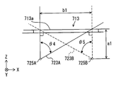
この光測距装置700の全体の水平方向の視野角は、図16に示すように、θ4+θ5になる。θ4は投受光ユニット720Aの視野角であり、θ5は投受光ユニット720Bの視野角である。θ4、θ5がそれぞれ62.5度であれば、光測距装置700の全体の水平方向の視野角は125度になる。
図17に示すように、2つの光路723A、723Bが窓713の外側面713aで重なっている場合、窓713の外側面713aの水平方向の最小長さb1は、式3で表すことができる。式3において、a1は、窓713の外側面713aから虚像発光点725A、725Bまでの距離である。なお、式3は、θ4≧θ5の場合であり、θ4<θ5の場合には、式3におけるθ4をθ5に置き換える。
(式3) b1=a1*tan(θ4)
この第7実施形態のように、投受光ユニット720A、720Bを2つにすれば、投受光ユニットを3つ備える場合よりも製造コストを安価にできる。
(式3) b1=a1*tan(θ4)
この第7実施形態のように、投受光ユニット720A、720Bを2つにすれば、投受光ユニットを3つ備える場合よりも製造コストを安価にできる。
<第8実施形態>
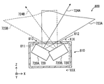
図18に示すように、第8実施形態の光測距装置800は、第7実施形態と同じ2つの投受光ユニット720A、720Bを備えている。これら2つの投受光ユニット720A、720Bは筐体810に収容されている。
図18に示すように、第8実施形態の光測距装置800は、第7実施形態と同じ2つの投受光ユニット720A、720Bを備えている。これら2つの投受光ユニット720A、720Bは筐体810に収容されている。
筐体810は、直方体形状である点では第7実施形態の筐体710と同じである。ただし、筐体810は、2つの投受光ユニット720A、720Bを互いに異なる鉛直方向位置に配置できるように、上下方向の空間が確保されている。
図18に示すように、2つの投受光ユニット720A、720Bは、Y軸方向から見た場合、すなわち、鉛直方向から見た場合、部分的に重なっている。このような配置が可能である理由は、図19に示すように、2つの投受光ユニット720A、720Bは、鉛直方向位置が互いに重ならないように配置されているからである。
この光測距装置800の場合でも、2つの光路723A、723Bが組み合わせられることにより、光測距装置800の全体の水平方向の視野角は、1つの投受光ユニット720A、720Bの視野角よりも、水平方向に広くなっている。光測距装置800の全体の水平方向の視野角は、第7実施形態と同様に、125度である。
この第8実施形態の光測距装置800でも、1つの投受光ユニット720A、720B、の視野角よりも光測距装置800の全体の視野角が広がっている方向は、水平方向である。
なお、図19では、鉛直方向にも、視野が広がっているように見える。しかし、図20は、光測距装置800において投受光ユニット720A、720Bの光路723A、723Bの全体を示す図であり、この図20に示すように、2つの光路723A、723Bの鉛直方向はほぼ重なっているとみなすことができる。よって、この第8実施形態において、鉛直方向は、1つの投受光ユニット720A、720Bの視野角よりも装置全体の視野角が広がっている方向ではない。
投射光が拡散光である場合、それぞれの光路723A、723Bを、図20のように、xz平面に平行な方向からみた場合には、それらの光路723A、723Bは、どちらも光測距装置800から離隔するほど、Y軸方向の幅が広くなる形状である。この形状の場合、2つの光路723A、723Bは、ほぼ重なっているとみなすことができる。このことからも、鉛直方向は、1つの投受光ユニット720A、720Bの視野角よりも装置全体の視野角が広がっている方向ではない。
図19に示すように、この第8実施形態では、投受光ユニット720A、720BのY軸方向の位置が互いに異なっているため、2つの光路723A、723Bは開口面812において重なっていない。
しかしながら、図18に示すように、2つの光路723A、723BをY軸方向から見た場合には、2つの光路723A、723Bは、開口面812の位置で重なっている。また、Y軸方向から見ると、光軸724A、724Bも一点において重なっている。
なお、Y軸方向は、第8実施形態では、2つの光路723A、723Bが組み合わせられることにより光測距装置800の全体の水平方向の視野角が、1つの投受光ユニット720A、720Bの視野角よりも広くなっている方向に垂直な方向である。
Y軸方向から見た場合に2つの光路723A、723Bが開口面812の位置で重なっている。よって、本実施形態でも、開口面812のX軸方向の長さは、Y軸方向から見た場合に2つの光路723A、723Bが開口面812の位置で重なっていない場合に比較して短くなっている。
<第9実施形態>
図21に第9実施形態の光測距装置900を示す。光測距装置900は、第1実施形態の投受光ユニット20に代えて、投受光ユニット920を備える。よって、投受光ユニット920の投受光部に相当する。
図21に第9実施形態の光測距装置900を示す。光測距装置900は、第1実施形態の投受光ユニット20に代えて、投受光ユニット920を備える。よって、投受光ユニット920の投受光部に相当する。
図21には1つの投受光ユニット920のみを示しているが、光測距装置900は、3つの投受光ユニット920を備えており、それら3つの投受光ユニット920は、それぞれ、3つの投受光ユニット20A、20B、20Cの位置に配置されている。これら3つの投受光ユニット920は筐体10に配置されている。筐体10は、第1実施形態と同じであるので、前側壁部11に、開口面12が形成されており、その開口面12に窓13が取り付けられている。
投受光ユニット920は、上側投光部921Aと下側投光部921Bの2つの投光部921と、1つの受光部922を備える。これらは、1つのユニット筐体929に収容されている。上側投光部921A、下側投光部921B、受光部922は、この順番で、Y軸方向の上方向から順に、Y軸方向に並んで配置されている。
上側投光部921A、下側投光部921Bは、いずれも、発光素子9211と投光レンズ9212を備えている。2つの発光素子9211は、いずれも、投射光を投光レンズ9212に向けて投光する。2つの投光レンズ9212は、いずれも、投射光を偏向して出力する。また、2つの投光レンズ9212は、いずれも、光軸が水平方向となるように配置されている。
上側投光部921Aと下側投光部921Bとでは、投光レンズ9212に対する発光素子9211の相対位置は相違する。上側投光部921Aは、発光素子9211において投射光が出力される部分が、投光レンズ9212の光軸よりも上側に位置している。よって、上側投光部921Aの視野角925Aは、投光レンズ9212の光軸よりも下側に形成される。
一方、下側投光部921Bは、発光素子9211において投射光が出力される部分が、投光レンズ9212の光軸よりも下側に位置している。よって、下側投光部921Bの視野角925Bは、投光レンズ9212の光軸よりも上側に形成される。なお、上側投光部921Aの視野角925A、下側投光部921Bの視野角925Bは、図21に示すように、投射光の光路が広がる角度を意味する。上側投光部921Aの光路923Aと下側投光部921Bの光路923Bは、開口面12において、垂直方向の位置が完全に重なっている。
受光部922は、受光レンズ9221と受光素子と9222を備える。受光レンズ9221は、上側投光部921Aが投光した投射光により生じた反射光、および、下側投光部921Bが投光した投射光により生じた反射光を受光素子9222に集光する。受光素子9222は、受光レンズ9221により集光された反射光を検出する。
この第9実施形態の投受光ユニット920は、2つの投光部921A、921Bを備えている。よって、投光部921が1つである場合と同じ検知距離を保持したまま垂直方向の視野を広げる、あるいは、垂直方位数を増やすことができる。
加えて、上側投光部921Aの光路923Aと下側投光部921Bの光路923Bは、開口面12において垂直方向の位置が完全に重なっている。これにより、光路923A、923Bの垂直方向の位置が開口面12において重ならない場合に比較して、開口面12の垂直方向のサイズを小さくすることができる。
なお、この投受光ユニット920の水平方向の視野角には特に制限はない。よって、投受光ユニット920の水平方向の視野角を、これまでの実施形態で示した投受光ユニット20、120、720のいずれかと同じにして、この投受光ユニット920を投受光ユニット20、120、720に代えて用いることができる。
<第10実施形態>
図22に第10実施形態の光測距装置1000を示す。第10実施形態の光測距装置1000は、第1実施形態の光測距装置1が備える3つの投受光ユニット20A、20B、20Cの視野角を変更した装置である。第1実施形態から、3つの投受光ユニット20の視野角を変更したのみであることから、詳細な構成の図示は省略し、便宜上、第1実施形態と同じ符号を用いて説明する。
図22に第10実施形態の光測距装置1000を示す。第10実施形態の光測距装置1000は、第1実施形態の光測距装置1が備える3つの投受光ユニット20A、20B、20Cの視野角を変更した装置である。第1実施形態から、3つの投受光ユニット20の視野角を変更したのみであることから、詳細な構成の図示は省略し、便宜上、第1実施形態と同じ符号を用いて説明する。
光測距装置1000が備える3つの投受光ユニット20A、20B、20Cは、それぞれ、図22に示す光路1023A、1023B、1023Cを形成する。前述したように、光測距装置1000は、第1実施形態から3つの投受光ユニット20の視野角を変更したのみである。よって、これらの光路1023A、1023B、1023Cは、開口面12で互いに重なっており、また、これらの光路1023A、1023B、1023Cの光軸は、一点において重なっている。
第1実施形態から、3つの投受光ユニット20の視野角を変更したのみである点では、第2実施形態と同じである。第2実施形態との違いは、第2実施形態では、3つの光路123A、123B、123Cのうち、装置全体の検知角度範囲の端に向かう光路123A、123Cが、装置全体の検知角度範囲の正面方向に向かう光路123Bよりも狭くなっていた。
これとは反対に、第10実施形態の光測距装置1000は、装置全体の検知角度範囲の正面方向に向かう光路1023Bが、装置全体の検知角度範囲の端に向かう光路1023A、1023Cよりも狭くなっている。
図22に示すθ6、θ7、θ8は、それぞれ、第1実施形態のθ1、θ2、θ3に対応している。つまり、θ7は、投受光ユニット20Aの水平方向の視野角であり、θ8は、投受光ユニット20Cの水平方向の視野角である。θ6は、投受光ユニット20Bの水平方向の視野角のうち、投受光ユニット20A、20Cの水平方向の視野角と重複していない範囲の角度である。
光路1023Bが相対的に狭くなっているので、図22に示すように、第2実施形態とは逆に、装置全体の検知角度範囲の正面方向となる検知範囲1027Bの検知距離が、装置全体の検知角度範囲の端部すなわち最も正面方向から離れた部分となる検知範囲1027A、1027Cの検知距離よりも長くなっている。なお、検知範囲1027A、1027B、1027Cは、それぞれ、投受光ユニット20A、20B、20Cの検知範囲である。
この第10実施形態の光測距装置1000は、図23に示すように、車両40の前端面に取り付けられて、車両40の進行方向前方に検知範囲を形成する。この光測距装置1000を車両の前端面に取り付けると、車両40の正面方向の検知距離を、車両40の斜め前方の検知距離よりも長くすることができる。
以上、実施形態を例示したが、本開示の技術的思想は、次の変形例を含む様々な実施形態とした具現化できる。
<変形例2>
前述の実施形態では、投受光ユニット20、120、720、920を、2つ、あるいは3つ備えていたが、投受光ユニット20、120、720、920の数は4つ以上でもよい。
前述の実施形態では、投受光ユニット20、120、720、920を、2つ、あるいは3つ備えていたが、投受光ユニット20、120、720、920の数は4つ以上でもよい。
<変形例3>
第6実施形態の窓613は内側の面が凹形状であったが、これとは反対に外側の面が凹面となっている凹レンズ形状でもよい。
第6実施形態の窓613は内側の面が凹形状であったが、これとは反対に外側の面が凹面となっている凹レンズ形状でもよい。
<変形例4>
フレネル反射の抑制を目的とする場合、投受光ユニット20A、20B、20Cの光路23A、23B、23Cが開口面12で互いに重なる必要はない。よって、たとえば、第5実施形態において、投受光ユニット20A、20Cの位置を入れ替えても良い。
フレネル反射の抑制を目的とする場合、投受光ユニット20A、20B、20Cの光路23A、23B、23Cが開口面12で互いに重なる必要はない。よって、たとえば、第5実施形態において、投受光ユニット20A、20Cの位置を入れ替えても良い。
<変形例5>
投受光ユニット20A、20B、20Cに代えて、投受光ユニット120A、120B、120Cを用いてもよい。
投受光ユニット20A、20B、20Cに代えて、投受光ユニット120A、120B、120Cを用いてもよい。
<変形例6>
第2実施形態において、投受光ユニット120A、120B、120Cに代えて、投受光ユニット20A、20B、20Cを使用し、投受光ユニット20Bの発光素子211の発光パワーを投受光ユニット20A、20Cの発光素子211よりも低くしてもよい。
第2実施形態において、投受光ユニット120A、120B、120Cに代えて、投受光ユニット20A、20B、20Cを使用し、投受光ユニット20Bの発光素子211の発光パワーを投受光ユニット20A、20Cの発光素子211よりも低くしてもよい。
このようにしても、光測距装置の全体の検知角度範囲の端部を視野角とする投受光ユニット20A、20Cの検知距離を、光測距装置の正面方向を視野角とする投受光ユニット20Bよりも長くできる。
<変形例7>
第10実施形態の光測距装置1000を車両40の後端面に取り付けてもよい。
第10実施形態の光測距装置1000を車両40の後端面に取り付けてもよい。
<変形例8>
第9実施形態では、発光素子9211を投光レンズ9212の光軸よりも上方向あるいは下方向にずらしていた。これに代えて、発光素子9211を投光レンズ9212の光軸上に配置して、それら発光素子9211および投光レンズ9212を鉛直面内で上下方向に回転させてもよい。このようにしても、垂直方向の視野を広げる、あるいは、垂直方位数を増やすことができる。
第9実施形態では、発光素子9211を投光レンズ9212の光軸よりも上方向あるいは下方向にずらしていた。これに代えて、発光素子9211を投光レンズ9212の光軸上に配置して、それら発光素子9211および投光レンズ9212を鉛直面内で上下方向に回転させてもよい。このようにしても、垂直方向の視野を広げる、あるいは、垂直方位数を増やすことができる。
<変形例9>
第2実施形態において、投受光ユニット120Cをなしにしてもよい。この場合、図10に示す3つの検知範囲127A、127B、127Cのうち、車両40の後側方に向かう検知範囲127Aがなくなる。光測距装置100の測距結果を利用する上位のシステムによっては、車両40の後側方に存在する物体までの距離を測定する必要がない場合があり、その場合には、上述のように、投受光ユニット120Cをなしにすることになる。
第2実施形態において、投受光ユニット120Cをなしにしてもよい。この場合、図10に示す3つの検知範囲127A、127B、127Cのうち、車両40の後側方に向かう検知範囲127Aがなくなる。光測距装置100の測距結果を利用する上位のシステムによっては、車両40の後側方に存在する物体までの距離を測定する必要がない場合があり、その場合には、上述のように、投受光ユニット120Cをなしにすることになる。
投受光ユニット120Cをなしにする場合、投受光ユニット120Aは、光測距装置100の全体の検知角度範囲のうち最も正面方向から離れた方向を視野角とする投受光ユニットになる。この投受光ユニット120Aは、光測距装置100の正面方向を視野角とする投受光ユニット120Bよりも検知距離が長くなっていることになる。
また上位のシステムの要求仕様によっては、反対に、車両40の前側方に向かう検知範囲127Cが不要である可能性もある。この場合には、投受光ユニット120Aをなしとする。
<変形例10>
第10実施形態において、投受光ユニット20Aおよび20Cのいずれか一方をなしにしてもよい。この場合、図22に示す3つの検知範囲1027A、1027B、1027Cのうち、検知範囲1027A、1027Cのいずれかがなくなる。
第10実施形態において、投受光ユニット20Aおよび20Cのいずれか一方をなしにしてもよい。この場合、図22に示す3つの検知範囲1027A、1027B、1027Cのうち、検知範囲1027A、1027Cのいずれかがなくなる。
たとえば、第10実施形態において、投受光ユニット20Aをなしにする場合、投受光ユニット20Cは、光測距装置1000の全体の検知角度範囲のうち最も正面方向から離れた方向を視野角とする投受光ユニットになる。そして、光測距装置1000の正面方向を視野角とする投受光ユニット20Bは、投受光ユニット20Cと比較して、検知距離は長く、視野角は狭くなっていることになる。
Claims (15)
- 開口面を備えた筐体(10、710、810)と、
前記筐体に収容され、レーザ光である投射光を投光するとともに反射光を受光する複数の投受光部(20、120、720、920)とを備えた光測距装置であって、
複数の前記投受光部の各光路が組み合わせられることにより1つの前記投受光部の視野角よりも装置全体の視野角が広がっている方向に対して垂直な方向から見た場合に、複数の前記投受光部の光路が前記開口面の位置において互いに重なるように、複数の前記投受光部は前記筐体内に配置されている光測距装置。 - 請求項1において、
複数の前記投受光部は、複数の前記投受光部の光路が前記開口面において互いに重なるように前記筐体内に配置されている光測距装置。 - 請求項2において、
複数の前記投受光部は、複数の前記投受光部の光路が前記開口面において互いに重なることに加えて、複数の前記投受光部の光軸が互いに重なるように、前記筐体内に配置されている光測距装置。 - 請求項2または3において、
複数の前記投受光部の各光路が組み合わせられることにより、1つの前記投受光部の視野角よりも装置全体の視野角が水平方向に広がっており、
複数の前記投受光部は、水平方向に並んで配置されている光測距装置。 - 請求項1において、
複数の前記投受光部の各光路が組み合わせられることにより、1つの前記投受光部の視野角よりも装置全体の視野角が水平方向に広がっており、
複数の前記投受光部は、鉛直方向の位置が互いに異なる位置に配置されており、
複数の前記投受光部の光路は、前記開口面の位置において鉛直方向の位置が互いに異なる光測距装置。 - 請求項5において、
複数の前記投受光部は、複数の前記投受光部の光路が前記開口面の位置において互いに重なることに加えて、1つの前記投受光部の視野角よりも装置全体の視野角が広がっている方向に対して垂直な方向から見た場合に、複数の前記投受光部の光軸が互いに重なるように、前記筐体内に配置されている光測距装置。 - 請求項1~6のいずれか1項において、
前記投受光部(920)は、前記投射光を投光する投光部(921A、921B)を複数備え、
複数の前記投光部は、鉛直方向の位置が互いに異なり、かつ、それら複数の前記投光部の光路が前記開口面において互いに重なるように配置されている光測距装置。 - 請求項2~4のいずれか1項において、
複数の前記投受光部のうち、前記開口面における光路の水平方向の長さが最も大きい前記投受光部の視野角、および、この投受光部の虚像発光点と前記開口面との距離に基づいて定まる最小開口面内に、すべての光路が収まるように前記投受光部を配置した光測距装置。 - 請求項1~8のいずれか1項において、
前記開口面に取り付けられた光透過性カバー(313、413、513)を備え、
複数の前記投受光部の光軸がそれぞれ前記光透過性カバーに入射する角度である複数の入射角のうち少なくとも一つは、当該入射角を算出したものと同じ前記光軸と前記開口面との角度よりも小さく、かつ、複数の前記入射角は、いずれも、当該入射角を算出したものと同じ前記光軸と前記開口面との角度以下である光測距装置。 - 請求項9において、
前記光透過性カバー(313、413)は、前記開口面に対して、前記筐体の内部方向に突き出た形状である光測距装置。 - 請求項1~8のいずれか1項において、
前記開口面に取り付けられた、凹レンズ形状の光透過性カバー(613)を備える光測距装置。 - 開口面を備えた筐体(10)と、
前記筐体に収容され、レーザ光である投射光を投光するとともに反射光を受光する複数の投受光部(20A、20B、20C、120A、120B、120C)と、
前記開口面に取り付けられた光透過性カバー(313、413、513)とを備え、
複数の前記投受光部の光軸がそれぞれ前記光透過性カバーに入射する角度である複数の入射角のうち少なくとも一つは、当該入射角を算出したものと同じ前記光軸と前記開口面との角度よりも小さく、かつ、複数の前記入射角は、いずれも、当該入射角を算出したものと同じ前記光軸と前記開口面との角度以下である光測距装置。 - 請求項1~12のいずれか1項において、
前記光測距装置の全体の検知角度範囲のうち最も正面方向から離れた部分を視野角とする前記投受光部は、前記光測距装置の正面方向を視野角とする前記投受光部よりも検知距離が長くなっている光測距装置。 - 請求項13において、
光軸が相対的に前記正面方向から離れている前記投受光部は、前記光軸が相対的に前記正面方向に近い前記投受光部よりも視野角が狭くなっている光測距装置。 - 請求項1~12のいずれか1項において、
前記光測距装置の正面方向を視野角とする前記投受光部は、前記光測距装置の全体の検知角度範囲のうち最も正面方向から離れた部分を視野角とする前記投受光部と比較して、検知距離は長く、視野角は狭くなっている光測距装置。
Priority Applications (2)
| Application Number | Priority Date | Filing Date | Title |
|---|---|---|---|
| DE112016006285.0T DE112016006285B4 (de) | 2016-01-22 | 2016-12-26 | Optische Abstandsmessvorrichtung |
| US16/071,330 US11226401B2 (en) | 2016-01-22 | 2016-12-26 | Optical distance measuring apparatus |
Applications Claiming Priority (4)
| Application Number | Priority Date | Filing Date | Title |
|---|---|---|---|
| JP2016011109 | 2016-01-22 | ||
| JP2016-011109 | 2016-01-22 | ||
| JP2016221886A JP6520894B2 (ja) | 2016-01-22 | 2016-11-14 | 光測距装置 |
| JP2016-221886 | 2016-11-14 |
Publications (1)
| Publication Number | Publication Date |
|---|---|
| WO2017126294A1 true WO2017126294A1 (ja) | 2017-07-27 |
Family
ID=59361700
Family Applications (1)
| Application Number | Title | Priority Date | Filing Date |
|---|---|---|---|
| PCT/JP2016/088606 Ceased WO2017126294A1 (ja) | 2016-01-22 | 2016-12-26 | 光測距装置 |
Country Status (2)
| Country | Link |
|---|---|
| US (1) | US11226401B2 (ja) |
| WO (1) | WO2017126294A1 (ja) |
Cited By (1)
| Publication number | Priority date | Publication date | Assignee | Title |
|---|---|---|---|---|
| CN109029453A (zh) * | 2018-07-13 | 2018-12-18 | 南方科技大学 | 熔覆头姿态路径规划方法、装置、终端、存储介质及系统 |
Families Citing this family (3)
| Publication number | Priority date | Publication date | Assignee | Title |
|---|---|---|---|---|
| US11248767B2 (en) | 2018-03-05 | 2022-02-15 | Koito Manufacturing Co., Ltd. | Sensor system, sensor module, and lamp device |
| WO2021196194A1 (zh) * | 2020-04-03 | 2021-10-07 | 深圳市速腾聚创科技有限公司 | 激光收发系统、激光雷达及自动驾驶设备 |
| JP2023183316A (ja) * | 2022-06-15 | 2023-12-27 | 富士フイルムビジネスイノベーション株式会社 | 光測距装置及び画像形成装置 |
Citations (8)
| Publication number | Priority date | Publication date | Assignee | Title |
|---|---|---|---|---|
| JPS61149876A (ja) * | 1984-12-24 | 1986-07-08 | Meisei Electric Co Ltd | 測距用信号の送信装置 |
| US4802096A (en) * | 1987-05-14 | 1989-01-31 | Bell & Howell Company | Controlled direction non-contact detection system for automatic guided vehicles |
| JPH06242224A (ja) * | 1993-02-23 | 1994-09-02 | Sumitomo Electric Ind Ltd | 車載用障害物検知装置 |
| JPH08114446A (ja) * | 1994-10-18 | 1996-05-07 | Mitsubishi Automob Eng Co Ltd | 測距センサの車体取付構造 |
| JPH1114747A (ja) * | 1997-06-25 | 1999-01-22 | Honda Motor Co Ltd | 車両の物体検知装置 |
| WO2001084594A1 (en) * | 2000-05-02 | 2001-11-08 | Prospects, Corp. | Multifaceted sensor system |
| JP2003329773A (ja) * | 2002-05-10 | 2003-11-19 | Hitachi Ltd | 複数の距離検知センサを設置した車両制御装置 |
| JP2014055860A (ja) * | 2012-09-13 | 2014-03-27 | Ricoh Co Ltd | 距離測定装置 |
Family Cites Families (10)
| Publication number | Priority date | Publication date | Assignee | Title |
|---|---|---|---|---|
| DE3513350C1 (de) * | 1985-04-13 | 1986-06-26 | Messerschmitt-Bölkow-Blohm GmbH, 8012 Ottobrunn | Einrichtung zur Erkennung und Richtungsdetektion von optischer Strahlung,insbes. Laserstrahlung |
| US6087975A (en) | 1997-06-25 | 2000-07-11 | Honda Giken Kogyo Kabushiki Kaisha | Object detecting system for vehicle |
| US6943873B2 (en) * | 2001-07-17 | 2005-09-13 | Bae Systems Integrated Defense Solutions Inc. | Fiber optical laser detection and ranging system |
| US8384559B2 (en) * | 2010-04-13 | 2013-02-26 | Silicon Laboratories Inc. | Sensor device with flexible interface and updatable information store |
| US9400170B2 (en) * | 2010-04-21 | 2016-07-26 | Faro Technologies, Inc. | Automatic measurement of dimensional data within an acceptance region by a laser tracker |
| US9892298B2 (en) * | 2012-02-06 | 2018-02-13 | Cognex Corporation | System and method for expansion of field of view in a vision system |
| CA2871502C (en) * | 2012-04-26 | 2021-06-08 | Neptec Design Group Ltd. | High speed 360 degree scanning lidar head |
| JP6032416B2 (ja) | 2012-12-10 | 2016-11-30 | コニカミノルタ株式会社 | レーザレーダ |
| US10436904B2 (en) * | 2015-04-15 | 2019-10-08 | The Boeing Company | Systems and methods for modular LADAR scanning |
| US10408940B2 (en) * | 2016-09-25 | 2019-09-10 | James Thomas O'Keeffe | Remote lidar with coherent fiber optic image bundle |
-
2016
- 2016-12-26 WO PCT/JP2016/088606 patent/WO2017126294A1/ja not_active Ceased
- 2016-12-26 US US16/071,330 patent/US11226401B2/en active Active
Patent Citations (8)
| Publication number | Priority date | Publication date | Assignee | Title |
|---|---|---|---|---|
| JPS61149876A (ja) * | 1984-12-24 | 1986-07-08 | Meisei Electric Co Ltd | 測距用信号の送信装置 |
| US4802096A (en) * | 1987-05-14 | 1989-01-31 | Bell & Howell Company | Controlled direction non-contact detection system for automatic guided vehicles |
| JPH06242224A (ja) * | 1993-02-23 | 1994-09-02 | Sumitomo Electric Ind Ltd | 車載用障害物検知装置 |
| JPH08114446A (ja) * | 1994-10-18 | 1996-05-07 | Mitsubishi Automob Eng Co Ltd | 測距センサの車体取付構造 |
| JPH1114747A (ja) * | 1997-06-25 | 1999-01-22 | Honda Motor Co Ltd | 車両の物体検知装置 |
| WO2001084594A1 (en) * | 2000-05-02 | 2001-11-08 | Prospects, Corp. | Multifaceted sensor system |
| JP2003329773A (ja) * | 2002-05-10 | 2003-11-19 | Hitachi Ltd | 複数の距離検知センサを設置した車両制御装置 |
| JP2014055860A (ja) * | 2012-09-13 | 2014-03-27 | Ricoh Co Ltd | 距離測定装置 |
Cited By (2)
| Publication number | Priority date | Publication date | Assignee | Title |
|---|---|---|---|---|
| CN109029453A (zh) * | 2018-07-13 | 2018-12-18 | 南方科技大学 | 熔覆头姿态路径规划方法、装置、终端、存储介质及系统 |
| CN109029453B (zh) * | 2018-07-13 | 2022-05-17 | 南方科技大学 | 熔覆头姿态路径规划方法、装置、终端、存储介质及系统 |
Also Published As
| Publication number | Publication date |
|---|---|
| US20190293762A1 (en) | 2019-09-26 |
| US11226401B2 (en) | 2022-01-18 |
Similar Documents
| Publication | Publication Date | Title |
|---|---|---|
| JP6520894B2 (ja) | 光測距装置 | |
| WO2017126294A1 (ja) | 光測距装置 | |
| JP6340851B2 (ja) | 物体検出装置及びセンシング装置 | |
| EP2672295B1 (en) | Photoelectric sensor | |
| JP2000242406A (ja) | 光走査型タッチパネル | |
| US10773656B2 (en) | Surrounding circumstance monitoring apparatus | |
| CN114174763A (zh) | 测距装置和测距系统 | |
| EP2910983B1 (en) | Photoelectric sensor | |
| JP7103694B2 (ja) | レーザー探知機 | |
| JP5251641B2 (ja) | 光電センサ | |
| KR20210084635A (ko) | 자율 주행 차량 | |
| EP3364229B1 (en) | Optical-scanning-type object detection device | |
| JP2025028363A (ja) | センサ装置 | |
| CN111433650B (zh) | 单稳态或准单稳态激光测距仪的保护 | |
| KR102001109B1 (ko) | 라이다용 레이저 발광 장치 및 균일 에너지 밀도 투사 렌즈 | |
| JP4531081B2 (ja) | 光走査型タッチパネル | |
| JP2017033860A (ja) | 回帰反射形光電センサ | |
| US20220283304A1 (en) | Light source module and lidar device | |
| US10753806B2 (en) | Non-contact temperature measuring device | |
| JP4143759B2 (ja) | 光学式座標入力装置 | |
| JP2013210263A (ja) | センサ装置 | |
| JP5058928B2 (ja) | 光電センサ | |
| US20190017878A1 (en) | Non-contact temperature measuring device | |
| CN212275965U (zh) | 遮光组件 | |
| CN119856105B (zh) | 一种遮光组件、探测装置和终端 |
Legal Events
| Date | Code | Title | Description |
|---|---|---|---|
| 121 | Ep: the epo has been informed by wipo that ep was designated in this application |
Ref document number: 16886532 Country of ref document: EP Kind code of ref document: A1 |
|
| WWE | Wipo information: entry into national phase |
Ref document number: 112016006285 Country of ref document: DE |
|
| 122 | Ep: pct application non-entry in european phase |
Ref document number: 16886532 Country of ref document: EP Kind code of ref document: A1 |
|
| WWG | Wipo information: grant in national office |
Ref document number: 112016006285 Country of ref document: DE |