WO2017126190A1 - ガスセンサ - Google Patents
ガスセンサ Download PDFInfo
- Publication number
- WO2017126190A1 WO2017126190A1 PCT/JP2016/082722 JP2016082722W WO2017126190A1 WO 2017126190 A1 WO2017126190 A1 WO 2017126190A1 JP 2016082722 W JP2016082722 W JP 2016082722W WO 2017126190 A1 WO2017126190 A1 WO 2017126190A1
- Authority
- WO
- WIPO (PCT)
- Prior art keywords
- electrode
- gas
- sensor
- film thickness
- monitor
- Prior art date
- Legal status (The legal status is an assumption and is not a legal conclusion. Google has not performed a legal analysis and makes no representation as to the accuracy of the status listed.)
- Ceased
Links
Images

Classifications
-
- G—PHYSICS
- G01—MEASURING; TESTING
- G01N—INVESTIGATING OR ANALYSING MATERIALS BY DETERMINING THEIR CHEMICAL OR PHYSICAL PROPERTIES
- G01N27/00—Investigating or analysing materials by the use of electric, electrochemical, or magnetic means
- G01N27/26—Investigating or analysing materials by the use of electric, electrochemical, or magnetic means by investigating electrochemical variables; by using electrolysis or electrophoresis
- G01N27/416—Systems
- G01N27/417—Systems using cells, i.e. more than one cell and probes with solid electrolytes
- G01N27/419—Measuring voltages or currents with a combination of oxygen pumping cells and oxygen concentration cells
-
- G—PHYSICS
- G01—MEASURING; TESTING
- G01N—INVESTIGATING OR ANALYSING MATERIALS BY DETERMINING THEIR CHEMICAL OR PHYSICAL PROPERTIES
- G01N27/00—Investigating or analysing materials by the use of electric, electrochemical, or magnetic means
- G01N27/26—Investigating or analysing materials by the use of electric, electrochemical, or magnetic means by investigating electrochemical variables; by using electrolysis or electrophoresis
- G01N27/403—Cells and electrode assemblies
- G01N27/406—Cells and probes with solid electrolytes
- G01N27/407—Cells and probes with solid electrolytes for investigating or analysing gases
- G01N27/4071—Cells and probes with solid electrolytes for investigating or analysing gases using sensor elements of laminated structure
- G01N27/4072—Cells and probes with solid electrolytes for investigating or analysing gases using sensor elements of laminated structure characterized by the diffusion barrier
-
- G—PHYSICS
- G01—MEASURING; TESTING
- G01N—INVESTIGATING OR ANALYSING MATERIALS BY DETERMINING THEIR CHEMICAL OR PHYSICAL PROPERTIES
- G01N27/00—Investigating or analysing materials by the use of electric, electrochemical, or magnetic means
- G01N27/26—Investigating or analysing materials by the use of electric, electrochemical, or magnetic means by investigating electrochemical variables; by using electrolysis or electrophoresis
- G01N27/403—Cells and electrode assemblies
- G01N27/406—Cells and probes with solid electrolytes
- G01N27/407—Cells and probes with solid electrolytes for investigating or analysing gases
- G01N27/409—Oxygen concentration cells
-
- G—PHYSICS
- G01—MEASURING; TESTING
- G01N—INVESTIGATING OR ANALYSING MATERIALS BY DETERMINING THEIR CHEMICAL OR PHYSICAL PROPERTIES
- G01N27/00—Investigating or analysing materials by the use of electric, electrochemical, or magnetic means
- G01N27/26—Investigating or analysing materials by the use of electric, electrochemical, or magnetic means by investigating electrochemical variables; by using electrolysis or electrophoresis
- G01N27/403—Cells and electrode assemblies
- G01N27/406—Cells and probes with solid electrolytes
- G01N27/407—Cells and probes with solid electrolytes for investigating or analysing gases
- G01N27/41—Oxygen pumping cells
-
- G—PHYSICS
- G01—MEASURING; TESTING
- G01N—INVESTIGATING OR ANALYSING MATERIALS BY DETERMINING THEIR CHEMICAL OR PHYSICAL PROPERTIES
- G01N33/00—Investigating or analysing materials by specific methods not covered by groups G01N1/00 - G01N31/00
- G01N33/0004—Gaseous mixtures, e.g. polluted air
- G01N33/0009—General constructional details of gas analysers, e.g. portable test equipment
- G01N33/0027—General constructional details of gas analysers, e.g. portable test equipment concerning the detector
- G01N33/0036—General constructional details of gas analysers, e.g. portable test equipment concerning the detector specially adapted to detect a particular component
Definitions
- the present disclosure relates to a gas sensor that measures a specific gas component concentration in a gas to be measured.
- the oxygen concentration in the gas to be measured is adjusted to a predetermined concentration or lower, and then the sensor electrode that can decompose the specific gas component is used.
- the concentration of the specific gas component in the measurement gas is detected.
- a monitor electrode different from the sensor electrode is used to detect the concentration of residual oxygen in the gas to be measured after the oxygen concentration is adjusted, and the specific gas component is detected. The influence of the residual oxygen concentration on the detection of the concentration is corrected.
- an oxygen pump cell, an oxygen monitor cell, and a sensor cell are formed by a solid electrolyte body and a pair of electrodes.
- the oxygen monitor cell detects the residual oxygen in the gas to be measured after the oxygen concentration is adjusted by the oxygen pump cell
- the sensor cell detects the residual oxygen and the specific gas component in the gas to be measured after the oxygen concentration is adjusted by the oxygen pump cell. To detect. Then, the concentration of the specific gas component in the measurement gas is detected by subtracting the output of the oxygen monitor cell from the output of the sensor cell.
- an electrode that exposes the gas to be measured (referred to as a monitor electrode) that constitutes the oxygen monitor cell and an electrode that constitutes the sensor cell and that is exposed to the gas to be measured (referred to as a sensor electrode). It is arrange
- This disclosure is obtained by providing a gas sensor that can appropriately correct the influence of residual oxygen and improve the detection accuracy of a specific gas component.
- One aspect of the present disclosure includes one or more solid electrolyte plates having oxygen ion conductivity; A gas chamber to be measured formed adjacent to the solid electrolyte plate; A pump electrode provided on the surface of the solid electrolyte plate and exposed to the gas to be measured in the gas chamber to be measured; A monitor electrode and a sensor electrode provided adjacent to each other at a position downstream of the flow of the gas to be measured with respect to the pump electrode on the surface of the solid electrolyte plate, and exposed to the gas to be measured in the gas chamber to be measured; One or more reference electrodes provided on the surface of the solid electrolyte plate and exposed to a reference gas; A heater that is disposed to face the solid electrolyte plate and heats the solid electrolyte plate; A pump cell that adjusts the oxygen concentration of the gas to be measured in the gas chamber to be measured when a voltage is applied between the pump electrode and the reference electrode via a part of the solid electrolyte plate; A current flowing through a part of the solid electrolyte plate between the monitor electrode and
- a monitor cell Residual oxygen and specific gas in the gas to be measured after detecting the current flowing through a part of the solid electrolyte plate between the sensor electrode and the reference electrode and adjusting the oxygen concentration by the pump electrode
- a sensor cell for detecting the component In the gas sensor, the maximum film thickness of the sensor electrode is larger than the maximum film thickness of the monitor electrode, and the difference between the maximum film thickness of the sensor electrode and the maximum film thickness of the monitor electrode is 4 ⁇ m or more and 30 ⁇ m or less.
- the relationship between the maximum film thickness of the monitor electrode used to detect the residual oxygen concentration of the gas to be measured and the maximum film thickness of the sensor electrode used to detect the specific gas component concentration is defined. . Specifically, the maximum film thickness of the sensor electrode is larger than the maximum film thickness of the monitor electrode.
- the gas to be measured after the oxygen concentration is adjusted by the pump electrode is in contact with the monitor electrode and the sensor electrode. In the monitor electrode, residual oxygen in the measurement gas is decomposed, while in the sensor electrode, residual oxygen and a specific gas component in the measurement gas are decomposed.
- the monitor electrode only needs to contain a component that decomposes oxygen, whereas the sensor electrode needs to contain a component that decomposes a specific gas component in addition to a component that decomposes oxygen.
- disassembles oxygen in a sensor electrode becomes relatively smaller compared with the component which decomposes
- the oxygen decomposition capacity per unit volume of the sensor electrode is smaller than the oxygen decomposition capacity per unit volume of the monitor electrode.
- the detection accuracy of the specific gas component by the gas sensor can be improved as a result.
- the influence of the residual oxygen on the detection of the specific gas component can be corrected by subtracting the output of the monitor cell from the output of the sensor cell.
- the difference between the maximum film thickness of the sensor electrode and the maximum film thickness of the monitor electrode is 4 ⁇ m or more and 30 ⁇ m or less. If the maximum film thickness of the sensor electrode is too larger than the maximum film thickness of the monitor electrode, the sensitivity of the sensor electrode to specific gas components increases, while the sensitivity of the sensor electrode to residual oxygen is higher than the sensitivity of the monitor electrode to residual oxygen. May be too high. Therefore, when the difference between the maximum film thickness of the sensor electrode and the maximum film thickness of the monitor electrode is 30 ⁇ m or less, the difference between the sensitivity of the sensor electrode to residual oxygen and the sensitivity of the monitor electrode to residual oxygen is greatly different. Can be prevented.
- the maximum film thickness of the sensor electrode needs to be 4 ⁇ m or more larger than the maximum film thickness of the monitor electrode.
- the gas sensor it is possible to appropriately correct the influence of residual oxygen and improve the detection accuracy of the specific gas component.
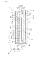
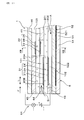
- Explanatory drawing which shows the state of the gas sensor when it is assembled
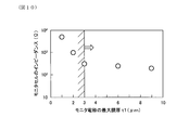
- the graph which shows the relationship between the maximum film thickness of a sensor electrode and the output current of a sensor cell concerning embodiment.
- the graph which shows the relationship between the maximum film thickness of a sensor electrode and the response time of a sensor cell concerning embodiment.
- the graph which shows the relationship between the maximum film thickness of a monitor electrode and the response time of a sensor cell concerning embodiment.
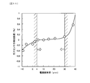
- the graph which shows the relationship between the maximum film thickness of a monitor electrode and the impedance of a monitor cell concerning embodiment.
- the graph which shows the relationship between the difference of the maximum film thickness of a sensor electrode and the maximum film thickness of a monitor electrode, and the detection error of a gas sensor concerning embodiment.
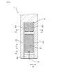
- Explanatory drawing which shows the cross section of the other gas sensor concerning embodiment.
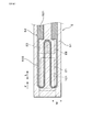
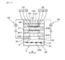
- Explanatory drawing which shows the cross section of a gas sensor by the XIII-XIII arrow of FIG. 12 concerning embodiment.
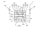
- the gas sensor 1 includes a solid electrolyte plate 2, a gas chamber 101 to be measured, a pump electrode 21, a monitor electrode 22, a sensor electrode 23, a reference electrode 24, a heater 5, a pump cell 31, and a monitor cell 32. And a sensor cell 33.
- the solid electrolyte plate 2 has oxygen ion conductivity.
- the gas chamber 101 to be measured is formed adjacent to the solid electrolyte plate 2.
- the pump electrode 21 is provided on the first surface 201, which is one surface of the solid electrolyte plate 2, and is exposed to the measured gas G in the measured gas chamber 101.
- the monitor electrode 22 and the sensor electrode 23 are provided adjacent to each other at a position downstream of the flow F of the gas to be measured G with respect to the pump electrode 21 on the first surface 201 of the solid electrolyte plate 2.
- the chamber 101 is exposed to the gas G to be measured.
- the reference electrode 24 is provided on the second surface 202 which is the other surface of the solid electrolyte plate 2 and is exposed to the reference gas A.
- the heater 5 is disposed to face the solid electrolyte plate 2 and heats the solid electrolyte plate 2.
- the pump cell 31 adjusts the oxygen concentration of the measurement gas G in the measurement gas chamber 101 when a voltage is applied between the pump electrode 21 and the reference electrode 24 via a part 2A of the solid electrolyte plate 2. Is.
- the monitor cell 32 detects the current flowing between the monitor electrode 22 and the reference electrode 24 via the part 2B of the solid electrolyte plate 2 and the gas G to be measured after the oxygen concentration is adjusted by the pump electrode 21. Residual oxygen is detected.
- the sensor cell 33 detects the current flowing through the part 2C of the solid electrolyte plate 2 between the sensor electrode 23 and the reference electrode 24, and the gas G to be measured after the oxygen concentration is adjusted by the pump electrode 21. Residual oxygen and specific gas components are detected.
- the maximum film thickness t2 of the sensor electrode 23 is larger than the maximum film thickness t1 of the monitor electrode 22, and the difference between the maximum film thickness t2 of the sensor electrode 23 and the maximum film thickness t1 of the monitor electrode 22 is 4 ⁇ m or more and 30 ⁇ m or less.
- illustration of the monitor electrode 22, the sensor electrode 23, etc. in FIG. 1, FIG. 2, etc. is conceptual, and does not show the actual film thickness etc. of the monitor electrode 22, the sensor electrode 23, etc.
- the gas sensor 1 is used by being disposed in an exhaust passage of an internal combustion engine in a vehicle, and detects the concentration of NOx (nitrogen oxide) as a specific gas component contained in the exhaust gas using the exhaust gas flowing through the exhaust passage as the gas to be measured G. To do.
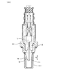
- the gas sensor 1 constitutes a sensor element and is formed in a long shape. A proximal end portion in the longitudinal direction L of the gas sensor 1 is held by an insulator 12, and the insulator 12 is held by a housing 13 attached to the internal combustion engine.
- a detection unit 11 into which the gas G to be measured flows is provided at the distal end portion in the longitudinal direction L of the gas sensor 1, and the detection unit 11 is covered by a protective cover 14 provided with a through hole 141. ing.
- the gas chamber 101 to be measured, the pump electrode 21, the monitor electrode 22, the sensor electrode 23, the reference electrode 24, the heater 5, the pump cell 31, the monitor cell 32, the sensor cell 33, and the like are arranged in the detection unit 11.
- the distal end side in the longitudinal direction L of the gas sensor 1 is the upstream side of the flow F of the measured gas G in the measured gas chamber 101, and the proximal end side in the longitudinal direction L of the gas sensor 1 is the measured gas. It becomes the downstream side of the flow F of the gas G to be measured in the chamber 101.
- the solid electrolyte plate 2 is made of yttria-stabilized zirconia, and only one is disposed in the gas sensor 1.
- a second insulating plate 42 is laminated on the first surface 201 of the solid electrolyte plate 2 with a notched first insulating plate 41 for forming the gas chamber 101 to be measured.
- the first insulating plate 41 and the second insulating plate 42 are made of an insulator such as alumina.
- the first insulating plate 41 is provided on the base end side portion in the longitudinal direction L and the both side portions in the width direction W on the first surface 201 of the solid electrolyte plate 2.
- An opening is formed in the distal end portion of the first insulating plate 41 in the longitudinal direction L, and a diffusion resistor 44 made of a porous body is disposed in the opening.
- the measured gas chamber 101 is formed between the first surface 201 of the solid electrolyte plate 2 and the second insulating plate 42 so as to be surrounded by the diffusion resistor 44 and the first insulating plate 41.
- the measured gas G flows into the measured gas chamber 101 via the diffusion resistor 44.
- the pump electrode 21, the monitor electrode 22, the sensor electrode 23, and the reference electrode 24 are provided on the same solid electrolyte plate 2.
- the pump electrode 21 is disposed at a position upstream of the flow F of the gas G to be measured in the gas chamber 101 to be measured and closer to the diffusion resistor 44 than the monitor electrode 22 and the sensor electrode 23.
- the monitor electrode 22 and the sensor electrode 23 are formed to have the same size and are disposed at the same position from the pump electrode 21.
- the arrangement conditions of the monitor electrode 22 and the sensor electrode 23 are made equal to the flow F of the measurement gas G after passing through the arrangement position of the pump electrode 21 in the measurement gas chamber 101.
- the interval w1 between the monitor electrode 22 and the sensor electrode 23 arranged on the solid electrolyte plate 2 is preferably 1.0 mm or less.
- One reference electrode 24 is provided at a position facing the pump electrode 21, the monitor electrode 22, and the sensor electrode 23 as a whole. In addition, three reference electrodes 24 can be separately provided at positions facing the pump electrode 21, the monitor electrode 22, and the sensor electrode 23.
- the pump electrode 21 and the monitor electrode 22 are configured using a cermet material containing a metal component such as a Pt—Au alloy and a zirconia component that can decompose oxygen and not decompose a specific gas component.
- the sensor electrode 23 is configured using a cermet material containing a metal component such as a Pt—Rh alloy and a zirconia component that can decompose oxygen and a specific gas component.
- the reference electrode 24 is configured using a cermet material containing a metal component such as Pt and a zirconia component capable of decomposing oxygen.
- the heater 5 includes two ceramic substrates 51 such as alumina, and a conductor layer 52 embedded between the two ceramic substrates 51.
- the heater 5 is laminated on the second surface 202 of the solid electrolyte plate 2 via a third insulating plate 43 for forming a reference gas chamber 102 into which the atmosphere as the reference gas A is introduced.
- the third insulating plate 43 is made of an insulator such as alumina.
- the third insulating plate 43 is formed in a notch shape having an opening at the base end in the longitudinal direction L of the gas sensor 1.
- the reference gas chamber 102 is formed between the second surface 202 of the solid electrolyte plate 2 and the ceramic substrate 51 so as to be surrounded on three sides by the third insulating plate 43.
- the reference gas A flows into the reference gas chamber 102 from the proximal end portion in the longitudinal direction L of the gas sensor 1.
- the conductor layer 52 of the heater 5 connects the pair of lead parts 521 connected to the energization means outside the gas sensor 1 and the pair of lead parts 521, and is applied to the pair of lead parts 521.
- a heat generating portion 522 that generates heat when energized by voltage.
- the heat generating portion 522 mainly generates heat due to Joule heat.
- the pump electrode 21, the monitor electrode 22, and the sensor electrode 23 are heated to a desired operating temperature by the heat generated by the heat generating unit 522.
- the resistance value of the heat generating part 522 is larger than the resistance value of the lead part 521.
- the resistance value of the heat generating portion 522 can occupy 50% or more of the resistance value of the entire conductor layer 52.
- the heat generating portion 522 is provided at a position facing substantially the entire planar area where the pump electrode 21, the monitor electrode 22, and the sensor electrode 23 are disposed.
- the resistance value of the heat generating part 522 can be made larger than the resistance value of the lead part 521 by making the pattern wiring of the heat generating part 522 thinner than the pattern wiring of the lead part 521.
- the heat generating portion 522 is made smaller than the film thickness of the lead portion 521, and the heat generating portion 522 is made of a material having a specific resistance higher than that of the lead portion 521.
- the resistance value of 522 can be made larger than the resistance value of the lead portion 521.
- the resistance value of the heat generating part 522 can be made larger than the resistance value of the lead part 521 by combining techniques for changing the thickness, film thickness, constituent material, and the like of the pattern wiring.
- the pump cell 31 includes a pump electrode 21, a part of the reference electrode 24, a part 2A of the solid electrolyte plate 2 sandwiched between the pump electrode 21 and a part of the reference electrode 24, It is constituted by.
- a voltage application circuit 61 for applying a voltage between the electrodes 21 and 24 is provided.
- oxygen in the gas G to be measured that contacts the pump electrode 21 is decomposed and passed through the solid electrolyte plate 2. Oxygen ions permeate the reference electrode 24 and oxygen in the measurement gas G in the measurement gas chamber 101 is removed.
- the monitor cell 32 includes a monitor electrode 22, a part of the reference electrode 24, a part 2 ⁇ / b> B of the solid electrolyte plate 2 sandwiched between the monitor electrode 22 and a part of the reference electrode 24. It is constituted by. Between the monitor electrode 22 and the reference electrode 24, a current detection circuit for monitoring that detects a current flowing between the electrodes 22 and 24 in a state where a predetermined voltage is applied between the electrodes 22 and 24. 62 is provided. When residual oxygen in the measurement gas G that contacts the monitor electrode 22 is decomposed, oxygen ions permeate the reference electrode 24 through the solid electrolyte plate 2. At this time, the current flowing between the monitor electrode 22 and the reference electrode 24 via the part 2B of the solid electrolyte plate 2 is detected by the monitoring current detection circuit 62.
- the sensor cell 33 includes a sensor electrode 23, a part of the reference electrode 24, a part 2C of the solid electrolyte plate 2 sandwiched between the sensor electrode 23 and a part of the reference electrode 24, and It is constituted by. Between the sensor electrode 23 and the reference electrode 24, a current detection circuit for a sensor that detects a current flowing between the electrodes 23 and 24 in a state where a predetermined voltage is applied between the electrodes 23 and 24. 63 is provided. When residual oxygen and a specific gas component in the measurement gas G that contacts the sensor electrode 23 are decomposed, oxygen ions permeate the reference electrode 24 through the solid electrolyte plate 2.
- the current flowing between the sensor electrode 23 and the reference electrode 24 via the part 2C of the solid electrolyte plate 2 is detected by the sensor current detection circuit 63. Further, in the control unit that controls the operation of the gas sensor 1, the influence of the residual oxygen in the exhaust gas that is the gas G to be measured is corrected by subtracting the current output of the monitor cell 32 from the current output of the sensor cell 33. The concentration of NOx that is a specific gas component is obtained.
- the gas sensor 1 is formed by laminating the zirconia sheet constituting the solid electrolyte plate 2, the insulating plates 41, 42, 43, the diffusion resistor 44 and the heater 5, and firing the laminate. At this time, a paste of electrode materials constituting the pump electrode 21, the monitor electrode 22, the sensor electrode 23, and the reference electrode 24 is applied to the surface of the zirconia sheet in a flat shape. However, the metal component and the zirconia component in each of the electrodes 21, 22, 23, and 24 are not completely flatly distributed, and the surface of each of the electrodes 21, 22, 23, and 24 after firing has micro unevenness. Has occurred.
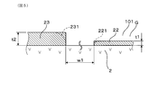
- the film thicknesses of the monitor electrode 22 and the sensor electrode 23 are shown as maximum film thicknesses t1 and t2.
- the monitor electrode 22 and the sensor electrode 23 are set so that the difference between the maximum film thickness and the minimum film thickness is 3 ⁇ m or less.
- the maximum film thicknesses t1 and t2 refer to the film thicknesses of the portions where the thicknesses are the largest in the respective electrodes 22 and 23 having uneven surface shapes.
- the surface of each electrode 22, 23 is formed with many depressed portions due to pores, and the maximum film thicknesses t1, t2 are selected from the portions excluding the depressed portions.
- the end portions 221 and 231 of the electrodes 22 and 23 are not formed in a right-angle shape, but are often formed in an arc shape (indicated by a two-dot chain line) as shown in FIG.
- the maximum film thicknesses t1 and t2 are measured as film thicknesses near the central portion excluding all the end portions 221 and 231 when the electrodes 22 and 23 are viewed in plan.
- the maximum film thicknesses t1 and t2 of the electrodes 22 and 23 can be measured by observation using an optical microscope or an electron microscope.
- the maximum film thicknesses t1 and t2 of the electrodes 22 and 23 can be measured by, for example, cutting the electrodes 22 and 23 by ion beam processing or the like, and observing the cut surfaces by SEM (scanning electron microscopy) or the like. .
- the maximum film thickness t2 of the sensor electrode 23 of the present embodiment is 5 ⁇ m or more and 35 ⁇ m or less, and the maximum film thickness t1 of the monitor electrode 22 of the present embodiment is 3 ⁇ m or more and 20 ⁇ m or less.
- the difference between the maximum film thickness t2 of the sensor electrode 23 and the maximum film thickness t1 of the monitor electrode 22 can be 5 ⁇ m or more and 10 ⁇ m.
- the metal components of the pump electrode 21 and the monitor electrode 22 are Pt—Au alloys having 99% by mass of Pt and 1% by mass of Au, and the metal components of the sensor electrode 23.
- the metal components of the sensor electrode 23 was a Pt—Rh alloy with Pt of 50 mass% and Rh of 50 mass%.
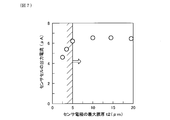
- FIG. 7 shows the results of testing the relationship between the maximum film thickness t2 ( ⁇ m) of the sensor electrode 23 and the output current ( ⁇ A) of the sensor cell 33.
- a plurality of gas sensors 1 having different maximum film thicknesses t2 of the sensor electrodes 23 were prepared, and the output current of the sensor cell 33 in each gas sensor 1 was measured.
- a gas to be measured G having a concentration of oxygen of 5%, a concentration of nitrogen monoxide (NO) of 2000 ppm, and the balance being nitrogen was introduced into the measured gas chamber 101 of each gas sensor 1.
- the output current of the sensor cell 33 is indicated as the output current of the sensor cell 33 when each gas sensor 1 detects the concentration of nitric oxide as a specific gas component.
- the maximum film thickness t1 of the monitor electrode 22 was 10 ⁇ m.
- the surface area of the sensor electrode 23 is reduced by decreasing the maximum film thickness t2 of the sensor electrode 23, the reaction point (contact frequency) between the sensor electrode 23 and nitric oxide is insufficient, and the gas chamber to be measured This is considered to be because the nitric oxide introduced into 101 is not completely decomposed.
- the maximum film thickness t2 of the sensor electrode 23 is preferably 5 ⁇ m or more.
- FIG. 8 shows the results of testing the relationship between the maximum film thickness t2 ( ⁇ m) of the sensor electrode 23 and the response time (s) of the sensor cell 33.
- a plurality of gas sensors 1 having different maximum film thicknesses t2 of the sensor electrodes 23 were prepared, and the response time of the sensor cell 33 in each gas sensor 1 was measured.
- a gas to be measured G having an oxygen concentration of 5%, a nitrogen monoxide (NO) concentration of 500 ppm, and the balance nitrogen was introduced into the measured gas chamber 101 of each gas sensor 1.
- a 10-90% response time was measured when the measurement gas G was switched to the measurement gas G having an oxygen concentration of 5%, a nitric oxide concentration of 0 ppm, and the balance being nitrogen.
- the maximum film thickness t1 of the monitor electrode 22 was 10 ⁇ m.
- the maximum film thickness t2 of the sensor electrode 23 is 35 ⁇ m or less. This is because in this range, nitric oxide adsorbed on the sensor electrode 23 is rapidly decomposed. It can also be seen that the response time of the sensor cell 33 increases as the maximum film thickness t2 of the sensor electrode 23 becomes larger than 35 ⁇ m. The reason for this is that as the maximum film thickness t2 of the sensor electrode 23 increases, the surface area of the sensor electrode 23, which is a porous body, increases, and the amount of nitric oxide adsorbed on the sensor electrode 23 increases. This is considered to be because the time required for the removal of nitric oxide from the electrode 23 becomes longer. In view of the need to keep the response time of the sensor cell 33 using the sensor electrode 23 short, the maximum film thickness t2 of the sensor electrode 23 is preferably 35 ⁇ m or less.
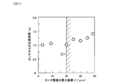
- FIG. 9 shows the results of testing the relationship between the maximum film thickness t1 ( ⁇ m) of the monitor electrode 22 and the response time (s) of the sensor cell 33.
- a plurality of gas sensors 1 having different maximum film thicknesses t1 of the monitor electrodes 22 were prepared, and the response time of the sensor cell 33 in each gas sensor 1 was measured.
- a gas to be measured G having an oxygen concentration of 5%, a nitrogen monoxide (NO) concentration of 500 ppm, and the balance nitrogen was introduced into the measured gas chamber 101 of each gas sensor 1.
- a 10-90% response time was measured when the measurement gas G was switched to the measurement gas G having an oxygen concentration of 5%, a nitric oxide concentration of 0 ppm, and the balance being nitrogen.
- the maximum film thickness t2 of the sensor electrode 23 was 10 ⁇ m.
- the response time of the sensor cell 33 increases as the maximum film thickness t1 of the monitor electrode 22 becomes larger than 20 ⁇ m. The reason is considered as follows. That is, as the maximum film thickness t1 of the monitor electrode 22 increases, the surface area of the monitor electrode 22 that is a porous body increases, and the monitor electrode 22 is adsorbed on the monitor electrode 22 or stays in the porous hole portion of the monitor electrode 22. The amount of nitric oxide increases.
- the nitric oxide diffused from the monitor electrode 22 reaches the sensor electrode 23 and is decomposed at the sensor electrode 23.
- the maximum film thickness t1 of the monitor electrode 22 is preferably 20 ⁇ m or less.
- FIG. 10 shows the results of testing the relationship between the maximum film thickness t1 ( ⁇ m) of the monitor electrode 22 and the impedance ( ⁇ ) of the monitor cell 32.
- a plurality of gas sensors 1 having different maximum film thicknesses t1 of the monitor electrodes 22 were prepared, and the impedance of the monitor cell 32 in each gas sensor 1 was measured.
- the impedance of the monitor cell 32 is shown as a value when the frequency is 10 kHz.
- the impedance of the monitor cell 32 is expressed as the sum of the internal resistance of the monitor electrode 22, the internal resistance of the solid electrolyte plate 2, the interface resistance between the monitor electrode 22 and the solid electrolyte plate 2, and the like.
- the impedance of the monitor cell 32 is preferably 3 ⁇ m or more.
- a test is performed on the relationship between the difference between the maximum film thickness t2 of the sensor electrode 23 and the maximum film thickness t1 of the monitor electrode 22 (referred to as electrode film thickness difference) and the detection error (%) of the gas sensor 1.
- electrode film thickness difference the difference between the maximum film thickness t2 of the sensor electrode 23 and the maximum film thickness t1 of the monitor electrode 22
- the detection error % of the gas sensor 1.
- a plurality of gas sensors 1 having different electrode film thickness differences are prepared, and in the gas chamber 101 to be measured of each gas sensor 1, the concentration of oxygen is 5%, the concentration of nitric oxide (NO) is 100 ppm, and the remainder A gas G to be measured was introduced, and each gas sensor 1 was used to detect the concentration of nitric oxide.
- An error in the concentration of nitric oxide detected by the gas sensor 1 with respect to the actual (100 ppm) nitric oxide concentration is shown as a detection error.
- the positive detection error indicates an error in which the concentration of nitric oxide detected by the gas sensor 1 becomes higher than the actual concentration of nitric oxide.
- the negative detection error increases as the electrode film thickness difference becomes smaller than 4 ⁇ m.
- the sensitivity of the monitor electrode 22 with respect to residual oxygen is easy to ensure, while the sensitivity of the sensor electrode 23 with respect to residual oxygen cannot be sufficiently ensured.
- the negative detection error indicates an error in which the concentration of nitric oxide detected by the gas sensor 1 becomes lower than the actual concentration of nitric oxide. From the above results, it can be said that the difference between the maximum film thickness t2 of the sensor electrode 23 and the maximum film thickness t1 of the monitor electrode 22 is preferably 4 ⁇ m or more. The reason is considered as follows. That is, among the components constituting each of the electrodes 22 and 23, the component having high activity against residual oxygen (oxygen molecules) is Pt.
- the metal component of the monitor electrode 22 is 99% by mass of Pt and 1% by mass of Au, and the metal component of the sensor electrode 23 is 50% by mass of Pt and 50% by mass of Rh.
- the Pt content in the monitor electrode 22 is larger than the Pt content in the sensor electrode 23. Therefore, it is considered that the sensitivity of the electrodes 22 and 23 with respect to residual oxygen can be balanced by the maximum film thickness t2 of the sensor electrode 23 being larger than the maximum film thickness t1 of the monitor electrode 22. Therefore, the difference between the maximum film thickness t2 of the sensor electrode 23 and the maximum film thickness t1 of the monitor electrode 22 is preferably 4 ⁇ m or more.
- the maximum film thickness t2 of the sensor electrode 23 needs to be larger than the maximum film thickness t1 of the monitor electrode 22 within a range of 4 to 30 ⁇ m. Further, from the viewpoint of reducing the detection error, it can be said that the maximum film thickness t2 of the sensor electrode 23 is preferably larger than the maximum film thickness t1 of the monitor electrode 22 within a range of 5 to 10 ⁇ m.
- the monitor electrode 22 only needs to contain Pt that decomposes oxygen, whereas the sensor electrode 23 contains Rh that decomposes a specific gas component in addition to Pt that decomposes oxygen. It must be contained. Thereby, the component that decomposes oxygen in the sensor electrode 23 is smaller than the component that decomposes oxygen in the monitor electrode 22. As a result, the oxygen decomposition capacity per unit volume of the sensor electrode 23 is relatively smaller than the oxygen decomposition capacity per unit volume of the monitor electrode 22.
- the maximum film thickness t2 of the sensor electrode 23 is made larger than the maximum film thickness t1 of the monitor electrode 22. Is effective.
- the maximum film thickness t2 of the sensor electrode 23 is made larger than the maximum film thickness t1 of the monitor electrode 22, and as a result, the detection accuracy of the specific gas component by the gas sensor 1 can be improved.
- the sensitivity of the sensor electrode 23 with respect to a specific gas component is increased, while the sensitivity of the sensor electrode 23 with respect to residual oxygen is The sensitivity of the monitor electrode 22 with respect to residual oxygen may be too high. Therefore, the difference between the maximum film thickness t2 of the sensor electrode 23 and the maximum film thickness t1 of the monitor electrode 22 is 30 ⁇ m or less, so that the sensitivity of the sensor electrode 23 with respect to residual oxygen and the sensitivity of the monitor electrode 22 with respect to residual oxygen are reduced. It is possible to prevent the difference from being significantly different.
- the maximum film thickness t2 of the sensor electrode 23 is 4 ⁇ m or more than the maximum film thickness t1 of the monitor electrode 22. Need to be big.
- the gas sensor 1 of the present embodiment it is possible to appropriately correct the influence of residual oxygen and improve the detection accuracy of the specific gas component.
- the gas sensor 1 is not limited to the structure described above, and may have another structure in which the pump cell 31, the monitor cell 32, the sensor cell 33, and the like are formed.
- the pump electrode 21, the monitor electrode 22, and the sensor electrode 23 can be provided on separate solid electrolyte plates 20 ⁇ / b> A and 20 ⁇ / b> B.
- the gas sensor 1 includes a first solid electrolyte plate 20A provided with a pump electrode 21 and a second solid electrolyte plate 20B provided with a monitor electrode 22 and a sensor electrode 23.
- a second solid electrolyte plate 20B is laminated on the first solid electrolyte plate 20A via a first insulating plate 41 and a diffusion resistor 44, and the monitor electrode 22 and the sensor electrode in the second solid electrolyte plate 20B.
- Another reference electrode 25 is provided on the surface opposite to the surface provided with 23.
- a fourth insulating plate 45 and a fifth insulating plate 46 for forming another reference gas chamber 103 are stacked on the second solid electrolyte plate 20B, and the other reference electrode 25 is connected to another reference electrode 25B. Arranged in the gas chamber 103.
- the maximum film thickness t1 of the monitor electrode 22 and the maximum film thickness t2 of the sensor electrode 23 can be set as in the above embodiment.
- the present disclosure is not limited to the above-described embodiments, and can be applied to further different embodiments without departing from the gist thereof.
Landscapes
- Chemical & Material Sciences (AREA)
- Health & Medical Sciences (AREA)
- Life Sciences & Earth Sciences (AREA)
- Analytical Chemistry (AREA)
- General Health & Medical Sciences (AREA)
- Pathology (AREA)
- Immunology (AREA)
- Physics & Mathematics (AREA)
- General Physics & Mathematics (AREA)
- Biochemistry (AREA)
- Molecular Biology (AREA)
- Chemical Kinetics & Catalysis (AREA)
- Electrochemistry (AREA)
- Engineering & Computer Science (AREA)
- Combustion & Propulsion (AREA)
- Medicinal Chemistry (AREA)
- Food Science & Technology (AREA)
- Measuring Oxygen Concentration In Cells (AREA)
Priority Applications (2)
| Application Number | Priority Date | Filing Date | Title |
|---|---|---|---|
| DE112016006254.0T DE112016006254T5 (de) | 2016-01-19 | 2016-11-03 | Gassensor |
| US16/070,601 US10788448B2 (en) | 2016-01-19 | 2016-11-03 | Gas sensor |
Applications Claiming Priority (2)
| Application Number | Priority Date | Filing Date | Title |
|---|---|---|---|
| JP2016008173A JP6511405B2 (ja) | 2016-01-19 | 2016-01-19 | ガスセンサ |
| JP2016-008173 | 2016-01-19 |
Publications (1)
| Publication Number | Publication Date |
|---|---|
| WO2017126190A1 true WO2017126190A1 (ja) | 2017-07-27 |
Family
ID=59362618
Family Applications (1)
| Application Number | Title | Priority Date | Filing Date |
|---|---|---|---|
| PCT/JP2016/082722 Ceased WO2017126190A1 (ja) | 2016-01-19 | 2016-11-03 | ガスセンサ |
Country Status (4)
| Country | Link |
|---|---|
| US (1) | US10788448B2 (enExample) |
| JP (1) | JP6511405B2 (enExample) |
| DE (1) | DE112016006254T5 (enExample) |
| WO (1) | WO2017126190A1 (enExample) |
Families Citing this family (1)
| Publication number | Priority date | Publication date | Assignee | Title |
|---|---|---|---|---|
| CN116840321A (zh) * | 2022-12-13 | 2023-10-03 | 徐州芯源诚达传感科技有限公司 | 一种用于提高NOx检测精度的氮氧传感器陶瓷芯片 |
Citations (4)
| Publication number | Priority date | Publication date | Assignee | Title |
|---|---|---|---|---|
| JPH1172476A (ja) * | 1997-07-02 | 1999-03-16 | Riken Corp | 窒素酸化物ガスセンサ |
| JPH11201942A (ja) * | 1997-11-14 | 1999-07-30 | Riken Corp | 窒素酸化物センサ |
| JP2001021535A (ja) * | 2000-01-01 | 2001-01-26 | Mitsubishi Motors Corp | NOxセンサ |
| JP2015135320A (ja) * | 2013-12-16 | 2015-07-27 | 株式会社日本自動車部品総合研究所 | ガスセンサ |
Family Cites Families (4)
| Publication number | Priority date | Publication date | Assignee | Title |
|---|---|---|---|---|
| JP2002243692A (ja) * | 2001-02-19 | 2002-08-28 | Riken Corp | 窒素酸化物ガスセンサ |
| JP3973900B2 (ja) | 2001-02-08 | 2007-09-12 | 株式会社日本自動車部品総合研究所 | ガスセンサ素子 |
| JP2006133039A (ja) * | 2004-11-04 | 2006-05-25 | Riken Corp | 窒素酸化物センサ |
| JP6267066B2 (ja) | 2014-06-20 | 2018-01-24 | 株式会社ファンケル | 放出制御型ソフトカプセル剤 |
-
2016
- 2016-01-19 JP JP2016008173A patent/JP6511405B2/ja active Active
- 2016-11-03 US US16/070,601 patent/US10788448B2/en active Active
- 2016-11-03 WO PCT/JP2016/082722 patent/WO2017126190A1/ja not_active Ceased
- 2016-11-03 DE DE112016006254.0T patent/DE112016006254T5/de not_active Withdrawn
Patent Citations (4)
| Publication number | Priority date | Publication date | Assignee | Title |
|---|---|---|---|---|
| JPH1172476A (ja) * | 1997-07-02 | 1999-03-16 | Riken Corp | 窒素酸化物ガスセンサ |
| JPH11201942A (ja) * | 1997-11-14 | 1999-07-30 | Riken Corp | 窒素酸化物センサ |
| JP2001021535A (ja) * | 2000-01-01 | 2001-01-26 | Mitsubishi Motors Corp | NOxセンサ |
| JP2015135320A (ja) * | 2013-12-16 | 2015-07-27 | 株式会社日本自動車部品総合研究所 | ガスセンサ |
Also Published As
| Publication number | Publication date |
|---|---|
| US20190025248A1 (en) | 2019-01-24 |
| JP6511405B2 (ja) | 2019-05-15 |
| US10788448B2 (en) | 2020-09-29 |
| JP2017129420A (ja) | 2017-07-27 |
| DE112016006254T5 (de) | 2018-10-04 |
Similar Documents
| Publication | Publication Date | Title |
|---|---|---|
| JP6203687B2 (ja) | ガスセンサ | |
| JP6346524B2 (ja) | ガスセンサおよびガスセンサにおけるガス導入口の形成方法 | |
| JP6321968B2 (ja) | ガスセンサ素子 | |
| EP2930503B1 (en) | Sensor element and gas sensor | |
| JP4680276B2 (ja) | ガスセンサ素子 | |
| CN115087863B (zh) | 气体传感器元件 | |
| JP5056723B2 (ja) | ガスセンサ素子 | |
| JP6488224B2 (ja) | NOx検出センサ | |
| JP6731283B2 (ja) | ガスセンサ | |
| JP2018100938A (ja) | ガスセンサ素子及びガスセンサユニット | |
| JP2018128463A (ja) | ガスセンサ | |
| WO2016111345A1 (ja) | NOxセンサ | |
| WO2017126190A1 (ja) | ガスセンサ | |
| WO2015194490A1 (ja) | ガスセンサ | |
| JP2004151018A (ja) | 積層型ガスセンサ素子 | |
| JP6382178B2 (ja) | ガスセンサ | |
| JP2004151017A (ja) | 積層型ガスセンサ素子 | |
| JP4003879B2 (ja) | ガスセンサ素子の製造方法およびガスセンサ素子 | |
| JP2002328112A (ja) | ガスセンサ素子 | |
| JP2004085474A (ja) | ガスセンサ素子 | |
| WO2020195080A1 (ja) | ガスセンサ | |
| JP2017146199A (ja) | 硫黄酸化物検出装置 | |
| WO2025191992A1 (ja) | ガスセンサ | |
| JP2017049051A (ja) | ガスセンサ | |
| JP6655515B2 (ja) | ガスセンサ |
Legal Events
| Date | Code | Title | Description |
|---|---|---|---|
| 121 | Ep: the epo has been informed by wipo that ep was designated in this application |
Ref document number: 16886429 Country of ref document: EP Kind code of ref document: A1 |
|
| WWE | Wipo information: entry into national phase |
Ref document number: 112016006254 Country of ref document: DE |
|
| 122 | Ep: pct application non-entry in european phase |
Ref document number: 16886429 Country of ref document: EP Kind code of ref document: A1 |