WO2017125979A1 - ヘッドアップディスプレイ - Google Patents
ヘッドアップディスプレイ Download PDFInfo
- Publication number
- WO2017125979A1 WO2017125979A1 PCT/JP2016/005048 JP2016005048W WO2017125979A1 WO 2017125979 A1 WO2017125979 A1 WO 2017125979A1 JP 2016005048 W JP2016005048 W JP 2016005048W WO 2017125979 A1 WO2017125979 A1 WO 2017125979A1
- Authority
- WO
- WIPO (PCT)
- Prior art keywords
- light
- fresnel lens
- head
- wall surface
- optical axis
- Prior art date
- Legal status (The legal status is an assumption and is not a legal conclusion. Google has not performed a legal analysis and makes no representation as to the accuracy of the status listed.)
- Ceased
Links
Images


Classifications
-
- G—PHYSICS
- G02—OPTICS
- G02B—OPTICAL ELEMENTS, SYSTEMS OR APPARATUS
- G02B27/00—Optical systems or apparatus not provided for by any of the groups G02B1/00 - G02B26/00, G02B30/00
- G02B27/01—Head-up displays
- G02B27/0101—Head-up displays characterised by optical features
-
- B—PERFORMING OPERATIONS; TRANSPORTING
- B60—VEHICLES IN GENERAL
- B60K—ARRANGEMENT OR MOUNTING OF PROPULSION UNITS OR OF TRANSMISSIONS IN VEHICLES; ARRANGEMENT OR MOUNTING OF PLURAL DIVERSE PRIME-MOVERS IN VEHICLES; AUXILIARY DRIVES FOR VEHICLES; INSTRUMENTATION OR DASHBOARDS FOR VEHICLES; ARRANGEMENTS IN CONNECTION WITH COOLING, AIR INTAKE, GAS EXHAUST OR FUEL SUPPLY OF PROPULSION UNITS IN VEHICLES
- B60K35/00—Instruments specially adapted for vehicles; Arrangement of instruments in or on vehicles
- B60K35/20—Output arrangements, i.e. from vehicle to user, associated with vehicle functions or specially adapted therefor
- B60K35/21—Output arrangements, i.e. from vehicle to user, associated with vehicle functions or specially adapted therefor using visual output, e.g. blinking lights or matrix displays
- B60K35/23—Head-up displays [HUD]
-
- B—PERFORMING OPERATIONS; TRANSPORTING
- B60—VEHICLES IN GENERAL
- B60K—ARRANGEMENT OR MOUNTING OF PROPULSION UNITS OR OF TRANSMISSIONS IN VEHICLES; ARRANGEMENT OR MOUNTING OF PLURAL DIVERSE PRIME-MOVERS IN VEHICLES; AUXILIARY DRIVES FOR VEHICLES; INSTRUMENTATION OR DASHBOARDS FOR VEHICLES; ARRANGEMENTS IN CONNECTION WITH COOLING, AIR INTAKE, GAS EXHAUST OR FUEL SUPPLY OF PROPULSION UNITS IN VEHICLES
- B60K35/00—Instruments specially adapted for vehicles; Arrangement of instruments in or on vehicles
- B60K35/50—Instruments characterised by their means of attachment to or integration in the vehicle
- B60K35/53—Movable instruments, e.g. slidable
-
- B—PERFORMING OPERATIONS; TRANSPORTING
- B60—VEHICLES IN GENERAL
- B60K—ARRANGEMENT OR MOUNTING OF PROPULSION UNITS OR OF TRANSMISSIONS IN VEHICLES; ARRANGEMENT OR MOUNTING OF PLURAL DIVERSE PRIME-MOVERS IN VEHICLES; AUXILIARY DRIVES FOR VEHICLES; INSTRUMENTATION OR DASHBOARDS FOR VEHICLES; ARRANGEMENTS IN CONNECTION WITH COOLING, AIR INTAKE, GAS EXHAUST OR FUEL SUPPLY OF PROPULSION UNITS IN VEHICLES
- B60K35/00—Instruments specially adapted for vehicles; Arrangement of instruments in or on vehicles
- B60K35/60—Instruments characterised by their location or relative disposition in or on vehicles
-
- B—PERFORMING OPERATIONS; TRANSPORTING
- B60—VEHICLES IN GENERAL
- B60K—ARRANGEMENT OR MOUNTING OF PROPULSION UNITS OR OF TRANSMISSIONS IN VEHICLES; ARRANGEMENT OR MOUNTING OF PLURAL DIVERSE PRIME-MOVERS IN VEHICLES; AUXILIARY DRIVES FOR VEHICLES; INSTRUMENTATION OR DASHBOARDS FOR VEHICLES; ARRANGEMENTS IN CONNECTION WITH COOLING, AIR INTAKE, GAS EXHAUST OR FUEL SUPPLY OF PROPULSION UNITS IN VEHICLES
- B60K35/00—Instruments specially adapted for vehicles; Arrangement of instruments in or on vehicles
- B60K35/80—Arrangements for controlling instruments
-
- G—PHYSICS
- G02—OPTICS
- G02B—OPTICAL ELEMENTS, SYSTEMS OR APPARATUS
- G02B3/00—Simple or compound lenses
- G02B3/02—Simple or compound lenses with non-spherical faces
- G02B3/08—Simple or compound lenses with non-spherical faces with discontinuous faces, e.g. Fresnel lens
-
- G—PHYSICS
- G02—OPTICS
- G02B—OPTICAL ELEMENTS, SYSTEMS OR APPARATUS
- G02B30/00—Optical systems or apparatus for producing three-dimensional [3D] effects, e.g. stereoscopic images
- G02B30/50—Optical systems or apparatus for producing three-dimensional [3D] effects, e.g. stereoscopic images the image being built up from image elements distributed over a three-dimensional [3D] volume, e.g. voxels
- G02B30/54—Optical systems or apparatus for producing three-dimensional [3D] effects, e.g. stereoscopic images the image being built up from image elements distributed over a three-dimensional [3D] volume, e.g. voxels the three-dimensional [3D] volume being generated by moving a two-dimensional [2D] surface, e.g. by vibrating or rotating the 2D surface
-
- G—PHYSICS
- G02—OPTICS
- G02B—OPTICAL ELEMENTS, SYSTEMS OR APPARATUS
- G02B5/00—Optical elements other than lenses
- G02B5/003—Light absorbing elements
-
- B—PERFORMING OPERATIONS; TRANSPORTING
- B60—VEHICLES IN GENERAL
- B60K—ARRANGEMENT OR MOUNTING OF PROPULSION UNITS OR OF TRANSMISSIONS IN VEHICLES; ARRANGEMENT OR MOUNTING OF PLURAL DIVERSE PRIME-MOVERS IN VEHICLES; AUXILIARY DRIVES FOR VEHICLES; INSTRUMENTATION OR DASHBOARDS FOR VEHICLES; ARRANGEMENTS IN CONNECTION WITH COOLING, AIR INTAKE, GAS EXHAUST OR FUEL SUPPLY OF PROPULSION UNITS IN VEHICLES
- B60K2360/00—Indexing scheme associated with groups B60K35/00 or B60K37/00 relating to details of instruments or dashboards
- B60K2360/20—Optical features of instruments
- B60K2360/23—Optical features of instruments using reflectors
-
- B—PERFORMING OPERATIONS; TRANSPORTING
- B60—VEHICLES IN GENERAL
- B60K—ARRANGEMENT OR MOUNTING OF PROPULSION UNITS OR OF TRANSMISSIONS IN VEHICLES; ARRANGEMENT OR MOUNTING OF PLURAL DIVERSE PRIME-MOVERS IN VEHICLES; AUXILIARY DRIVES FOR VEHICLES; INSTRUMENTATION OR DASHBOARDS FOR VEHICLES; ARRANGEMENTS IN CONNECTION WITH COOLING, AIR INTAKE, GAS EXHAUST OR FUEL SUPPLY OF PROPULSION UNITS IN VEHICLES
- B60K2360/00—Indexing scheme associated with groups B60K35/00 or B60K37/00 relating to details of instruments or dashboards
- B60K2360/20—Optical features of instruments
- B60K2360/33—Illumination features
- B60K2360/334—Projection means
-
- B—PERFORMING OPERATIONS; TRANSPORTING
- B60—VEHICLES IN GENERAL
- B60Y—INDEXING SCHEME RELATING TO ASPECTS CROSS-CUTTING VEHICLE TECHNOLOGY
- B60Y2400/00—Special features of vehicle units
- B60Y2400/92—Driver displays
-
- G—PHYSICS
- G02—OPTICS
- G02B—OPTICAL ELEMENTS, SYSTEMS OR APPARATUS
- G02B27/00—Optical systems or apparatus not provided for by any of the groups G02B1/00 - G02B26/00, G02B30/00
- G02B27/01—Head-up displays
- G02B27/0101—Head-up displays characterised by optical features
- G02B2027/011—Head-up displays characterised by optical features comprising device for correcting geometrical aberrations, distortion
-
- G—PHYSICS
- G02—OPTICS
- G02B—OPTICAL ELEMENTS, SYSTEMS OR APPARATUS
- G02B27/00—Optical systems or apparatus not provided for by any of the groups G02B1/00 - G02B26/00, G02B30/00
- G02B27/01—Head-up displays
- G02B27/0101—Head-up displays characterised by optical features
- G02B2027/0118—Head-up displays characterised by optical features comprising devices for improving the contrast of the display / brillance control visibility
-
- G—PHYSICS
- G02—OPTICS
- G02B—OPTICAL ELEMENTS, SYSTEMS OR APPARATUS
- G02B27/00—Optical systems or apparatus not provided for by any of the groups G02B1/00 - G02B26/00, G02B30/00
- G02B27/01—Head-up displays
- G02B27/0101—Head-up displays characterised by optical features
- G02B2027/0127—Head-up displays characterised by optical features comprising devices increasing the depth of field
-
- G—PHYSICS
- G02—OPTICS
- G02B—OPTICAL ELEMENTS, SYSTEMS OR APPARATUS
- G02B27/00—Optical systems or apparatus not provided for by any of the groups G02B1/00 - G02B26/00, G02B30/00
- G02B27/01—Head-up displays
- G02B27/0101—Head-up displays characterised by optical features
- G02B2027/0132—Head-up displays characterised by optical features comprising binocular systems
- G02B2027/0136—Head-up displays characterised by optical features comprising binocular systems with a single image source for both eyes
-
- G—PHYSICS
- G02—OPTICS
- G02B—OPTICAL ELEMENTS, SYSTEMS OR APPARATUS
- G02B27/00—Optical systems or apparatus not provided for by any of the groups G02B1/00 - G02B26/00, G02B30/00
- G02B27/01—Head-up displays
- G02B27/0179—Display position adjusting means not related to the information to be displayed
- G02B2027/0185—Displaying image at variable distance
Definitions
- the present invention relates to a head-up display.
- a head-up display for a vehicle
- This head-up display uses so-called AR (Augmented Reality), and displays a virtual image of an image formed on a movable screen in a space in front of a windshield (front glass) of a vehicle.
- AR Augmented Reality
- the driver can superimpose driving information (for example, car navigation information) on the scenery in front of the windshield.
- the present invention provides a head-up display capable of reducing image quality degradation.
- a head-up display is a head-up display including an optical system that emits light constituting an image toward an eye box that is in a predetermined range in which an observer's eyes are assumed to exist.
- the optical system is a concavo-convex surface formed concentrically around the optical axis, and a condensing surface that condenses incident light toward the focal point and a wall surface that does not condense toward the focal point are alternately arranged.
- the wall surface includes an Fresnel lens having a serrated uneven surface, and the wall surface is at an angle at which the light hitting the wall surface is reflected in a direction to go out of the range of the eye box, on the optical axis of the Fresnel lens. It is inclined with respect to it.
- a head-up display is a head-up display including an optical system that emits light constituting an image toward an eye box that is in a predetermined range in which an eye of an observer is assumed to exist.
- the optical system is an uneven surface formed concentrically around the optical axis, and a condensing surface that condenses incident light at the focal point and a wall surface that does not condense toward the focal point are alternately arranged.
- the wall surface is formed to be inclined with respect to the optical axis of the Fresnel lens at an angle at which incident light on the Fresnel lens does not directly hit the wall surface. ing.
- the head-up display of the present invention can reduce image quality degradation.
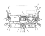
- FIG. 1 is a diagram illustrating a usage example of the head-up display according to the first embodiment.
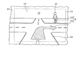
- FIG. 2 is a diagram illustrating a region of an image displayed by the head-up display according to the first embodiment.
- FIG. 3 is a diagram illustrating an example of an image displayed by the head-up display according to the first embodiment.
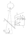
- FIG. 4 is a diagram illustrating a configuration of the head-up display according to the first embodiment.
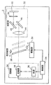
- FIG. 5 is a block diagram illustrating a functional configuration of the head-up display according to the first embodiment.
- FIG. 8 is a cross-sectional view corresponding to FIG. 7 of the Fresnel lens according to the first modification of the first embodiment.
- FIG. 9 is a cross-sectional view corresponding to FIG. 7 of the Fresnel lens according to the second modification of the first embodiment.
- FIG. 10 is a plan view of a Fresnel lens according to the third modification of the first embodiment when viewed from the direction of the optical axis.
- FIG. 11 is a cross-sectional view corresponding to FIG. 7 of the Fresnel lens according to the second embodiment.
- FIG. 12 is a cross-sectional view corresponding to FIG. 7 of the Fresnel lens according to the first modification of the second embodiment.
- a Fresnel lens is used for an optical system of an image system (for example, an eyepiece optical system).
- an image system for example, an eyepiece optical system.
- concentric stray light is generated due to scattered light and reflected light in the step shape of the Fresnel lens, there is a problem that the stray light is superimposed on the image and the image quality is deteriorated.
- the head-up display emits light constituting an image toward an eye box that is in a predetermined range in which an observer's eyes are assumed to exist.
- a head-up display including an optical system, the optical system being an uneven surface formed concentrically with the optical axis as a center, a condensing surface for condensing incident light toward the focus, and a focus Including a Fresnel lens that has a serrated irregular surface with a saw-tooth cross section formed by alternately arranging wall surfaces that are not condensed, and the wall surface reflects light that hits the wall surface in a direction that travels outside the range of the eye box Is inclined with respect to the optical axis of the Fresnel lens.
- the incident light reflected on the wall surface that is not focused toward the focal point out of the incident light is emitted in a direction that goes out of the range of the eye box, so that it is prevented from being viewed by the observer. be able to.
- the incident light which is not reflected by the wall surface among incident light is radiate
- the second wall surface arranged outside the first wall surface may be formed with a larger inclination with respect to the optical axis than the first wall surface.
- a head-up display includes a head-up including an optical system that emits light constituting an image toward an eye box that is in a predetermined range in which an observer's eyes are assumed to exist.
- the optical system is a concavo-convex surface formed concentrically around the optical axis, and a condensing surface that condenses incident light at the focal point and a wall surface that does not condense toward the focal point alternately Including a Fresnel lens having a serrated uneven surface, and the wall surface is inclined with respect to the optical axis of the Fresnel lens so that incident light on the Fresnel lens does not directly hit the wall surface.
- the condensing surface and the wall surface may be arranged so as to overlap each other when viewed from the optical axis.
- the optical system further includes a light source that emits light, a scanning unit that scans light from the light source, and a screen on which an image is formed by transmission of light from the scanning unit.
- a virtual image of the generated image may be displayed in space.
- FIG. 1 is a diagram illustrating a usage example of the head-up display 2 according to the first embodiment.
- FIG. 2 is a diagram showing a region 11 of the image 8 displayed by the head-up display 2 according to the first embodiment.
- FIG. 3 is a diagram illustrating an example of the image 8 displayed by the head-up display 2 according to the first embodiment.
- the head-up display 2 according to Embodiment 1 is a head-up display for a vehicle, for example, and is arranged inside a dashboard 6 of an automobile 4 (an example of a vehicle).
- laser light an example of light
- the laser light is reflected toward the driver 12 by the windshield 10.
- the driver 12 can see the image 8 that is a virtual image superimposed on the scenery 14 in front of the windshield 10. That is, the head-up display 2 displays (projects) the image 8 that is a virtual image in the space 16 in front of the windshield 10.
- the image 8 displayed by the head-up display 2 includes a vertical image 18 and a depth image 20.
- the vertical image 18 is a virtual image displayed in the vertical direction (vertical direction in FIG. 1) in the space 16 in front of the windshield 10.
- the vertical image 18 is, for example, a vertically long substantially oval mark, and is displayed superimposed on the pedestrian 22 existing in front of the automobile 4. As a result, the driver 12 can easily notice the presence of the pedestrian 22.
- the depth image 20 is a virtual image displayed in the depth direction (left-right direction in FIG. 1) that is a direction intersecting the vertical direction in the space 16 in front of the windshield 10.
- the depth image 20 is, for example, an arrow for guiding a travel route to the destination (in the example shown in FIG. 3, an arrow for instructing to turn right at the intersection), and the road 24 existing in front of the automobile 4. Is displayed superimposed on.
- the driver 12 can easily know the travel route to the destination.
- FIG. 4 is a diagram illustrating a configuration of the head-up display 2 according to the first embodiment.
- FIG. 5 is a block diagram illustrating a functional configuration of the head-up display 2 according to the first embodiment.
- the head-up display 2 includes a projection unit 26, a movable screen 28, a drive unit 30, a projection unit 32 (an example of an optical system), and a control unit 34.
- the projection unit 26 includes a light source 36 and a scanning unit 38.
- the light source 36 includes a red laser diode that emits red component (R) laser light, a green laser diode that emits green component (G) laser light, and a blue laser diode that emits blue component (B) laser light. And have.
- the red component laser beam, the green component laser beam, and the blue component laser beam emitted from the light source 36 are combined by, for example, a dichroic mirror (not shown) and then enter the scanning unit 38.
- the scanning unit 38 includes, for example, a MEMS (Micro Electro Mechanical Systems) mirror.
- the scanning unit 38 performs two-dimensional raster scanning of the laser beam from the light source 36 toward the movable screen 28 by reflecting the incident laser beam in a direction corresponding to its own deflection angle.
- the scanning unit 38 performs raster scanning of laser light in a direction from one end to the other end of the movable screen 28.
- the movable screen 28 is a translucent (for example, translucent) rectangular screen. As shown in FIG. 5, the movable screen 28 moves in the direction away from the scanning unit 38 (the direction indicated by the arrow X in FIG. 5 (X direction)) and the scanning unit 38 on the optical path of the laser light from the scanning unit 38. It is arranged so as to be able to reciprocate in the approaching direction (direction indicated by arrow Y in FIG. 5 (Y direction)). The movable screen 28 reciprocates in a posture inclined with respect to the moving direction (X direction and Y direction) of the movable screen 28.
- the laser beam from the scanning unit 38 is raster-scanned toward the movable screen 28, whereby an image is formed on the movable screen 28.
- the laser beam from the scanning unit 38 is raster-scanned toward the movable screen 28, whereby another image is formed on the movable screen 28.
- a fixed screen may be used instead of the movable screen 28.
- the drive unit 30 is composed of an actuator, for example.
- the drive unit 30 reciprocates (vibrates) the movable screen 28 in the X direction and the Y direction at a constant frequency (for example, 60 Hz) and a constant amplitude (for example, 1 mm) based on the drive signal from the control unit 34.
- the drive unit 30 reciprocates the movable screen 28 so that the time during which the movable screen 28 moves in the X direction (or Y direction) is, for example, 25 msec or less based on the drive signal from the control unit 34.
- the projection unit 32 includes a magnifying lens 44, a first reflecting plate 46, a second reflecting plate 48, a Fresnel lens 50, and the windshield 10.
- the magnifying lens 44 is disposed on the optical path of the laser beam that has passed through the movable screen 28.
- the magnifying lens 44 magnifies the image formed on the movable screen 28.
- the first reflecting plate 46 and the second reflecting plate 48 are arranged on the optical path of the laser light from the magnifying lens 44 and reflect the laser light from the magnifying lens 44 toward the windshield 10. Thereby, the first reflecting plate 46 and the second reflecting plate 48 project the image magnified by the magnifying lens 44 toward the windshield 10 via the Fresnel lens 50.
- the Fresnel lens 50 adjusts and projects to a size corresponding to the eye box 80 on the windshield 10 by narrowing the spread angle of the image magnified and spread by the magnifying lens 44.
- the eye box 80 is a predetermined range in which the eyes of the driver 12 (observer) are assumed to exist.
- the windshield 10 is disposed on the optical path of the laser light from the Fresnel lens 50, and reflects the laser light from the Fresnel lens 50 toward the eye box 80. Thereby, when a predetermined image is formed on the movable screen 28, the vertical image 18 that is a virtual image of the predetermined image is displayed in the space 16 in front of the windshield 10.
- the control unit 34 has a function of outputting a drive signal to the drive unit 30, a function of controlling a drive current supplied to the light source 36, and a function of controlling a deflection angle of the scanning unit 38.
- the control unit 34 is configured by, for example, a CPU (Central Processing Unit) or a processor, and executes the above functions by reading out a computer program stored in a memory (not shown) and executing it.
- a CPU Central Processing Unit
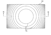
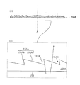
- FIG. 6 is a plan view of the Fresnel lens according to Embodiment 1 as viewed from the direction of the optical axis.
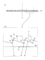
- 7 is a cross-sectional view taken along the line VII-VII in FIG. 7A is a diagram showing the entire cross-sectional view of the Fresnel lens 50, and
- FIG. 7B is an enlarged view of a part of the cross-sectional view of the Fresnel lens 50.
- the Fresnel lens 50 is a rectangular plate-like member, and includes a flat surface 52 disposed on the light incident side, and a sawtooth uneven surface 51 disposed on the light emission side.
- the surface of the Fresnel lens 50 opposite to the uneven surface 51 is a flat surface 52.
- the Fresnel lens 50 is made of a resin such as acrylic.
- the uneven surface 51 of the Fresnel lens 50 is formed by alternately arranging first surfaces 51 a that are inclined with respect to the optical axis A and second surfaces 51 b that are substantially parallel to the optical axis A. Further, as shown in FIG. 6, the uneven surface 51 is formed concentrically.
- the first surface 51a is a condensing surface that condenses incident light on the Fresnel lens 50 toward a predetermined focal point. That is, the first surface 51a refracts incident light on the Fresnel lens 50 toward a predetermined focal point.
- the first surface 51a is formed in a plurality of concentric circles, and the first surface 51a disposed on the inner side (on the optical axis A side) of the plurality of first surfaces 51a has a larger inclination angle to the optical axis A. Become.
- the second surface 51b is a wall surface that does not collect light toward a predetermined focal point.
- the 2nd surface 51b is a wall surface formed in order to offset the 1st surface 51a which is a condensing surface, in order to make the thickness of a convex lens thin.
- the first surface 51a is disposed outside the second surface 51b. Surface.
- the Fresnel lens 50 has a light shielding mask 53 in a part of the first surface 51a adjacent to the second surface 51b.
- the light-shielding mask 53 is a coating film formed by spraying a paint having a light-shielding property by ink jet printing or the like.
- the light shielding mask 53 is formed in a part of the first surface 51a on the inner side (optical axis A side) and a part of the outer side.
- a plurality of light shielding masks 53 are formed concentrically when viewed from the direction of the optical axis A.
- the incident light a1 and a2 reflected by the second surface 51b substantially parallel to the optical axis A hits the light shielding mask 53, and therefore the incident light a1 and a2 Can be prevented from being emitted from the Fresnel lens 50 to the outside.
- the incident light a3 that is not reflected by the second surface 51b among the incident light does not strike the light shielding mask 53, and therefore can be emitted outward from the Fresnel lens 50. For this reason, generation
- the light shielding mask 53 is provided on the uneven surface 51 side.
- the configuration is not limited to this configuration, and the light shielding mask 53 may be provided on the flat surface 52 side. .
- FIG. 8 is a cross-sectional view corresponding to FIG. 7 of the Fresnel lens according to the first modification of the first embodiment.
- the configuration excluding the light shielding mask 53A of the Fresnel lens 50A according to the first modification of the first embodiment is the same as the configuration excluding the light shielding mask 53 of the Fresnel lens 50 according to the first embodiment.
- the Fresnel lens 50A differs from the Fresnel lens 50 of the first embodiment in that the surface on which the light shielding mask 53A is formed is the incident-side flat surface 52. That is, the light shielding mask 53A is formed on the plane 52 at a position facing the second surface 51b.
- the light shielding mask 53A has incident light a4 and a5 about to enter the Fresnel lens 50A at an angle reflected by the second surface 51b in the region of the plane 52. It is formed in a region that prevents incidence on the Fresnel lens 50A.
- the light shielding mask 53A is not formed in a region of the plane 52 where the incident light a6 that is about to be incident at an angle that is not reflected by the second surface 51b is incident on the Fresnel lens 50A.
- the path of light when the incident lights a4 and a5 are not shielded by the light shielding mask 53A is indicated by a two-dot chain line arrow.
- the region where the light shielding mask 53A is formed can be obtained from the angle of incident light, the angle at which the incident light is refracted in the plane 52, and the shape of the Fresnel lens 50A.
- a plurality of light shielding masks 53A are concentrically formed when viewed from the direction of the optical axis A, as in the first embodiment.
- FIG. 9 is a cross-sectional view corresponding to FIG. 7 of the Fresnel lens 50B according to the second modification of the first embodiment.
- the Fresnel lens 50B has the same configuration as that of the Fresnel lens 50 according to Embodiment 1 except for the light shielding mask 53.
- the light shielding mask 53 has a configuration provided on the surface of the Fresnel lenses 50 and 50A. It is good also as a structure which employ
- the Fresnel lens unit 70 includes a Fresnel lens 50 ⁇ / b> B in which a light shielding mask is not formed and a transparent plate-like member 60.
- the plate-like member 60 is a transparent plate-like member (substrate) disposed so as to face the Fresnel lens 50B, and a light shielding mask 61 is formed at a position facing the second surface 51b of the Fresnel lens 50B.
- the light shielding mask 61 is formed on the incident-side surface of the plate-like member 60, and among the incident-side surfaces of the plate-like member 60, the Fresnel lens 50 ⁇ / b> B. It is formed in a region where the light a7 and a8 reflected by the second surface 51b strike.
- the light shielding mask 61 is formed in a region that prevents the light a7 and a8 reflected by the second surface 51b of the Fresnel lens 50B from being emitted from the Fresnel lens unit 70.
- the light shielding mask 61 is not formed in a region of the incident-side surface of the plate-like member 60 where the light a9 emitted without being reflected by the second surface 51b hits.
- the region where the light shielding mask 61 is formed includes an angle of light incident on the Fresnel lens 50B, an angle at which the light is refracted on the plane 52, an angle at which the light is reflected on the second surface 51b, and the light. Can be determined from the angle at which the concavo-convex surface 51 is refracted and the shape of the Fresnel lens 50B.
- the light shielding mask 53 may have a shape as shown in FIG.
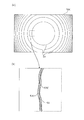
- FIG. 10 is a plan view of the Fresnel lens according to the third modification of the first embodiment when viewed from the direction of the optical axis.
- 10A is a plan view when the Fresnel lens 50C is viewed from the direction of the optical axis, and
- FIG. 10B is an enlarged view of a part of FIG. 610A.
- the end of the mask pattern of the light shielding mask 53C has a meandering shape.
- the mask pattern of the light shielding mask 53C formed in a circular shape has a shape in which the radially outer and inner end portions meander.
- the Fresnel lens 50 using the light shielding mask 53 according to the first embodiment incident light or outgoing light is shielded by the light shielding mask 53, so that light is diffracted at the edge portion of the mask pattern of the light shielding mask 53 and slight stray light is generated. appear. From the observer's point of view, the mask pattern appears to shine lightly.
- the direction in which the stray light is diffracted can be made different depending on the angle of the end, and the diffracted light is dispersed over a wide angle. Can do. For this reason, the diffracted light visually recognized by the observer can be reduced.
- the shape of the light shielding mask 53C described above may be applied to the light shielding masks 53A and 61 of the Fresnel lens 50A and the Fresnel lens unit 70 according to the first and second modifications of the first embodiment.
- the reflected light is not emitted from the second surface 51b that causes stray light.
- the light shielding masks 53, 53A and 61 for shielding light are formed, but the light shielding masks 53, 53A and 61 do not shield stray light.
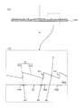
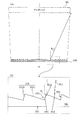
- FIG. 11 is a cross-sectional view corresponding to FIG. 7 of the Fresnel lens according to the second embodiment.
- the Fresnel lens 150 As shown in FIG. 11, the Fresnel lens 150 according to the second embodiment has a flat surface 152 on the light incident side and a serrated irregular surface 151 on the light emission side. That is, the surface of the Fresnel lens 150 opposite to the uneven surface 151 is a flat surface 152.
- the Fresnel lens 150 is made of a resin such as acrylic.
- the uneven surface 151 of the Fresnel lens 150 is formed concentrically.
- the first surface 151a is a condensing surface that condenses incident light on the Fresnel lens 50 toward a predetermined focal point. That is, the first surface 151a refracts incident light on the Fresnel lens 150 toward a predetermined focal point.
- a plurality of first surfaces 151a are formed concentrically, and the first surface 151a disposed on the inner side (on the optical axis A side) of the plurality of first surfaces 151a has a larger inclination angle to the optical axis A. Become.
- the second surface 151b is a wall surface that does not collect light toward a predetermined focal point.
- the second surface 151b is a wall surface formed by offsetting the first surface 151a, which is a condensing surface, in order to reduce the thickness of the convex lens.
- the first surface 151a is a surface that is disposed outside the second surface 151b. .
- the second surface 151b is formed so as to be inclined with respect to the optical axis A of the Fresnel lens 150 at an angle at which the light hitting the second surface 151b is reflected in the direction of traveling out of the range of the eye box 80.
- the second surface 151b is formed to be inclined with respect to the optical axis A so as to spread outward as it goes from the incident side to the emission side. That is, the first surface 151a and the second surface 151b are formed in regions that do not overlap each other when viewed from the direction of the optical axis A.
- the second wall surface disposed outside the first wall surface is formed with a larger inclination with respect to the optical axis than the first wall surface.
- the Fresnel lens 150 can be configured as follows.
- the horizontal width of the image 8 is 400 mm
- the horizontal width of the eyebox 80 is 130 mm think of.
- the horizontal width of the Fresnel lens 150 is 270 mm
- the incident angle ⁇ in to the Fresnel lens 150 is about ⁇ 4 degrees in the vicinity of the optical axis A of the Fresnel lens 150
- the horizontal end of the Fresnel lens 150 It will be 4-12 degrees.
- the inclination angle ⁇ s of the second surface 151 b of the Fresnel lens 150 is set to 4 degrees or more at the portion near the optical axis A of the Fresnel lens 150 and 12 degrees or more at the horizontal end of the Fresnel lens 150.
- the reflected light on the second surface 151b can be diverted out of the range of the eye box 80.
- the incident light a11 reflected by the second surface 151b as a wall surface that is not condensed toward the focal point travels outside the range of the eye box 80. Since it is emitted at (emission angle ⁇ o 1), it can be prevented from being visually recognized by the driver 12 as an observer.
- the incident light a12 that is not reflected by the second surface 151a out of the incident light is emitted in a direction (exit angle ⁇ o 2) that travels within the range of the eye box 80, so that it can be visually recognized by the driver 12. it can. For this reason, it can reduce effectively that the driver
- the first surface 151a and the second surface 151b are formed in regions that do not overlap with each other when viewed from the direction of the optical axis A. Not exclusively.
- FIG. 12 is a cross-sectional view corresponding to FIG. 7 of the Fresnel lens according to the first modification of the second embodiment.
- the first surface 151Aa and the second surface 151Ab are arranged so as to overlap each other when viewed in the optical axis direction as compared with the Fresnel lens 150 of the second embodiment. Is different. That is, the second surface 151Ab is formed to be inclined with respect to the optical axis A of the Fresnel lens 150A at an angle at which the incident light on the Fresnel lens 150A does not directly hit the wall surface.
- the present invention is not limited to this embodiment.
- the present invention is not limited to this. .
- the present invention is not limited thereto, and may be mounted on, for example, glasses configured as a wearable device.
- each component may be configured by dedicated hardware or may be realized by executing a software program suitable for each component.
- Each component may be realized by a program execution unit such as a CPU or a processor reading and executing a software program recorded on a recording medium such as a hard disk or a semiconductor memory.
- Each of the above devices is specifically realized by a computer system including a microprocessor, a ROM (Read Only Memory), a RAM (Read Access Memory), a hard disk unit, a display unit, a keyboard, a mouse, and the like. obtain.
- a computer program is stored in the RAM or the hard disk unit.
- Each device achieves its functions by the microprocessor operating according to the computer program.
- the computer program is configured by combining a plurality of instruction codes indicating instructions for the computer in order to achieve a predetermined function.
- a part or all of the constituent elements constituting each of the above devices may be constituted by one system LSI (Large Scale Integration).
- the system LSI is an ultra-multifunctional LSI manufactured by integrating a plurality of components on a single chip, and specifically, a computer system including a microprocessor, ROM, RAM, and the like. .
- a computer program is stored in the ROM.
- the system LSI achieves its functions by the microprocessor loading a computer program from the ROM to the RAM and performing operations such as operations in accordance with the loaded computer program.
- a part or all of the constituent elements constituting each of the above devices may be configured by an IC (Integrated Circuit) card that can be attached to and detached from each device or a single module.
- the IC card or module is a computer system that includes a microprocessor, ROM, RAM, and the like.
- the IC card or the module may include the super multifunctional LSI described above.
- the IC card or the module achieves its function by the microprocessor operating according to the computer program. This IC card or this module may have tamper resistance.
- the present invention may be realized by the method described above. Further, these methods may be realized by a computer program realized by a computer, or may be realized by a digital signal consisting of a computer program.
- the present invention also relates to a recording medium capable of reading a computer program or a digital signal, such as a flexible disk, hard disk, CD (Compact Disc) -ROM, MO (Magneto-Optical disc), DVD (Digital Versatile Disc), DVD. It may be realized by recording on a ROM, DVD-RAM, BD (Blu-ray (registered trademark) Disc), semiconductor memory or the like. Moreover, you may implement
- a computer program or a digital signal may be transmitted via an electric communication line, a wireless or wired communication line, a network represented by the Internet, a data broadcast, or the like.
- the present invention is also a computer system including a microprocessor and a memory.
- the memory stores a computer program, and the microprocessor may operate according to the computer program.
- program or digital signal may be recorded on a recording medium and transferred, or the program or digital signal may be transferred via a network or the like, and may be implemented by another independent computer system.
- the head-up display of the present invention can be applied to, for example, a vehicle-mounted head-up display.
- Second reflecting plate 50, 50A, 50B, 150, 150A Fresnel lens 51, 151 Uneven surface 51a, 151a, 151Aa First surface 51b, 151b, 151Ab Second Surface 52, 152 Plane 53, 53A, 61 Shading mask 60 Plate member 70 Fresnel lens unit 80 Eye box a1 to a6, a11, a12 Incident light a7 to a9 light
Landscapes
- Physics & Mathematics (AREA)
- Engineering & Computer Science (AREA)
- General Physics & Mathematics (AREA)
- Optics & Photonics (AREA)
- Chemical & Material Sciences (AREA)
- Combustion & Propulsion (AREA)
- Transportation (AREA)
- Mechanical Engineering (AREA)
- Instrument Panels (AREA)
Priority Applications (2)
| Application Number | Priority Date | Filing Date | Title |
|---|---|---|---|
| DE112016006259.1T DE112016006259T5 (de) | 2016-01-20 | 2016-12-02 | Head-up-display |
| US16/026,109 US10642032B2 (en) | 2016-01-20 | 2018-07-03 | Head-up display |
Applications Claiming Priority (2)
| Application Number | Priority Date | Filing Date | Title |
|---|---|---|---|
| JP2016-009292 | 2016-01-20 | ||
| JP2016009292A JP6628137B2 (ja) | 2016-01-20 | 2016-01-20 | ヘッドアップディスプレイ |
Related Child Applications (1)
| Application Number | Title | Priority Date | Filing Date |
|---|---|---|---|
| US16/026,109 Continuation US10642032B2 (en) | 2016-01-20 | 2018-07-03 | Head-up display |
Publications (1)
| Publication Number | Publication Date |
|---|---|
| WO2017125979A1 true WO2017125979A1 (ja) | 2017-07-27 |
Family
ID=59362168
Family Applications (1)
| Application Number | Title | Priority Date | Filing Date |
|---|---|---|---|
| PCT/JP2016/005048 Ceased WO2017125979A1 (ja) | 2016-01-20 | 2016-12-02 | ヘッドアップディスプレイ |
Country Status (4)
| Country | Link |
|---|---|
| US (1) | US10642032B2 (enExample) |
| JP (1) | JP6628137B2 (enExample) |
| DE (1) | DE112016006259T5 (enExample) |
| WO (1) | WO2017125979A1 (enExample) |
Cited By (2)
| Publication number | Priority date | Publication date | Assignee | Title |
|---|---|---|---|---|
| TWI651549B (zh) * | 2018-02-12 | 2019-02-21 | 玉晶光電股份有限公司 | 菲涅耳透鏡 |
| US10732327B2 (en) | 2018-02-12 | 2020-08-04 | Genius Electronic Optical Co., Ltd. | Fresnel lens |
Families Citing this family (3)
| Publication number | Priority date | Publication date | Assignee | Title |
|---|---|---|---|---|
| CN107632388B (zh) * | 2017-10-24 | 2024-04-02 | 歌尔光学科技有限公司 | 目镜及头戴显示设备 |
| CN110146994B (zh) * | 2019-05-21 | 2021-08-06 | 京东方科技集团股份有限公司 | 一种滤光结构、眼镜和显示面板 |
| CN112622767A (zh) | 2019-10-08 | 2021-04-09 | 松下知识产权经营株式会社 | 显示系统、以及具备该显示系统的电子后视镜系统 |
Citations (6)
| Publication number | Priority date | Publication date | Assignee | Title |
|---|---|---|---|---|
| JPH0875906A (ja) * | 1994-09-02 | 1996-03-22 | Casio Comput Co Ltd | フレネルレンズ |
| JPH09218465A (ja) * | 1996-02-09 | 1997-08-19 | Minolta Co Ltd | スクリーン装置 |
| JP2005084172A (ja) * | 2003-09-05 | 2005-03-31 | Calsonic Kansei Corp | 車両用表示器 |
| JP2013137442A (ja) * | 2011-12-28 | 2013-07-11 | Panasonic Corp | フレネルレンズ |
| JP2014191285A (ja) * | 2013-03-28 | 2014-10-06 | Shimadzu Corp | 背面投写型表示装置及びそれに用いられるフレネルレンズ |
| JP2015184432A (ja) * | 2014-03-24 | 2015-10-22 | アイシン・エィ・ダブリュ株式会社 | ヘッドアップディスプレイ装置 |
Family Cites Families (12)
| Publication number | Priority date | Publication date | Assignee | Title |
|---|---|---|---|---|
| JP4258353B2 (ja) * | 2003-10-31 | 2009-04-30 | コニカミノルタオプト株式会社 | 光学素子 |
| TWI294023B (en) * | 2006-03-17 | 2008-03-01 | Ind Tech Res Inst | Reflective illumination device |
| WO2007145118A1 (ja) * | 2006-06-13 | 2007-12-21 | Panasonic Corporation | 複合光学素子 |
| JP5147694B2 (ja) * | 2006-06-13 | 2013-02-20 | パナソニック株式会社 | 複合光学素子 |
| JP5393020B2 (ja) * | 2007-04-26 | 2014-01-22 | 株式会社リコー | 光ピックアップおよび光情報処理装置 |
| JP2009069457A (ja) * | 2007-09-13 | 2009-04-02 | Seiko Epson Corp | 光走査素子及び画像表示装置 |
| WO2012016047A1 (en) * | 2010-07-28 | 2012-02-02 | Flex Lighting Ii, Llc | Light emitting device with optical redundancy |
| JP2014043205A (ja) | 2012-08-28 | 2014-03-13 | Dainippon Printing Co Ltd | 車両用映像表示システム |
| DE102013014277A1 (de) * | 2013-08-27 | 2015-03-05 | Rosenberger Hochfrequenztechnik Gmbh & Co. Kg | Vorrichtung zum Einkoppeln von Pumplicht in eine Faser und Verfahren zum Herstellen einer solchen Vorrichtung |
| JP2015161732A (ja) * | 2014-02-26 | 2015-09-07 | 矢崎総業株式会社 | 表示光投影用光学デバイス |
| US10544918B2 (en) * | 2014-10-23 | 2020-01-28 | Daicel Corporation | Fresnel lens and optical device provided with same |
| US9928769B2 (en) * | 2015-09-29 | 2018-03-27 | Panasonic Intellectual Property Management Co., Ltd. | Head-up display and vehicle equipped with head-up display |
-
2016
- 2016-01-20 JP JP2016009292A patent/JP6628137B2/ja active Active
- 2016-12-02 DE DE112016006259.1T patent/DE112016006259T5/de active Pending
- 2016-12-02 WO PCT/JP2016/005048 patent/WO2017125979A1/ja not_active Ceased
-
2018
- 2018-07-03 US US16/026,109 patent/US10642032B2/en active Active
Patent Citations (6)
| Publication number | Priority date | Publication date | Assignee | Title |
|---|---|---|---|---|
| JPH0875906A (ja) * | 1994-09-02 | 1996-03-22 | Casio Comput Co Ltd | フレネルレンズ |
| JPH09218465A (ja) * | 1996-02-09 | 1997-08-19 | Minolta Co Ltd | スクリーン装置 |
| JP2005084172A (ja) * | 2003-09-05 | 2005-03-31 | Calsonic Kansei Corp | 車両用表示器 |
| JP2013137442A (ja) * | 2011-12-28 | 2013-07-11 | Panasonic Corp | フレネルレンズ |
| JP2014191285A (ja) * | 2013-03-28 | 2014-10-06 | Shimadzu Corp | 背面投写型表示装置及びそれに用いられるフレネルレンズ |
| JP2015184432A (ja) * | 2014-03-24 | 2015-10-22 | アイシン・エィ・ダブリュ株式会社 | ヘッドアップディスプレイ装置 |
Cited By (2)
| Publication number | Priority date | Publication date | Assignee | Title |
|---|---|---|---|---|
| TWI651549B (zh) * | 2018-02-12 | 2019-02-21 | 玉晶光電股份有限公司 | 菲涅耳透鏡 |
| US10732327B2 (en) | 2018-02-12 | 2020-08-04 | Genius Electronic Optical Co., Ltd. | Fresnel lens |
Also Published As
| Publication number | Publication date |
|---|---|
| JP2017129751A (ja) | 2017-07-27 |
| JP6628137B2 (ja) | 2020-01-08 |
| US20180314064A1 (en) | 2018-11-01 |
| DE112016006259T5 (de) | 2018-11-08 |
| US10642032B2 (en) | 2020-05-05 |
Similar Documents
| Publication | Publication Date | Title |
|---|---|---|
| JP6610887B2 (ja) | フレネルレンズ及びヘッドアップディスプレイ | |
| US10642032B2 (en) | Head-up display | |
| JP7065383B2 (ja) | 表示システム、情報提示システム、表示システムの制御方法、プログラム、及び移動体 | |
| JP6098375B2 (ja) | ヘッドアップディスプレイ装置 | |
| CN103257449B (zh) | 光扫描装置以及图像显示装置 | |
| JP6512449B2 (ja) | 表示装置 | |
| JP6375825B2 (ja) | ヘッドアップディスプレイ装置 | |
| JP6056680B2 (ja) | ヘッドアップディスプレイ装置 | |
| JP6489371B2 (ja) | 表示装置 | |
| JP6451686B2 (ja) | ヘッドアップディスプレイ装置 | |
| JP2015022158A (ja) | 光走査装置および画像表示装置 | |
| WO2017125974A1 (ja) | 表示装置 | |
| WO2018225309A1 (ja) | 虚像表示装置、中間像形成部および画像表示光生成ユニット | |
| US10432899B2 (en) | Image display device | |
| JP2017067944A (ja) | 表示画像作成装置および画像表示装置 | |
| CN109116557A (zh) | 平视显示装置及行驶装置 | |
| JP6710017B2 (ja) | 画像表示装置 | |
| JP7367525B2 (ja) | 表示装置、表示システムおよび移動体 | |
| JP6820502B2 (ja) | 画像表示装置 | |
| JP6726883B2 (ja) | 表示システム、移動体、及び表示システムの制御方法 | |
| WO2020189191A1 (en) | Projector, display system, and mobile object | |
| JP2018040842A (ja) | ヘッドアップディスプレイ装置 | |
| WO2018030203A1 (ja) | 表示装置 | |
| JP2018194820A (ja) | 虚像形成装置及び移動体 | |
| US10502953B2 (en) | Display device, and mobile body having same |
Legal Events
| Date | Code | Title | Description |
|---|---|---|---|
| 121 | Ep: the epo has been informed by wipo that ep was designated in this application |
Ref document number: 16886224 Country of ref document: EP Kind code of ref document: A1 |
|
| 122 | Ep: pct application non-entry in european phase |
Ref document number: 16886224 Country of ref document: EP Kind code of ref document: A1 |