WO2017125979A1 - Head-up display - Google Patents
Head-up display Download PDFInfo
- Publication number
- WO2017125979A1 WO2017125979A1 PCT/JP2016/005048 JP2016005048W WO2017125979A1 WO 2017125979 A1 WO2017125979 A1 WO 2017125979A1 JP 2016005048 W JP2016005048 W JP 2016005048W WO 2017125979 A1 WO2017125979 A1 WO 2017125979A1
- Authority
- WO
- WIPO (PCT)
- Prior art keywords
- light
- fresnel lens
- head
- wall surface
- optical axis
- Prior art date
Links
- 230000003287 optical effect Effects 0.000 claims abstract description 67
- 230000005540 biological transmission Effects 0.000 claims description 2
- 239000012141 concentrate Substances 0.000 abstract 2
- 238000012986 modification Methods 0.000 description 23
- 230000004048 modification Effects 0.000 description 23
- 238000004590 computer program Methods 0.000 description 14
- 238000010586 diagram Methods 0.000 description 11
- 230000006870 function Effects 0.000 description 8
- 239000000470 constituent Substances 0.000 description 7
- 230000006866 deterioration Effects 0.000 description 3
- 230000001788 irregular Effects 0.000 description 3
- 238000000034 method Methods 0.000 description 3
- NIXOWILDQLNWCW-UHFFFAOYSA-N acrylic acid group Chemical group C(C=C)(=O)O NIXOWILDQLNWCW-UHFFFAOYSA-N 0.000 description 2
- 230000015556 catabolic process Effects 0.000 description 2
- 238000004891 communication Methods 0.000 description 2
- 238000006731 degradation reaction Methods 0.000 description 2
- 230000000694 effects Effects 0.000 description 2
- 239000011521 glass Substances 0.000 description 2
- 239000011347 resin Substances 0.000 description 2
- 229920005989 resin Polymers 0.000 description 2
- 239000004065 semiconductor Substances 0.000 description 2
- 230000003190 augmentative effect Effects 0.000 description 1
- 239000011248 coating agent Substances 0.000 description 1
- 238000000576 coating method Methods 0.000 description 1
- 210000003128 head Anatomy 0.000 description 1
- 238000007641 inkjet printing Methods 0.000 description 1
- 230000010354 integration Effects 0.000 description 1
- 238000004519 manufacturing process Methods 0.000 description 1
- 239000000463 material Substances 0.000 description 1
- 239000003973 paint Substances 0.000 description 1
- 238000005507 spraying Methods 0.000 description 1
- 239000000758 substrate Substances 0.000 description 1
Images


Classifications
-
- G—PHYSICS
- G02—OPTICS
- G02B—OPTICAL ELEMENTS, SYSTEMS OR APPARATUS
- G02B27/00—Optical systems or apparatus not provided for by any of the groups G02B1/00 - G02B26/00, G02B30/00
- G02B27/01—Head-up displays
- G02B27/0101—Head-up displays characterised by optical features
-
- B—PERFORMING OPERATIONS; TRANSPORTING
- B60—VEHICLES IN GENERAL
- B60K—ARRANGEMENT OR MOUNTING OF PROPULSION UNITS OR OF TRANSMISSIONS IN VEHICLES; ARRANGEMENT OR MOUNTING OF PLURAL DIVERSE PRIME-MOVERS IN VEHICLES; AUXILIARY DRIVES FOR VEHICLES; INSTRUMENTATION OR DASHBOARDS FOR VEHICLES; ARRANGEMENTS IN CONNECTION WITH COOLING, AIR INTAKE, GAS EXHAUST OR FUEL SUPPLY OF PROPULSION UNITS IN VEHICLES
- B60K35/00—Arrangement of adaptations of instruments
-
- B60K35/23—
-
- G—PHYSICS
- G02—OPTICS
- G02B—OPTICAL ELEMENTS, SYSTEMS OR APPARATUS
- G02B3/00—Simple or compound lenses
- G02B3/02—Simple or compound lenses with non-spherical faces
- G02B3/08—Simple or compound lenses with non-spherical faces with discontinuous faces, e.g. Fresnel lens
-
- G—PHYSICS
- G02—OPTICS
- G02B—OPTICAL ELEMENTS, SYSTEMS OR APPARATUS
- G02B30/00—Optical systems or apparatus for producing three-dimensional [3D] effects, e.g. stereoscopic images
- G02B30/50—Optical systems or apparatus for producing three-dimensional [3D] effects, e.g. stereoscopic images the image being built up from image elements distributed over a 3D volume, e.g. voxels
- G02B30/54—Optical systems or apparatus for producing three-dimensional [3D] effects, e.g. stereoscopic images the image being built up from image elements distributed over a 3D volume, e.g. voxels the 3D volume being generated by moving a 2D surface, e.g. by vibrating or rotating the 2D surface
-
- G—PHYSICS
- G02—OPTICS
- G02B—OPTICAL ELEMENTS, SYSTEMS OR APPARATUS
- G02B5/00—Optical elements other than lenses
- G02B5/003—Light absorbing elements
-
- B60K2360/23—
-
- B60K2360/334—
-
- B—PERFORMING OPERATIONS; TRANSPORTING
- B60—VEHICLES IN GENERAL
- B60Y—INDEXING SCHEME RELATING TO ASPECTS CROSS-CUTTING VEHICLE TECHNOLOGY
- B60Y2400/00—Special features of vehicle units
- B60Y2400/92—Driver displays
-
- G—PHYSICS
- G02—OPTICS
- G02B—OPTICAL ELEMENTS, SYSTEMS OR APPARATUS
- G02B27/00—Optical systems or apparatus not provided for by any of the groups G02B1/00 - G02B26/00, G02B30/00
- G02B27/01—Head-up displays
- G02B27/0101—Head-up displays characterised by optical features
- G02B2027/011—Head-up displays characterised by optical features comprising device for correcting geometrical aberrations, distortion
-
- G—PHYSICS
- G02—OPTICS
- G02B—OPTICAL ELEMENTS, SYSTEMS OR APPARATUS
- G02B27/00—Optical systems or apparatus not provided for by any of the groups G02B1/00 - G02B26/00, G02B30/00
- G02B27/01—Head-up displays
- G02B27/0101—Head-up displays characterised by optical features
- G02B2027/0118—Head-up displays characterised by optical features comprising devices for improving the contrast of the display / brillance control visibility
-
- G—PHYSICS
- G02—OPTICS
- G02B—OPTICAL ELEMENTS, SYSTEMS OR APPARATUS
- G02B27/00—Optical systems or apparatus not provided for by any of the groups G02B1/00 - G02B26/00, G02B30/00
- G02B27/01—Head-up displays
- G02B27/0101—Head-up displays characterised by optical features
- G02B2027/0127—Head-up displays characterised by optical features comprising devices increasing the depth of field
-
- G—PHYSICS
- G02—OPTICS
- G02B—OPTICAL ELEMENTS, SYSTEMS OR APPARATUS
- G02B27/00—Optical systems or apparatus not provided for by any of the groups G02B1/00 - G02B26/00, G02B30/00
- G02B27/01—Head-up displays
- G02B27/0101—Head-up displays characterised by optical features
- G02B2027/0132—Head-up displays characterised by optical features comprising binocular systems
- G02B2027/0136—Head-up displays characterised by optical features comprising binocular systems with a single image source for both eyes
-
- G—PHYSICS
- G02—OPTICS
- G02B—OPTICAL ELEMENTS, SYSTEMS OR APPARATUS
- G02B27/00—Optical systems or apparatus not provided for by any of the groups G02B1/00 - G02B26/00, G02B30/00
- G02B27/01—Head-up displays
- G02B27/0179—Display position adjusting means not related to the information to be displayed
- G02B2027/0185—Displaying image at variable distance
Landscapes
- Physics & Mathematics (AREA)
- General Physics & Mathematics (AREA)
- Optics & Photonics (AREA)
- Engineering & Computer Science (AREA)
- Chemical & Material Sciences (AREA)
- Combustion & Propulsion (AREA)
- Transportation (AREA)
- Mechanical Engineering (AREA)
- Instrument Panels (AREA)
Abstract
A head-up display according to the present invention is provided with an optical system that emits light toward an eye box (80), said light forming a projected image, said eye box (80) being a prescribed range in which an observer's eyes are assumed to be. The optical system includes a Fresnel lens (150) that has, on the exit side thereof, a jagged surface with a sawtooth-shaped cross-section, said jagged surface being concentrically formed with an optical axis (A) at the center thereof and being formed with first surfaces (151a) and second surfaces (151b) in an alternating arrangement, said first surfaces (151a) acting as light-concentrating surfaces that concentrate incident light toward a focal point, said second surfaces (151b) acting as wall surfaces that do not concentrate light toward a focal point. The second surfaces (151b) are formed at a slant with respect to the optical axis (A) of the Fresnel lens (150), at such an angle that light hitting the second surfaces (151b) is reflected in directions leading out of the range of the eye box (80).
Description
本発明は、ヘッドアップディスプレイに関する。
The present invention relates to a head-up display.
画像を表示するための表示装置として、例えば車両用のヘッドアップディスプレイ(HUD)が知られている(例えば、特許文献1参照)。このヘッドアップディスプレイは、いわゆるAR(Augmented Reality)を用いたものであり、可動スクリーンに形成された画像の虚像を車両のウインドシールド(フロントガラス)の前方の空間に表示する。これにより、運転者は、ウインドシールドの前方の景色上に、運転に関する情報(例えばカーナビゲーション情報等)を重ね合わせて見ることができる。
As a display device for displaying an image, for example, a head-up display (HUD) for a vehicle is known (for example, see Patent Document 1). This head-up display uses so-called AR (Augmented Reality), and displays a virtual image of an image formed on a movable screen in a space in front of a windshield (front glass) of a vehicle. As a result, the driver can superimpose driving information (for example, car navigation information) on the scenery in front of the windshield.
本発明は、画質の劣化を低減できるヘッドアップディスプレイを提供する。
The present invention provides a head-up display capable of reducing image quality degradation.
本発明の一態様に係るヘッドアップディスプレイは、観察者の眼が存在すると想定された所定の範囲であるアイボックスに向けて映像を構成する光を放出する光学系を備えるヘッドアップディスプレイであって、光学系は、光軸を中心として同心円状に形成される凹凸面であって、入射光を焦点に向けて集光する集光面と、焦点に向けて集光させない壁面とが交互に配置されて形成される、断面が鋸歯状の凹凸面を有するフレネルレンズを含み、壁面は、壁面に当たった光が、アイボックスの範囲外に進む向きに反射する角度で、フレネルレンズの光軸に対して傾いて形成されている。
A head-up display according to an aspect of the present invention is a head-up display including an optical system that emits light constituting an image toward an eye box that is in a predetermined range in which an observer's eyes are assumed to exist. The optical system is a concavo-convex surface formed concentrically around the optical axis, and a condensing surface that condenses incident light toward the focal point and a wall surface that does not condense toward the focal point are alternately arranged. The wall surface includes an Fresnel lens having a serrated uneven surface, and the wall surface is at an angle at which the light hitting the wall surface is reflected in a direction to go out of the range of the eye box, on the optical axis of the Fresnel lens. It is inclined with respect to it.
本発明の別の一態様に係るヘッドアップディスプレイは、観察者の眼が存在すると想定された所定の範囲であるアイボックスに向けて映像を構成する光を放出する光学系を備えるヘッドアップディスプレイであって、光学系は、光軸を中心として同心円状に形成される凹凸面であって、入射光を焦点に集光する集光面と、焦点に向けて集光させない壁面とが交互に配置されて形成される、断面が鋸歯状の凹凸面を有するフレネルレンズを含み、壁面は、フレネルレンズへの入射光が壁面に直接当たらない角度で、フレネルレンズの光軸に対して傾いて形成されている。
A head-up display according to another aspect of the present invention is a head-up display including an optical system that emits light constituting an image toward an eye box that is in a predetermined range in which an eye of an observer is assumed to exist. The optical system is an uneven surface formed concentrically around the optical axis, and a condensing surface that condenses incident light at the focal point and a wall surface that does not condense toward the focal point are alternately arranged. The wall surface is formed to be inclined with respect to the optical axis of the Fresnel lens at an angle at which incident light on the Fresnel lens does not directly hit the wall surface. ing.
本発明のヘッドアップディスプレイは、画質の劣化を低減できる。
The head-up display of the present invention can reduce image quality degradation.
(本発明の基礎となった知見)
本発明者は、「背景技術」の欄において記載した技術に関し、以下の問題が生じることを見出した。 (Knowledge that became the basis of the present invention)
The inventor has found that the following problems occur with respect to the technique described in the “Background Art” column.
本発明者は、「背景技術」の欄において記載した技術に関し、以下の問題が生じることを見出した。 (Knowledge that became the basis of the present invention)
The inventor has found that the following problems occur with respect to the technique described in the “Background Art” column.
特許文献1のヘッドアップディスプレイでは、映像系の光学系(例えば接眼光学系)にフレネルレンズが用いられている。特許文献1のヘッドアップディスプレイでは、フレネルレンズの段差形状において散乱光及び反射光のために同心円状の迷光が発生するため、当該迷光が画像に重畳し、画質が劣化するという問題がある。
In the head-up display of Patent Document 1, a Fresnel lens is used for an optical system of an image system (for example, an eyepiece optical system). In the head-up display of Patent Document 1, since concentric stray light is generated due to scattered light and reflected light in the step shape of the Fresnel lens, there is a problem that the stray light is superimposed on the image and the image quality is deteriorated.
このような問題を解決するために、本発明の一態様に係るヘッドアップディスプレイは、観察者の眼が存在すると想定された所定の範囲であるアイボックスに向けて映像を構成する光を放出する光学系を備えるヘッドアップディスプレイであって、光学系は、光軸を中心として同心円状に形成される凹凸面であって、入射光を焦点に向けて集光する集光面と、焦点に向けて集光させない壁面とが交互に配置されて形成される、断面が鋸歯状の凹凸面を有するフレネルレンズを含み、壁面は、壁面に当たった光が、アイボックスの範囲外に進む向きに反射する角度で、フレネルレンズの光軸に対して傾いて形成されている。
In order to solve such a problem, the head-up display according to one embodiment of the present invention emits light constituting an image toward an eye box that is in a predetermined range in which an observer's eyes are assumed to exist. A head-up display including an optical system, the optical system being an uneven surface formed concentrically with the optical axis as a center, a condensing surface for condensing incident light toward the focus, and a focus Including a Fresnel lens that has a serrated irregular surface with a saw-tooth cross section formed by alternately arranging wall surfaces that are not condensed, and the wall surface reflects light that hits the wall surface in a direction that travels outside the range of the eye box Is inclined with respect to the optical axis of the Fresnel lens.
本態様によれば、入射光のうち、焦点に向けて集光させない壁面に反射された入射光は、アイボックスの範囲外に進む向きで出射されるため、観察者に視認されることを防ぐことができる。また、入射光のうち、壁面に反射されていない入射光はアイボックスの範囲内に進む向きで出射されるため、運転者に視認させることができる。このため、壁面に反射されることが原因となる迷光が運転者に視認されることを効果的に低減できる。よってヘッドアップディスプレイにより表示される画像の劣化を効果的に低減できる。
According to this aspect, the incident light reflected on the wall surface that is not focused toward the focal point out of the incident light is emitted in a direction that goes out of the range of the eye box, so that it is prevented from being viewed by the observer. be able to. Moreover, since the incident light which is not reflected by the wall surface among incident light is radiate | emitted in the direction which advances within the range of an eyebox, it can be made to be visually recognized by a driver | operator. For this reason, it can reduce effectively that the driver | operator visually recognizes the stray light caused by being reflected by the wall surface. Therefore, it is possible to effectively reduce the deterioration of the image displayed by the head-up display.
また、凹凸面を形成している複数の壁面のうち、第1壁面よりも外側に配置される第2壁面は、第1壁面よりも光軸に対する傾きが大きく形成されていてもよい。
Further, among the plurality of wall surfaces forming the irregular surface, the second wall surface arranged outside the first wall surface may be formed with a larger inclination with respect to the optical axis than the first wall surface.
また、本発明の別の一態様に係るヘッドアップディスプレイは、観察者の眼が存在すると想定された所定の範囲であるアイボックスに向けて映像を構成する光を放出する光学系を備えるヘッドアップディスプレイであって、光学系は、光軸を中心として同心円状に形成される凹凸面であって、入射光を焦点に集光する集光面と、焦点に向けて集光させない壁面とが交互に配置されて形成される、断面が鋸歯状の凹凸面を有するフレネルレンズを含み、壁面は、フレネルレンズへの入射光が壁面に直接当たらない角度でフレネルレンズの光軸に対して傾いて形成されている。
In addition, a head-up display according to another aspect of the present invention includes a head-up including an optical system that emits light constituting an image toward an eye box that is in a predetermined range in which an observer's eyes are assumed to exist. The optical system is a concavo-convex surface formed concentrically around the optical axis, and a condensing surface that condenses incident light at the focal point and a wall surface that does not condense toward the focal point alternately Including a Fresnel lens having a serrated uneven surface, and the wall surface is inclined with respect to the optical axis of the Fresnel lens so that incident light on the Fresnel lens does not directly hit the wall surface. Has been.
また、集光面と壁面とは、光軸からみて重なって配置されていてもよい。
Further, the condensing surface and the wall surface may be arranged so as to overlap each other when viewed from the optical axis.
また、さらに、光を出射する光源と、光源からの光を走査する走査部と、走査部からの光が透過することにより画像が形成されるスクリーンと、を備え、光学系は、スクリーンに形成された画像の虚像を空間に表示してもよい。
The optical system further includes a light source that emits light, a scanning unit that scans light from the light source, and a screen on which an image is formed by transmission of light from the scanning unit. A virtual image of the generated image may be displayed in space.
以下、実施の形態について、図面を参照しながら具体的に説明する。
Hereinafter, embodiments will be specifically described with reference to the drawings.
なお、以下で説明する実施の形態は、いずれも包括的又は具体的な例を示すものである。以下の実施の形態で示される数値、形状、材料、構成要素、構成要素の配置位置及び接続形態、ステップ、ステップの順序などは、一例であり、本発明を限定する主旨ではない。また、以下の実施の形態における構成要素のうち、最上位概念を示す独立請求項に記載されていない構成要素については、任意の構成要素として説明される。
Note that all of the embodiments described below show a comprehensive or specific example. The numerical values, shapes, materials, constituent elements, arrangement positions and connecting forms of the constituent elements, steps, order of steps, and the like shown in the following embodiments are merely examples, and are not intended to limit the present invention. In addition, among the constituent elements in the following embodiments, constituent elements that are not described in the independent claims indicating the highest concept are described as optional constituent elements.
(実施の形態1)
[1-1.ヘッドアップディスプレイの概略構成]
まず、図1~図3を参照しながら、実施の形態1に係るヘッドアップディスプレイ2の概略構成について説明する。図1は、実施の形態1に係るヘッドアップディスプレイ2の使用例を示す図である。図2は、実施の形態1に係るヘッドアップディスプレイ2により表示される画像8の領域11を示す図である。図3は、実施の形態1に係るヘッドアップディスプレイ2により表示される画像8の一例を示す図である。 (Embodiment 1)
[1-1. General configuration of head-up display]
First, a schematic configuration of the head-updisplay 2 according to the first embodiment will be described with reference to FIGS. 1 to 3. FIG. 1 is a diagram illustrating a usage example of the head-up display 2 according to the first embodiment. FIG. 2 is a diagram showing a region 11 of the image 8 displayed by the head-up display 2 according to the first embodiment. FIG. 3 is a diagram illustrating an example of the image 8 displayed by the head-up display 2 according to the first embodiment.
[1-1.ヘッドアップディスプレイの概略構成]
まず、図1~図3を参照しながら、実施の形態1に係るヘッドアップディスプレイ2の概略構成について説明する。図1は、実施の形態1に係るヘッドアップディスプレイ2の使用例を示す図である。図2は、実施の形態1に係るヘッドアップディスプレイ2により表示される画像8の領域11を示す図である。図3は、実施の形態1に係るヘッドアップディスプレイ2により表示される画像8の一例を示す図である。 (Embodiment 1)
[1-1. General configuration of head-up display]
First, a schematic configuration of the head-up
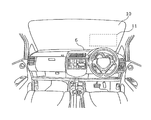
図1に示すように、実施の形態1に係るヘッドアップディスプレイ2は、例えば車両用のヘッドアップディスプレイであり、自動車4(車両の一例)のダッシュボード6の内部に配置されている。
As shown in FIG. 1, the head-up display 2 according to Embodiment 1 is a head-up display for a vehicle, for example, and is arranged inside a dashboard 6 of an automobile 4 (an example of a vehicle).
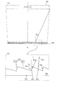
図1及び図2に示すように、ヘッドアップディスプレイ2では、虚像である画像8を表示するためのレーザ光(光の一例)を例えば自動車4のウインドシールド10の運転席寄り下側の領域11に向けて投射することにより、レーザ光をウインドシールド10で運転者12に向けて反射させる。これにより、図3に示すように、運転者12は、ウインドシールド10の前方の景色14上に、虚像である画像8を重ね合わせて見ることができる。すなわち、ヘッドアップディスプレイ2は、虚像である画像8をウインドシールド10の前方の空間16に表示(投影)する。
As shown in FIGS. 1 and 2, in the head-up display 2, laser light (an example of light) for displaying an image 8 that is a virtual image is, for example, an area 11 below the driver's seat of the windshield 10 of the automobile 4. By projecting toward the vehicle, the laser light is reflected toward the driver 12 by the windshield 10. Accordingly, as shown in FIG. 3, the driver 12 can see the image 8 that is a virtual image superimposed on the scenery 14 in front of the windshield 10. That is, the head-up display 2 displays (projects) the image 8 that is a virtual image in the space 16 in front of the windshield 10.
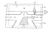
図3に示す例では、ヘッドアップディスプレイ2により表示される画像8は、鉛直画像18と奥行き画像20とを含んでいる。鉛直画像18は、ウインドシールド10の前方の空間16において鉛直方向(図1において上下方向)に表示される虚像である。鉛直画像18は、例えば縦長の略楕円形状のマークであり、自動車4の前方に存在する歩行者22に重畳して表示される。これにより、運転者12は、歩行者22の存在に容易に気付くことができる。
In the example shown in FIG. 3, the image 8 displayed by the head-up display 2 includes a vertical image 18 and a depth image 20. The vertical image 18 is a virtual image displayed in the vertical direction (vertical direction in FIG. 1) in the space 16 in front of the windshield 10. The vertical image 18 is, for example, a vertically long substantially oval mark, and is displayed superimposed on the pedestrian 22 existing in front of the automobile 4. As a result, the driver 12 can easily notice the presence of the pedestrian 22.
一方、奥行き画像20は、ウインドシールド10の前方の空間16において、鉛直方向と交差する方向である奥行き方向(図1において左右方向)に表示される虚像である。奥行き画像20は、例えば目的地までの走行経路を案内するための矢印(図3に示す例では、交差点を右折するように指示するための矢印)であり、自動車4の前方に存在する道路24に重畳して表示される。これにより、運転者12は、目的地までの走行経路を容易に知ることができる。
On the other hand, the depth image 20 is a virtual image displayed in the depth direction (left-right direction in FIG. 1) that is a direction intersecting the vertical direction in the space 16 in front of the windshield 10. The depth image 20 is, for example, an arrow for guiding a travel route to the destination (in the example shown in FIG. 3, an arrow for instructing to turn right at the intersection), and the road 24 existing in front of the automobile 4. Is displayed superimposed on. Thus, the driver 12 can easily know the travel route to the destination.
[1-2.ヘッドアップディスプレイの具体的構成]
次に、図4及び図5を参照しながら、実施の形態1に係るヘッドアップディスプレイ2の具体的構成について説明する。図4は、実施の形態1に係るヘッドアップディスプレイ2の構成を示す図である。図5は、実施の形態1に係るヘッドアップディスプレイ2の機能構成を示すブロック図である。 [1-2. Specific configuration of head-up display]
Next, a specific configuration of the head-updisplay 2 according to the first embodiment will be described with reference to FIGS. 4 and 5. FIG. 4 is a diagram illustrating a configuration of the head-up display 2 according to the first embodiment. FIG. 5 is a block diagram illustrating a functional configuration of the head-up display 2 according to the first embodiment.
次に、図4及び図5を参照しながら、実施の形態1に係るヘッドアップディスプレイ2の具体的構成について説明する。図4は、実施の形態1に係るヘッドアップディスプレイ2の構成を示す図である。図5は、実施の形態1に係るヘッドアップディスプレイ2の機能構成を示すブロック図である。 [1-2. Specific configuration of head-up display]
Next, a specific configuration of the head-up
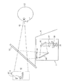
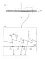
図4及び図5に示すように、ヘッドアップディスプレイ2は、投射部26、可動スクリーン28、駆動部30、投影部32(光学系の一例)及び制御部34を備えている。
4 and 5, the head-up display 2 includes a projection unit 26, a movable screen 28, a drive unit 30, a projection unit 32 (an example of an optical system), and a control unit 34.
投射部26は、光源36及び走査部38を有している。光源36は、赤色成分(R)のレーザ光を出射する赤色レーザダイオードと、緑色成分(G)のレーザ光を出射する緑色レーザダイオードと、青色成分(B)のレーザ光を出射する青色レーザダイオードとを有している。光源36から出射した赤色成分のレーザ光と緑色成分のレーザ光と青色成分のレーザ光とは、例えばダイクロイックミラー(図示せず)により合成された後に、走査部38に入射する。
The projection unit 26 includes a light source 36 and a scanning unit 38. The light source 36 includes a red laser diode that emits red component (R) laser light, a green laser diode that emits green component (G) laser light, and a blue laser diode that emits blue component (B) laser light. And have. The red component laser beam, the green component laser beam, and the blue component laser beam emitted from the light source 36 are combined by, for example, a dichroic mirror (not shown) and then enter the scanning unit 38.
走査部38は、例えばMEMS(Micro Electro Mechanical Systems)ミラーで構成されている。走査部38は、入射したレーザ光を自己の振れ角に応じた方向に反射することにより、光源36からのレーザ光を可動スクリーン28に向けて二次元的にラスタ走査する。走査部38は、例えば可動スクリーン28の両端の一端から他端に向かう方向にレーザ光をラスタ走査する。
The scanning unit 38 includes, for example, a MEMS (Micro Electro Mechanical Systems) mirror. The scanning unit 38 performs two-dimensional raster scanning of the laser beam from the light source 36 toward the movable screen 28 by reflecting the incident laser beam in a direction corresponding to its own deflection angle. For example, the scanning unit 38 performs raster scanning of laser light in a direction from one end to the other end of the movable screen 28.
可動スクリーン28は、透光性を有する(例えば半透明の)矩形状のスクリーンである。図5に示すように、可動スクリーン28は、走査部38からのレーザ光の光路上において、走査部38から離れる方向(図5中の矢印Xで示す方向(X方向))及び走査部38に近付く方向(図5中の矢印Yで示す方向(Y方向))に往復移動自在に配置されている。また、可動スクリーン28は、可動スクリーン28の移動方向(X方向及びY方向)に対して傾斜した姿勢で往復移動する。
The movable screen 28 is a translucent (for example, translucent) rectangular screen. As shown in FIG. 5, the movable screen 28 moves in the direction away from the scanning unit 38 (the direction indicated by the arrow X in FIG. 5 (X direction)) and the scanning unit 38 on the optical path of the laser light from the scanning unit 38. It is arranged so as to be able to reciprocate in the approaching direction (direction indicated by arrow Y in FIG. 5 (Y direction)). The movable screen 28 reciprocates in a posture inclined with respect to the moving direction (X direction and Y direction) of the movable screen 28.
可動スクリーン28がX方向に移動している状態で、走査部38からのレーザ光が可動スクリーン28に向けてラスタ走査されることにより、可動スクリーン28に画像が形成される。一方、可動スクリーン28がY方向に移動している状態で、走査部38からのレーザ光が可動スクリーン28に向けてラスタ走査されることにより、可動スクリーン28に別の画像が形成される。なお、可動スクリーン28の代わりに固定されたスクリーンを採用してもよい。
In a state where the movable screen 28 is moving in the X direction, the laser beam from the scanning unit 38 is raster-scanned toward the movable screen 28, whereby an image is formed on the movable screen 28. On the other hand, when the movable screen 28 is moving in the Y direction, the laser beam from the scanning unit 38 is raster-scanned toward the movable screen 28, whereby another image is formed on the movable screen 28. A fixed screen may be used instead of the movable screen 28.
駆動部30は、例えばアクチュエータで構成されている。駆動部30は、制御部34からの駆動信号に基づいて、一定の周波数(例えば60Hz)且つ一定の振幅(例えば1mm)で可動スクリーン28をX方向及びY方向に往復移動(振動)させる。なお、駆動部30は、制御部34からの駆動信号に基づいて、可動スクリーン28がX方向(又はY方向)に移動する間の時間が例えば25msec以下になるように、可動スクリーン28を往復移動させる。
The drive unit 30 is composed of an actuator, for example. The drive unit 30 reciprocates (vibrates) the movable screen 28 in the X direction and the Y direction at a constant frequency (for example, 60 Hz) and a constant amplitude (for example, 1 mm) based on the drive signal from the control unit 34. The drive unit 30 reciprocates the movable screen 28 so that the time during which the movable screen 28 moves in the X direction (or Y direction) is, for example, 25 msec or less based on the drive signal from the control unit 34. Let
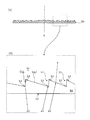
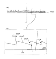
投影部32は、拡大レンズ44、第1の反射板46、第2の反射板48、フレネルレンズ50及びウインドシールド10を含んでいる。
The projection unit 32 includes a magnifying lens 44, a first reflecting plate 46, a second reflecting plate 48, a Fresnel lens 50, and the windshield 10.
拡大レンズ44は、可動スクリーン28を透過したレーザ光の光路上に配置されている。拡大レンズ44は、可動スクリーン28に形成された画像を拡大する。
The magnifying lens 44 is disposed on the optical path of the laser beam that has passed through the movable screen 28. The magnifying lens 44 magnifies the image formed on the movable screen 28.
第1の反射板46及び第2の反射板48は、拡大レンズ44からのレーザ光の光路上に配置され、拡大レンズ44からのレーザ光をウインドシールド10に向けて反射させる。これにより、第1の反射板46及び第2の反射板48は、拡大レンズ44により拡大された画像を、フレネルレンズ50を介してウインドシールド10に向けて投影する。
The first reflecting plate 46 and the second reflecting plate 48 are arranged on the optical path of the laser light from the magnifying lens 44 and reflect the laser light from the magnifying lens 44 toward the windshield 10. Thereby, the first reflecting plate 46 and the second reflecting plate 48 project the image magnified by the magnifying lens 44 toward the windshield 10 via the Fresnel lens 50.
フレネルレンズ50は、拡大レンズ44により拡大されて広がっている画像の広がり角度を狭めることで、ウインドシールド10上のアイボックス80に対応する範囲の大きさに調整して投影する。なお、アイボックス80とは、運転者12(観察者)の眼が存在すると想定された所定の範囲である。
The Fresnel lens 50 adjusts and projects to a size corresponding to the eye box 80 on the windshield 10 by narrowing the spread angle of the image magnified and spread by the magnifying lens 44. The eye box 80 is a predetermined range in which the eyes of the driver 12 (observer) are assumed to exist.
ウインドシールド10は、フレネルレンズ50からのレーザ光の光路上に配置され、フレネルレンズ50からのレーザ光をアイボックス80に向けて反射させる。これにより、可動スクリーン28に所定の画像が形成されている場合には、所定の画像の虚像である鉛直画像18がウインドシールド10の前方の空間16に表示される。
The windshield 10 is disposed on the optical path of the laser light from the Fresnel lens 50, and reflects the laser light from the Fresnel lens 50 toward the eye box 80. Thereby, when a predetermined image is formed on the movable screen 28, the vertical image 18 that is a virtual image of the predetermined image is displayed in the space 16 in front of the windshield 10.
制御部34は、駆動部30に駆動信号を出力する機能と、光源36に供給される駆動電流を制御する機能と、走査部38の振れ角を制御する機能とを有している。制御部34は、例えばCPU(Central Processing Unit)又はプロセッサ等で構成されており、メモリ(図示せず)に記憶されたコンピュータプログラムを読み出してそれを実行することにより上記各機能を実行する。
The control unit 34 has a function of outputting a drive signal to the drive unit 30, a function of controlling a drive current supplied to the light source 36, and a function of controlling a deflection angle of the scanning unit 38. The control unit 34 is configured by, for example, a CPU (Central Processing Unit) or a processor, and executes the above functions by reading out a computer program stored in a memory (not shown) and executing it.
[1-3.フレネルレンズの構成]
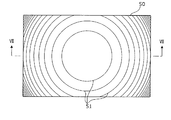
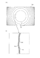
次に、図6及び図7を参照しながら、実施の形態1に係るフレネルレンズ50の具体的構成について説明する。図6は、実施の形態1に係るフレネルレンズを光軸の方向からみた場合の平面図である。図7は、図6のVII-VII断面図である。なお、図7の(a)は、フレネルレンズ50の断面図の全体を示す図であり、図7の(b)は、フレネルレンズ50の断面図の一部を拡大した図である。 [1-3. Configuration of Fresnel lens]
Next, a specific configuration of theFresnel lens 50 according to Embodiment 1 will be described with reference to FIGS. 6 and 7. FIG. 6 is a plan view of the Fresnel lens according to Embodiment 1 as viewed from the direction of the optical axis. 7 is a cross-sectional view taken along the line VII-VII in FIG. 7A is a diagram showing the entire cross-sectional view of the Fresnel lens 50, and FIG. 7B is an enlarged view of a part of the cross-sectional view of the Fresnel lens 50.
次に、図6及び図7を参照しながら、実施の形態1に係るフレネルレンズ50の具体的構成について説明する。図6は、実施の形態1に係るフレネルレンズを光軸の方向からみた場合の平面図である。図7は、図6のVII-VII断面図である。なお、図7の(a)は、フレネルレンズ50の断面図の全体を示す図であり、図7の(b)は、フレネルレンズ50の断面図の一部を拡大した図である。 [1-3. Configuration of Fresnel lens]
Next, a specific configuration of the
図6及び図7に示すように、フレネルレンズ50は、矩形板状の部材であり、光の入射側に配置される平面52と、光の出射側に配置される鋸歯状の凹凸面51とを有する。つまり、フレネルレンズ50の凹凸面51と反対側の面は、平面52である。なお、フレネルレンズ50は、例えば、アクリルなどの樹脂により構成されている。フレネルレンズ50の凹凸面51は、光軸Aに対して傾斜している第1面51aと、光軸Aに略平行な第2面51bとが交互に配置されて形成されている。また、凹凸面51は、図6に示すように、同心円状に形成されている。
As shown in FIGS. 6 and 7, the Fresnel lens 50 is a rectangular plate-like member, and includes a flat surface 52 disposed on the light incident side, and a sawtooth uneven surface 51 disposed on the light emission side. Have That is, the surface of the Fresnel lens 50 opposite to the uneven surface 51 is a flat surface 52. The Fresnel lens 50 is made of a resin such as acrylic. The uneven surface 51 of the Fresnel lens 50 is formed by alternately arranging first surfaces 51 a that are inclined with respect to the optical axis A and second surfaces 51 b that are substantially parallel to the optical axis A. Further, as shown in FIG. 6, the uneven surface 51 is formed concentrically.
第1面51aは、フレネルレンズ50への入射光を所定の焦点に向けて集光する集光面である。つまり、第1面51aは、フレネルレンズ50への入射光を所定の焦点に向けて屈折させる。また、第1面51aは、同心円状に複数形成されており、複数の第1面51aのうち内側(光軸A側)に配置される第1面51aほど光軸Aへの傾斜角が大きくなる。
The first surface 51a is a condensing surface that condenses incident light on the Fresnel lens 50 toward a predetermined focal point. That is, the first surface 51a refracts incident light on the Fresnel lens 50 toward a predetermined focal point. The first surface 51a is formed in a plurality of concentric circles, and the first surface 51a disposed on the inner side (on the optical axis A side) of the plurality of first surfaces 51a has a larger inclination angle to the optical axis A. Become.
第2面51bは、所定の焦点に向けて集光させない壁面である。第2面51bは、凸レンズの厚みを薄くするために、集光面である第1面51aをオフセットさせるために形成された壁面である。
The second surface 51b is a wall surface that does not collect light toward a predetermined focal point. The 2nd surface 51b is a wall surface formed in order to offset the 1st surface 51a which is a condensing surface, in order to make the thickness of a convex lens thin.
互いに隣接しており、かつ、出射側に突出している凸形状を形成している第1面51a及び第2面51bにおいて、第1面51aは、第2面51bよりも外側に配置されている面である。
In the first surface 51a and the second surface 51b that are adjacent to each other and form a convex shape that protrudes toward the emission side, the first surface 51a is disposed outside the second surface 51b. Surface.
フレネルレンズ50は、第1面51aのうち第2面51bと隣接している一部の領域に、遮光マスク53を有する。遮光マスク53は、具体的には、インクジェット印刷などにより、遮光性を有する塗料が吹き付けられることにより形成される塗膜である。なお、遮光マスク53は、第1面51aのうち内側(光軸A側)の一部の領域と、外側の一部の領域とに形成されている。遮光マスク53は、光軸Aの方向からみた場合に同心円状に複数形成されている。
The Fresnel lens 50 has a light shielding mask 53 in a part of the first surface 51a adjacent to the second surface 51b. Specifically, the light-shielding mask 53 is a coating film formed by spraying a paint having a light-shielding property by ink jet printing or the like. The light shielding mask 53 is formed in a part of the first surface 51a on the inner side (optical axis A side) and a part of the outer side. A plurality of light shielding masks 53 are formed concentrically when viewed from the direction of the optical axis A.
[1-4.効果]
実施の形態1に係るフレネルレンズ50によれば、入射光のうち、光軸Aに略平行な第2面51bに反射された入射光a1、a2は遮光マスク53に当たるため、入射光a1、a2がフレネルレンズ50から外部へ向けて出射されることを防ぐことができる。また、入射光のうち、第2面51bに反射されていない入射光a3は遮光マスク53に当たらないため、フレネルレンズ50から外部に向けて出射することができる。このため、第2面51bに反射されることが原因となる迷光の発生を効果的に低減できる。 [1-4. effect]
According to theFresnel lens 50 according to the first embodiment, of the incident light, the incident light a1 and a2 reflected by the second surface 51b substantially parallel to the optical axis A hits the light shielding mask 53, and therefore the incident light a1 and a2 Can be prevented from being emitted from the Fresnel lens 50 to the outside. Further, the incident light a3 that is not reflected by the second surface 51b among the incident light does not strike the light shielding mask 53, and therefore can be emitted outward from the Fresnel lens 50. For this reason, generation | occurrence | production of the stray light caused by being reflected by the 2nd surface 51b can be reduced effectively.
実施の形態1に係るフレネルレンズ50によれば、入射光のうち、光軸Aに略平行な第2面51bに反射された入射光a1、a2は遮光マスク53に当たるため、入射光a1、a2がフレネルレンズ50から外部へ向けて出射されることを防ぐことができる。また、入射光のうち、第2面51bに反射されていない入射光a3は遮光マスク53に当たらないため、フレネルレンズ50から外部に向けて出射することができる。このため、第2面51bに反射されることが原因となる迷光の発生を効果的に低減できる。 [1-4. effect]
According to the
[1-5.実施の形態1の変形例1]
上記実施の形態1に係るフレネルレンズ50では、遮光マスク53は、凹凸面51側に設けられている構成であるが、この構成に限らずに、平面52側に設けられている構成としてもよい。 [1-5.Modification 1 of Embodiment 1]
In theFresnel lens 50 according to the first embodiment, the light shielding mask 53 is provided on the uneven surface 51 side. However, the configuration is not limited to this configuration, and the light shielding mask 53 may be provided on the flat surface 52 side. .
上記実施の形態1に係るフレネルレンズ50では、遮光マスク53は、凹凸面51側に設けられている構成であるが、この構成に限らずに、平面52側に設けられている構成としてもよい。 [1-5.
In the
図8を参照しながら、実施の形態1の変形例1に係るフレネルレンズ50Aの具体的な構成について説明する。図8は、実施の形態1の変形例1に係るフレネルレンズの図7に相当する断面図である。なお、実施の形態1の変形例1に係るフレネルレンズ50Aの遮光マスク53Aを除く構成は、実施の形態1に係るフレネルレンズ50の遮光マスク53を除く構成と同様の構成であるものとする。
A specific configuration of the Fresnel lens 50A according to Modification 1 of Embodiment 1 will be described with reference to FIG. FIG. 8 is a cross-sectional view corresponding to FIG. 7 of the Fresnel lens according to the first modification of the first embodiment. The configuration excluding the light shielding mask 53A of the Fresnel lens 50A according to the first modification of the first embodiment is the same as the configuration excluding the light shielding mask 53 of the Fresnel lens 50 according to the first embodiment.
上述したように、フレネルレンズ50Aは、実施の形態1のフレネルレンズ50と比較して、遮光マスク53Aが形成される面が入射側の平面52であることが異なる。つまり、遮光マスク53Aは、平面52の、第2面51bに対向する位置に形成されている。例えば、遮光マスク53Aは、図8の(b)に示すように、平面52の領域のうちで、第2面51bで反射される角度でフレネルレンズ50Aに入射しようとしている入射光a4、a5がフレネルレンズ50Aに入射することを防ぐ領域に形成されている。一方で、遮光マスク53Aは、平面52のうちで、第2面51bで反射されない角度で入射しようとしている入射光a6がフレネルレンズ50Aに入射する領域には形成されていない。図8の(b)では、入射光a4、a5が遮光マスク53Aによって遮光されていない場合の光の経路を二点鎖線の矢印で示している。
As described above, the Fresnel lens 50A differs from the Fresnel lens 50 of the first embodiment in that the surface on which the light shielding mask 53A is formed is the incident-side flat surface 52. That is, the light shielding mask 53A is formed on the plane 52 at a position facing the second surface 51b. For example, as shown in FIG. 8B, the light shielding mask 53A has incident light a4 and a5 about to enter the Fresnel lens 50A at an angle reflected by the second surface 51b in the region of the plane 52. It is formed in a region that prevents incidence on the Fresnel lens 50A. On the other hand, the light shielding mask 53A is not formed in a region of the plane 52 where the incident light a6 that is about to be incident at an angle that is not reflected by the second surface 51b is incident on the Fresnel lens 50A. In FIG. 8B, the path of light when the incident lights a4 and a5 are not shielded by the light shielding mask 53A is indicated by a two-dot chain line arrow.
なお、遮光マスク53Aが形成される領域は、入射光の角度と、当該入射光が平面52において屈折する角度と、フレネルレンズ50Aの形状とにより求めることができる。
The region where the light shielding mask 53A is formed can be obtained from the angle of incident light, the angle at which the incident light is refracted in the plane 52, and the shape of the Fresnel lens 50A.
なお、遮光マスク53Aは、実施の形態1と同様に、光軸Aの方向からみた場合に同心円状に複数形成されている。
Note that a plurality of light shielding masks 53A are concentrically formed when viewed from the direction of the optical axis A, as in the first embodiment.
[1-6.実施の形態1の変形例2]
図9を参照しながら、実施の形態1の変形例2に係るフレネルレンズユニット70の具体的な構成について説明する。図9は、実施の形態1の変形例2に係るフレネルレンズ50Bの図7に相当する断面図である。なお、フレネルレンズ50Bは、実施の形態1に係るフレネルレンズ50の遮光マスク53を除く構成と同様の構成であるものとする。 [1-6.Modification 2 of Embodiment 1]
A specific configuration of theFresnel lens unit 70 according to the second modification of the first embodiment will be described with reference to FIG. FIG. 9 is a cross-sectional view corresponding to FIG. 7 of the Fresnel lens 50B according to the second modification of the first embodiment. The Fresnel lens 50B has the same configuration as that of the Fresnel lens 50 according to Embodiment 1 except for the light shielding mask 53.
図9を参照しながら、実施の形態1の変形例2に係るフレネルレンズユニット70の具体的な構成について説明する。図9は、実施の形態1の変形例2に係るフレネルレンズ50Bの図7に相当する断面図である。なお、フレネルレンズ50Bは、実施の形態1に係るフレネルレンズ50の遮光マスク53を除く構成と同様の構成であるものとする。 [1-6.
A specific configuration of the
上記実施の形態1及び変形例1に係るフレネルレンズ50、50Aでは、遮光マスク53は、フレネルレンズ50、50Aの表面に設けられている構成であるが、この構成に限らずに、フレネルレンズの光軸上に隣接して配置される透明な板状部材60に遮光マスク61を形成するフレネルレンズユニット70を採用した構成としてもよい。つまり、フレネルレンズ50、50Aの代わりに、遮光マスクが形成されていないフレネルレンズ50Bと遮光マスク61が形成されている板状部材60とを有するフレネルレンズユニット70を採用してもよい。
In the Fresnel lenses 50 and 50A according to the first embodiment and the first modification, the light shielding mask 53 has a configuration provided on the surface of the Fresnel lenses 50 and 50A. It is good also as a structure which employ | adopted the Fresnel lens unit 70 which forms the light shielding mask 61 in the transparent plate-shaped member 60 arrange | positioned adjacent on an optical axis. That is, instead of the Fresnel lenses 50 and 50A, a Fresnel lens unit 70 having a Fresnel lens 50B in which a light shielding mask is not formed and a plate member 60 in which the light shielding mask 61 is formed may be employed.
図9に示すように、フレネルレンズユニット70は、遮光マスクが形成されていないフレネルレンズ50Bと、透明な板状部材60とを有する。
As shown in FIG. 9, the Fresnel lens unit 70 includes a Fresnel lens 50 </ b> B in which a light shielding mask is not formed and a transparent plate-like member 60.
板状部材60は、フレネルレンズ50Bに対向して配置される透明な板状部材(基板)であって、フレネルレンズ50Bの第2面51bに対向する位置に遮光マスク61が形成されている。例えば、遮光マスク61は、図9の(b)に示すように、板状部材60の入射側の面に形成されており、板状部材60の入射側の面のうちで、フレネルレンズ50Bの第2面51bによって反射された光a7、a8が当たる領域に形成されている。つまり、遮光マスク61は、フレネルレンズ50Bの第2面51bによって反射された光a7、a8が、フレネルレンズユニット70から出射することを防ぐ領域に形成されている。一方で、遮光マスク61は、板状部材60の入射側の面のうちで、第2面51bで反射されることなく出射された光a9が当たる領域には形成されていない。
The plate-like member 60 is a transparent plate-like member (substrate) disposed so as to face the Fresnel lens 50B, and a light shielding mask 61 is formed at a position facing the second surface 51b of the Fresnel lens 50B. For example, as shown in FIG. 9B, the light shielding mask 61 is formed on the incident-side surface of the plate-like member 60, and among the incident-side surfaces of the plate-like member 60, the Fresnel lens 50 </ b> B. It is formed in a region where the light a7 and a8 reflected by the second surface 51b strike. That is, the light shielding mask 61 is formed in a region that prevents the light a7 and a8 reflected by the second surface 51b of the Fresnel lens 50B from being emitted from the Fresnel lens unit 70. On the other hand, the light shielding mask 61 is not formed in a region of the incident-side surface of the plate-like member 60 where the light a9 emitted without being reflected by the second surface 51b hits.
なお、遮光マスク61が形成される領域は、フレネルレンズ50Bに入射する光の角度と、当該光が平面52において屈折する角度と、当該光が第2面51bにおいて反射される角度と、当該光が凹凸面51において屈折する角度と、フレネルレンズ50Bの形状とにより求めることができる。
The region where the light shielding mask 61 is formed includes an angle of light incident on the Fresnel lens 50B, an angle at which the light is refracted on the plane 52, an angle at which the light is reflected on the second surface 51b, and the light. Can be determined from the angle at which the concavo-convex surface 51 is refracted and the shape of the Fresnel lens 50B.
[1-7.実施の形態1の変形例3]
上記実施の形態1に係るフレネルレンズ50では、特に言及していないが、遮光マスク53は、図10に示すような形状を有していてもよい。 [1-7. Modification 3 of Embodiment 1]
Although not particularly mentioned in theFresnel lens 50 according to the first embodiment, the light shielding mask 53 may have a shape as shown in FIG.
上記実施の形態1に係るフレネルレンズ50では、特に言及していないが、遮光マスク53は、図10に示すような形状を有していてもよい。 [1-7. Modification 3 of Embodiment 1]
Although not particularly mentioned in the
図10は、実施の形態1の変形例3に係るフレネルレンズを光軸の方向からみた場合の平面図である。なお、図10の(a)は、フレネルレンズ50Cを光軸の方向からみた場合の平面図であり、図10の(b)は、図610(a)の一部を拡大した図である。
FIG. 10 is a plan view of the Fresnel lens according to the third modification of the first embodiment when viewed from the direction of the optical axis. 10A is a plan view when the Fresnel lens 50C is viewed from the direction of the optical axis, and FIG. 10B is an enlarged view of a part of FIG. 610A.
図10の(b)に示すように遮光マスク53Cのマスクパターンの端部は蛇行した形状を有する。具体的には、円状に形成された遮光マスク53Cのマスクパターンは、径方向の外側及び内側の端部が蛇行した形状となっている。
As shown in FIG. 10B, the end of the mask pattern of the light shielding mask 53C has a meandering shape. Specifically, the mask pattern of the light shielding mask 53C formed in a circular shape has a shape in which the radially outer and inner end portions meander.
実施の形態1の遮光マスク53を用いたフレネルレンズ50では、入射光あるいは出射光が遮光マスク53で遮蔽されるため、遮光マスク53のマスクパターンのエッジ部分で光が回折してわずかな迷光を発生する。観察者からは、マスクパターンが淡く光って見えることになる。これに対して、実施の形態1の変形例3の遮光マスク53Cでは、端部の角度に応じて迷光が回折される方向を異なる方向とすることができ、回折光を広い角度に分散することができる。このため、観察者に視認される回折光を低減できる。
In the Fresnel lens 50 using the light shielding mask 53 according to the first embodiment, incident light or outgoing light is shielded by the light shielding mask 53, so that light is diffracted at the edge portion of the mask pattern of the light shielding mask 53 and slight stray light is generated. appear. From the observer's point of view, the mask pattern appears to shine lightly. On the other hand, in the light shielding mask 53C of the third modification of the first embodiment, the direction in which the stray light is diffracted can be made different depending on the angle of the end, and the diffracted light is dispersed over a wide angle. Can do. For this reason, the diffracted light visually recognized by the observer can be reduced.
なお、上述した遮光マスク53Cの形状は、実施の形態1の変形例1及び変形例2のフレネルレンズ50A及びフレネルレンズユニット70の遮光マスク53A、61に適用してもよい。
The shape of the light shielding mask 53C described above may be applied to the light shielding masks 53A and 61 of the Fresnel lens 50A and the Fresnel lens unit 70 according to the first and second modifications of the first embodiment.
(実施の形態2)
次に実施の形態2に係るフレネルレンズ150について説明する。 (Embodiment 2)
Next, theFresnel lens 150 according to Embodiment 2 will be described.
次に実施の形態2に係るフレネルレンズ150について説明する。 (Embodiment 2)
Next, the
実施の形態2は、実施の形態1及びその変形例に係るフレネルレンズ50、50A及びフレネルレンズユニット70では、迷光の原因となる第2面51bでの反射光が出射されないように当該反射光を遮光する遮光マスク53、53A、61を形成している構成であるが、遮光マスク53、53A、61で迷光を遮光しない構成を採用している。
In the second embodiment, in the Fresnel lenses 50 and 50A and the Fresnel lens unit 70 according to the first embodiment and the modification thereof, the reflected light is not emitted from the second surface 51b that causes stray light. The light shielding masks 53, 53A and 61 for shielding light are formed, but the light shielding masks 53, 53A and 61 do not shield stray light.
[2-1.フレネルレンズの構成]
図11を参照しながら、実施の形態2に係るフレネルレンズ150の具体的な構成について説明する。図11は、実施の形態2に係るフレネルレンズの図7に相当する断面図である。 [2-1. Configuration of Fresnel lens]
A specific configuration of theFresnel lens 150 according to the second embodiment will be described with reference to FIG. FIG. 11 is a cross-sectional view corresponding to FIG. 7 of the Fresnel lens according to the second embodiment.
図11を参照しながら、実施の形態2に係るフレネルレンズ150の具体的な構成について説明する。図11は、実施の形態2に係るフレネルレンズの図7に相当する断面図である。 [2-1. Configuration of Fresnel lens]
A specific configuration of the
図11に示すように、実施の形態2に係るフレネルレンズ150は、光の入射側に平面152を有し、光の出射側に鋸歯状の凹凸面151を有する。つまり、フレネルレンズ150の凹凸面151と反対側の面は、平面152である。なお、フレネルレンズ150は、例えば、アクリルなどの樹脂により構成されている。フレネルレンズ150の凹凸面151は、同心円状に形成されている。
As shown in FIG. 11, the Fresnel lens 150 according to the second embodiment has a flat surface 152 on the light incident side and a serrated irregular surface 151 on the light emission side. That is, the surface of the Fresnel lens 150 opposite to the uneven surface 151 is a flat surface 152. The Fresnel lens 150 is made of a resin such as acrylic. The uneven surface 151 of the Fresnel lens 150 is formed concentrically.
第1面151aは、フレネルレンズ50への入射光を所定の焦点に向けて集光する集光面である。つまり、第1面151aは、フレネルレンズ150への入射光を所定の焦点に向けて屈折させる。また、第1面151aは、同心円状に複数形成されており、複数の第1面151aのうち内側(光軸A側)に配置される第1面151aほど光軸Aへの傾斜角が大きくなる。
The first surface 151a is a condensing surface that condenses incident light on the Fresnel lens 50 toward a predetermined focal point. That is, the first surface 151a refracts incident light on the Fresnel lens 150 toward a predetermined focal point. In addition, a plurality of first surfaces 151a are formed concentrically, and the first surface 151a disposed on the inner side (on the optical axis A side) of the plurality of first surfaces 151a has a larger inclination angle to the optical axis A. Become.
第2面151bは、所定の焦点に向けて集光させない壁面である。第2面151bは、凸レンズの厚みを薄くするために、集光面である第1面151aをオフセットさせることで形成された壁面である。
The second surface 151b is a wall surface that does not collect light toward a predetermined focal point. The second surface 151b is a wall surface formed by offsetting the first surface 151a, which is a condensing surface, in order to reduce the thickness of the convex lens.
出射側に突出している凸形状を形成している互いに隣接する第1面151a及び第2面151bにおいて、当該第1面151aは、当該第2面151bよりも外側に配置されている面である。
In the first surface 151a and the second surface 151b that are adjacent to each other and form a convex shape that protrudes toward the emission side, the first surface 151a is a surface that is disposed outside the second surface 151b. .
第2面151bは、第2面151bに当たった光が、アイボックス80の範囲外に進む向きに反射する角度で、フレネルレンズ150の光軸Aに対して傾いて形成されている。第2面151bは、入射側から出射側に向かうほど外側に広がるように光軸Aに対して傾いて形成されている。つまり、第1面151a及び第2面151bは、光軸Aの方向からみた場合に、互いに重ならない領域に形成されている。
The second surface 151b is formed so as to be inclined with respect to the optical axis A of the Fresnel lens 150 at an angle at which the light hitting the second surface 151b is reflected in the direction of traveling out of the range of the eye box 80. The second surface 151b is formed to be inclined with respect to the optical axis A so as to spread outward as it goes from the incident side to the emission side. That is, the first surface 151a and the second surface 151b are formed in regions that do not overlap each other when viewed from the direction of the optical axis A.
また、凹凸面151を形成している複数の第2面151bのうち、第1壁面よりも外側に配置される第2壁面は、第1壁面よりも光軸に対する傾きが大きく形成されている。
In addition, among the plurality of second surfaces 151b forming the uneven surface 151, the second wall surface disposed outside the first wall surface is formed with a larger inclination with respect to the optical axis than the first wall surface.
フレネルレンズ150は、具体的には、次のように、構成することができる。
Specifically, the Fresnel lens 150 can be configured as follows.
運転者12から虚像である画像8までの距離を2m、運転者12からフレネルレンズまでの距離を1m、画像8の水平方向の幅を400mm、アイボックス80の水平方向の幅を130mmとした場合を考える。この場合、フレネルレンズ150の水平方向の幅は270mm、フレネルレンズ150への入射角θinは、フレネルレンズ150の光軸A付近の部分で約±4度、フレネルレンズ150の水平方向の端部で4~12度となる。このとき、フレネルレンズ150の第2面151bの傾斜角θsは、フレネルレンズ150の光軸A付近の部分で4度以上、フレネルレンズ150の水平方向の端部で12度以上とすることで、第2面151bでの反射光をアイボックス80の範囲外にそらすことができる。
When the distance from the driver 12 to the virtual image 8 is 2 m, the distance from the driver 12 to the Fresnel lens is 1 m, the horizontal width of the image 8 is 400 mm, and the horizontal width of the eyebox 80 is 130 mm think of. In this case, the horizontal width of the Fresnel lens 150 is 270 mm, the incident angle θ in to the Fresnel lens 150 is about ± 4 degrees in the vicinity of the optical axis A of the Fresnel lens 150, and the horizontal end of the Fresnel lens 150. It will be 4-12 degrees. At this time, the inclination angle θ s of the second surface 151 b of the Fresnel lens 150 is set to 4 degrees or more at the portion near the optical axis A of the Fresnel lens 150 and 12 degrees or more at the horizontal end of the Fresnel lens 150. The reflected light on the second surface 151b can be diverted out of the range of the eye box 80.
[2-2.効果]
実施の形態2に係るフレネルレンズ150によれば、入射光のうち、焦点に向けて集光させない壁面としての第2面151bに反射された入射光a11は、アイボックス80の範囲外に進む向き(出射角度θo1)で出射されるため、観察者としての運転者12に視認されることを防ぐことができる。また、入射光のうち、第2面151aに反射されていない入射光a12はアイボックス80の範囲内に進む向き(出射角度θo2)で出射されるため、運転者12に視認させることができる。このため、第2面151aに反射されることが原因となる迷光が運転者に視認されることを効果的に低減できる。よってヘッドアップディスプレイ2により表示される画像の劣化を効果的に低減できる。 [2-2. effect]
According to theFresnel lens 150 according to the second embodiment, of the incident light, the incident light a11 reflected by the second surface 151b as a wall surface that is not condensed toward the focal point travels outside the range of the eye box 80. Since it is emitted at (emission angle θ o 1), it can be prevented from being visually recognized by the driver 12 as an observer. In addition, the incident light a12 that is not reflected by the second surface 151a out of the incident light is emitted in a direction (exit angle θ o 2) that travels within the range of the eye box 80, so that it can be visually recognized by the driver 12. it can. For this reason, it can reduce effectively that the driver | operator visually recognizes the stray light caused by being reflected by the 2nd surface 151a. Therefore, the deterioration of the image displayed by the head-up display 2 can be effectively reduced.
実施の形態2に係るフレネルレンズ150によれば、入射光のうち、焦点に向けて集光させない壁面としての第2面151bに反射された入射光a11は、アイボックス80の範囲外に進む向き(出射角度θo1)で出射されるため、観察者としての運転者12に視認されることを防ぐことができる。また、入射光のうち、第2面151aに反射されていない入射光a12はアイボックス80の範囲内に進む向き(出射角度θo2)で出射されるため、運転者12に視認させることができる。このため、第2面151aに反射されることが原因となる迷光が運転者に視認されることを効果的に低減できる。よってヘッドアップディスプレイ2により表示される画像の劣化を効果的に低減できる。 [2-2. effect]
According to the
[2-3.実施の形態2の変形例1]
上記実施の形態2に係るフレネルレンズ150では、第1面151a及び第2面151bは、光軸Aの方向からみた場合に、互いに重ならない領域に形成されている構成であるが、この構成に限らない。 [2-3.Modification 1 of Embodiment 2]
In theFresnel lens 150 according to the second embodiment, the first surface 151a and the second surface 151b are formed in regions that do not overlap with each other when viewed from the direction of the optical axis A. Not exclusively.
上記実施の形態2に係るフレネルレンズ150では、第1面151a及び第2面151bは、光軸Aの方向からみた場合に、互いに重ならない領域に形成されている構成であるが、この構成に限らない。 [2-3.
In the
図12を参照しながら、実施の形態2の変形例1に係るフレネルレンズ150Aの具体的な構成について説明する。図12は、実施の形態2の変形例1に係るフレネルレンズの図7に相当する断面図である。
A specific configuration of the Fresnel lens 150A according to the first modification of the second embodiment will be described with reference to FIG. FIG. 12 is a cross-sectional view corresponding to FIG. 7 of the Fresnel lens according to the first modification of the second embodiment.
図12に示すように、フレネルレンズ150Aは、実施の形態2のフレネルレンズ150と比較して、第1面151Aaと第2面151Abとが、光軸方向に見て重なって配置されている点が異なる。つまり、第2面151Abは、フレネルレンズ150Aへの入射光が壁面に直接当たらない角度でフレネルレンズ150Aの光軸Aに対して傾いて形成されている。
As shown in FIG. 12, in the Fresnel lens 150A, the first surface 151Aa and the second surface 151Ab are arranged so as to overlap each other when viewed in the optical axis direction as compared with the Fresnel lens 150 of the second embodiment. Is different. That is, the second surface 151Ab is formed to be inclined with respect to the optical axis A of the Fresnel lens 150A at an angle at which the incident light on the Fresnel lens 150A does not directly hit the wall surface.
これにより、フレネルレンズ150Aへの入射光が第2面151Abに直接反射することを防ぐことができるため、第2面151Aaに反射されることが原因となる迷光が運転者に視認されることを効果的に低減できる。よってヘッドアップディスプレイ2により表示される画像の劣化を効果的に低減できる。
This prevents incident light on the Fresnel lens 150A from being directly reflected on the second surface 151Ab, so that stray light caused by being reflected on the second surface 151Aa is visually recognized by the driver. It can be effectively reduced. Therefore, the deterioration of the image displayed by the head-up display 2 can be effectively reduced.
(その他の実施の形態)
以上、一つ又は複数の態様に係るヘッドアップディスプレイについて、上記実施の形態に基づいて説明したが、本発明は、この実施の形態に限定されるものではない。本発明の趣旨を逸脱しない限り、当業者が思い付く各種変形を本実施の形態に施したものや、異なる実施の形態又は変形例における構成要素を組み合わせて構築される形態も、一つ又は複数の態様の範囲内に含まれてもよい。 (Other embodiments)
The head-up display according to one or more aspects has been described based on the above embodiment, but the present invention is not limited to this embodiment. Unless departing from the spirit of the present invention, one or a plurality of modifications may be made to the present embodiment which are conceived by those skilled in the art or a combination of components in different embodiments or modifications. It may be included within the scope of the embodiments.
なお、通常のヘッドアップディスプレイは、視野角が20度以下と比較的小さいため、フレネルレンズに入射する光の入射角分布も比較的小さく、壁面の傾斜角も20度以下と比較的小さく設定できるため、光ロスが少なく効果的に反射光による迷光を防ぐことができる。しかしながら、本発明は、この実施の形態に限定されるものではない。
Since a normal head-up display has a relatively small viewing angle of 20 degrees or less, the incident angle distribution of light incident on the Fresnel lens is relatively small, and the inclination angle of the wall surface can be set to a relatively small value of 20 degrees or less. Therefore, stray light due to reflected light can be effectively prevented with little optical loss. However, the present invention is not limited to this embodiment.
例えば、上記各実施の形態では、ヘッドアップディスプレイ2(2A)を自動車4に搭載する場合について説明したが、これに限定されず、例えば自動二輪車、航空機、電車又は船舶等に搭載されてもよい。
For example, in each of the above-described embodiments, the case where the head-up display 2 (2A) is mounted on the automobile 4 has been described. However, the present invention is not limited to this. .
また、ヘッドアップディスプレイ2(2A)を車両に搭載する場合について説明したが、これに限定されず、例えばウェアラブルデバイスとして構成される眼鏡等に搭載されてもよい。
Further, although the case where the head-up display 2 (2A) is mounted on the vehicle has been described, the present invention is not limited thereto, and may be mounted on, for example, glasses configured as a wearable device.
なお、上記実施の形態において、各構成要素は、専用のハードウェアで構成されるか、各構成要素に適したソフトウェアプログラムを実行することによって実現されてもよい。各構成要素は、CPU又はプロセッサ等のプログラム実行部が、ハードディスク又は半導体メモリ等の記録媒体に記録されたソフトウェアプログラムを読み出して実行することによって実現されてもよい。
In the above embodiment, each component may be configured by dedicated hardware or may be realized by executing a software program suitable for each component. Each component may be realized by a program execution unit such as a CPU or a processor reading and executing a software program recorded on a recording medium such as a hard disk or a semiconductor memory.
また、以下のような場合も本発明に含まれる。
The following cases are also included in the present invention.
(1)上記の各装置は、具体的には、マイクロプロセッサ、ROM(Read Only Memory)、RAM(Read Access Memory)、ハードディスクユニット、ディスプレイユニット、キーボード、マウスなどから構成されるコンピュータシステムで実現され得る。RAM又はハードディスクユニットには、コンピュータプログラムが記憶されている。マイクロプロセッサが、コンピュータプログラムにしたがって動作することにより、各装置は、その機能を達成する。ここでコンピュータプログラムは、所定の機能を達成するために、コンピュータに対する指令を示す命令コードが複数個組み合わされて構成されたものである。
(1) Each of the above devices is specifically realized by a computer system including a microprocessor, a ROM (Read Only Memory), a RAM (Read Access Memory), a hard disk unit, a display unit, a keyboard, a mouse, and the like. obtain. A computer program is stored in the RAM or the hard disk unit. Each device achieves its functions by the microprocessor operating according to the computer program. Here, the computer program is configured by combining a plurality of instruction codes indicating instructions for the computer in order to achieve a predetermined function.
(2)上記の各装置を構成する構成要素の一部又は全部は、1個のシステムLSI(Large Scale Integration:大規模集積回路)から構成されているとしてもよい。システムLSIは、複数の構成部を1個のチップ上に集積して製造された超多機能LSIであり、具体的には、マイクロプロセッサ、ROM、RAMなどを含んで構成されるコンピュータシステムである。ROMには、コンピュータプログラムが記憶されている。マイクロプロセッサが、ROMからRAMにコンピュータプログラムをロードし、ロードしたコンピュータプログラムにしたがって演算等の動作することにより、システムLSIは、その機能を達成する。
(2) A part or all of the constituent elements constituting each of the above devices may be constituted by one system LSI (Large Scale Integration). The system LSI is an ultra-multifunctional LSI manufactured by integrating a plurality of components on a single chip, and specifically, a computer system including a microprocessor, ROM, RAM, and the like. . A computer program is stored in the ROM. The system LSI achieves its functions by the microprocessor loading a computer program from the ROM to the RAM and performing operations such as operations in accordance with the loaded computer program.
(3)上記の各装置を構成する構成要素の一部又は全部は、各装置に脱着可能なIC(Integrated Circuit)カード又は単体のモジュールから構成されてもよい。ICカード又はモジュールは、マイクロプロセッサ、ROM、RAMなどから構成されるコンピュータシステムである。ICカード又はモジュールには、上記の超多機能LSIが含まれてもよい。マイクロプロセッサが、コンピュータプログラムにしたがって動作することにより、ICカード又はモジュールは、その機能を達成する。このICカード又はこのモジュールは、耐タンパ性を有してもよい。
(3) A part or all of the constituent elements constituting each of the above devices may be configured by an IC (Integrated Circuit) card that can be attached to and detached from each device or a single module. The IC card or module is a computer system that includes a microprocessor, ROM, RAM, and the like. The IC card or the module may include the super multifunctional LSI described above. The IC card or the module achieves its function by the microprocessor operating according to the computer program. This IC card or this module may have tamper resistance.
(4)本発明は、上記に示す方法で実現されてもよい。また、これらの方法をコンピュータにより実現するコンピュータプログラムで実現してもよいし、コンピュータプログラムからなるデジタル信号で実現してもよい。
(4) The present invention may be realized by the method described above. Further, these methods may be realized by a computer program realized by a computer, or may be realized by a digital signal consisting of a computer program.
また、本発明は、コンピュータプログラム又はデジタル信号をコンピュータ読み取り可能な記録媒体、例えば、フレキシブルディスク、ハードディスク、CD(Compact Disc)-ROM、MO(Magneto-Optical disc)、DVD(Digital Versatile Disc)、DVD-ROM、DVD-RAM、BD(Blu-ray(登録商標) Disc)、半導体メモリなどに記録したもので実現してもよい。また、これらの記録媒体に記録されているデジタル信号で実現してもよい。
The present invention also relates to a recording medium capable of reading a computer program or a digital signal, such as a flexible disk, hard disk, CD (Compact Disc) -ROM, MO (Magneto-Optical disc), DVD (Digital Versatile Disc), DVD. It may be realized by recording on a ROM, DVD-RAM, BD (Blu-ray (registered trademark) Disc), semiconductor memory or the like. Moreover, you may implement | achieve with the digital signal currently recorded on these recording media.
また、本発明は、コンピュータプログラム又はデジタル信号を、電気通信回線、無線又は有線通信回線、インターネットを代表とするネットワーク、データ放送等を経由して伝送してもよい。
In the present invention, a computer program or a digital signal may be transmitted via an electric communication line, a wireless or wired communication line, a network represented by the Internet, a data broadcast, or the like.
また、本発明は、マイクロプロセッサとメモリを備えたコンピュータシステムであって、メモリは、コンピュータプログラムを記憶しており、マイクロプロセッサは、コンピュータプログラムにしたがって動作してもよい。
The present invention is also a computer system including a microprocessor and a memory. The memory stores a computer program, and the microprocessor may operate according to the computer program.
また、プログラム又はデジタル信号を記録媒体に記録して移送することにより、又はプログラム又はデジタル信号をネットワーク等を経由して移送することにより、独立した他のコンピュータシステムにより実施するとしてもよい。
Also, the program or digital signal may be recorded on a recording medium and transferred, or the program or digital signal may be transferred via a network or the like, and may be implemented by another independent computer system.
(5)上記実施の形態及び上記変形例をそれぞれ組み合わせるとしてもよい。
(5) The above embodiment and the above modifications may be combined.
本発明のヘッドアップディスプレイは、例えば車載用のヘッドアップディスプレイ等に適用することができる。
The head-up display of the present invention can be applied to, for example, a vehicle-mounted head-up display.
2 ヘッドアップディスプレイ
4 自動車
6 ダッシュボード
8 画像
10 ウインドシールド
11 領域
12 運転者
14 景色
16 空間
18 鉛直画像
20 奥行き画像
22 歩行者
24 道路
26 投射部
28 可動スクリーン
30 駆動部
32 投影部
34 制御部
36 光源
38 走査部
44 拡大レンズ
46 第1の反射板
48 第2の反射板
50,50A,50B,150,150A フレネルレンズ
51,151 凹凸面
51a,151a,151Aa 第1面
51b,151b,151Ab 第2面
52,152 平面
53,53A,61 遮光マスク
60 板状部材
70 フレネルレンズユニット
80 アイボックス
a1~a6,a11,a12 入射光
a7~a9 光 2Head Up Display 4 Car 6 Dashboard 8 Image 10 Windshield 11 Area 12 Driver 14 Scene 16 Space 18 Vertical Image 20 Depth Image 22 Pedestrian 24 Road 26 Projection Unit 28 Movable Screen 30 Drive Unit 32 Projection Unit 34 Control Unit 36 Light source 38 Scanning unit 44 Magnifying lens 46 First reflecting plate 48 Second reflecting plate 50, 50A, 50B, 150, 150A Fresnel lens 51, 151 Uneven surface 51a, 151a, 151Aa First surface 51b, 151b, 151Ab Second Surface 52, 152 Plane 53, 53A, 61 Shading mask 60 Plate member 70 Fresnel lens unit 80 Eye box a1 to a6, a11, a12 Incident light a7 to a9 light
4 自動車
6 ダッシュボード
8 画像
10 ウインドシールド
11 領域
12 運転者
14 景色
16 空間
18 鉛直画像
20 奥行き画像
22 歩行者
24 道路
26 投射部
28 可動スクリーン
30 駆動部
32 投影部
34 制御部
36 光源
38 走査部
44 拡大レンズ
46 第1の反射板
48 第2の反射板
50,50A,50B,150,150A フレネルレンズ
51,151 凹凸面
51a,151a,151Aa 第1面
51b,151b,151Ab 第2面
52,152 平面
53,53A,61 遮光マスク
60 板状部材
70 フレネルレンズユニット
80 アイボックス
a1~a6,a11,a12 入射光
a7~a9 光 2
Claims (5)
- 観察者の眼が存在すると想定された所定の範囲であるアイボックスに向けて映像を構成する光を放出する光学系を備えるヘッドアップディスプレイであって、
前記光学系は、光軸を中心として同心円状に形成される凹凸面であって、入射光を焦点に向けて集光する集光面と、前記焦点に向けて集光させない壁面とが交互に配置されて形成される、断面が鋸歯状の凹凸面を有するフレネルレンズを含み、
前記壁面は、前記壁面に当たった光が、前記アイボックスの範囲外に進む向きに反射する角度で、前記フレネルレンズの前記光軸に対して傾いて形成されている
ヘッドアップディスプレイ。 A head-up display including an optical system that emits light constituting an image toward an eye box that is a predetermined range in which an observer's eyes are assumed to exist,
The optical system is a concavo-convex surface formed concentrically with an optical axis as a center, and a condensing surface that condenses incident light toward a focal point and a wall surface that does not condense toward the focal point alternately A Fresnel lens having an uneven surface with a sawtooth cross-section formed by being disposed;
The wall surface is formed so as to be inclined with respect to the optical axis of the Fresnel lens at an angle at which light hitting the wall surface is reflected in a direction of traveling out of the range of the eye box. - 前記凹凸面を形成している複数の前記壁面のうち、第1壁面よりも外側に配置される第2壁面は、前記第1壁面よりも前記光軸に対する傾きが大きく形成されている
請求項1に記載のヘッドアップディスプレイ。 2. The second wall surface arranged outside the first wall surface among the plurality of wall surfaces forming the uneven surface is formed to have a larger inclination with respect to the optical axis than the first wall surface. The head-up display described in 1. - 観察者の眼が存在すると想定された所定の範囲であるアイボックスに向けて映像を構成する光を放出する光学系を備えるヘッドアップディスプレイであって、
前記光学系は、光軸を中心として同心円状に形成される凹凸面であって、入射光を焦点に集光する集光面と、前記焦点に向けて集光させない壁面とが交互に配置されて形成される、断面が鋸歯状の凹凸面を有するフレネルレンズを含み、
前記壁面は、前記フレネルレンズへの入射光が前記壁面に直接当たらない角度で、前記フレネルレンズの光軸に対して傾いて形成されている
ヘッドアップディスプレイ。 A head-up display including an optical system that emits light constituting an image toward an eye box that is a predetermined range in which an observer's eyes are assumed to exist,
The optical system is a concavo-convex surface formed concentrically around the optical axis, and a condensing surface that condenses incident light at a focal point and a wall surface that does not condense toward the focal point are alternately arranged. Including a Fresnel lens having a serrated uneven surface in cross section,
The wall surface is formed so as to be inclined with respect to the optical axis of the Fresnel lens at an angle at which light incident on the Fresnel lens does not directly hit the wall surface. - 前記集光面と前記壁面とは、前記光軸方向にみて重なって配置されている
請求項3に記載のヘッドアップディスプレイ。 The head-up display according to claim 3, wherein the condensing surface and the wall surface are arranged so as to overlap each other when viewed in the optical axis direction. - さらに、
光を出射する光源と、
前記光源からの光を走査する走査部と、
前記走査部からの光が透過することにより画像が形成されるスクリーンと、を備え、
前記光学系は、前記スクリーンに形成された前記画像の虚像を空間に表示する
請求項1から4のいずれか1項に記載のヘッドアップディスプレイ。 further,
A light source that emits light;
A scanning unit that scans light from the light source;
A screen on which an image is formed by transmission of light from the scanning unit,
The head-up display according to any one of claims 1 to 4, wherein the optical system displays a virtual image of the image formed on the screen in a space.
Priority Applications (2)
| Application Number | Priority Date | Filing Date | Title |
|---|---|---|---|
| DE112016006259.1T DE112016006259T5 (en) | 2016-01-20 | 2016-12-02 | Head-Up Display |
| US16/026,109 US10642032B2 (en) | 2016-01-20 | 2018-07-03 | Head-up display |
Applications Claiming Priority (2)
| Application Number | Priority Date | Filing Date | Title |
|---|---|---|---|
| JP2016009292A JP6628137B2 (en) | 2016-01-20 | 2016-01-20 | Head-up display |
| JP2016-009292 | 2016-01-20 |
Related Child Applications (1)
| Application Number | Title | Priority Date | Filing Date |
|---|---|---|---|
| US16/026,109 Continuation US10642032B2 (en) | 2016-01-20 | 2018-07-03 | Head-up display |
Publications (1)
| Publication Number | Publication Date |
|---|---|
| WO2017125979A1 true WO2017125979A1 (en) | 2017-07-27 |
Family
ID=59362168
Family Applications (1)
| Application Number | Title | Priority Date | Filing Date |
|---|---|---|---|
| PCT/JP2016/005048 WO2017125979A1 (en) | 2016-01-20 | 2016-12-02 | Head-up display |
Country Status (4)
| Country | Link |
|---|---|
| US (1) | US10642032B2 (en) |
| JP (1) | JP6628137B2 (en) |
| DE (1) | DE112016006259T5 (en) |
| WO (1) | WO2017125979A1 (en) |
Cited By (2)
| Publication number | Priority date | Publication date | Assignee | Title |
|---|---|---|---|---|
| TWI651549B (en) * | 2018-02-12 | 2019-02-21 | 玉晶光電股份有限公司 | Fresnel lens |
| US10732327B2 (en) | 2018-02-12 | 2020-08-04 | Genius Electronic Optical Co., Ltd. | Fresnel lens |
Families Citing this family (3)
| Publication number | Priority date | Publication date | Assignee | Title |
|---|---|---|---|---|
| CN107632388B (en) * | 2017-10-24 | 2024-04-02 | 歌尔光学科技有限公司 | Eyepiece and head-mounted display device |
| CN110146994B (en) * | 2019-05-21 | 2021-08-06 | 京东方科技集团股份有限公司 | Light filtering structure, glasses and display panel |
| CN112622767A (en) | 2019-10-08 | 2021-04-09 | 松下知识产权经营株式会社 | Display system and electronic rearview mirror system provided with same |
Citations (6)
| Publication number | Priority date | Publication date | Assignee | Title |
|---|---|---|---|---|
| JPH0875906A (en) * | 1994-09-02 | 1996-03-22 | Casio Comput Co Ltd | Fresnel lens |
| JPH09218465A (en) * | 1996-02-09 | 1997-08-19 | Minolta Co Ltd | Screen device |
| JP2005084172A (en) * | 2003-09-05 | 2005-03-31 | Calsonic Kansei Corp | Display unit for vehicle |
| JP2013137442A (en) * | 2011-12-28 | 2013-07-11 | Panasonic Corp | Fresnel lens |
| JP2014191285A (en) * | 2013-03-28 | 2014-10-06 | Shimadzu Corp | Rear projection type display apparatus and fresnel lens used for the same |
| JP2015184432A (en) * | 2014-03-24 | 2015-10-22 | アイシン・エィ・ダブリュ株式会社 | Head-up display device |
Family Cites Families (12)
| Publication number | Priority date | Publication date | Assignee | Title |
|---|---|---|---|---|
| JP4258353B2 (en) * | 2003-10-31 | 2009-04-30 | コニカミノルタオプト株式会社 | Optical element |
| TWI294023B (en) * | 2006-03-17 | 2008-03-01 | Ind Tech Res Inst | Reflective illumination device |
| US8077392B2 (en) * | 2006-06-13 | 2011-12-13 | Panasonic Corporation | Composite optical element |
| JP5147693B2 (en) * | 2006-06-13 | 2013-02-20 | パナソニック株式会社 | Compound optical element |
| JP5393020B2 (en) * | 2007-04-26 | 2014-01-22 | 株式会社リコー | Optical pickup and optical information processing apparatus |
| JP2009069457A (en) * | 2007-09-13 | 2009-04-02 | Seiko Epson Corp | Optical scanning element, and image display device |
| US9103956B2 (en) * | 2010-07-28 | 2015-08-11 | Flex Lighting Ii, Llc | Light emitting device with optical redundancy |
| JP2014043205A (en) | 2012-08-28 | 2014-03-13 | Dainippon Printing Co Ltd | Image display system for vehicle |
| DE102013014277A1 (en) * | 2013-08-27 | 2015-03-05 | Rosenberger Hochfrequenztechnik Gmbh & Co. Kg | Device for coupling pumping light into a fiber and method for producing such a device |
| JP2015161732A (en) * | 2014-02-26 | 2015-09-07 | 矢崎総業株式会社 | Display light projection optical device |
| US10544918B2 (en) * | 2014-10-23 | 2020-01-28 | Daicel Corporation | Fresnel lens and optical device provided with same |
| US9928769B2 (en) * | 2015-09-29 | 2018-03-27 | Panasonic Intellectual Property Management Co., Ltd. | Head-up display and vehicle equipped with head-up display |
-
2016
- 2016-01-20 JP JP2016009292A patent/JP6628137B2/en active Active
- 2016-12-02 DE DE112016006259.1T patent/DE112016006259T5/en active Pending
- 2016-12-02 WO PCT/JP2016/005048 patent/WO2017125979A1/en active Application Filing
-
2018
- 2018-07-03 US US16/026,109 patent/US10642032B2/en active Active
Patent Citations (6)
| Publication number | Priority date | Publication date | Assignee | Title |
|---|---|---|---|---|
| JPH0875906A (en) * | 1994-09-02 | 1996-03-22 | Casio Comput Co Ltd | Fresnel lens |
| JPH09218465A (en) * | 1996-02-09 | 1997-08-19 | Minolta Co Ltd | Screen device |
| JP2005084172A (en) * | 2003-09-05 | 2005-03-31 | Calsonic Kansei Corp | Display unit for vehicle |
| JP2013137442A (en) * | 2011-12-28 | 2013-07-11 | Panasonic Corp | Fresnel lens |
| JP2014191285A (en) * | 2013-03-28 | 2014-10-06 | Shimadzu Corp | Rear projection type display apparatus and fresnel lens used for the same |
| JP2015184432A (en) * | 2014-03-24 | 2015-10-22 | アイシン・エィ・ダブリュ株式会社 | Head-up display device |
Cited By (2)
| Publication number | Priority date | Publication date | Assignee | Title |
|---|---|---|---|---|
| TWI651549B (en) * | 2018-02-12 | 2019-02-21 | 玉晶光電股份有限公司 | Fresnel lens |
| US10732327B2 (en) | 2018-02-12 | 2020-08-04 | Genius Electronic Optical Co., Ltd. | Fresnel lens |
Also Published As
| Publication number | Publication date |
|---|---|
| JP2017129751A (en) | 2017-07-27 |
| DE112016006259T5 (en) | 2018-11-08 |
| US20180314064A1 (en) | 2018-11-01 |
| US10642032B2 (en) | 2020-05-05 |
| JP6628137B2 (en) | 2020-01-08 |
Similar Documents
| Publication | Publication Date | Title |
|---|---|---|
| JP6610887B2 (en) | Fresnel lens and head-up display | |
| US10642032B2 (en) | Head-up display | |
| JP6098375B2 (en) | Head-up display device | |
| JP7065383B2 (en) | Display systems, information presentation systems, display system control methods, programs, and moving objects | |
| JP6749334B2 (en) | Projection optical system and head-up display device | |
| JP6375825B2 (en) | Head-up display device | |
| JP6489371B2 (en) | Display device | |
| JP6056680B2 (en) | Head-up display device | |
| JP6451686B2 (en) | Head-up display device | |
| WO2017125974A1 (en) | Display device | |
| JP2017128234A (en) | Display device | |
| JP2017067944A (en) | Display image generation device and image display device | |
| JP2015022158A (en) | Optical scanner and image display device | |
| US10432899B2 (en) | Image display device | |
| JP2018040842A (en) | Head-up display device | |
| JP6710017B2 (en) | Image display | |
| JP6820502B2 (en) | Image display device | |
| JP7367525B2 (en) | Display devices, display systems and mobile objects | |
| JP6726883B2 (en) | Display system, moving body, and control method for display system | |
| WO2020189191A1 (en) | Projector, display system, and mobile object | |
| KR102144462B1 (en) | Head-up display device | |
| WO2018030203A1 (en) | Display device | |
| US10502953B2 (en) | Display device, and mobile body having same | |
| JP2020194122A (en) | Optical scanner, display system, and movable body | |
| JP2019179065A (en) | Headup display device |
Legal Events
| Date | Code | Title | Description |
|---|---|---|---|
| 121 | Ep: the epo has been informed by wipo that ep was designated in this application |
Ref document number: 16886224 Country of ref document: EP Kind code of ref document: A1 |
|
| 122 | Ep: pct application non-entry in european phase |
Ref document number: 16886224 Country of ref document: EP Kind code of ref document: A1 |