JP6610887B2 - Fresnel lens and head-up display - Google Patents
Fresnel lens and head-up display Download PDFInfo
- Publication number
- JP6610887B2 JP6610887B2 JP2016009299A JP2016009299A JP6610887B2 JP 6610887 B2 JP6610887 B2 JP 6610887B2 JP 2016009299 A JP2016009299 A JP 2016009299A JP 2016009299 A JP2016009299 A JP 2016009299A JP 6610887 B2 JP6610887 B2 JP 6610887B2
- Authority
- JP
- Japan
- Prior art keywords
- fresnel lens
- light
- shielding mask
- optical axis
- light shielding
- Prior art date
- Legal status (The legal status is an assumption and is not a legal conclusion. Google has not performed a legal analysis and makes no representation as to the accuracy of the status listed.)
- Active
Links
- 230000003287 optical effect Effects 0.000 claims description 51
- 230000005540 biological transmission Effects 0.000 claims description 3
- 230000001788 irregular Effects 0.000 claims description 2
- 238000012986 modification Methods 0.000 description 23
- 230000004048 modification Effects 0.000 description 23
- 238000004590 computer program Methods 0.000 description 13
- 238000010586 diagram Methods 0.000 description 11
- 230000006870 function Effects 0.000 description 8
- 239000000470 constituent Substances 0.000 description 7
- 238000000034 method Methods 0.000 description 3
- NIXOWILDQLNWCW-UHFFFAOYSA-N acrylic acid group Chemical group C(C=C)(=O)O NIXOWILDQLNWCW-UHFFFAOYSA-N 0.000 description 2
- 238000004891 communication Methods 0.000 description 2
- 230000000694 effects Effects 0.000 description 2
- 239000011521 glass Substances 0.000 description 2
- 238000004519 manufacturing process Methods 0.000 description 2
- 239000011347 resin Substances 0.000 description 2
- 229920005989 resin Polymers 0.000 description 2
- 239000004065 semiconductor Substances 0.000 description 2
- 230000003190 augmentative effect Effects 0.000 description 1
- 239000011248 coating agent Substances 0.000 description 1
- 238000000576 coating method Methods 0.000 description 1
- 238000007641 inkjet printing Methods 0.000 description 1
- 230000010354 integration Effects 0.000 description 1
- 239000000463 material Substances 0.000 description 1
- 239000003973 paint Substances 0.000 description 1
- 238000005507 spraying Methods 0.000 description 1
- 239000000758 substrate Substances 0.000 description 1
Images


Classifications
-
- G—PHYSICS
- G02—OPTICS
- G02B—OPTICAL ELEMENTS, SYSTEMS OR APPARATUS
- G02B3/00—Simple or compound lenses
- G02B3/02—Simple or compound lenses with non-spherical faces
- G02B3/08—Simple or compound lenses with non-spherical faces with discontinuous faces, e.g. Fresnel lens
-
- B—PERFORMING OPERATIONS; TRANSPORTING
- B60—VEHICLES IN GENERAL
- B60K—ARRANGEMENT OR MOUNTING OF PROPULSION UNITS OR OF TRANSMISSIONS IN VEHICLES; ARRANGEMENT OR MOUNTING OF PLURAL DIVERSE PRIME-MOVERS IN VEHICLES; AUXILIARY DRIVES FOR VEHICLES; INSTRUMENTATION OR DASHBOARDS FOR VEHICLES; ARRANGEMENTS IN CONNECTION WITH COOLING, AIR INTAKE, GAS EXHAUST OR FUEL SUPPLY OF PROPULSION UNITS IN VEHICLES
- B60K35/00—Arrangement of adaptations of instruments
-
- B60K35/23—
-
- G—PHYSICS
- G02—OPTICS
- G02B—OPTICAL ELEMENTS, SYSTEMS OR APPARATUS
- G02B27/00—Optical systems or apparatus not provided for by any of the groups G02B1/00 - G02B26/00, G02B30/00
- G02B27/01—Head-up displays
-
- G—PHYSICS
- G02—OPTICS
- G02B—OPTICAL ELEMENTS, SYSTEMS OR APPARATUS
- G02B27/00—Optical systems or apparatus not provided for by any of the groups G02B1/00 - G02B26/00, G02B30/00
- G02B27/01—Head-up displays
- G02B27/0101—Head-up displays characterised by optical features
-
- B60K2360/334—
-
- G—PHYSICS
- G01—MEASURING; TESTING
- G01C—MEASURING DISTANCES, LEVELS OR BEARINGS; SURVEYING; NAVIGATION; GYROSCOPIC INSTRUMENTS; PHOTOGRAMMETRY OR VIDEOGRAMMETRY
- G01C21/00—Navigation; Navigational instruments not provided for in groups G01C1/00 - G01C19/00
- G01C21/26—Navigation; Navigational instruments not provided for in groups G01C1/00 - G01C19/00 specially adapted for navigation in a road network
- G01C21/34—Route searching; Route guidance
- G01C21/36—Input/output arrangements for on-board computers
- G01C21/3626—Details of the output of route guidance instructions
- G01C21/365—Guidance using head up displays or projectors, e.g. virtual vehicles or arrows projected on the windscreen or on the road itself
-
- G—PHYSICS
- G02—OPTICS
- G02B—OPTICAL ELEMENTS, SYSTEMS OR APPARATUS
- G02B27/00—Optical systems or apparatus not provided for by any of the groups G02B1/00 - G02B26/00, G02B30/00
- G02B27/01—Head-up displays
- G02B27/0101—Head-up displays characterised by optical features
- G02B2027/0118—Head-up displays characterised by optical features comprising devices for improving the contrast of the display / brillance control visibility
Description
本発明は、フレネルレンズ及びヘッドアップディスプレイに関する。 The present invention relates to a Fresnel lens and a head-up display.
画像を表示するための表示装置として、例えば車両用のヘッドアップディスプレイ(HUD)が知られている(例えば、特許文献1参照)。このヘッドアップディスプレイは、いわゆるAR(Augmented Reality)を用いたものであり、可動スクリーンに形成された画像の虚像を車両のウインドシールド(フロントガラス)の前方の空間に表示する。これにより、運転者は、ウインドシールドの前方の景色上に、運転に関する情報(例えばカーナビゲーション情報等)を重ね合わせて見ることができる。 As a display device for displaying an image, for example, a head-up display (HUD) for a vehicle is known (for example, see Patent Document 1). This head-up display uses so-called AR (Augmented Reality), and displays a virtual image of an image formed on a movable screen in a space in front of a windshield (front glass) of a vehicle. As a result, the driver can superimpose driving information (for example, car navigation information) on the scenery in front of the windshield.
ところで、特許文献1のヘッドアップディスプレイでは、映像系の光学系(例えば接眼光学系)にフレネルレンズが用いられている。このため、上記特許文献1のヘッドアップディスプレイでは、同心円状の迷光が発生するという問題がある。
By the way, in the head-up display of
そこで、本発明は、同心円状の迷光の発生を低減できるフレネルレンズを提供する。 Therefore, the present invention provides a Fresnel lens that can reduce the generation of concentric stray light.
本発明の一態様に係るフレネルレンズは、光軸に対して傾斜している第1面と、前記光軸に略平行な第2面とが交互に配置されて形成される鋸歯状の凹凸面を有するフレネルレンズであって、前記第2面に対応する位置に、遮光マスクが形成されている。 A Fresnel lens according to an aspect of the present invention is a sawtooth-shaped uneven surface formed by alternately arranging a first surface inclined with respect to an optical axis and a second surface substantially parallel to the optical axis. A light shielding mask is formed at a position corresponding to the second surface.
本発明の一態様に係るヘッドアップディスプレイは、光を出射する光源と、前記光源からの光を走査する走査部と、前記走査部からの光が透過することにより画像が形成されるスクリーンと、前記スクリーンに形成された前記画像の虚像を空間に表示する光学系と、を備え、前記光学系は、上記のフレネルレンズ、または、上記のフレネルレンズユニットを含む。 A head-up display according to an aspect of the present invention includes a light source that emits light, a scanning unit that scans light from the light source, a screen on which an image is formed by transmission of light from the scanning unit, An optical system that displays a virtual image of the image formed on the screen in a space, and the optical system includes the Fresnel lens or the Fresnel lens unit.
本発明のフレネルレンズは、同心円状の迷光の発生を低減できる。 The Fresnel lens of the present invention can reduce the generation of concentric stray light.
(本発明の基礎となった知見)
本発明者は、「背景技術」の欄において記載した技術に関し、以下の問題が生じることを見出した。
(Knowledge that became the basis of the present invention)
The inventor has found that the following problems occur with respect to the technique described in the “Background Art” column.
特許文献1のヘッドアップディスプレイでは、フレネルレンズの段差形状において散乱光及び反射光のために同心円状の迷光が発生するため、当該迷光が画像に重畳し、画質が劣化するという課題がある。
In the head-up display of
このような問題を解決するために、本発明の一態様に係るフレネルレンズは、光軸に対して傾斜している第1面と、前記光軸に略平行な第2面とが交互に配置されて形成される鋸歯状の凹凸面を有するフレネルレンズであって、前記第2面に対応する位置に、遮光マスクが形成されている。 In order to solve such a problem, in the Fresnel lens according to one aspect of the present invention, first surfaces that are inclined with respect to the optical axis and second surfaces that are substantially parallel to the optical axis are alternately arranged. A light-shielding mask is formed at a position corresponding to the second surface, which is a Fresnel lens having a serrated uneven surface formed in this manner.
本態様によれば、入射光のうち光軸に略平行な第2面に反射された入射光は遮光マスクに当たるため、入射光がフレネルレンズから外部へ向けて出射されることを防ぐことができる。また、入射光のうち光軸に略平行な第2面に反射されていない入射光は遮光マスクに当たらないため、フレネルレンズから外部に向けて出射することができる。このため、第2面に反射されることが原因となる迷光の発生を効果的に低減できる。 According to this aspect, since the incident light reflected by the second surface substantially parallel to the optical axis of the incident light hits the light shielding mask, it is possible to prevent the incident light from being emitted outward from the Fresnel lens. . Further, incident light that is not reflected by the second surface that is substantially parallel to the optical axis out of the incident light does not strike the light shielding mask, and thus can be emitted outward from the Fresnel lens. For this reason, generation | occurrence | production of the stray light caused by being reflected by the 2nd surface can be reduced effectively.
また、前記遮光マスクは、前記第1面のうち前記第2面と隣接している一部の領域に形成されていてもよい。 The light shielding mask may be formed in a part of the first surface adjacent to the second surface.
また、前記フレネルレンズの前記凹凸面と反対側の面は平面であり、前記遮光マスクは、前記反対側の面の前記第2面に対向する位置に形成されていてもよい。 The surface of the Fresnel lens opposite to the concave-convex surface may be a flat surface, and the light shielding mask may be formed at a position facing the second surface of the opposite surface.
また、前記遮光マスクは、当該遮光マスク上のマスクパターンの端部が蛇行している形状を有してもよい。 The light shielding mask may have a shape in which an end portion of the mask pattern on the light shielding mask meanders.
また、本発明の一態様に係るフレネルレンズユニットは、光軸に対して傾斜している第1面と、前記光軸に略平行な第2面とが交互に配置されて形成される鋸歯状の凹凸面を有するフレネルレンズであって、前記フレネルレンズに対向して配置される透明な板状部材であって、前記第2面に対向する位置に遮光マスクが形成されている板状部材と、を備える。 Further, the Fresnel lens unit according to one aspect of the present invention is a sawtooth shape formed by alternately arranging a first surface inclined with respect to the optical axis and a second surface substantially parallel to the optical axis. A transparent plate-like member disposed opposite to the Fresnel lens, wherein a light-shielding mask is formed at a position opposite to the second surface; .
また、前記遮光マスクは、当該遮光マスク上のマスクパターンの端部が蛇行している形状を有してもよい。 The light shielding mask may have a shape in which an end portion of the mask pattern on the light shielding mask meanders.
また、本発明の一態様に係るヘッドアップディスプレイは、光を出射する光源と、前記光源からの光を走査する走査部と、前記走査部からの光が透過することにより画像が形成されるスクリーンと、前記スクリーンに形成された前記画像の虚像を空間に表示する光学系と、を備え、前記光学系は、上記のフレネルレンズ、または、上記のフレネルレンズユニットを含む。 The head-up display according to one embodiment of the present invention includes a light source that emits light, a scanning unit that scans light from the light source, and a screen on which an image is formed by transmission of light from the scanning unit. And an optical system that displays a virtual image of the image formed on the screen in a space, and the optical system includes the Fresnel lens or the Fresnel lens unit.
以下、実施の形態について、図面を参照しながら具体的に説明する。 Hereinafter, embodiments will be specifically described with reference to the drawings.
なお、以下で説明する実施の形態は、いずれも包括的又は具体的な例を示すものである。以下の実施の形態で示される数値、形状、材料、構成要素、構成要素の配置位置及び接続形態、ステップ、ステップの順序などは、一例であり、本発明を限定する主旨ではない。また、以下の実施の形態における構成要素のうち、最上位概念を示す独立請求項に記載されていない構成要素については、任意の構成要素として説明される。 It should be noted that each of the embodiments described below shows a comprehensive or specific example. The numerical values, shapes, materials, constituent elements, arrangement positions and connecting forms of the constituent elements, steps, order of steps, and the like shown in the following embodiments are merely examples, and are not intended to limit the present invention. In addition, among the constituent elements in the following embodiments, constituent elements that are not described in the independent claims indicating the highest concept are described as optional constituent elements.
(実施の形態1)
[1−1.ヘッドアップディスプレイの概略構成]
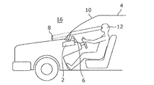
まず、図1〜図3を参照しながら、実施の形態1に係るヘッドアップディスプレイ2の概略構成について説明する。図1は、実施の形態1に係るヘッドアップディスプレイ2の使用例を示す図である。図2は、実施の形態1に係るヘッドアップディスプレイ2により表示される画像8の領域11を示す図である。図3は、実施の形態1に係るヘッドアップディスプレイ2により表示される画像8の一例を示す図である。
(Embodiment 1)
[1-1. General configuration of head-up display]
First, a schematic configuration of the head-up
図1に示すように、実施の形態1に係るヘッドアップディスプレイ2は、例えば車両用のヘッドアップディスプレイであり、自動車4(車両の一例)のダッシュボード6の内部に配置されている。
As shown in FIG. 1, the head-up
図1及び図2に示すように、このヘッドアップディスプレイ2では、虚像である画像8を表示するためのレーザ光(光の一例)を例えば自動車4のウインドシールド10の運転席寄り下側の領域11に向けて投射することにより、レーザ光をウインドシールド10で運転者12に向けて反射させる。これにより、図3に示すように、運転者12は、ウインドシールド10の前方の景色14上に、虚像である画像8を重ね合わせて見ることができる。すなわち、ヘッドアップディスプレイ2は、虚像である画像8をウインドシールド10の前方の空間16に表示(投影)する。
As shown in FIGS. 1 and 2, in the head-
図3に示す例では、ヘッドアップディスプレイ2により表示される画像8は、鉛直画像18と奥行き画像20とを含んでいる。鉛直画像18は、ウインドシールド10の前方の空間16において鉛直方向(図1において上下方向)に表示される虚像である。鉛直画像18は、例えば縦長の略楕円形状のマークであり、自動車4の前方に存在する歩行者22に重畳して表示される。これにより、運転者12は、歩行者22の存在に容易に気付くことができる。
In the example illustrated in FIG. 3, the
一方、奥行き画像20は、ウインドシールド10の前方の空間16において、鉛直方向と交差する方向である奥行き方向(図1において左右方向)に表示される虚像である。奥行き画像20は、例えば目的地までの走行経路を案内するための矢印(図3に示す例では、交差点を右折するように指示するための矢印)であり、自動車4の前方に存在する道路24に重畳して表示される。これにより、運転者12は、目的地までの走行経路を容易に知ることができる。
On the other hand, the
[1−2.ヘッドアップディスプレイの具体的構成]
次に、図4及び図5を参照しながら、実施の形態1に係るヘッドアップディスプレイ2の具体的構成について説明する。図4は、実施の形態1に係るヘッドアップディスプレイ2の構成を示す図である。図5は、実施の形態1に係るヘッドアップディスプレイ2の機能構成を示すブロック図である。
[1-2. Specific configuration of head-up display]
Next, a specific configuration of the head-up
図4及び図5に示すように、ヘッドアップディスプレイ2は、投射部26、可動スクリーン28、駆動部30、投影部32(光学系の一例)及び制御部34を備えている。
As shown in FIGS. 4 and 5, the head-up
投射部26は、光源36及び走査部38を有している。光源36は、赤色成分(R)のレーザ光を出射する赤色レーザダイオードと、緑色成分(G)のレーザ光を出射する緑色レーザダイオードと、青色成分(B)のレーザ光を出射する青色レーザダイオードとを有している。光源36から出射した赤色成分のレーザ光と緑色成分のレーザ光と青色成分のレーザ光とは、例えばダイクロイックミラー(図示せず)により合成された後に、走査部38に入射する。
The
走査部38は、例えばMEMS(Micro Electro Mechanical Systems)ミラーで構成されている。走査部38は、入射したレーザ光を自己の振れ角に応じた方向に反射することにより、光源36からのレーザ光を可動スクリーン28に向けて二次元的にラスタ走査する。走査部38は、例えば可動スクリーン28の両端の一端から他端に向かう方向にレーザ光をラスタ走査する。
The
可動スクリーン28は、透光性を有する(例えば半透明の)矩形状のスクリーンである。図5に示すように、可動スクリーン28は、走査部38からのレーザ光の光路上において、走査部38から離れる方向(図5中の矢印Xで示す方向(X方向))及び走査部38に近付く方向(図5中の矢印Yで示す方向(Y方向))に往復移動自在に配置されている。また、可動スクリーン28は、可動スクリーン28の移動方向(X方向及びY方向)に対して傾斜した姿勢で往復移動する。
The
可動スクリーン28がX方向に移動している状態で、走査部38からのレーザ光が可動スクリーン28に向けてラスタ走査されることにより、可動スクリーン28に画像が形成される。一方、可動スクリーン28がY方向に移動している状態で、走査部38からのレーザ光が可動スクリーン28に向けてラスタ走査されることにより、可動スクリーン28に別の画像が形成される。なお、可動スクリーン28の代わりに固定されたスクリーンを採用してもよい。
An image is formed on the
駆動部30は、例えばアクチュエータで構成されている。駆動部30は、制御部34からの駆動信号に基づいて、一定の周波数(例えば60Hz)且つ一定の振幅(例えば1mm)で可動スクリーン28をX方向及びY方向に往復移動(振動)させる。なお、駆動部30は、制御部34からの駆動信号に基づいて、可動スクリーン28がX方向(又はY方向)に移動する間の時間が例えば25msec以下になるように、可動スクリーン28を往復移動させる。
The
投影部32は、拡大レンズ44、第1の反射板46、第2の反射板48、フレネルレンズ50及びウインドシールド10を含んでいる。
The
拡大レンズ44は、可動スクリーン28を透過したレーザ光の光路上に配置されている。拡大レンズ44は、可動スクリーン28に形成された画像を拡大する。
The magnifying
第1の反射板46及び第2の反射板48は、拡大レンズ44からのレーザ光の光路上に配置され、拡大レンズ44からのレーザ光をウインドシールド10に向けて反射させる。これにより、第1の反射板46及び第2の反射板48は、拡大レンズ44により拡大された画像を、フレネルレンズ50を介してウインドシールド10に向けて投影する。
The first reflecting
フレネルレンズ50は、拡大レンズ44により拡大されて広がっている画像の広がり角度を狭めることで、ウインドシールド10上のアイボックス80に対応する範囲の大きさに調整して投影する。なお、アイボックス80とは、運転者12(観察者)の眼が存在すると想定された所定の範囲である。
The
ウインドシールド10は、フレネルレンズ50からのレーザ光の光路上に配置され、フレネルレンズ50からのレーザ光をアイボックス80に向けて反射させる。これにより、可動スクリーン28に所定の画像が形成されている場合には、所定の画像の虚像である鉛直画像18がウインドシールド10の前方の空間16に表示される。
The
制御部34は、駆動部30に駆動信号を出力する機能と、光源36に供給される駆動電流を制御する機能と、走査部38の振れ角を制御する機能とを有している。制御部34は、例えばCPU(Central Processing Unit)又はプロセッサ等で構成されており、メモリ(図示せず)に記憶されたコンピュータプログラムを読み出してそれを実行することにより上記各機能を実行する。
The
[1−3.フレネルレンズの構成]
次に、図6及び図7を参照しながら、実施の形態1に係るフレネルレンズ50の具体的構成について説明する。図6は、実施の形態1に係るフレネルレンズを光軸の方向からみた場合の平面図である。図7は、図6のVII−VII断面図である。なお、図7の(a)は、フレネルレンズ50の断面図の全体を示す図であり、図7の(b)は、フレネルレンズ50の断面図の一部を拡大した図である。
[1-3. Configuration of Fresnel lens]
Next, a specific configuration of the
図6及び図7に示すように、フレネルレンズ50は、矩形板状の部材であり、光の入射側に配置される平面52と、光の出射側に配置される鋸歯状の凹凸面51とを有する。つまり、フレネルレンズ50の凹凸面51と反対側の面は、平面52である。なお、フレネルレンズ50は、例えば、アクリルなどの樹脂により構成されている。フレネルレンズ50の凹凸面51は、光軸Aに対して傾斜している第1面51aと、光軸Aに略平行な第2面51bとが交互に配置されて形成されている。また、凹凸面51は、図6に示すように、同心円状に形成されている。
As shown in FIGS. 6 and 7, the
第1面51aは、フレネルレンズ50への入射光を所定の焦点に向けて集光する集光面である。つまり、第1面51aは、フレネルレンズ50への入射光を所定の焦点に向けて屈折させる。また、第1面51aは、同心円状に複数形成されており、複数の第1面51aのうち内側(光軸A側)に配置される第1面51aほど光軸Aへの傾斜角が大きくなる。
The
第2面51bは、所定の焦点に向けて集光させない壁面である。第2面51bは、凸レンズの厚みを薄くするために、集光面である第1面51aをオフセットさせるために形成された壁面である。
The
互いに隣接しており、かつ、出射側に突出している凸形状を形成している第1面51a及び第2面51bにおいて、当該第1面51aは、当該第2面51bよりも外側に配置されている面である。
In the
フレネルレンズ50は、第1面51aのうち第2面51bと隣接している一部の領域に、遮光マスク53を有する。遮光マスク53は、具体的には、インクジェット印刷などにより、遮光性を有する塗料が吹き付けられることにより形成される塗膜である。なお、遮光マスク53は、第1面51aのうち内側(光軸A側)の一部の領域と、外側の一部の領域とに形成されている。遮光マスク53は、光軸Aの方向からみた場合に同心円状に複数形成されている。
The
[1−4.効果]
実施の形態1に係るフレネルレンズ50によれば、入射光のうち、光軸Aに略平行な第2面51bに反射された入射光a1、a2は遮光マスク53に当たるため、入射光a1、a2がフレネルレンズ50から外部へ向けて出射されることを防ぐことができる。また、入射光のうち、第2面51bに反射されていない入射光a3は遮光マスク53に当たらないため、フレネルレンズ50から外部に向けて出射することができる。このため、第2面51bに反射されることが原因となる迷光の発生を効果的に低減できる。
[1-4. effect]
According to the
[1−5.実施の形態1の変形例1]
上記実施の形態1に係るフレネルレンズ50では、遮光マスク53は、凹凸面51側に設けられている構成であるが、この構成に限らずに、平面52側に設けられている構成としてもよい。
[1-5.
In the
図8を参照しながら、実施の形態1の変形例1に係るフレネルレンズ50Aの具体的な構成について説明する。図8は、実施の形態1の変形例1に係るフレネルレンズの図7に相当する断面図である。なお、実施の形態1の変形例1に係るフレネルレンズ50Aの遮光マスク53Aを除く構成は、実施の形態1に係るフレネルレンズ50の遮光マスク53を除く構成と同様の構成であるものとする。
A specific configuration of the
上述したように、フレネルレンズ50Aは、実施の形態1のフレネルレンズ50と比較して、遮光マスク53Aが形成される面が入射側の平面52であることが異なる。つまり、遮光マスク53Aは、平面52の、第2面51bに対向する位置に形成されている。例えば、遮光マスク53Aは、図8の(b)に示すように、平面52の領域のうちで、第2面51bで反射される角度でフレネルレンズ50Aに入射しようとしている入射光a4、a5がフレネルレンズ50Aに入射することを防ぐ領域に形成されている。一方で、遮光マスク53Aは、平面52のうちで、第2面51bで反射されない角度で入射しようとしている入射光a6がフレネルレンズ50Aに入射する領域には形成されていない。図8の(b)では、入射光a4、a5が遮光マスク53Aによって遮光されていない場合の光の経路を二点鎖線の矢印で示している。
As described above, the
なお、遮光マスク53Aが形成される領域は、入射光の角度と、当該入射光が平面52において屈折する角度と、フレネルレンズ50Aの形状とにより求めることができる。
The region where the
なお、遮光マスク53Aは、実施の形態1と同様に、光軸Aの方向からみた場合に同心円状に複数形成されている。 As in the first embodiment, a plurality of light shielding masks 53A are concentrically formed when viewed from the direction of the optical axis A.
[1−6.実施の形態1の変形例2]
上記実施の形態1及び変形例1に係るフレネルレンズ50、50Aでは、遮光マスク53は、フレネルレンズ50、50Aの表面に設けられている構成であるが、この構成に限らずに、フレネルレンズの光軸上に隣接して配置される透明な板状部材60に遮光マスク61を形成するフレネルレンズユニット70を採用した構成としてもよい。つまり、フレネルレンズ50、50Aの代わりに、遮光マスクが形成されていないフレネルレンズ50Bと遮光マスク61が形成されている板状部材60とを有するフレネルレンズユニット70を採用してもよい。
[1-6.
In the
図9を参照しながら、実施の形態1の変形例2に係るフレネルレンズユニット70の具体的な構成について説明する。図9は、実施の形態1の変形例2に係るフレネルレンズの図7に相当する断面図である。なお、フレネルレンズ50Bは、実施の形態1に係るフレネルレンズ50の遮光マスク53を除く構成と同様の構成であるものとする。
A specific configuration of the
図9に示すように、フレネルレンズユニット70は、遮光マスクが形成されていないフレネルレンズ50Bと、透明な板状部材60とを有する。
As shown in FIG. 9, the
板状部材60は、フレネルレンズ50Bに対向して配置される透明な板状部材(基板)であって、フレネルレンズ50Bの第2面51bに対向する位置に遮光マスク61が形成されている。例えば、遮光マスク61は、図9の(b)に示すように、板状部材60の入射側の面に形成されており、板状部材60の入射側の面のうちで、フレネルレンズ50Bの第2面51bによって反射された光a7、a8が当たる領域に形成されている。つまり、遮光マスク61は、フレネルレンズ50Bの第2面51bによって反射された光a7、a8が、フレネルレンズユニット70から出射することを防ぐ領域に形成されている。一方で、遮光マスク61は、板状部材60の入射側の面のうちで、第2面51bで反射されることなく出射された光a9が当たる領域には形成されていない。
The plate-
なお、遮光マスク61が形成される領域は、フレネルレンズ50Bに入射する光の角度と、当該光が平面52において屈折する角度と、当該光が第2面51bにおいて反射される角度と、当該光が凹凸面51において屈折する角度と、フレネルレンズ50Bの形状とにより求めることができる。
The region where the
[1−7.実施の形態1の変形例3]
上記実施の形態1に係るフレネルレンズ50では、特に言及していないが、遮光マスク53、図10に示すような形状を有していてもよい。
[1-7.
Although not particularly mentioned in the
図10は、実施の形態1の変形例3に係るフレネルレンズを光軸の方向からみた場合の平面図である。なお、図10の(a)は、フレネルレンズ50Cを光軸の方向からみた場合の平面図であり、図10の(b)は、図610(a)の一部を拡大した図である。
FIG. 10 is a plan view of a Fresnel lens according to the third modification of the first embodiment when viewed from the direction of the optical axis. 10A is a plan view when the
図10の(b)に示すように遮光マスク53Cのマスクパターンの端部は蛇行した形状を有する。具体的には、円状に形成された遮光マスク53Cのマスクパターンは、径方向の外側及び内側の端部が蛇行した形状となっている。
As shown in FIG. 10B, the end portion of the mask pattern of the
実施の形態1の遮光マスク53を用いたフレネルレンズ50では、入射光あるいは出射光が遮光マスク53で遮蔽されるため、遮光マスク53のマスクパターンのエッジ部分で光が回折してわずかな迷光を発生する。観察者からは、マスクパターンが淡く光って見えることになる。これに対して、実施の形態1の変形例3の遮光マスク53Cでは、端部の角度に応じて迷光が回折される方向を異なる方向とすることができ、回折光を広い角度に分散することができる。このため、観察者に視認される回折光を低減できる。
In the
なお、上述した遮光マスク53Cの形状は、実施の形態1の変形例1及び変形例2のフレネルレンズ50A及びフレネルレンズユニット70の遮光マスク53A、61に適用してもよい。
The shape of the
(実施の形態2)
次に実施の形態2に係るフレネルレンズ150について説明する。
(Embodiment 2)
Next, the
実施の形態2は、実施の形態1及びその変形例に係るフレネルレンズ50、50A及びフレネルレンズユニット70では、迷光の原因となる第2面51bでの反射光が出射されないように当該反射光を遮光する遮光マスク53、53A、61を形成している構成であるが、遮光マスク53、53A、61で迷光を遮光しない構成を採用している。
In the second embodiment, in the
[2−1.フレネルレンズの構成]
図11を参照しながら、実施の形態2に係るフレネルレンズ150の具体的な構成について説明する。図11は、実施の形態2に係るフレネルレンズの図7に相当する断面図である。
[2-1. Configuration of Fresnel lens]
A specific configuration of the
図11に示すように、実施の形態2に係るフレネルレンズ150は、光の入射側に平面152を有し、光の出射側に鋸歯状の凹凸面151を有する。つまり、フレネルレンズ150の凹凸面151と反対側の面は、平面152である。なお、フレネルレンズ150は、例えば、アクリルなどの樹脂により構成されている。フレネルレンズ150の凹凸面151は、同心円状に形成されている。
As shown in FIG. 11, the
第1面151aは、フレネルレンズ50への入射光を所定の焦点に向けて集光する集光面である。つまり、第1面151aは、フレネルレンズ150への入射光を所定の焦点に向けて屈折させる。また、第1面151aは、同心円状に複数形成されており、複数の第1面151aのうち内側(光軸A側)に配置される第1面151aほど光軸Aへの傾斜角が大きくなる。
The
第2面151bは、所定の焦点に向けて集光させない壁面である。第2面151bは、凸レンズの厚みを薄くするために、集光面である第1面151aをオフセットさせることで形成された壁面である。
The
出射側に突出している凸形状を形成している互いに隣接する第1面151a及び第2面151bにおいて、当該第1面151aは、当該第2面151bよりも外側に配置されている面である。
In the
第2面151bは、第2面151bに当たった光が、アイボックス80の範囲外に進む向きに反射する角度で、フレネルレンズ150の光軸Aに対して傾いて形成されている。第2面151bは、入射側から出射側に向かうほど外側に広がるように光軸Aに対して傾いて形成されている。つまり、第1面151a及び第2面151bは、光軸Aの方向からみた場合に、互いに重ならない領域に形成されている。
The
また、凹凸面151を形成している複数の第2面151bのうち、第1壁面よりも外側に配置される第2壁面は、第1壁面よりも光軸に対して傾いて形成されている。
Moreover, the 2nd wall surface arrange | positioned outside the 1st wall surface among the several
フレネルレンズ150は、具体的には、次のように、構成することができる。
Specifically, the
運転者12から虚像である画像8までの距離を2m、運転者12からフレネルレンズまでの距離を1m、画像8の水平方向の幅を400mm、アイボックス80の水平方向の幅を130mmとした場合を考える。この場合、フレネルレンズ150の水平方向の幅は270mm、フレネルレンズ150への入射角θinは、フレネルレンズ150の光軸A付近の部分で約±4度、フレネルレンズ150の水平方向の端部で4〜12度となる。このとき、フレネルレンズ150の第2面151bの傾斜角θsは、フレネルレンズ150の光軸A付近の部分で4度以上、フレネルレンズ150の水平方向の端部で12度以上とすることで、第2面151bでの反射光をアイボックス80の範囲外にそらすことができる。
When the distance from the
[2−2.効果]
実施の形態2に係るフレネルレンズ150によれば、入射光のうち、焦点に向けて集光させない壁面としての第2面151bに反射された入射光a11は、アイボックス80の範囲外に進む向き(出射角度θo1)で出射されるため、観察者としての運転者12に視認されることを防ぐことができる。また、入射光のうち、第2面151aに反射されていない入射光a12はアイボックス80の範囲内に進む向き(出射角度θo2)で出射されるため、運転者12に視認させることができる。このため、第2面151aに反射されることが原因となる迷光が運転者に視認されることを効果的に低減できる。
[2-2. effect]
According to the
[2−3.実施の形態2の変形例1]
上記実施の形態2に係るフレネルレンズ150では、第1面151a及び第2面151bは、光軸Aの方向からみた場合に、互いに重ならない領域に形成されている構成であるが、この構成に限らない。
[2-3.
In the
図12を参照しながら、実施の形態2の変形例1に係るフレネルレンズ150Aの具体的な構成について説明する。図12は、実施の形態2の変形例1に係るフレネルレンズの図7に相当する断面図である。
A specific configuration of the
図12に示すように、フレネルレンズ150Aは、実施の形態2のフレネルレンズ150と比較して、第1面151Aaと第2面151Abとが、光軸から見て重なって配置されている点が異なる。つまり、第2面151Abは、フレネルレンズ150Aへの入射光が壁面に直接当たらない角度でフレネルレンズ150Aの光軸Aに対して傾いて形成されている。
As shown in FIG. 12, in the
これにより、フレネルレンズ150Aへの入射光が第2面151Abに直接反射することを防ぐことができるため、第2面151Aaに反射されることが原因となる迷光が運転者に視認されることを効果的に低減できる。
This prevents incident light on the
(その他の実施の形態)
以上、一つ又は複数の態様に係るヘッドアップディスプレイについて、上記実施の形態に基づいて説明したが、本発明は、この実施の形態に限定されるものではない。本発明の趣旨を逸脱しない限り、当業者が思い付く各種変形を本実施の形態に施したものや、異なる実施の形態又は変形例における構成要素を組み合わせて構築される形態も、一つ又は複数の態様の範囲内に含まれてもよい。
(Other embodiments)
The head-up display according to one or more aspects has been described based on the above embodiment, but the present invention is not limited to this embodiment. Unless departing from the spirit of the present invention, one or a plurality of modifications may be made to the present embodiment which are conceived by those skilled in the art or a combination of components in different embodiments or modifications. It may be included within the scope of the embodiments.
なお、通常のヘッドアップディスプレイは、視野角が20度以下と比較的小さいため、フレネルレンズに入射する光の入射角分布も比較的小さく、壁面の傾斜角も20度以下と比較的小さく設定できるため、光ロスが少なく効果的に反射光による迷光を防ぐことができる。しかしながら、本発明は、この実施の形態に限定されるものではない。 Since a normal head-up display has a relatively small viewing angle of 20 degrees or less, the incident angle distribution of light incident on the Fresnel lens is relatively small, and the inclination angle of the wall surface can be set to a relatively small value of 20 degrees or less. Therefore, stray light due to reflected light can be effectively prevented with little optical loss. However, the present invention is not limited to this embodiment.
例えば、上記各実施の形態では、上記各実施の形態では、ヘッドアップディスプレイ2(2A)を自動車4に搭載する場合について説明したが、これに限定されず、例えば自動二輪車、航空機、電車又は船舶等に搭載されてもよい。
For example, in each of the above embodiments, the case where the head-up display 2 (2A) is mounted on the
また、ヘッドアップディスプレイ2(2A)を車両に搭載する場合について説明したが、これに限定されず、例えばウェアラブルデバイスとして構成される眼鏡等に搭載されてもよい。 Moreover, although the case where the head-up display 2 (2A) is mounted on a vehicle has been described, the present invention is not limited thereto, and may be mounted on, for example, glasses configured as a wearable device.
なお、上記実施の形態において、各構成要素は、専用のハードウェアで構成されるか、各構成要素に適したソフトウェアプログラムを実行することによって実現されてもよい。各構成要素は、CPU又はプロセッサ等のプログラム実行部が、ハードディスク又は半導体メモリ等の記録媒体に記録されたソフトウェアプログラムを読み出して実行することによって実現されてもよい。 In the above embodiment, each component may be configured by dedicated hardware or may be realized by executing a software program suitable for each component. Each component may be realized by a program execution unit such as a CPU or a processor reading and executing a software program recorded on a recording medium such as a hard disk or a semiconductor memory.
また、以下のような場合も本発明に含まれる。 The following cases are also included in the present invention.
(1)上記の各装置は、具体的には、マイクロプロセッサ、ROM、RAM、ハードディスクユニット、ディスプレイユニット、キーボード、マウスなどから構成されるコンピュータシステムで実現され得る。RAM又はハードディスクユニットには、コンピュータプログラムが記憶されている。マイクロプロセッサが、コンピュータプログラムにしたがって動作することにより、各装置は、その機能を達成する。ここでコンピュータプログラムは、所定の機能を達成するために、コンピュータに対する指令を示す命令コードが複数個組み合わされて構成されたものである。 (1) Specifically, each of the above-described devices can be realized by a computer system including a microprocessor, a ROM, a RAM, a hard disk unit, a display unit, a keyboard, a mouse, and the like. A computer program is stored in the RAM or the hard disk unit. Each device achieves its functions by the microprocessor operating according to the computer program. Here, the computer program is configured by combining a plurality of instruction codes indicating instructions for the computer in order to achieve a predetermined function.
(2)上記の各装置を構成する構成要素の一部又は全部は、1個のシステムLSI(Large Scale Integration:大規模集積回路)から構成されているとしてもよい。システムLSIは、複数の構成部を1個のチップ上に集積して製造された超多機能LSIであり、具体的には、マイクロプロセッサ、ROM、RAMなどを含んで構成されるコンピュータシステムである。ROMには、コンピュータプログラムが記憶されている。マイクロプロセッサが、ROMからRAMにコンピュータプログラムをロードし、ロードしたコンピュータプログラムにしたがって演算等の動作することにより、システムLSIは、その機能を達成する。 (2) A part or all of the constituent elements constituting each of the above-described devices may be constituted by one system LSI (Large Scale Integration). The system LSI is an ultra-multifunctional LSI manufactured by integrating a plurality of components on a single chip, and specifically, a computer system including a microprocessor, ROM, RAM, and the like. . A computer program is stored in the ROM. The system LSI achieves its functions by the microprocessor loading a computer program from the ROM to the RAM and performing operations such as operations in accordance with the loaded computer program.
(3)上記の各装置を構成する構成要素の一部又は全部は、各装置に脱着可能なICカード又は単体のモジュールから構成されてもよい。ICカード又はモジュールは、マイクロプロセッサ、ROM、RAMなどから構成されるコンピュータシステムである。ICカード又はモジュールには、上記の超多機能LSIが含まれてもよい。マイクロプロセッサが、コンピュータプログラムにしたがって動作することにより、ICカード又はモジュールは、その機能を達成する。このICカード又はこのモジュールは、耐タンパ性を有してもよい。 (3) A part or all of the constituent elements constituting each of the above apparatuses may be configured from an IC card that can be attached to and detached from each apparatus or a single module. The IC card or module is a computer system that includes a microprocessor, ROM, RAM, and the like. The IC card or the module may include the super multifunctional LSI described above. The IC card or the module achieves its function by the microprocessor operating according to the computer program. This IC card or this module may have tamper resistance.
(4)本発明は、上記に示す方法で実現されてもよい。また、これらの方法をコンピュータにより実現するコンピュータプログラムで実現してもよいし、コンピュータプログラムからなるデジタル信号で実現してもよい。 (4) The present invention may be realized by the method described above. Further, these methods may be realized by a computer program realized by a computer, or may be realized by a digital signal consisting of a computer program.
また、本発明は、コンピュータプログラム又はデジタル信号をコンピュータ読み取り可能な記録媒体、例えば、フレキシブルディスク、ハードディスク、CD−ROM、MO、DVD、DVD−ROM、DVD−RAM、BD(Blu−ray(登録商標) Disc)、半導体メモリなどに記録したもので実現してもよい。また、これらの記録媒体に記録されているデジタル信号で実現してもよい。 The present invention also relates to a computer-readable recording medium such as a flexible disk, hard disk, CD-ROM, MO, DVD, DVD-ROM, DVD-RAM, BD (Blu-ray (registered trademark)). ) Disc), or recorded in a semiconductor memory or the like. Moreover, you may implement | achieve with the digital signal currently recorded on these recording media.
また、本発明は、コンピュータプログラム又はデジタル信号を、電気通信回線、無線又は有線通信回線、インターネットを代表とするネットワーク、データ放送等を経由して伝送してもよい。 In the present invention, a computer program or a digital signal may be transmitted via an electric communication line, a wireless or wired communication line, a network represented by the Internet, data broadcasting, or the like.
また、本発明は、マイクロプロセッサとメモリを備えたコンピュータシステムであって、メモリは、コンピュータプログラムを記憶しており、マイクロプロセッサは、コンピュータプログラムにしたがって動作してもよい。 The present invention may also be a computer system including a microprocessor and a memory. The memory may store a computer program, and the microprocessor may operate according to the computer program.
また、プログラム又はデジタル信号を記録媒体に記録して移送することにより、又はプログラム又はデジタル信号をネットワーク等を経由して移送することにより、独立した他のコンピュータシステムにより実施するとしてもよい。 The program or digital signal may be recorded on a recording medium and transferred, or the program or digital signal may be transferred via a network or the like, and may be implemented by another independent computer system.
(5)上記実施の形態及び上記変形例をそれぞれ組み合わせるとしてもよい。 (5) The above embodiment and the above modifications may be combined.
本発明のフレネルレンズは、例えば車載用のヘッドアップディスプレイ等に用いることができる。 The Fresnel lens of the present invention can be used for, for example, an in-vehicle head-up display.
2 ヘッドアップディスプレイ
4 自動車
6 ダッシュボード
8 画像
10 ウインドシールド
11 領域
12 運転者
14 景色
16 空間
18 鉛直画像
20 奥行き画像
22 歩行者
24 道路
26 投射部
28 可動スクリーン
30 駆動部
32 投影部
34 制御部
36 光源
38 走査部
44 拡大レンズ
46 第1の反射板
48 第2の反射板
50、50A、50B、150、150A フレネルレンズ
51、151 凹凸面
51a、151a、151Aa 第1面
51b、151b、151Ab 第2面
52、152 平面
53、53A、61 遮光マスク
60 板状部材
70 フレネルレンズユニット
80 アイボックス
a1〜a6、a11、a12 入射光
a7〜a9 光
2 Head-up
Claims (3)
前記第1面のうち前記第2面と隣接している内側の一部の領域と外側の一部の領域とに遮光マスクが形成されている
前記遮光マスクは、当該遮光マスク上のマスクパターンの端部が蛇行している形状を有する
フレネルレンズ。 A Fresnel lens having a serrated irregular surface formed by alternately arranging a first surface inclined with respect to an optical axis and a second surface parallel to the optical axis,
A light-shielding mask is formed in a part of the inner surface adjacent to the second surface and a part of the outer surface of the first surface.
The light shielding mask is a Fresnel lens having a shape in which an end portion of a mask pattern on the light shielding mask meanders .
前記フレネルレンズに対向して配置される透明な板状部材であって、前記第2面に対向する位置に遮光マスクが形成されている板状部材と、を備え、
前記遮光マスクは、当該遮光マスク上のマスクパターンの端部が蛇行している形状を有する
フレネルレンズユニット。 A first surface which is inclined relative to the optical axis, and a Fresnel lens having a serrated uneven surface second surface and parallel to the optical axis is formed are alternately arranged,
A transparent plate-like member disposed to face the Fresnel lens, wherein a light-shielding mask is formed at a position facing the second surface, and
The light shielding mask has a shape in which an end portion of a mask pattern on the light shielding mask meanders. Fresnel lens unit.
前記光源からの光を走査する走査部と、
前記走査部からの光が透過することにより画像が形成されるスクリーンと、
前記スクリーンに形成された前記画像の虚像を空間に表示する光学系と、を備え、
前記光学系は、請求項1に記載のフレネルレンズ、または、請求項2に記載のフレネルレンズユニットを含む
ヘッドアップディスプレイ。 A light source that emits light;
A scanning unit that scans light from the light source;
A screen on which an image is formed by transmission of light from the scanning unit;
An optical system that displays a virtual image of the image formed on the screen in space,
Wherein the optical system, a Fresnel lens according to claim 1 or a head-up display including a Fresnel lens unit according to claim 2,.
Priority Applications (4)
| Application Number | Priority Date | Filing Date | Title |
|---|---|---|---|
| JP2016009299A JP6610887B2 (en) | 2016-01-20 | 2016-01-20 | Fresnel lens and head-up display |
| US16/068,956 US10670780B2 (en) | 2016-01-20 | 2017-01-10 | Fresnel lens, Fresnel lens unit, and head-up display |
| DE112017000438.1T DE112017000438B4 (en) | 2016-01-20 | 2017-01-10 | Fresnel lens, Fresnel lens assembly and head-up display |
| PCT/JP2017/000380 WO2017126353A1 (en) | 2016-01-20 | 2017-01-10 | Fresnel lens, fresnel lens unit, and head-up display |
Applications Claiming Priority (1)
| Application Number | Priority Date | Filing Date | Title |
|---|---|---|---|
| JP2016009299A JP6610887B2 (en) | 2016-01-20 | 2016-01-20 | Fresnel lens and head-up display |
Publications (3)
| Publication Number | Publication Date |
|---|---|
| JP2017129753A JP2017129753A (en) | 2017-07-27 |
| JP2017129753A5 JP2017129753A5 (en) | 2018-06-21 |
| JP6610887B2 true JP6610887B2 (en) | 2019-11-27 |
Family
ID=59361755
Family Applications (1)
| Application Number | Title | Priority Date | Filing Date |
|---|---|---|---|
| JP2016009299A Active JP6610887B2 (en) | 2016-01-20 | 2016-01-20 | Fresnel lens and head-up display |
Country Status (4)
| Country | Link |
|---|---|
| US (1) | US10670780B2 (en) |
| JP (1) | JP6610887B2 (en) |
| DE (1) | DE112017000438B4 (en) |
| WO (1) | WO2017126353A1 (en) |
Families Citing this family (6)
| Publication number | Priority date | Publication date | Assignee | Title |
|---|---|---|---|---|
| GB2569208B (en) * | 2018-07-19 | 2019-12-04 | Envisics Ltd | A head-up display |
| JP7128448B2 (en) * | 2019-03-19 | 2022-08-31 | コニカミノルタ株式会社 | head-up display device |
| WO2020246509A1 (en) * | 2019-06-07 | 2020-12-10 | 株式会社ソニー・インタラクティブエンタテインメント | Fresnel lens and image observation device |
| CN112622767A (en) | 2019-10-08 | 2021-04-09 | 松下知识产权经营株式会社 | Display system and electronic rearview mirror system provided with same |
| CN115769020A (en) * | 2020-07-01 | 2023-03-07 | 美蓓亚三美株式会社 | Planar lighting device |
| CN114280708A (en) * | 2022-01-12 | 2022-04-05 | 京东方科技集团股份有限公司 | Fresnel lens, optical module and virtual reality device |
Family Cites Families (13)
| Publication number | Priority date | Publication date | Assignee | Title |
|---|---|---|---|---|
| JPS52143847A (en) * | 1976-05-26 | 1977-11-30 | Mitsubishi Electric Corp | Optical lens |
| JPH06123801A (en) * | 1992-10-14 | 1994-05-06 | Fujitsu Ltd | Light-transmissive plate and device using the same |
| JP3330786B2 (en) | 1994-09-13 | 2002-09-30 | シャープ株式会社 | Method of manufacturing Fresnel lens and projection image display device using the same |
| JP2970487B2 (en) * | 1995-07-25 | 1999-11-02 | 日産自動車株式会社 | Fresnel lens |
| JP2004286996A (en) | 2003-03-20 | 2004-10-14 | Dainippon Printing Co Ltd | Transmission type screen |
| JP2006323114A (en) * | 2005-05-19 | 2006-11-30 | Dainippon Printing Co Ltd | Manufacturing method for fresnel lens sheet, and fresnel lens sheet |
| JP2010262161A (en) | 2009-05-08 | 2010-11-18 | Toshiba Corp | Display, display method and vehicle |
| WO2011086654A1 (en) | 2010-01-13 | 2011-07-21 | パナソニック株式会社 | Diffraction grating lens, method for manufacturing same, and imaging device using same |
| JP2014043205A (en) | 2012-08-28 | 2014-03-13 | Dainippon Printing Co Ltd | Image display system for vehicle |
| US9335447B2 (en) * | 2013-11-21 | 2016-05-10 | Stryker Corporation | Fresnel lens with light-scattering preventive feature |
| JP6314584B2 (en) * | 2014-03-26 | 2018-04-25 | アイシン・エィ・ダブリュ株式会社 | Head-up display device |
| JP2016001209A (en) | 2014-06-11 | 2016-01-07 | 富士フイルム株式会社 | Eyepiece and imaging apparatus |
| JP2016176981A (en) * | 2015-03-18 | 2016-10-06 | 株式会社東芝 | Fresnel lens and manufacturing method thereof |
-
2016
- 2016-01-20 JP JP2016009299A patent/JP6610887B2/en active Active
-
2017
- 2017-01-10 WO PCT/JP2017/000380 patent/WO2017126353A1/en active Application Filing
- 2017-01-10 DE DE112017000438.1T patent/DE112017000438B4/en active Active
- 2017-01-10 US US16/068,956 patent/US10670780B2/en active Active
Also Published As
| Publication number | Publication date |
|---|---|
| DE112017000438T5 (en) | 2018-10-11 |
| US20190011611A1 (en) | 2019-01-10 |
| US10670780B2 (en) | 2020-06-02 |
| DE112017000438B4 (en) | 2021-09-02 |
| WO2017126353A1 (en) | 2017-07-27 |
| JP2017129753A (en) | 2017-07-27 |
Similar Documents
| Publication | Publication Date | Title |
|---|---|---|
| JP6610887B2 (en) | Fresnel lens and head-up display | |
| US10642032B2 (en) | Head-up display | |
| JP6098375B2 (en) | Head-up display device | |
| JP7065383B2 (en) | Display systems, information presentation systems, display system control methods, programs, and moving objects | |
| JP6056680B2 (en) | Head-up display device | |
| JP6375825B2 (en) | Head-up display device | |
| JP6512449B2 (en) | Display device | |
| JP6489371B2 (en) | Display device | |
| JP6562356B2 (en) | Display device | |
| JP2018205621A (en) | Virtual image display device, intermediate image forming part, and image display light generation unit | |
| JP2017067944A (en) | Display image generation device and image display device | |
| JP2015022158A (en) | Optical scanner and image display device | |
| US10432899B2 (en) | Image display device | |
| JP2018040842A (en) | Head-up display device | |
| JP6710017B2 (en) | Image display | |
| JP6820502B2 (en) | Image display device | |
| JP6726883B2 (en) | Display system, moving body, and control method for display system | |
| US11768370B2 (en) | Projector, display system, and mobile object | |
| JP7367525B2 (en) | Display devices, display systems and mobile objects | |
| WO2018030203A1 (en) | Display device | |
| JP7400605B2 (en) | heads up display | |
| US10502953B2 (en) | Display device, and mobile body having same | |
| JP2017207632A (en) | Projection type display device and head-up display | |
| JPWO2017199441A1 (en) | Projection optical system, head-up display device, and automobile | |
| JP2019179065A (en) | Headup display device |
Legal Events
| Date | Code | Title | Description |
|---|---|---|---|
| A521 | Request for written amendment filed |
Free format text: JAPANESE INTERMEDIATE CODE: A523 Effective date: 20180508 |
|
| A621 | Written request for application examination |
Free format text: JAPANESE INTERMEDIATE CODE: A621 Effective date: 20180508 |
|
| A131 | Notification of reasons for refusal |
Free format text: JAPANESE INTERMEDIATE CODE: A131 Effective date: 20190702 |
|
| A521 | Request for written amendment filed |
Free format text: JAPANESE INTERMEDIATE CODE: A523 Effective date: 20190830 |
|
| TRDD | Decision of grant or rejection written | ||
| A01 | Written decision to grant a patent or to grant a registration (utility model) |
Free format text: JAPANESE INTERMEDIATE CODE: A01 Effective date: 20190917 |
|
| A61 | First payment of annual fees (during grant procedure) |
Free format text: JAPANESE INTERMEDIATE CODE: A61 Effective date: 20191015 |
|
| R151 | Written notification of patent or utility model registration |
Ref document number: 6610887 Country of ref document: JP Free format text: JAPANESE INTERMEDIATE CODE: R151 |
|
| S111 | Request for change of ownership or part of ownership |
Free format text: JAPANESE INTERMEDIATE CODE: R313113 |
|
| S531 | Written request for registration of change of domicile |
Free format text: JAPANESE INTERMEDIATE CODE: R313531 |
|
| SZ03 | Written request for cancellation of trust registration |
Free format text: JAPANESE INTERMEDIATE CODE: R313Z03 |