WO2017122810A1 - 画像処理装置、画像処理方法、画像処理プログラム及び記憶媒体 - Google Patents
画像処理装置、画像処理方法、画像処理プログラム及び記憶媒体 Download PDFInfo
- Publication number
- WO2017122810A1 WO2017122810A1 PCT/JP2017/001108 JP2017001108W WO2017122810A1 WO 2017122810 A1 WO2017122810 A1 WO 2017122810A1 JP 2017001108 W JP2017001108 W JP 2017001108W WO 2017122810 A1 WO2017122810 A1 WO 2017122810A1
- Authority
- WO
- WIPO (PCT)
- Prior art keywords
- image
- frame
- frame image
- cutout
- unit
- Prior art date
- Legal status (The legal status is an assumption and is not a legal conclusion. Google has not performed a legal analysis and makes no representation as to the accuracy of the status listed.)
- Ceased
Links
Images








Classifications
-
- H—ELECTRICITY
- H04—ELECTRIC COMMUNICATION TECHNIQUE
- H04N—PICTORIAL COMMUNICATION, e.g. TELEVISION
- H04N23/00—Cameras or camera modules comprising electronic image sensors; Control thereof
- H04N23/60—Control of cameras or camera modules
- H04N23/61—Control of cameras or camera modules based on recognised objects
-
- H—ELECTRICITY
- H04—ELECTRIC COMMUNICATION TECHNIQUE
- H04N—PICTORIAL COMMUNICATION, e.g. TELEVISION
- H04N23/00—Cameras or camera modules comprising electronic image sensors; Control thereof
- H04N23/60—Control of cameras or camera modules
- H04N23/68—Control of cameras or camera modules for stable pick-up of the scene, e.g. compensating for camera body vibrations
- H04N23/682—Vibration or motion blur correction
- H04N23/683—Vibration or motion blur correction performed by a processor, e.g. controlling the readout of an image memory
-
- H—ELECTRICITY
- H04—ELECTRIC COMMUNICATION TECHNIQUE
- H04N—PICTORIAL COMMUNICATION, e.g. TELEVISION
- H04N23/00—Cameras or camera modules comprising electronic image sensors; Control thereof
- H04N23/60—Control of cameras or camera modules
- H04N23/68—Control of cameras or camera modules for stable pick-up of the scene, e.g. compensating for camera body vibrations
- H04N23/681—Motion detection
- H04N23/6811—Motion detection based on the image signal
-
- H—ELECTRICITY
- H04—ELECTRIC COMMUNICATION TECHNIQUE
- H04N—PICTORIAL COMMUNICATION, e.g. TELEVISION
- H04N23/00—Cameras or camera modules comprising electronic image sensors; Control thereof
- H04N23/60—Control of cameras or camera modules
- H04N23/68—Control of cameras or camera modules for stable pick-up of the scene, e.g. compensating for camera body vibrations
- H04N23/682—Vibration or motion blur correction
- H04N23/684—Vibration or motion blur correction performed by controlling the image sensor readout, e.g. by controlling the integration time
- H04N23/6842—Vibration or motion blur correction performed by controlling the image sensor readout, e.g. by controlling the integration time by controlling the scanning position, e.g. windowing
-
- H—ELECTRICITY
- H04—ELECTRIC COMMUNICATION TECHNIQUE
- H04N—PICTORIAL COMMUNICATION, e.g. TELEVISION
- H04N23/00—Cameras or camera modules comprising electronic image sensors; Control thereof
- H04N23/95—Computational photography systems, e.g. light-field imaging systems
- H04N23/951—Computational photography systems, e.g. light-field imaging systems by using two or more images to influence resolution, frame rate or aspect ratio
-
- G—PHYSICS
- G06—COMPUTING OR CALCULATING; COUNTING
- G06T—IMAGE DATA PROCESSING OR GENERATION, IN GENERAL
- G06T2207/00—Indexing scheme for image analysis or image enhancement
- G06T2207/10—Image acquisition modality
- G06T2207/10016—Video; Image sequence
-
- G—PHYSICS
- G06—COMPUTING OR CALCULATING; COUNTING
- G06T—IMAGE DATA PROCESSING OR GENERATION, IN GENERAL
- G06T2207/00—Indexing scheme for image analysis or image enhancement
- G06T2207/20—Special algorithmic details
- G06T2207/20112—Image segmentation details
- G06T2207/20132—Image cropping
-
- G—PHYSICS
- G06—COMPUTING OR CALCULATING; COUNTING
- G06T—IMAGE DATA PROCESSING OR GENERATION, IN GENERAL
- G06T7/00—Image analysis
- G06T7/10—Segmentation; Edge detection
- G06T7/11—Region-based segmentation
-
- H—ELECTRICITY
- H04—ELECTRIC COMMUNICATION TECHNIQUE
- H04N—PICTORIAL COMMUNICATION, e.g. TELEVISION
- H04N23/00—Cameras or camera modules comprising electronic image sensors; Control thereof
- H04N23/60—Control of cameras or camera modules
- H04N23/68—Control of cameras or camera modules for stable pick-up of the scene, e.g. compensating for camera body vibrations
- H04N23/681—Motion detection
- H04N23/6812—Motion detection based on additional sensors, e.g. acceleration sensors
-
- H—ELECTRICITY
- H04—ELECTRIC COMMUNICATION TECHNIQUE
- H04N—PICTORIAL COMMUNICATION, e.g. TELEVISION
- H04N23/00—Cameras or camera modules comprising electronic image sensors; Control thereof
- H04N23/60—Control of cameras or camera modules
- H04N23/69—Control of means for changing angle of the field of view, e.g. optical zoom objectives or electronic zooming
Definitions
- the present disclosure relates to an image processing apparatus, an image processing method, an image processing program, and a storage medium.
- Patent Document 1 describes an image processing apparatus. This apparatus determines an appropriate cutout area to be cut out from the captured frame image in order to eliminate the influence of camera shake or the like during moving image shooting. This device detects motion data indicating the degree of deviation between a frame image and a reference frame image (for example, a previously input frame image), and moves or deforms the cutout region according to the detected motion data, The cutout area is corrected so as to be stationary with respect to the camera movement.
- the cutout region includes a region other than the frame region where the frame image and the reference frame image overlap, there is a region in which the pixel information is not included in the image after the camera shake correction. May exist.
- Patent Document 2 describes a device that restricts a cutout area to the frame area described above when the original cutout area includes an area other than the frame area described above. This apparatus forcibly moves the cutout area into the frame area when the cutout area protrudes from the frame area.
- Patent Document 2 works in a direction to limit the camera shake correction function, there is a possibility that a sufficient camera shake correction function cannot be exhibited.
- camera shake correction is realized by complementing image information of an area other than the frame area described above from another image.
- image information in an area other than the frame area described above is complemented using a plurality of frame images before and after the frame image.
- this method needs to process a plurality of frame images, the calculation cost is very high, and it cannot be used as software incorporated in a portable terminal or the like.
- One aspect of the present disclosure is an image processing apparatus that performs camera shake correction on a frame image captured by an imaging apparatus.
- This apparatus includes an acquisition unit, an image generation unit, and a cutout unit.
- the acquisition unit acquires a plurality of frame images.
- the image generation unit connects the first frame image and the second frame image, which is one of several frames before and after the first frame image, among the plurality of frame images acquired by the acquisition unit.
- a composite image larger than the size of the first frame image and the second frame image is generated.
- the cutout unit sets a cutout region in the composite image and outputs an image in the cutout region as an output frame image.
- a composite image is generated by connecting a first frame image and a second frame image.
- the image processing apparatus can reduce the calculation cost for generating a composite image, compared to a case where a plurality of frame images are used to supplement image information in a region other than the frame region.
- a cutout region is set in a composite image that is larger than the first frame image and the second frame image. This eliminates the need to limit the region where the cutout region can be set within the first frame region, and thus increases the chances of fully exhibiting the camera shake correction function.
- the cutout unit may set a cutout region in the first frame image.
- the image generation unit may generate a composite image when the cutout unit cannot set the cutout region in the first frame image.
- the image generation unit may not generate a composite image when the cutout unit can set the cutout region in the first frame image. Since this image generation device does not generate a composite image when it is not necessary to enlarge the region where the cutout region can be set, the calculation cost can be further reduced.
- the image generation unit may select a second frame image to be joined to the first frame image from a frame group consisting of several frames before and after the first frame image.
- the image generation device can select the second frame image from a plurality of candidates.
- the acquisition unit may acquire a frame image from a moving image or a hyperlapse moving image. In one embodiment, the acquisition unit may acquire a frame image from the imaging device.
- the cutout unit may set the position of the cutout region according to the movement of the imaging device. Thereby, the image processing apparatus can cancel the movement of the imaging apparatus.
- the image generation unit may limit the search range of the joint position between the first frame image and the second frame image. Thereby, the image processing apparatus can suppress the calculation cost.
- the image processing apparatus further includes a magnification acquisition unit that acquires at least one of a zoom-in magnification, a zoom-out magnification, and a subject display magnification of the first frame image with respect to the second frame image. May be.
- the image generation unit does not generate a composite image when the change amount per unit time of the magnification acquired by the magnification acquisition unit is equal to or greater than the threshold value.
- the image processing apparatus can avoid a decrease in response by not generating a composite image when the calculation cost of the composite image is expected to increase.
- the image processing apparatus may further include a recognition unit that recognizes the size of the subject of the first frame image or the second frame image.
- the image generation unit does not generate a composite image when the size of the subject recognized by the recognition unit is greater than or equal to the threshold value.
- the image processing apparatus can avoid the deterioration of the image quality by not generating the composite image when the composite image is expected to be an unnatural image.
- the method includes an acquisition step, an image generation step, and a cutout step.
- acquisition step a plurality of frame images are acquired.
- image generation step among the plurality of frame images acquired in the acquisition step, the first frame image and the second frame image that is one of several frames before and after the first frame image are connected.
- a composite image larger than the size of the first frame image and the second frame image is generated.
- cutout step a cutout area is set in the composite image, and an image in the cutout area is output as an output frame image.
- Another aspect of the present disclosure is an image processing program that performs camera shake correction of a frame image captured by an imaging apparatus.
- the program causes the computer to function as an acquisition unit, an image generation unit, and a cutout unit.
- the acquisition unit acquires a plurality of frame images.
- the image generation unit connects the first frame image and the second frame image, which is one of several frames before and after the first frame image, among the plurality of frame images acquired by the acquisition unit.
- a composite image larger than the size of the first frame image and the second frame image is generated.
- the cutout unit sets a cutout region in the composite image and outputs an image in the cutout region as an output frame image.
- Another aspect of the present disclosure is a storage medium that stores an image processing program that performs camera shake correction of a frame image captured by an imaging apparatus.
- the program causes the computer to function as an acquisition unit, an image generation unit, and a cutout unit.
- the acquisition unit acquires a plurality of frame images.
- the image generation unit connects the first frame image and the second frame image, which is one of several frames before and after the first frame image, among the plurality of frame images acquired by the acquisition unit.
- a composite image larger than the size of the first frame image and the second frame image is generated.
- the cutout unit sets a cutout region in the composite image and outputs an image in the cutout region as an output frame image.
- the same effects as those of the image processing apparatus according to one aspect can be obtained.
- Another aspect of the present disclosure is an image processing apparatus that performs camera shake correction on a frame image captured by an imaging apparatus.
- This apparatus includes an acquisition unit, an image generation unit, and a cutout unit.
- the acquisition unit acquires a plurality of frame images.
- the cutout unit sets a cutout region in the plurality of frame images acquired by the acquisition unit, and outputs an image in the cutout region as an output frame image.
- an acquisition part acquires a frame image from a moving image or a hyperlapse moving image.
- the cutout unit searches for camera work by limiting the search range of the tree structure, and other than the searched camera work in the motion data
- a cutout region is set in the frame image so that the components are canceled out.
- this device when searching using a tree structure, the number of child nodes belonging to each parent node and the number of nodes existing at the same depth are limited. Thereby, this apparatus can reduce the calculation cost.
- FIG. 1 It is a functional block diagram of a portable terminal provided with the image processing apparatus which concerns on 1st embodiment. It is a hardware block diagram of a portable terminal. It is a figure explaining the relationship between the position of a cutting-out area
- FIG. 1 is an example in which the cutout area K i protrudes from the input frame image f i in . As shown in FIG. 1, a cutout area K i is set in the input frame image f i in . Image cut-out area K i is the output frame image.
- the output frame image includes a missing area D i in which pixel information is not defined.
- I is a number indicating the order of input and the like, and is an integer.
- the present disclosure proposes a new method for electronic stabilizers.
- the technique of the present disclosure stitches, for example, two adjacent frame images. Figure 2, by sewing the two pieces of input frame image, an example in which complement the missing region D i of cut region K i. As shown in FIG.
- the input frame image f i in and the input frame image f i-1 in that has been input immediately before are stitched along the seam 200, whereby the input frame image f i in and the input frame image f A composite image (polygon) larger than i-1 in is generated.
- the angle of view is effectively spread, and the unnaturalness of the composite image is reduced in a realistic processing time. Then, by cutting out the output frame image from the composite image, it is possible to realize both the image quality and the stabilization of the video at a low calculation cost.
- the image processing apparatus is an apparatus that performs camera shake correction on a frame image captured by an imaging apparatus.
- the image processing apparatus is used for, for example, continuous shooting of a plurality of images and moving image shooting.
- the image processing apparatus can be mounted on a mobile terminal with limited resources such as a mobile phone, a smartphone, a digital camera, and a PDA (Personal Digital Assistant).
- a mobile terminal with limited resources such as a mobile phone, a smartphone, a digital camera, and a PDA (Personal Digital Assistant).
- PDA Personal Digital Assistant
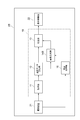
- FIG. 3 is a functional block diagram of the portable terminal 2 including the image processing apparatus 1 according to the present embodiment.
- the mobile terminal 2 shown in FIG. 3 is a mobile terminal carried by a user, for example, and has a hardware configuration shown in FIG.
- FIG. 4 is a hardware configuration diagram of the mobile terminal 2.
- the portable terminal 2 physically includes a main storage device such as a CPU (Central Processing Unit) 100, a ROM (Read Only Memory) 101, and a RAM (Random Access Memory) 102, a camera, or a keyboard. And the like, an output device 104 such as a display, and an auxiliary storage device 105 such as a hard disk.
- a main storage device such as a CPU (Central Processing Unit) 100, a ROM (Read Only Memory) 101, and a RAM (Random Access Memory) 102, a camera, or a keyboard.
- an output device 104 such as a display
- an auxiliary storage device 105 such as a hard disk.
- Each function of the portable terminal 2 and the image processing apparatus 1 to be described later is realized by reading predetermined computer software on hardware such as the CPU 100, the ROM 101, and the RAM 102. Specifically, each function of the portable terminal 2 and the image processing apparatus 1 described below operates the input device 103 and the output device 104 under the control of the CPU 100, and reads out data from the main storage device and the auxiliary storage device 105. And writing.
- the image processing apparatus 1 normally includes a main storage device such as the CPU 100, ROM 101, and RAM 102, an input device 103, an output device 104, an auxiliary storage device 105, and the like. It may be configured as a computer system.
- the mobile terminal 2 may include a communication module.
- the portable terminal 2 includes an imaging device 21, an image processing device 1, and a display control unit 22.
- the imaging device 21 is a device that captures continuous frame images in time series.
- An example of the imaging device 21 is a camera that captures a moving image.
- the moving image includes frame images that are continuous in time series.
- the imaging device 21 may have a continuous imaging function that repeatedly captures images at a predetermined interval from a timing designated by a user operation or the like.
- the imaging device 21 stores a frame image in a storage unit that can be referred to by the image processing device 1.
- the image processing device 1 generates an output frame image by inputting and processing the frame image obtained by the imaging device 21.
- the frame image includes pixel values.
- the pixel value is information associated with a pixel, and includes, for example, a luminance value, a color difference value, and saturation.
- the image processing apparatus 1 includes, for example, an acquisition unit 11, a motion data calculation unit 12, a cutout unit 13, and an image generation unit 14.
- the acquisition unit 11 acquires a plurality of frame images.
- the acquisition unit 11 is realized by the CPU 100 executing a program in the main storage device or the auxiliary storage device 105 and controlling the input device 103 according to the program. For example, the acquisition unit 11 acquires a plurality of frame images from the imaging device 21 as a plurality of input frame images.
- the motion data calculation unit 12 calculates a motion between frame images.
- the motion data calculation unit 12 is realized by the CPU 100 executing a program in the main storage device or the auxiliary storage device 105.
- the motion data calculation unit 12 associates coordinates between input frame images acquired by the acquisition unit 11.
- the motion data calculation unit 12 may calculate the difference between the input frame images and associate the coordinates between the frame images, or calculate the position change of the origin between the frame images to calculate the coordinates between the frame images. May be associated.
- the image processing apparatus 1 may include a gyro sensor, and the motion data calculation unit 12 may acquire a motion between the target frame image and the preceding and following frame images using a detection result by the gyro sensor. When the detection result by the gyro sensor is used, the robustness is excellent as compared with the case of using only the data of the frame image.
- the motion data calculation unit 12 When using a difference between frame images, the motion data calculation unit 12 adopts, for example, a pyramid image approach. In this case, first, the motion data calculation unit 12 performs block matching that minimizes the sum of absolute values of differences between frame images, and individually tracks feature points of Harris-Stephens that are sparsely selected. At this time, the motion data calculation unit 12 determines an initial vector for each block matching using the frame image converted to the lower layer. Then, the motion data calculation unit 12 calculates a perspective transformation between two adjacent frame images using the least square method. The coordinates between the two frame images are associated by the perspective transformation.
- the cutout unit 13 sets a cutout region in the first frame image or a composite image described later, and outputs an image in the cutout region as an output frame image.
- the cutout unit 13 is realized by the CPU 100 executing a program in the main storage device or the auxiliary storage device 105.
- the cutout unit 13 can set the position of the cutout region K i according to the movement of the imaging device 21.
- the cutout unit 13 sets the position of the cutout region K i according to the motion between the input frame images calculated by the motion data calculation unit 12, for example. Then, the cutout unit 13 outputs the image in the cutout region as an output frame image.
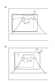
- Figure 5 is a diagram illustrating the relationship between the moving direction of the position and the imaging device 21 of the cut region K i. In the state of FIG. 5 (A), (B) , the input frame image sequentially captured by the imaging device 21 f i-1 in, and f i in, that the central position and Cf i-1, Cf i.
- the cutout unit 13 sets a cutout area K i-1 having a size smaller than that of the input frame image f i-1 in .
- the size of the cutout area K i-1 is 70 to 90% of the size of the input frame image f i-1 in .
- This cutout area K i-1 becomes an output frame image.
- the imaging device 21 has changed from the imaging position indicated by the state (A) to the imaging position indicated by the state (B) (shift to the upper right direction indicated by a solid line arrow in the state (B) in FIG. 5). In this case, the input frame image f i in shifted to the upper right than the input frame image f i-1 in is obtained.
- the cutout unit 13 sets the cutout region K i at a position where the movement between the input frame image f i-1 in and the input frame image f i in is canceled (state (B in FIG. 5)). ) In the lower left direction indicated by the dashed arrow). Accordingly, since the segment region K i-1 of the center position Cr i-1 and Cr i is the position of the same level, the output frame image as if stationary is generated though.
- FIG. 6 is a diagram for explaining the protrusion of the cutout area K i .
- the cut-out area K i set at a position that cancels the motion between the input frame images is the input frame. from the edge of the image f i in an outer region. Pixel information is not defined in the outer region than the edge of the input frame image f i in. Therefore, when the image cutting-out region K i was output frame image in this state, the output result unacceptable to the user.
- FIG. 7 is a diagram for explaining a complement cut region K i using two of the input frame image. As illustrated in FIG. 7, as an example, the pixel information of the entire cutout region K i is obtained by using the input frame image f i in to be processed and the immediately preceding input frame image f i ⁇ 1 in. can do.
- the cut area K i is generated by the input frame image f i in and the immediately preceding input frame image f i-1 in. If it is within the composite image, the function of camera shake correction can be sufficiently exerted. Further, even if the cutout area K i is outside the synthesized image, the amount to be pushed back into the area where the pixel information exists can be reduced compared to the case where only the input frame image f i in is used. Shake of the screen due to camera shake correction can be reduced. Note that the immediately following input frame image f i + 1 in may be used instead of the immediately preceding input frame image f i ⁇ 1 in .
- the image generation unit 14 connects the first frame image and the second frame image included in the plurality of frame images acquired by the acquisition unit 11 to generate a composite image.
- the image generation unit 14 is realized by the CPU 100 executing a program in the main storage device or the auxiliary storage device 105.
- the image generation unit 14 grasps the positional relationship between the frame images using the motion calculated by the motion data calculation unit 12, and connects the first frame image and the second frame image.
- the composite image includes part or all of the first frame image and part or all of the second frame image.
- the size of the composite image is larger than the sizes of the first frame image and the second frame image.
- the second frame image is one of several frames before and after the first frame image.
- the number of frames is, for example, about 1 to 5 frames.
- the image generation unit 14 may select a second frame image to be joined to the first frame image from a frame group including several frames before and after the first frame image.
- the image generation unit 14 may select a frame image that overlaps most with the cutout region from the frame group and set it as the second frame image.
- the image generation unit 14 may select a frame image that overlaps the cutout region by a predetermined region or more from the frame group, and may set the second frame image. For example, when the frame image immediately after the first frame image overlaps the cut-out area, the image generation unit 14 selects the frame image immediately after the first frame image as the second frame image.
- the image generation unit 14 determines a joint 200 of two input frame images, and combines the two input frame images along the joint 200 to generate a composite image.
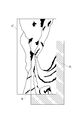
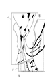
- FIG. 8 is a diagram for explaining a joint 200 between two input frame images.
- an intersection of four adjacent pixels P is set as a node N.
- the boundary between the two pixels P is defined as an edge E.
- the image generation unit 14 defines the cost of the edge by using the pixel value of the adjacent pixel across a certain edge. For example, the magnitude of the difference between the pixel values of adjacent pixels (for example, the difference in luminance value) is defined as the cost.
- the joint 200 is determined so that the sum of the costs of the edges on the route is minimized.
- the image generation unit 14 assigns a cost only to the edge E.
- the cost is defined using Equation (1) below.
- L A and L B are luminance values of arbitrary adjacent pixels (pixels A and B), and cost AB is the cost of the edge E between them.
- L main is a luminance value of a pixel of the first frame image f i in
- L sub is a luminance value of a pixel of the second frame image g i in .
- the image generation unit 14 uses the Dijkstra algorithm (CORMEN, TH, LEISERSON, CE, RIVEST, RL, AND STEIN, C. 2009. Introduction to algorithms.
- the image generation unit 14 can determine the seam 200 that is least noticeable.
- the image generation unit 14, as the seam 200 does not cross the missing region D i, may be set the cost of the neighborhood of the missing region D i to infinity.
- the image generation unit 14 may set the cost of the boundary portion of the output frame image to 0.
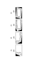
- FIG. 9 is a diagram for explaining types of missing areas.
- the types (A) to (D) in FIG. 9 are types of missing areas of the first frame image.
- Square outer frame is a first frame image, a region filled with black are missing region D i, hatched area expresses the missing region type.
- the missing region D i can be classified into four types.
- Type (A) is a missing region composed of rectangles attached to one side
- Type (B) is a missing region composed of two rectangles attached to two adjacent sides
- type (C) is a missing region composed of three rectangles attached to three sides
- type (D) is a missing region comprised of four rectangles attached to all sides. Since a general missing area is not composed of rectangles, when classifying, the missing areas are classified by combining 1 to 4 rectangles so as to reduce the area difference. The area approximated by the rectangle corresponds to the hatched area shown in FIG.
- the image generation unit 14 sets a search range, a search start position, and a search end position for each type of missing area.
- FIG. 10 is a diagram for explaining the search range, search start position, and search end position of the joint 200.
- a square outer frame is the first frame image.
- the search range is a range indicated by two types of hatching areas, and is set by extending the rectangular approximate area shown in FIG. 9, for example.
- the search range is set to be 2 to 4 times as wide as the width of the rectangular approximate region.
- the image generation unit 14 sets a search range, a search start position SP, and a search end position EP for each of the types (A) to (C). Thus, calculation cost is reduced by limiting the search range. Note that the type (D) in FIG. 9 cannot be handled by the Dijkstra algorithm. For this reason, a composite image is not generated for the type (D) in FIG.
- Cutting unit 13 the first frame image and the synthesized image is set to cut region K i relative path (coordinate space) to be drawn.
- the image generation unit 14 generates a composite image when the cutout unit 13 cannot set the cutout region K i in the first frame image, and the cutout unit 13 sets the cutout region K i in the first frame image. If it can be set to, a composite image is not generated. If the cutout area K i cannot be set in the composite image, the cutout unit 13 forcibly moves the cutout area K i into the composite image.
- the cutout section 13 The cutout area K i is forcibly moved into the image.
- the cutout unit 13 outputs an output frame image to the display control unit 22.
- the display control unit 22 is connected to a display device that can display an image or video, and displays an output frame image on the display device.
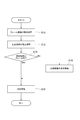
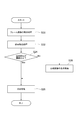
- FIG. 11 is a flowchart of output frame image generation processing of the image processing apparatus 1 according to the first embodiment. The generation process shown in FIG. 11 is executed, for example, at the timing when the imaging function of the mobile terminal 2 is turned on.
- the acquisition unit 11 of the image processing apparatus 1 acquires an input frame image as a first frame image as an acquisition process (S10: acquisition step).
- the acquisition unit 11 receives the first frame image from the imaging device 21, for example.
- the motion data calculation unit 12 of the image processing apparatus 1 calculates the motion with the second frame image that is one of several frames before and after the first frame image.
- cutting unit 13 of the image processing apparatus 1 includes, as setting processing (S12), sets the cut region K i.
- Cutting unit 13 so as to cancel the movement of the imaging device 21, the first frame image and the synthesized image is set to cut region K i relative path (coordinate space) to be drawn (see FIG. 5).
- Image generation unit 14 of the image processing apparatus 1 determines a determination process (S14), whether the segment region K i is the first frame image. When it is determined that the cut-out area K i is in the first frame image (S14: Yes), the cut-out unit 13 performs an image in the cut-out area K i as a cut-out process (S16: cut-out step). Is cut out as an output frame image. As a result, an output frame image is generated, and the generation process shown in FIG. 11 ends.
- the image generator 14 determines whether the cut region K i is determined to be not within the first frame image (S14: No). If the cut region K i is determined to be not within the first frame image (S14: No), the image generator 14 generates the processing: a (S18 image generating step), the first frame image and the second frame A composite image is generated by connecting the images. Alternatively, when a composite image cannot be generated (in the case of type (D) in FIG. 9), the image generation unit 14 outputs a signal indicating that to the clipping unit 13.
- cutting unit 13, as cutout process (S16) determines whether the cut region K i is the composite image. When it is determined that the cutout area K i is in the composite image, the cutout unit 13 cuts out the image in the cutout area K i as an output frame image. When it is determined that the cutout area K i is not in the composite image, the cutout unit 13 moves the cutout area K i into the composite image, and then cuts it out as an output frame image. Further, if the composite image by generating processing (S18) is not generated, cutting unit 13, as cutout process (S16), moving the cut region K i to the first frame image, then outputs the frame image Cut out as. As a result, the output frame image is generated, and the generation process shown in FIG. 11 is completed.
- the generation process illustrated in FIG. 11 ends.
- generating process shown in FIG. 11 is executed, even if the cut region K i was not protrude the first frame image, by joining the two frame images, cut region K i An output frame image can be generated without resetting. Further, even when resetting the cut region K i, by joining the two frame images, it is possible to reduce the amount of movement of the cut region K i. As a result, rattling due to camera shake correction can be suppressed. Furthermore, by combining two frame images, a stronger correction parameter can be adopted as compared with the case of one frame image.
- the image processing program includes a main module, an input module, and an arithmetic processing module.
- the main module is a part that comprehensively controls image processing.
- the input module operates the mobile terminal 2 so as to acquire a frame image.
- the arithmetic processing module includes a motion data calculation module, a cutout module, and an image generation module.
- the functions realized by executing the main module, the input module, and the arithmetic processing module are the functions of the acquisition unit 11, the motion data calculation unit 12, the cutout unit 13, and the image generation unit 14 of the image processing apparatus 1 described above, respectively. It is the same.
- the image processing program is stored in a storage medium such as a ROM or a semiconductor memory, for example.
- the image processing program may be provided via a network.
- the composite image is generated by connecting the first frame image and the second frame image.
- the image processing apparatus 1 can reduce the calculation cost for generating a composite image, compared to the case where a plurality of frame images are used to supplement image information in an area other than the frame area.
- the cutout area K i is set in a composite image that is larger than the first frame image and the second frame image. Accordingly, since there is no need to limit the settable region of the cut region K i in the first frame area, it increases opportunities that can sufficiently exhibit the camera shake correction function. As described above, the image processing apparatus 1 can exhibit the camera shake correction function while suppressing the calculation cost.
- the image processing apparatus 1 since does not generate a composite image where it is not necessary to expand the settable region of the cut region K i, can be further reduced computation cost. Moreover, since the image processing apparatus 1 sets the joint 200 so as to avoid a portion where the difference in luminance value is large, a natural result can be realized.
- the image processing apparatus 1A according to the second embodiment is different from the image processing apparatus 1 according to the first embodiment in the input source of the acquisition unit 11 and the operation of the cutout unit 13A, and the other is the same. .
- the description overlapping with the image processing apparatus 1 is omitted.
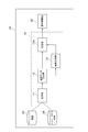
- FIG. 12 is a functional block diagram of the portable terminal 2A of the image processing apparatus 1A according to the second embodiment.
- the configuration of the image processing apparatus 1 ⁇ / b> A does not include the imaging device 21 compared to the image processing apparatus 1, and includes a moving image 23 and a hyperlapse moving image 24.
- the other configurations other than the cutout portion 13A are the same.
- the moving image 23 is data including frame images that are continuous in time series.
- the hyperlapse moving image 24 is data including frame images that are continuous in time series, and specifically, is a set of still images taken at regular intervals.
- the acquisition unit 11 acquires at least one of the moving image 23 and the hyperlapse moving image 24. That is, the second embodiment is not a real-time process but a case where stored data exists.
- Cutting unit 13A as compared with the cutting unit 13, setting processing of the segment region K i is different.
- the cutout unit 13 ⁇ / b> A cancels the motion data other than the camera work as a camera shake.
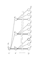
- the cutout unit 13A defines the cost of the camera work, and adopts the camera work that minimizes the cost as the final camera work.
- An ideal camera work is an operation that takes a cutting frame at the center of an image, and is basically an operation that maintains a constant-velocity linear motion.
- the cost is defined as the following formula (2) so that the cost becomes small when it is close to the ideal camera work.
- the first term on the right side is the product of the number N t of direction changes and the coefficient ⁇ t . That is, the cost is reduced in the case of camera work that continues linear motion at constant speed as much as possible and changes direction when it is unavoidable.
- the amount of deviation of the position of the cut region K i from the image center that is calculated for each frame image is the sum of. That is, in the case of camera work in which a clipping frame is brought to the center of the image, the cost is reduced.
- the third term on the right side is the product of the number N P (number of times of pressing) of moving the cutout area K i into the composite image or the first frame image and the coefficient ⁇ P. The smaller the number of push-in times, the more stable the camera shake correction.
- Equation (2) cannot be calculated because the assumed pattern is infinite.
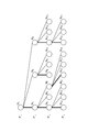
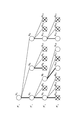
- the cutout unit 13A searches for an ideal camera work using the tree structure shown in FIGS. Specifically, the cutout unit 13A searches for camera work by limiting the search range of the tree structure. 13 to 16 are diagrams for explaining the search for camera work.
- each frame image is hierarchized.
- a circular node is displayed in each hierarchy.
- the node corresponds to the clipping process in each frame.
- Each node is associated with a cost defined by Equation (2).
- Equation (2) When the camera work continues a constant velocity linear motion from the current frame image (current node) to the next frame image (lower layer), an edge indicated by a bold line in the figure extends from the node.
- the camerawork turns around from the current frame image (current node) to the next frame image (lower layer)
- an edge indicated by a thin line in the figure extends from the node. That is, the route from the root to the leaf corresponds to a specific camera work.
- the calculation cost is reduced by limiting the number of direction turning patterns for each node to a finite number (two in the figure).
- the cutout unit 13A sets an upper limit value of the number of nodes for each frame image in order to further reduce the calculation cost. As a result, the nodes are selected in ascending order of cost until the upper limit is reached.
- the upper limit value of the number of nodes is set to “three”. That is, in the frame image f 2 in , the low-cost nodes N 5 , N 7 , and N 11 are adopted, and the remaining nodes N 6 , N 8 to N 10 , N 12 , and N 13 are not adopted. Similarly, in the frame image f 3 in , the low-cost nodes N 17 , N 18 , and N 19 are adopted, and the remaining nodes N 14 to N 16 , N 17 , N 20 , and N 21 are not adopted.
- the cutout unit 13A forcibly fixes the result of the frame image f 1 in at the time of the frame image f X in .
- the minimum cost at the time of the frame image f X in is the node N m + 3 .
- the result of the frame image f 1 in is fixed to the node N 3 that is an ancestor of the node N m + 3 .
- the node N 3 of the frame image f 1 in is set as a new route to configure a subtree.
- the cutout unit 13A needs to process information for the X frame image as an initial process at the start of processing, but can perform frame-by-frame processing by estimating the camera work as described above. In addition, it is possible to estimate a camera work that is close to the minimum in a realistic processing time.
- the same effect as the image processing apparatus 1 can be obtained even when the moving image 23 or the hyperlapse moving image 24 is used. Further, in this device, when searching using a tree structure, calculation is performed with the number of child nodes belonging to each parent node and the number of nodes existing at the same depth being limited. Thereby, this apparatus can reduce the calculation cost.
- the image processing device 1B according to the third embodiment is different from the image processing device 1 according to the first embodiment in that the magnification acquisition unit 15 is provided and the generation timing of the composite image of the image generation unit 14B is different. Others are the same. In the description of the image processing apparatus 1B, the description overlapping with the image processing apparatus 1 is omitted.
- FIG. 17 is a functional block diagram of the portable terminal 2B of the image processing apparatus 1B according to the third embodiment. As shown in FIG. 17, the configuration of the image processing apparatus 1 ⁇ / b> B is different from the image processing apparatus 1 in that it includes a magnification acquisition unit 15. The rest of the configuration other than the image generation unit 14B is the same.
- the magnification acquisition unit 15 acquires at least one of a zoom-in magnification, a zoom-out magnification, and a subject display magnification of the first frame image with respect to the second frame image.
- the magnification acquisition unit 15 is realized by the CPU 100 executing a program in the main storage device or the auxiliary storage device 105 and controlling the input device 103 according to the program.
- the magnification acquisition unit 15 acquires information on the magnification described above from the imaging device 21, for example.
- the magnification acquisition unit 15 may calculate information regarding the magnification by comparing the first frame image and the second frame image.
- the image generation unit 14B does not generate a composite image when the change amount per unit time of the magnification acquired by the magnification acquisition unit 15 is equal to or greater than a threshold value. This is because when the amount of change per unit time of the magnification acquired by the magnification acquisition unit 15 is greater than or equal to the threshold value, there is a high possibility of becoming the type (D) in FIG.
- the threshold value is a value set in advance to determine the amount of change.
- FIG. 18 is a flowchart of output frame image generation processing of the image processing apparatus 1B according to the third embodiment. The generation process illustrated in FIG. 18 is executed, for example, at the timing when the imaging function of the mobile terminal 2B is turned on.
- the acquisition unit 11 of the image processing apparatus 1B acquires an input frame image as a first frame image as an acquisition process (S20). This process is the same as the acquisition process (S10) of FIG.
- magnification acquisition unit 15 of the image processing apparatus 1B performs zoom-in magnification, zoom-out magnification, and subject display from the imaging device 21 to the second frame image of the first frame image as magnification acquisition processing (S22). Acquire at least one of the magnifications.
- the image generation unit 14B of the image processing apparatus 1B determines whether or not the change in magnification is greater than or equal to a threshold value as determination processing (S24). If the magnification change is determined to be equal to or greater than the threshold value (S24: Yes), cutting unit 13, as cutout process (S26), determines whether cut region K i is the first frame image To do. When it is determined that the cutout area K i is in the first frame image, the cutout unit 13 cuts out the image in the cutout area K i as an output frame image. When it is determined that the cutout area K i is not in the first frame image, the cutout unit 13 moves the cutout area K i into the first frame image, and then cuts it out as an output frame image. As a result, an output frame image is generated, and the generation process shown in FIG. 18 ends.
- the image generation unit 14B when it is determined that the change in magnification is not greater than or equal to the threshold (S24: No), the image generation unit 14B generates a composite image by connecting the first frame image and the second frame image as generation processing (S28). To do.
- cutting unit 13 determines whether the cut region K i is the composite image. When it is determined that the cutout area K i is in the composite image, the cutout unit 13 cuts out the image in the cutout area K i as an output frame image. When it is determined that the cutout area K i is not in the composite image, the cutout unit 13 moves the cutout area K i into the composite image, and then cuts it out as an output frame image. As described above, the output frame image is generated, and the generation process shown in FIG. 18 ends.
- the image processing apparatus 1C according to the fourth embodiment is different from the image processing apparatus 1 according to the first embodiment in that it includes a recognition unit 16 and the generation timing of the composite image of the image generation unit 14C. Are the same. In the description of the image processing apparatus 1C, the description overlapping with the image processing apparatus 1 is omitted.
- FIG. 19 is a functional block diagram of the portable terminal 2C of the image processing apparatus 1C according to the fourth embodiment. As shown in FIG. 19, the configuration of the image processing device 1 ⁇ / b> C is different from the image processing device 1 in that it includes a recognition unit 16. The rest of the configuration other than the image generation unit 14C is the same.
- the recognition unit 16 recognizes the size of the subject of the first frame image or the second frame image.
- the recognition unit 16 is realized by the CPU 100 executing a program in the main storage device or the auxiliary storage device 105.
- the recognition unit 16 recognizes the size of the subject using a well-known image processing technique.
- a subject is an object to be imaged.
- the image generation unit 14C does not generate a composite image when the size of the subject acquired by the recognition unit 16 is greater than or equal to the threshold value. This is because when the size of the subject is equal to or larger than the threshold, the image quality after the synthesis may be deteriorated.
- the threshold value is a value set in advance to determine the size of the subject.
- FIG. 20 is a flowchart of output frame image generation processing of the image processing apparatus 1C according to the fourth embodiment.
- the generation process illustrated in FIG. 20 is executed, for example, at the timing when the imaging function of the mobile terminal 2C is turned on.
- the acquisition unit 11 of the image processing apparatus 1C acquires an input frame image as a first frame image as an acquisition process (S30). This process is the same as the acquisition process (S10) of FIG.
- the recognition unit 16 of the image processing apparatus 1C recognizes the size of the subject of the first frame image, for example, as the recognition process (S32).
- the image generation unit 14C of the image processing apparatus 1C determines whether or not the size of the subject is equal to or greater than a threshold value as determination processing (S34). If the size of the subject is determined to be equal to or greater than the threshold value (S34: Yes), cutting unit 13, as cutout process (S36), whether or not cut region K i is the first frame image Determine. When it is determined that the cutout area K i is in the first frame image, the cutout unit 13 cuts out the image in the cutout area K i as an output frame image. When it is determined that the cutout area K i is not in the first frame image, the cutout unit 13 moves the cutout area K i into the first frame image, and then cuts it out as an output frame image. As a result, an output frame image is generated, and the generation process shown in FIG. 20 ends.
- the image generation unit 14C joins the first frame image and the second frame image as a generation process (S38), and forms a composite image. Is generated.
- cutting unit 13 determines whether the cut region K i is the composite image. When it is determined that the cutout area K i is in the composite image, the cutout unit 13 cuts out the image in the cutout area K i as an output frame image. When it is determined that the cutout area K i is not in the composite image, the cutout unit 13 moves the cutout area K i into the composite image, and then cuts it out as an output frame image. Thus, the output frame image is generated, and the generation process shown in FIG.
- the input source of the acquisition unit 11 may be the moving image 23 or the piper lapse moving image. That is, the image processing apparatus 1 is not limited to only real-time processing. Further, the image processing apparatus 1A only needs to be able to refer to the moving image 23 or the hyperlapse moving image 24, and may not include the storage unit itself for storing these. . Further, the image processing apparatuses 1 and 1A may capture and store a moving image, and then transmit the moving image to a server with high processing capability to cause the server to perform camera shake correction processing.
- the image processing apparatuses 1 and 1A do not generate a composite image when it is not necessary to enlarge the settable area of the cutout area K i , but change the processing so that a composite image is always generated. Also good.
- the image processing apparatuses 1 and 1A need not combine frame images having a time difference greater than a predetermined time threshold in consideration of the high probability of failure when frame images having a large time difference are combined. Good. Further, the image processing apparatuses 1 and 1A may change the time threshold using the number of moving subjects in the frame image to be photographed as an index. As a specific example, the image processing apparatuses 1 and 1A may reduce the time threshold if there are many moving subjects.
- the image processing apparatuses 1 and 1A may be configured to buffer the processing result and output the processing result with a slight delay for the reproduction of the recorded moving image or the hyperlapse moving image. Further, the image processing apparatuses 1 and 1A use the margin time at the time of frame image calculation processing or the estimated value of the margin time as a parameter, the search range of the joint or the number of frame images to be combined (for example, three or more), You may change for every frame image. The margin time may be increased as the amount of processing results buffered is increased.
- cutout unit 13A has been described as an example of cutting out from a composite image when performing a search using a tree structure, the target of cutout may not be a composite image.
- the image processing apparatus described in the embodiment may process as follows.
- the image processing apparatus may calculate only the outer frame of the composite image without generating the composite image itself. Further, the image processing apparatus may calculate only the vertex information when the outer frame is a polygon. Then, the image processing apparatus may determine the cutout frame using the outer frame information (or vertex information). Then, the image processing apparatus may perform joint search and synthesis at the same time as clipping. Thereby, compared with the case where all the images are synthesized, only the necessary part is processed, so that the calculation cost is reduced.
Landscapes
- Engineering & Computer Science (AREA)
- Multimedia (AREA)
- Signal Processing (AREA)
- Computing Systems (AREA)
- Theoretical Computer Science (AREA)
- Studio Devices (AREA)
- Image Processing (AREA)
Abstract
Description
撮像装置により撮像される映像又は画像を安定化させる電子式スタビライザが知られている。電子式スタビライザにおいては、手ブレをキャンセルするように入力フレーム画像を切り取ることによって、安定化された出力フレーム画像が得られる。しかしながら、切出領域が入力フレーム画像内に収まらない場合、出力フレーム画像は画素情報が定義されていない領域(欠落領域)を含むことになる。図1は、切出領域Kiが入力フレーム画像fi inからはみ出した例である。図1に示されるように、入力フレーム画像fi inに切出領域Kiが設定される。切出領域Ki内の画像が出力フレーム画像となる。切出領域Kiが入力フレーム画像fi inからはみ出した場合、出力フレーム画像は画素情報が定義されていない欠落領域Diを含む。なお、“i”は入力順などを示す番号であり、整数である。
本実施形態に係る画像処理装置は、撮像装置により撮像されたフレーム画像の手ブレ補正を行う装置である。画像処理装置は、例えば複数の画像の連続撮影や動画撮影に用いられる。画像処理装置は、例えば、携帯電話、スマートフォン、デジタルカメラ、PDA(Personal Digital Assistant)など、リソースに制限のあるモバイル端末に搭載され得る。しかしながら、画像処理装置は、これらの機器に搭載されることが必須ではなく、例えば通常のコンピュータシステムに搭載されてもよい。
図3は、本実施形態に係る画像処理装置1を備える携帯端末2の機能ブロック図である。図3に示される携帯端末2は、例えばユーザにより携帯される移動端末であり、図4に示すハードウェア構成を有する。図4は、携帯端末2のハードウェア構成図である。図4に示されるように、携帯端末2は、物理的には、CPU(Central Processing Unit)100、ROM(Read Only Memory)101及びRAM(Random Access Memory)102などの主記憶装置、カメラ又はキーボードなどの入力デバイス103、ディスプレイなどの出力デバイス104、ハードディスクなどの補助記憶装置105などを含む通常のコンピュータシステムとして構成される。後述する携帯端末2及び画像処理装置1の各機能は、CPU100、ROM101、RAM102などのハードウェア上に所定のコンピュータソフトウェアを読み込ませることにより、実現される。具体的には、後述する携帯端末2及び画像処理装置1の各機能は、CPU100の制御の元で入力デバイス103及び出力デバイス104を動作させるとともに、主記憶装置や補助記憶装置105におけるデータの読み出し及び書き込みを行うことで実現される。なお、上記の説明は携帯端末2のハードウェア構成として説明したが、画像処理装置1がCPU100、ROM101及びRAM102等の主記憶装置、入力デバイス103、出力デバイス104、補助記憶装置105などを含む通常のコンピュータシステムとして構成されてもよい。また、携帯端末2は、通信モジュールなどを備えてもよい。

図11は、第一実施形態に係る画像処理装置1の出力フレーム画像の生成処理のフローチャートである。図11に示される生成処理は、例えば携帯端末2の撮像機能をONしたタイミングで実行される。
以上、本実施形態に係る画像処理装置1、画像処理方法及び画像処理プログラムによれば、合成画像が第一フレーム画像と第二フレーム画像とを繋ぎ合わせることで生成される。このため、画像処理装置1は、複数枚のフレーム画像を用いてフレーム領域以外の領域の画像情報を補完する場合と比べて、合成画像を生成するための演算コストを抑えることができる。そして、第一フレーム画像及び第二フレーム画像よりも大きい合成画像に切出領域Kiが設定される。これにより、切出領域Kiの設定可能な領域を第一フレーム領域内に制限する必要が無くなるため、手ブレ補正機能を十分発揮することができる機会が増える。このように、画像処理装置1、演算コストを抑えつつ、手ブレ補正機能を発揮することができる。
第二実施形態に係る画像処理装置1Aは、第一実施形態に係る画像処理装置1と比べて、取得部11の入力元、及び、切出部13Aの動作が相違し、その他は同一である。画像処理装置1Aの説明において、画像処理装置1と重複する説明は省略される。
図12は、第二実施形態に係る画像処理装置1Aの携帯端末2Aの機能ブロック図である。図12に示されるように、画像処理装置1Aの構成は、画像処理装置1と比べて撮像装置21を備えておらず、動画23及びハイパーラプス動画24を備えている。そして、切出部13A以外のその他の構成は同一である。

以上、本実施形態に係る画像処理装置1A、画像処理方法及び画像処理プログラムによれば、動画23又はハイパーラプス動画24を用いた場合であっても、画像処理装置1と同一の効果を奏する。また、この装置においては、ツリー構造を用いて探索する際に、各親ノードに属する子ノードの数や、同じ深さに存在するノードの数などを制限した計算を行う。これにより、この装置は、演算コストを低減することができる。
第三実施形態に係る画像処理装置1Bは、第一実施形態に係る画像処理装置1と比べて、倍率取得部15を備える点、及び、画像生成部14Bの合成画像の生成タイミングが相違し、その他は同一である。画像処理装置1Bの説明において、画像処理装置1と重複する説明は省略される。
図17は、第三実施形態に係る画像処理装置1Bの携帯端末2Bの機能ブロック図である。図17に示されるように、画像処理装置1Bの構成は、画像処理装置1と比べて倍率取得部15を備える点が相違する。そして、画像生成部14B以外のその他の構成は同一である。
図18は、第三実施形態に係る画像処理装置1Bの出力フレーム画像の生成処理のフローチャートである。図18に示される生成処理は、例えば携帯端末2Bの撮像機能をONしたタイミングで実行される。
以上、本実施形態に係る画像処理装置1B、画像処理方法及び画像処理プログラムによれば、合成画像の演算コストが大きくなることが予想される場合には合成画像を生成しないことにより、レスポンスの低下を回避することができる。
第四実施形態に係る画像処理装置1Cは、第一実施形態に係る画像処理装置1と比べて、認識部16を備える点、及び、画像生成部14Cの合成画像の生成タイミングが相違し、その他は同一である。画像処理装置1Cの説明において、画像処理装置1と重複する説明は省略される。
図19は、第四実施形態に係る画像処理装置1Cの携帯端末2Cの機能ブロック図である。図19に示されるように、画像処理装置1Cの構成は、画像処理装置1と比べて認識部16を備える点が相違する。そして、画像生成部14C以外のその他の構成は同一である。
図20は、第四実施形態に係る画像処理装置1Cの出力フレーム画像の生成処理のフローチャートである。図20に示される生成処理は、例えば携帯端末2Cの撮像機能をONしたタイミングで実行される。
以上、本実施形態に係る画像処理装置1C、画像処理方法及び画像処理プログラムによれば、合成画像が不自然な画像となることが予想される場合には合成画像を生成しないことにより、画像品質の低下を回避することができる。
Claims (14)
- 撮像装置により撮像されたフレーム画像の手ブレ補正を行う画像処理装置であって、
複数の前記フレーム画像を取得する取得部と、
前記取得部により取得された複数のフレーム画像のうち、第一フレーム画像と、前記第一フレーム画像の前後数フレームの何れか一つのフレーム画像である第二フレーム画像とを繋ぎ合わせて前記第一フレーム画像及び前記第二フレーム画像の大きさよりも大きな合成画像を生成する画像生成部と、
前記合成画像に切出領域を設定し、前記切出領域内の画像を出力フレーム画像として出力する切出部と、
を備える画像処理装置。 - 前記切出部は、前記第一フレーム画像に前記切出領域を設定し、
前記画像生成部は、前記切出部により前記切出領域を前記第一フレーム画像内に設定できない場合には前記合成画像を生成し、前記切出部により前記切出領域を前記第一フレーム画像内に設定できる場合には前記合成画像を生成しない、請求項1に記載の画像処理装置。 - 前記画像生成部は、前記第一フレーム画像の前後数フレームからなるフレーム群から前記第一フレーム画像と繋ぎ合わせる前記第二フレーム画像を選択する請求項1又は2に記載の画像処理装置。
- 前記取得部は、動画から前記フレーム画像を取得する請求項1~3の何れか一項に記載の画像処理装置。
- 前記取得部は、ハイパーラプス動画から前記フレーム画像を取得する請求項1~3の何れか一項に記載の画像処理装置。
- 前記取得部は、前記撮像装置から前記フレーム画像を取得する請求項1~5の何れか一項に記載の画像処理装置。
- 前記切出部は、前記撮像装置の動きに応じて前記切出領域の位置を設定する請求項1~6の何れか一項に記載の画像処理装置。
- 前記画像生成部は、前記第一フレーム画像と前記第二フレーム画像との継目の位置の探索範囲を限定する請求項1~7の何れか一項に記載の画像処理装置。
- 前記第一フレーム画像の前記第二フレーム画像に対するズームインの倍率、ズームアウトの倍率、及び、被写体の表示倍率のうち少なくとも一つを取得する倍率取得部をさらに備え、
前記画像生成部は、前記倍率取得部により取得された倍率の単位時間当たりの変化量が閾値以上である場合には、前記合成画像を生成しない、請求項1~8の何れか一項に記載の画像処理装置。 - 前記第一フレーム画像又は前記第二フレーム画像の被写体の大きさを認識する認識部をさらに備え、
前記画像生成部は、前記認識部により認識された被写体の大きさが閾値以上である場合には、前記合成画像を生成しない、請求項1~9の何れか一項に記載の画像処理装置。 - 撮像装置により撮像されたフレーム画像の手ブレ補正を行う画像処理方法であって、
複数のフレーム画像を取得する取得ステップと、
前記取得ステップにより取得された複数のフレーム画像のうち、第一フレーム画像と前記第一フレーム画像の前後数フレームの何れか一つのフレーム画像である第二フレーム画像とを繋ぎ合わせて前記第一フレーム画像及び前記第二フレーム画像の大きさよりも大きな合成画像を生成する画像生成ステップと、
前記合成画像内に切出領域を設定し、前記切出領域内の画像を出力フレーム画像として出力する切出ステップと、
を備える画像処理方法。 - 撮像装置により撮像されたフレーム画像の手ブレ補正を行う画像処理プログラムであって、
コンピュータを、
複数の前記フレーム画像を取得する取得部、
前記取得部により取得された複数のフレーム画像のうち、第一フレーム画像と前記第一フレーム画像の前後数フレームの何れか一つのフレーム画像である第二フレーム画像とを繋ぎ合わせて前記第一フレーム画像及び前記第二フレーム画像の大きさよりも大きな合成画像を生成する画像生成部、及び、
前記合成画像内に切出領域を設定し、前記切出領域内の画像を出力フレーム画像として出力する切出部として機能させる、
画像処理プログラム。 - 撮像装置により撮像されたフレーム画像の手ブレ補正を行う画像処理プログラムを格納した記憶媒体であって、前記画像処理プログラムは、コンピュータを、
複数の前記フレーム画像を取得する取得部、
前記取得部により取得された複数のフレーム画像のうち、第一フレーム画像と前記第一フレーム画像の前後数フレームの何れか一つのフレーム画像である第二フレーム画像とを繋ぎ合わせて前記第一フレーム画像及び前記第二フレーム画像の大きさよりも大きな合成画像を生成する画像生成部、及び、
前記合成画像内に切出領域を設定し、前記切出領域内の画像を出力フレーム画像として出力する切出部として機能させる、
記憶媒体。 - 撮像装置により撮像されたフレーム画像の手ブレ補正を行う画像処理装置であって、
複数の前記フレーム画像を取得する取得部と、
前記取得部により取得された複数のフレーム画像に切出領域を設定し、前記切出領域内の画像を出力フレーム画像として出力する切出部と、
を備え、
前記取得部は、動画又はハイパーラプス動画から前記フレーム画像を取得し、
前記切出部は、フレーム画像ごとに階層化されたツリー構造を用いて探索する際に、前記ツリー構造の探索範囲を制限してカメラワークの探索を行い、動きデータのうち探索されたカメラワーク以外の成分が打ち消されるように、前記フレーム画像に切出領域を設定する、
画像処理装置。
Priority Applications (4)
| Application Number | Priority Date | Filing Date | Title |
|---|---|---|---|
| JP2017561202A JP6682559B2 (ja) | 2016-01-15 | 2017-01-13 | 画像処理装置、画像処理方法、画像処理プログラム及び記憶媒体 |
| KR1020187023322A KR102141290B1 (ko) | 2016-01-15 | 2017-01-13 | 화상 처리 장치, 화상 처리 방법, 화상 처리 프로그램 및 기억 매체 |
| CN201780006328.6A CN108463994B (zh) | 2016-01-15 | 2017-01-13 | 图像处理装置、图像处理方法和存储介质 |
| US16/068,701 US10931875B2 (en) | 2016-01-15 | 2017-01-13 | Image processing device, image processing method and storage medium |
Applications Claiming Priority (2)
| Application Number | Priority Date | Filing Date | Title |
|---|---|---|---|
| US201662279119P | 2016-01-15 | 2016-01-15 | |
| US62/279119 | 2016-01-15 |
Publications (1)
| Publication Number | Publication Date |
|---|---|
| WO2017122810A1 true WO2017122810A1 (ja) | 2017-07-20 |
Family
ID=59311786
Family Applications (1)
| Application Number | Title | Priority Date | Filing Date |
|---|---|---|---|
| PCT/JP2017/001108 Ceased WO2017122810A1 (ja) | 2016-01-15 | 2017-01-13 | 画像処理装置、画像処理方法、画像処理プログラム及び記憶媒体 |
Country Status (5)
| Country | Link |
|---|---|
| US (1) | US10931875B2 (ja) |
| JP (1) | JP6682559B2 (ja) |
| KR (1) | KR102141290B1 (ja) |
| CN (1) | CN108463994B (ja) |
| WO (1) | WO2017122810A1 (ja) |
Cited By (1)
| Publication number | Priority date | Publication date | Assignee | Title |
|---|---|---|---|---|
| CN109314744A (zh) * | 2017-12-29 | 2019-02-05 | 深圳市大疆创新科技有限公司 | 拍摄设备的图像处理方法、拍摄设备及可移动平台 |
Families Citing this family (10)
| Publication number | Priority date | Publication date | Assignee | Title |
|---|---|---|---|---|
| US10235587B2 (en) * | 2014-03-04 | 2019-03-19 | Samsung Electronics Co., Ltd. | Method and system for optimizing an image capturing boundary in a proposed image |
| CN110326027A (zh) * | 2017-01-24 | 2019-10-11 | 深圳市大疆创新科技有限公司 | 使用图像金字塔进行特征跟踪的方法和系统 |
| JP7405131B2 (ja) * | 2019-02-21 | 2023-12-26 | ソニーグループ株式会社 | 画像処理装置、画像処理方法、プログラム |
| US10983363B2 (en) * | 2019-09-19 | 2021-04-20 | Fotonation Limited | Method for stabilizing a camera frame of a video sequence |
| CN111698421B (zh) * | 2020-06-09 | 2021-12-17 | 展讯通信(上海)有限公司 | 一种图像处理方法、装置及计算机可读存储介质 |
| CN112738399B (zh) * | 2020-12-29 | 2022-10-25 | 维沃移动通信(杭州)有限公司 | 图像处理方法、装置和电子设备 |
| JP7468391B2 (ja) * | 2021-02-09 | 2024-04-16 | 株式会社Jvcケンウッド | 撮像装置および撮像処理方法 |
| US11748842B2 (en) | 2021-04-13 | 2023-09-05 | Qualcomm Incorporated | Methods and apparatus for content shifting in foveated rendering |
| US20250088744A1 (en) * | 2022-02-23 | 2025-03-13 | Gopro, Inc. | Dynamic image dimension adjustment |
| KR20240130490A (ko) * | 2023-02-22 | 2024-08-29 | 삼성전자주식회사 | 이미지 안정화 방법 및 이를 수행하는 전자 장치 |
Citations (2)
| Publication number | Priority date | Publication date | Assignee | Title |
|---|---|---|---|---|
| JP2004248249A (ja) * | 2003-01-21 | 2004-09-02 | Sony Corp | 撮像装置 |
| JP2007164570A (ja) * | 2005-12-15 | 2007-06-28 | Noritsu Koki Co Ltd | 撮影済み動画像の手振れ補正装置及び手振れ補正方法 |
Family Cites Families (12)
| Publication number | Priority date | Publication date | Assignee | Title |
|---|---|---|---|---|
| US7782362B2 (en) * | 2003-06-17 | 2010-08-24 | Panasonic Corporation | Image pickup device for changing a resolution of frames and generating a static image based on information indicating the frames |
| US20060120615A1 (en) * | 2004-12-06 | 2006-06-08 | Huiqiong Wang | Frame compensation for moving imaging devices |
| JP2007221710A (ja) | 2006-02-20 | 2007-08-30 | Seiko Epson Corp | 画像処理装置、撮影装置、画像処理方法、および、制御プログラム |
| JP4620607B2 (ja) | 2006-02-24 | 2011-01-26 | 株式会社モルフォ | 画像処理装置 |
| CN101489147B (zh) * | 2009-01-16 | 2010-12-01 | 西安电子科技大学 | 基于感兴趣区域的幅型比变换方法 |
| CN102714696B (zh) | 2010-11-11 | 2016-03-02 | 松下电器(美国)知识产权公司 | 图像处理装置、图像处理方法及摄影装置 |
| US9294676B2 (en) | 2012-03-06 | 2016-03-22 | Apple Inc. | Choosing optimal correction in video stabilization |
| JP2013228896A (ja) * | 2012-04-26 | 2013-11-07 | Sony Corp | 画像処理装置、画像処理方法、プログラム |
| KR101652658B1 (ko) | 2014-02-07 | 2016-08-30 | 가부시키가이샤 모르포 | 화상 처리 장치, 화상 처리 방법, 화상 처리 프로그램 및 기록 매체 |
| JP6250446B2 (ja) | 2014-03-19 | 2017-12-20 | 日本テレビ放送網株式会社 | 画像処理システム、画像処理装置、画像処理方法及びプログラム |
| US9392174B2 (en) * | 2014-12-11 | 2016-07-12 | Facebook, Inc. | Systems and methods for time-lapse selection subsequent to capturing media content |
| CN104994272A (zh) | 2015-06-12 | 2015-10-21 | 惠州Tcl移动通信有限公司 | 一种移动终端及其实现图像扫描的方法 |
-
2017
- 2017-01-13 CN CN201780006328.6A patent/CN108463994B/zh active Active
- 2017-01-13 WO PCT/JP2017/001108 patent/WO2017122810A1/ja not_active Ceased
- 2017-01-13 US US16/068,701 patent/US10931875B2/en active Active
- 2017-01-13 KR KR1020187023322A patent/KR102141290B1/ko active Active
- 2017-01-13 JP JP2017561202A patent/JP6682559B2/ja active Active
Patent Citations (2)
| Publication number | Priority date | Publication date | Assignee | Title |
|---|---|---|---|---|
| JP2004248249A (ja) * | 2003-01-21 | 2004-09-02 | Sony Corp | 撮像装置 |
| JP2007164570A (ja) * | 2005-12-15 | 2007-06-28 | Noritsu Koki Co Ltd | 撮影済み動画像の手振れ補正装置及び手振れ補正方法 |
Cited By (1)
| Publication number | Priority date | Publication date | Assignee | Title |
|---|---|---|---|---|
| CN109314744A (zh) * | 2017-12-29 | 2019-02-05 | 深圳市大疆创新科技有限公司 | 拍摄设备的图像处理方法、拍摄设备及可移动平台 |
Also Published As
| Publication number | Publication date |
|---|---|
| JPWO2017122810A1 (ja) | 2018-11-08 |
| CN108463994B (zh) | 2020-09-18 |
| JP6682559B2 (ja) | 2020-04-15 |
| CN108463994A (zh) | 2018-08-28 |
| US20190028645A1 (en) | 2019-01-24 |
| KR20180102639A (ko) | 2018-09-17 |
| US10931875B2 (en) | 2021-02-23 |
| KR102141290B1 (ko) | 2020-08-04 |
Similar Documents
| Publication | Publication Date | Title |
|---|---|---|
| JP6682559B2 (ja) | 画像処理装置、画像処理方法、画像処理プログラム及び記憶媒体 | |
| JP4941950B1 (ja) | 画像処理装置、画像処理方法及び画像処理プログラム | |
| US20090225174A1 (en) | Image processing apparatus, image processing method, hand shake blur area estimation device, hand shake blur area estimation method, and program | |
| JP2007226643A (ja) | 画像処理装置 | |
| JP2013058931A (ja) | 画像処理装置及び画像処理方法、並びにプログラム | |
| JP5978949B2 (ja) | 画像合成装置及び画像合成用コンピュータプログラム | |
| US9569823B2 (en) | Image processing device and method, and program for correcting a blurred moving image | |
| CN102017607A (zh) | 图像校正装置以及图像校正方法 | |
| WO2015119207A1 (ja) | 画像処理装置、画像処理方法、画像処理プログラム及び記録媒体 | |
| CN112734659A (zh) | 图像校正方法、装置及电子设备 | |
| US10095919B2 (en) | Image processing apparatus, image processing method and storage medium to suitably clip a subject region from a moving image | |
| US20120002842A1 (en) | Device and method for detecting movement of object | |
| JP2018061130A (ja) | 画像処理装置、画像処理方法、及びプログラム | |
| JP5493112B2 (ja) | 画像処理装置、画像処理方法及び画像処理プログラム | |
| JP5022498B2 (ja) | 画像処理装置、画像処理方法及び画像処理プログラム | |
| US7522189B2 (en) | Automatic stabilization control apparatus, automatic stabilization control method, and computer readable recording medium having automatic stabilization control program recorded thereon | |
| US20220375040A1 (en) | Image processing apparatus, image processing method, program, and electronic device | |
| JP2007006111A (ja) | トリミング制御装置及びトリミング制御プログラム | |
| JP5511403B2 (ja) | 画像処理装置およびその制御方法 | |
| CN110692235B (zh) | 图像处理装置、图像处理程序及图像处理方法 | |
| JP5979040B2 (ja) | 撮像装置、撮像方法及びプログラム | |
| JP2006285655A (ja) | 画像処理装置、画像処理方法及び画像処理プログラム | |
| US8913794B2 (en) | Image processing apparatus, image processing method, and medium | |
| JP4674549B2 (ja) | 動きベクトル検出装置 | |
| JP2012054787A (ja) | 画像処理装置及びその処理方法 |
Legal Events
| Date | Code | Title | Description |
|---|---|---|---|
| 121 | Ep: the epo has been informed by wipo that ep was designated in this application |
Ref document number: 17738562 Country of ref document: EP Kind code of ref document: A1 |
|
| ENP | Entry into the national phase |
Ref document number: 2017561202 Country of ref document: JP Kind code of ref document: A |
|
| NENP | Non-entry into the national phase |
Ref country code: DE |
|
| ENP | Entry into the national phase |
Ref document number: 20187023322 Country of ref document: KR Kind code of ref document: A |
|
| WWE | Wipo information: entry into national phase |
Ref document number: 1020187023322 Country of ref document: KR |
|
| 122 | Ep: pct application non-entry in european phase |
Ref document number: 17738562 Country of ref document: EP Kind code of ref document: A1 |